EP3745875B1 - Mikrokanalgefrierzylinderanordnung - Google Patents
Mikrokanalgefrierzylinderanordnung Download PDFInfo
- Publication number
- EP3745875B1 EP3745875B1 EP20741594.4A EP20741594A EP3745875B1 EP 3745875 B1 EP3745875 B1 EP 3745875B1 EP 20741594 A EP20741594 A EP 20741594A EP 3745875 B1 EP3745875 B1 EP 3745875B1
- Authority
- EP
- European Patent Office
- Prior art keywords
- cylinder
- header
- inlet
- orifices
- freezing
- Prior art date
- Legal status (The legal status is an assumption and is not a legal conclusion. Google has not performed a legal analysis and makes no representation as to the accuracy of the status listed.)
- Active
Links
Images


Classifications
-
- A—HUMAN NECESSITIES
- A23—FOODS OR FOODSTUFFS; TREATMENT THEREOF, NOT COVERED BY OTHER CLASSES
- A23G—COCOA; COCOA PRODUCTS, e.g. CHOCOLATE; SUBSTITUTES FOR COCOA OR COCOA PRODUCTS; CONFECTIONERY; CHEWING GUM; ICE-CREAM; PREPARATION THEREOF
- A23G9/00—Frozen sweets, e.g. ice confectionery, ice-cream; Mixtures therefor
- A23G9/04—Production of frozen sweets, e.g. ice-cream
- A23G9/045—Production of frozen sweets, e.g. ice-cream of slush-ice, e.g. semi-frozen beverage
-
- A—HUMAN NECESSITIES
- A23—FOODS OR FOODSTUFFS; TREATMENT THEREOF, NOT COVERED BY OTHER CLASSES
- A23G—COCOA; COCOA PRODUCTS, e.g. CHOCOLATE; SUBSTITUTES FOR COCOA OR COCOA PRODUCTS; CONFECTIONERY; CHEWING GUM; ICE-CREAM; PREPARATION THEREOF
- A23G9/00—Frozen sweets, e.g. ice confectionery, ice-cream; Mixtures therefor
- A23G9/04—Production of frozen sweets, e.g. ice-cream
- A23G9/22—Details, component parts or accessories of apparatus insofar as not peculiar to a single one of the preceding groups
- A23G9/222—Freezing drums
Definitions
- the present disclosure relates generally to freezing cylinder assemblies, and more particularly, to a microchannel freezing cylinder assembly used with a semi-frozen product dispensing apparatus.
- Microchannel heat exchangers are used as evaporators in order to freeze dairy product for soft serve and shake production.
- Current technology utilizes an external distributor and multiple inlets and outlets in order to distribute the refrigerant to the microchannel flow paths.
- WO2017214357 describe a cylindrical heat exchanger.
- WO2017176580 describes a frozen dispensing machine heat treatment system and method.
- EP1035387 describes an evaporator for a refrigeration system.
- This disclosure relates to a microchannel freezing cylinder assembly that relocates the distribution mechanism from external to the freezing cylinder to within the freezing cylinder through the use of a pressurized header, several orifices, a second distribution header, and an outlet header.
- Refrigerant may enter an inlet header through a single inlet.
- the refrigerant may flow around the inlet header and pass from the inlet header to a distribution header through several orifices, such as 4 to 16 orifices.
- the refrigerant may flow from the distribution header to the microchannels that extend along the cylinder.
- This header and orifice design will ensure that refrigerant is distributed equally around the cylinder.
- the refrigerant may exit the microchannels into an outlet header within the cylinder. There may be a single outlet connection on the cylinder.
- This disclosure moves the features which distribute and collect the refrigerant from outside the freezing cylinder to within the freezing cylinder.
- This design reduces the number of inlet connections on the freezing cylinder, such as from 10 to 1.
- the number of outlets on the freezing cylinder may be reduced from 8 to 1.
- the external distributor at the inlet and header at the outlet of the freezing cylinder will be eliminated with this design.
- This disclosure may reduce the cost to build the product through a reduction in the number of brazed joints and elimination of the external distributor and collector. This design may also improve the reliability through joint reduction.
- This disclosure includes a freezing cylinder for use in a semi-frozen product dispensing apparatus, the freezing cylinder with an inner cylinder having an inlet end and an outlet end; an outer cylinder having an inlet end and an outlet end, wherein the outer cylinder is disposed coaxially over the inner cylinder; a plurality of microchannels on an exterior surface of the inner cylinder that extend parallel with a longitudinal axis of the inner cylinder, wherein the plurality of microchannels are located between the inner cylinder and outer cylinder; a first inlet header around the circumference of the inner cylinder, wherein the first inlet header is located near the inlet end of the inner cylinder; a second inlet header around the circumference of the inner cylinder, wherein the second inlet header is located between the first inlet header and the plurality of microchannels, wherein the second inlet header is in fluid communication with the plurality of microchannels; a header ridge located between first inlet header and the second inlet header, wherein the header ridge is configured to prevent fluid to
- This disclosure includes a method of cooling a product with the freezing cylinder including the steps of providing a product to be cooled in an interior of the inner cylinder; adding refrigerant to the first inlet header through an inlet opening in the outer cylinder; moving refrigerant from the first inlet header to the second inlet header through the plurality of orifices; moving refrigerant from the second inlet header to the outlet header through the plurality of microchannels; and cooling the product by transferring heat from the product to the coolant as the refrigerant moves through the plurality of microchannels.
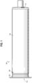
- a microchannel freezing cylinder assembly 100 used with a semi-frozen product dispensing apparatus is shown in Fig. 1 .
- the microchannel freezing cylinder assembly 100 includes a first cylinder 102 and a second cylinder 104.
- the second cylinder 104 may be disposed coaxially over the first cylinder 102.
- the second cylinder 104 may include a single inlet opening 106 and a single outlet opening 108 (shown in Fig. 2 ).
- the inlet opening 106 and outlet opening 108 may be located on generally opposite sides of the second cylinder 104.
- the inlet opening 106 is located at the twelve o'clock position and the outlet opening 108 is located at the six o'clock position when viewing the assembly 100 from an axial end.
- the inlet and outlet openings 106, 108 may be disposed to face in generally opposite directions, such as the inlet opening facing in a direction within a range of the ten o'clock position and the two o'clock position (inclusive of all positions within this range) while the outlet opening 108 may face in a direction with a range of the eight and four o'clock positions (inclusive of all positions within this range).
- the inlet and outlet openings 106, 108 may both face in the same direction, or the same "general direction" - which is defined herein to be plus or minus one hour on a clock face.
- the inlet opening 106 and outlet opening 108 may also be located on opposite ends of the second cylinder 104.
- First cylinder 102 may include an inner chamber configured to contain the semi-frozen product.
- the inner chamber may include a first inner chamber opening 110 and a second inner chamber opening 112.
- the refrigerant flowing in the microchannels may absorb heat from the semi-frozen product in the inner chamber and heat up and evaporate as it flows through the microchannels along the assembly 100. In this manner, the refrigerant and semi-frozen product may be in a heat exchange relationship such that the semi-frozen product is cooled.
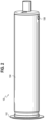
- Fig. 2 shows an assembly 100 that has been slightly rotated along the longitudinal axis from the view shown in Fig. 1 .
- Fig. 2 shows outlet opening 108 in second cylinder 104 that is located on the opposite side from inlet opening 106. Outlet opening 108 may be located on the bottom to allow gravity to assist removing the refrigerant from the assembly 100.
- First cylinder 102 may include an inlet header 114, a distribution header 116, and an outlet header 118.
- Inlet opening 106 is in fluid communication with the inlet header 114 when the first cylinder 102 is located within the second cylinder 104.
- Outlet opening 108 is in fluid communication with the outlet header 118 when the first cylinder 102 is located within the second cylinder 104.
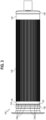
- First cylinder 102 may include several grooves 120 extending along the longitudinal length of first cylinder 102.
- the grooves 120 may form the microchannels (similar to element 121a ( Figs. 10 , 11 , 15 )) that contain the refrigerant.
- First cylinder 102 may include a ridge 122 located between the inlet header 114 and distribution header 116. Ridge 122 may include several orifices 124, for example 4 to 16 orifices 124.
- Orifices 124 may allow refrigerant to flow from inlet header 114 to distribution header 116.
- the refrigerant may flow around the circumference of inlet header 114 and pass from the inlet header 114 to the distribution header 116 through orifices 124.
- the pressure of the refrigerant in inlet header 114 may be higher than the pressure of the refrigerant in distribution header 116.
- Orifices 124 may collectively act as a restriction orifice in order to achieve a controlled or desired flow of the refrigerant from the inlet header 114 to the distribution header 116.
- Orifices 124 may restrict the flow of refrigerant from the inlet header 114 to the distribution header 116 by creating a permanent pressure loss between the inlet header 114 to the distribution header 116.
- the collective area of the orifices 124 determines the rate of refrigerant flow through the orifices 124.
- the refrigerant may flow around the circumference of the distribution header 116 to the microchannels that extend along the first cylinder 102.
- First cylinder 102 may include protrusions 126, 128 located at the ends of first cylinder 102. Protrusions 126, 128 may provide an interference fit with second cylinder 104 in order to contain the refrigerant between first cylinder 102 and second cylinder 104.
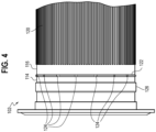
- Fig. 4 is a closer view of one end of first cylinder 102.
- Fig. 4 shows inlet header 114, distribution header 116, grooves 120, ridge 122, and orifices 124.
- Fig. 4 shows that the orifices 124 may be spaced circumferentially around ridge 122.
- the orifices 124 may be spaced evenly around ridge 122 or may be spaced unevenly around ridge 122 in order to optimize and/or even out the distribution of refrigerant into distribution header 116 and into the microchannels.
- Fig. 5 shows a detail view of a single orifice 124 with exemplary dimensions.
- Orifices 124 may be sized to collectively provide a desired cross-sectional area to allow refrigerant to flow from inlet header 114 to distribution header 116.
- Each orifice 124 may be generally rectangular in shape, as shown in Fig. 5 .
- the orifice(s) may be other shapes, such as triangular, curved (such as circular, semicircular or partially circular, or other geometrical or arbitrary shapes), as long as the remaining material forming the ridge 122 makes contact with the inner surface of the second cylinder 104 to prevent refrigerant from flowing across the ridge 122 other than through the orifices 124
- the depth and width of each orifice 124 may be varied as necessary to achieve the desired cross-sectional area, and one of ordinary skill with a thorough review of this disclosure will be able to design the number and size of orifices upon the ridge 122 without undue experimentation, as well as the other geometrical and numerical aspects of the inner cylinder.
- each orifice 124 may be approximately half the depth of ridge 122, or in other embodiments about 1/4, 1/3, or over half of the height of the ridge.
- the depth of each orifice 124 may be the depth of ridge 122 and each orifice 124 may be half, or 1/4, 1/3, or over half of the width of the orifice.
- each orifice 124 is a function of the number of orifices provided as well as the desired differential pressure across the ridge 122, and one of ordinary skill in the art would be able to design the desired orifices 124 to achieve the desired flow characteristics without undue experimentation.
- the depth and/or width of each orifice 124 may be selected for ease of manufacturability. For example, the width of each orifice 124, shown as 0.094 inches in Fig.
- each orifice 124 may be determined by the width of a tool, such as a drill bit, used to create each orifice 124 and the depth of each orifice 124 can be adjusted to achieve the desired cross-sectional area.
- a tool such as a drill bit
- the depth and width of the orifice may have a lower bounds based upon the diameter of the drill bits or other tools available to machine these features.
- Fig. 6 shows a detail view of grooves 120.
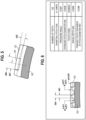
- Grooves 120 may have a gear-tooth profile, as shown in Fig. 6 , as opposed to a square profile. Exemplary dimensions for the gear-teeth are shown in the table in Fig. 6 .
- Using a gear-tooth profile instead of a square profile for grooves 120 may ease the manufacture of grooves 120.
- the grooves 120 may be manufactured with the use of a hobbing machine.
- Using a gear-tooth profile may also increase the strength of the microchannels by providing a wider base of the sides of grooves 120 at the exterior of first cylinder 102 than if a square profile were used.
- grooves with other profiles such as square, triangular, trapezoidal, or arcuate and the like may be used.
- grooves with other profiles such as square, triangular, trapezoidal, or arcuate and the like may be used.
- other grooves would be sufficient provided that they provided sufficient surface area for the needed heat transfer between the first cylinder 102 and the refrigerant and in conjunction allowed for a sufficient flow rate through the plurality of grooves based upon the supply pressure to the assembly 100, and provided that the outer edges of the grooves make sufficient contact with the inner surface of the second cylinder 104 to prevent refrigerant from flowing out of the grooves as it flows across the first cylinder.
- One of ordinary skill in the art would be able to establish a suitable geometry, size, and number of grooves with only routine optimization and without undue experimentation.
- first and second cylinders 102a, 104a may be reversed, with the second cylinder 104a still disposed coaxially over the first cylinder 102a and with coolant flowing across the outer surface of the first cylinder 102a between inlet and outlet openings 106a, 108a and with the semi-frozen product flowing through the chamber between the first and second openings 110a, 112a.
- components of similar functionality and structure are noted with consistent element numbers as the corresponding structure discussed above and depicted in FIGs. 1-6 with a letter modifying the element number.
- the structure and function of such components to the extent that it is the same as the embodiment above, will not be described in this embodiment, but any material differences in components is discussed herein).
- the outer surface of the first cylinder 102a may be a smooth cylindrical surface, with the inner surface of the second cylinder 104a comprising structures that form an inlet header 114a, protrusions 126a, 128a, ridge 122a (and orifices 124a) and grooves 120a that form microchannels 121a.
- the radial tips of these features contact and form an interference fit with the outer surface of the first cylinder 102a to establish the flow of refrigerant through the assembly 100a and to prevent flow from bypassing these features (opposite to the embodiments below where the radial tips of these features - as shown in FIGs. 1-6 - contact the inner surface of the second cylinder 104.
- the structure of first and second cylinders 102a, 104a and the components upon the inner surface of the second cylinder 104a are constructed in a like manner with the structure of the first and second cylinders 102, 104 discussed above.
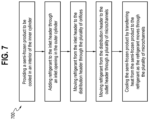
- Fig. 7 shows a method 700 of using the microchannel freezing cylinder assembly 100.
- Step 702 involves providing a semi-frozen product to be cooled in an interior of the inner cylinder.
- Step 704 adds refrigerant to the inlet header through an inlet opening in the outer cylinder.
- Step 706 moves refrigerant from the inlet header to the distribution header through the plurality of orifices.
- Step 708 moves refrigerant from the distribution header to the outlet header through the plurality of microchannels.
- Step 710 cools the semi-frozen product by transferring heat from the semi-frozen product to the refrigerant as the refrigerant moves through the plurality of microchannels.
Landscapes
- Life Sciences & Earth Sciences (AREA)
- Chemical & Material Sciences (AREA)
- Engineering & Computer Science (AREA)
- Food Science & Technology (AREA)
- Polymers & Plastics (AREA)
- Cooling Or The Like Of Semiconductors Or Solid State Devices (AREA)
Claims (15)
- Ein Gefrierzylinder (100) zur Verwendung in einer Ausgabevorrichtung für halbgefrorene Produkte, wobei der Gefrierzylinder (100) Folgendes umfasst:einen inneren Zylinder (102), der ein Eintrittsende und ein Austrittsende aufweist;einen äußeren Zylinder (104), der ein Eintrittsende und ein Austrittsende aufweist, wobei der äußere Zylinder (104) koaxial über dem inneren Zylinder (102) angeordnet ist;eine Vielzahl von Mikrokanälen (120) auf einer Außenfläche des inneren Zylinders (102), die sich parallel zu einer Längsachse des inneren Zylinders (102) erstreckt, wobei die Vielzahl von Mikrokanälen (120) zwischen dem inneren Zylinder (102) und äußeren Zylinder (104) liegen;einen ersten Eintrittskopf (114) um den Umfang des inneren Zylinders (102), wobei der erste Eintrittskopf (114) nahe dem Eintrittsende des inneren Zylinders (102) liegt;einen zweiten Eintrittskopf (116) um den Umfang des inneren Zylinders (102), wobei der zweite Eintrittskopf (116) zwischen dem ersten Eintrittskopf (114) und der Vielzahl von Mikrokanälen (120) liegt, wobei der zweite Eintrittskopf (116) in Fluidkommunikation mit der Vielzahl von Mikrokanälen (120) steht;eine zwischen dem ersten Eintrittskopf (114) und dem zweiten Eintrittskopf (116) liegende Kopfrippe (122), wobei die Kopfrippe (122) dafür konfiguriert ist, Fluidfluss von dem ersten Eintrittskopf (114) zu dem zweiten Eintrittskopf (116) zu verhindern;eine Vielzahl von Düsen (124) in der Kopfrippe (122), die dafür konfiguriert sind, Fluidfluss von dem ersten Eintrittskopf (114) zu dem zweiten Eintrittskopf (116) zu erlauben; undeinen Austrittskopf (118) um den Umfang des inneren Zylinders (102), wobei der Austrittskopf (118) nahe dem Austrittsende des inneren Zylinders (102) liegt, wobei der Austrittskopf (118) in Fluidkommunikation mit der Vielzahl von Mikrokanälen (120) steht.
- Der Gefrierzylinder nach Anspruch 1, der ferner eine in dem äußeren Zylinder (104) liegende Eintrittsöffnung (106) umfasst, die in Fluidkommunikation mit dem ersten Eintrittskopf (114) und einer in dem äußeren Zylinder (104) liegenden Austrittsöffnung (108) steht, die in Fluidkommunikation mit dem Austrittskopf (118) steht, wobei die Eintrittsöffnung (106) und Austrittsöffnung (108) auf entgegengesetzten Seiten einer Längsachse des äußeren Zylinders (104) liegen.
- Der Gefrierzylinder nach Anspruch 2, wobei die Eintrittsöffnung (106) in eine erste Richtung weist und die Austrittsöffnung (108) in eine generell entgegengesetzte Richtung von der ersten Richtung weist.
- Der Gefrierzylinder nach Anspruch 2, wobei die Eintrittsöffnung (106) und die Austrittsöffnung (108) jeweils in die gleiche generelle Richtung weisen.
- Der Gefrierzylinder nach Anspruch 3, wobei die Eintrittsöffnung (106) auf einer Oberseite des äußeren Zylinders (104) liegt und die Austrittsöffnung (108) auf einer Unterseite des äußeren Zylinders (104) liegt.
- Der Gefrierzylinder nach Anspruch 2, wobei keine der Vielzahl von Düsen (124) in einer Linie mit der Eintrittsöffnung (106) entlang einer Längsrichtung des inneren Zylinders (102) ist.
- Der Gefrierzylinder nach Anspruch 1, wobei die Vielzahl von Mikrokanälen (120) mit dem äußeren Zylinder (104) in Kontakt stehen.
- Der Gefrierzylinder nach Anspruch 1, wobei die Vielzahl von Mikrokanälen (120) jeweils ein Getriebezahnprofil aufweisen.
- Der Gefrierzylinder nach Anspruch 1, wobei jede der Vielzahl von Düsen (124) vier Seiten beinhaltet, wobei drei der Seiten durch die Kopfrippe (122) gebildet werden und eine Seite durch eine Innenfläche des äußeren Zylinders gebildet wird.
- Der Gefrierzylinder nach Anspruch 9, wobei eine Tiefe von jeder der Vielzahl von Düsen (124) ungefähr der halben Höhe der Kopfrippe (122) entspricht.
- Der Gefrierzylinder nach Anspruch 1, wobei jede der Vielzahl von Düsen (124) rechteckig geformt ist.
- Der Gefrierzylinder nach Anspruch 11, wobei eine Tiefe von jeder der Vielzahl von Düsen (124) ungefähr einem Drittel einer Breite von jeder der Vielzahl von Düsen (124) entspricht.
- Ein Verfahren zum Kühlen eines Produkts (700) mit dem Gefrierzylinder nach Anspruch 1, wobei das Verfahren Folgendes umfasst:Bereitstellen eines Produkts (702), das gekühlt werden soll, in einem Inneren des inneren Zylinders;Hinzufügen von Kältemittel (704) zu dem ersten Eintrittskopf über eine Eintrittsöffnung in dem äußeren Zylinder;Bewegen von Kältemittel (706) von dem ersten Eintrittskopf zu dem zweiten Eintrittskopf durch die Vielzahl von Düsen;Bewegen von Kältemittel (708) von dem zweiten Eintrittskopf zu dem Austrittskopf durch die Vielzahl von Mikrokanälen; undKühlen des Produkts (710) durch Transferieren von Wärme von dem Produkt zu dem Kältemittel, während sich das Kältemittel durch die Vielzahl von Mikrokanälen bewegt.
- Das Verfahren nach Anspruch 13, wobei jede der Vielzahl von Düsen rechteckig geformt ist.
- Das Verfahren nach Anspruch 14, wobei eine Tiefe von jeder der Vielzahl von Düsen ungefähr einem Drittel einer Breite von jeder der Vielzahl von Düsen entspricht.
Priority Applications (1)
| Application Number | Priority Date | Filing Date | Title |
|---|---|---|---|
| EP23159051.4A EP4223131B1 (de) | 2019-01-16 | 2020-01-08 | Mikrokanalgefrierzylinderanordnung |
Applications Claiming Priority (2)
| Application Number | Priority Date | Filing Date | Title |
|---|---|---|---|
| US201962793101P | 2019-01-16 | 2019-01-16 | |
| PCT/US2020/012662 WO2020150048A1 (en) | 2019-01-16 | 2020-01-08 | Microchannel freezing cylinder assembly |
Related Child Applications (2)
| Application Number | Title | Priority Date | Filing Date |
|---|---|---|---|
| EP23159051.4A Division EP4223131B1 (de) | 2019-01-16 | 2020-01-08 | Mikrokanalgefrierzylinderanordnung |
| EP23159051.4A Division-Into EP4223131B1 (de) | 2019-01-16 | 2020-01-08 | Mikrokanalgefrierzylinderanordnung |
Publications (3)
| Publication Number | Publication Date |
|---|---|
| EP3745875A1 EP3745875A1 (de) | 2020-12-09 |
| EP3745875A4 EP3745875A4 (de) | 2021-11-10 |
| EP3745875B1 true EP3745875B1 (de) | 2023-04-12 |
Family
ID=71518130
Family Applications (2)
| Application Number | Title | Priority Date | Filing Date |
|---|---|---|---|
| EP20741594.4A Active EP3745875B1 (de) | 2019-01-16 | 2020-01-08 | Mikrokanalgefrierzylinderanordnung |
| EP23159051.4A Active EP4223131B1 (de) | 2019-01-16 | 2020-01-08 | Mikrokanalgefrierzylinderanordnung |
Family Applications After (1)
| Application Number | Title | Priority Date | Filing Date |
|---|---|---|---|
| EP23159051.4A Active EP4223131B1 (de) | 2019-01-16 | 2020-01-08 | Mikrokanalgefrierzylinderanordnung |
Country Status (6)
| Country | Link |
|---|---|
| US (1) | US11497228B2 (de) |
| EP (2) | EP3745875B1 (de) |
| CN (1) | CN112135524B (de) |
| AU (1) | AU2020209467B2 (de) |
| CA (1) | CA3093920C (de) |
| WO (1) | WO2020150048A1 (de) |
Families Citing this family (9)
| Publication number | Priority date | Publication date | Assignee | Title |
|---|---|---|---|---|
| US11497228B2 (en) | 2019-01-16 | 2022-11-15 | Taylor Commercial Foodservice, Llc | Microchannel freezing cylinder assembly |
| US20230160640A1 (en) * | 2021-11-23 | 2023-05-25 | Delavan Inc. | Heat shrink assembly heat exchangers |
| USD1076580S1 (en) | 2024-01-18 | 2025-05-27 | Sharkninja Operating Llc | Drink maker dasher |
| AU2024421536A1 (en) | 2024-01-18 | 2026-02-19 | Sharkninja Operating Llc | Drink maker with detachably connectable mixing vessel |
| US12279629B1 (en) | 2024-01-18 | 2025-04-22 | Sharkninja Operating Llc | Mixing vessel baffles for a drink maker |
| US20250234886A1 (en) | 2024-01-18 | 2025-07-24 | Sharkninja Operating Llc | Removeable collection tray for a drink maker |
| US12520857B1 (en) | 2025-01-09 | 2026-01-13 | Sharkninja Operating Llc | Multi-stage dispenser assembly |
| US12514262B1 (en) | 2025-01-10 | 2026-01-06 | Sharkninja Operating Llc | Feature for preventing material buildup in a mixing vessel of a drink maker |
| US12414578B1 (en) | 2025-03-14 | 2025-09-16 | Sharkninja Operating Llc | Shared output connector assembly for two drink maker dispenser assemblies |
Family Cites Families (46)
| Publication number | Priority date | Publication date | Assignee | Title |
|---|---|---|---|---|
| FR562811A (fr) * | 1922-05-27 | 1923-11-20 | Nettlefold & Sons Ltd | Perfectionnements aux appareils à congeler la crème ou appareils à glace |
| US4635707A (en) | 1982-07-06 | 1987-01-13 | Phillips Petroleum Company | Method for varying shell fluid flow in shell and tube heat exchanger |
| CA2044825C (en) | 1991-06-18 | 2004-05-18 | Marc A. Paradis | Full-range, high efficiency liquid chiller |
| US6253573B1 (en) | 1999-03-10 | 2001-07-03 | Specialty Equipment Companies, Inc. | High efficiency refrigeration system |
| US6490872B1 (en) | 1999-05-20 | 2002-12-10 | Specialty Equipment Companies, Inc. | Apparatus and a method for clean-in-place for a semi-frozen food dispensing machine |
| US6494055B1 (en) | 1999-05-20 | 2002-12-17 | Specialty Equipment Companies, Inc. | Beater/dasher for semi-frozen, frozen food dispensing machines |
| DE60033515T2 (de) | 1999-05-20 | 2007-11-08 | Carrier Corp., Farmington | Verbesserter klopfer/stoesser fuer halbgefrorene bzw. gefrorene lebensmittel abgebende maschinen |
| US7014076B2 (en) | 2002-10-15 | 2006-03-21 | Carrier Commercial Registration, Inc. | Syrup delivery system |
| US6892899B2 (en) | 2002-10-16 | 2005-05-17 | Carrier Commerical Refrigeration, Inc. | Passive syrup delivery system |
| US6948327B2 (en) | 2002-10-23 | 2005-09-27 | Carrier Commercial Refrigeration, Inc. | Hot gas heat treatment system |
| US6735967B1 (en) | 2002-10-23 | 2004-05-18 | Carrier Commercial Refrigeration, Inc. | Heat treat hot gas system |
| US6986441B2 (en) | 2002-10-23 | 2006-01-17 | Carrier Commercial Refrigeration, Inc. | Fluid dispenser calibration system and method |
| US7299944B2 (en) | 2002-11-21 | 2007-11-27 | Carrier Commercial Refrigeration, Inc. | Fluid dispenser calibration system and method |
| US7048523B2 (en) | 2003-03-18 | 2006-05-23 | Carrier Commercial Refrigeration, Inc. | Proportioning pump including integral orifice |
| US7191824B2 (en) | 2003-11-21 | 2007-03-20 | Dana Canada Corporation | Tubular charge air cooler |
| US7278276B2 (en) | 2004-10-01 | 2007-10-09 | Carrier Commercial Refrigeration, Inc. | Frozen carbonated beverage apparatus for preparing a low Brix frozen carbonated beverage |
| CN2795752Y (zh) * | 2005-04-02 | 2006-07-12 | 江门市新会区康美制品有限公司 | 一种冰淇淋机的蒸发器 |
| US9487383B2 (en) | 2005-12-12 | 2016-11-08 | Carrier Commercial Refrigeration, Inc. | Adapter plate in a pump of a beverage system |
| US8006866B2 (en) | 2005-12-12 | 2011-08-30 | Carrier Corporation | Ratio control in postmix dispenser |
| US8474515B2 (en) * | 2009-01-16 | 2013-07-02 | Dana Canada Corporation | Finned cylindrical heat exchanger |
| US20100269534A1 (en) | 2009-04-23 | 2010-10-28 | Hoshizaki Denki Kabushiki Kaisha | Ice making drum for drum type ice making machine |
| CN102802432B (zh) * | 2009-06-26 | 2014-09-24 | 开利公司 | 半冷冻产品分配设备 |
| US8714410B2 (en) | 2009-11-16 | 2014-05-06 | Carrier Corporation | Dispenser with aligned spinner motor and valve assembly for dispensing flowable product |
| US9903495B2 (en) | 2010-06-04 | 2018-02-27 | Carrier Commerical Refrigeration, Inc. | Soft-serve confection valve |
| CN202361699U (zh) * | 2011-08-12 | 2012-08-01 | 力博特公司 | 带有加大的长形内容积的微通道热交换器 |
| EP2776773B1 (de) | 2011-11-08 | 2020-12-02 | Taylor Commercial Foodservice, LLC | Wärmetauscher und herstellungsverfahren dafür |
| US20140367424A1 (en) | 2011-11-10 | 2014-12-18 | Carrier Corporation | Dual Valve Injector Assembly For Dispensing A Food Product |
| WO2013126515A1 (en) | 2012-02-24 | 2013-08-29 | Carrier Commercial Refrigeration, Inc. | Soft-serve dispensing machine with freezer drawers |
| US9848620B2 (en) | 2012-06-28 | 2017-12-26 | Carrier Corporation | Frozen food dispensing machine and method of operation |
| CN102997745A (zh) * | 2012-12-29 | 2013-03-27 | 上海贝洱热系统有限公司 | 用于平行流冷凝器的集液管 |
| CN203100300U (zh) * | 2012-12-29 | 2013-07-31 | 上海贝洱热系统有限公司 | 带过冷的平行流冷凝器 |
| US9765891B2 (en) | 2014-02-24 | 2017-09-19 | Carrier Corporation | Pressurized drive shaft seal for dispensing systems and a method for using the same |
| US20170367370A1 (en) | 2014-12-23 | 2017-12-28 | Carrier Corporation | Freezing Cylinder Beater |
| US10463059B2 (en) | 2015-08-14 | 2019-11-05 | Taylor Commercial Foodservice Inc. | Scraper blades |
| US10194678B2 (en) | 2015-09-09 | 2019-02-05 | Taylor Commercial Foodservice Inc. | Frozen beverage machine valving |
| US20190150471A1 (en) | 2016-04-07 | 2019-05-23 | Taylor Commercial Foodservice Inc. | Frozen dispensing machine heat treatment system and method |
| CA3019918A1 (en) | 2016-04-07 | 2017-10-12 | Taylor Commercial Foodservice Inc. | Frozen dispensing machine heat treatment system and method |
| KR102536146B1 (ko) | 2016-04-07 | 2023-05-24 | 삼성전자주식회사 | 디스플레이 장치, 이를 포함하는 전자 장치 및 이의 동작 방법 |
| US10785993B2 (en) | 2016-05-31 | 2020-09-29 | Taylor Commercial Foodservice, Llc | Valve assembly for a food product container of a food product dispensing machine |
| US11118841B2 (en) | 2016-06-09 | 2021-09-14 | Taylor Commercial Foodservice, Llc | Cylindrical heat exchanger |
| US20190150469A1 (en) | 2016-07-06 | 2019-05-23 | Taylor Commercial Foodservice Inc. | Product dispensing machine |
| CA3039758A1 (en) | 2016-10-11 | 2018-04-19 | Taylor Commercial Foodservice Inc. | Hose fitting assembly for frozen food dispensing machine and method of assembly |
| CA3050992A1 (en) | 2017-01-27 | 2018-08-02 | Taylor Commercial Foodservice Inc. | Shake product blending process |
| AU2018318045A1 (en) | 2017-08-18 | 2020-03-05 | Taylor Commercial Foodservice, LLC. | Heat exchanger and method of making thereof |
| US10894708B2 (en) | 2018-05-02 | 2021-01-19 | Taylor Commercial Foodservice, Llc | Door and baffle interface assembly for frozen dessert machines |
| US11497228B2 (en) | 2019-01-16 | 2022-11-15 | Taylor Commercial Foodservice, Llc | Microchannel freezing cylinder assembly |
-
2020
- 2020-01-06 US US16/735,046 patent/US11497228B2/en active Active
- 2020-01-08 CA CA3093920A patent/CA3093920C/en active Active
- 2020-01-08 AU AU2020209467A patent/AU2020209467B2/en active Active
- 2020-01-08 EP EP20741594.4A patent/EP3745875B1/de active Active
- 2020-01-08 CN CN202080002281.8A patent/CN112135524B/zh active Active
- 2020-01-08 WO PCT/US2020/012662 patent/WO2020150048A1/en not_active Ceased
- 2020-01-08 EP EP23159051.4A patent/EP4223131B1/de active Active
Also Published As
| Publication number | Publication date |
|---|---|
| EP3745875A1 (de) | 2020-12-09 |
| US11497228B2 (en) | 2022-11-15 |
| CA3093920C (en) | 2024-10-08 |
| AU2020209467A1 (en) | 2020-10-01 |
| US20200221725A1 (en) | 2020-07-16 |
| EP4223131B1 (de) | 2024-11-06 |
| CN112135524A (zh) | 2020-12-25 |
| CN112135524B (zh) | 2023-11-17 |
| EP4223131A1 (de) | 2023-08-09 |
| WO2020150048A1 (en) | 2020-07-23 |
| EP3745875A4 (de) | 2021-11-10 |
| AU2020209467B2 (en) | 2024-06-27 |
| CA3093920A1 (en) | 2020-07-23 |
Similar Documents
| Publication | Publication Date | Title |
|---|---|---|
| EP3745875B1 (de) | Mikrokanalgefrierzylinderanordnung | |
| CA2960353C (en) | Heat exchanger including furcating unit cells | |
| EP3640574B1 (de) | Gegenstrom-wärmetauscher mit schraubenförmigen kanälen | |
| EP3760962B1 (de) | Wärmetauscher | |
| US10921071B2 (en) | Heat exchangers | |
| EP3119623B1 (de) | Heizkühlmodul | |
| DE10392610B4 (de) | Verbesserter Wärmeübertrager | |
| US6467535B1 (en) | Extruded microchannel heat exchanger | |
| US4775006A (en) | Heat exchanger, particularly a coolant evaporator | |
| EP3555543B1 (de) | Einrichtung zur messung der temperatur | |
| US12281860B2 (en) | Heat exchanger with heat transfer augmentation features | |
| CN115053108A (zh) | 热交换器板和板式热交换器 | |
| JP4568973B2 (ja) | プレート型熱交換器 | |
| EP0893667A2 (de) | Gehäuseloser Plattenwärmetauscher | |
| CN113203307A (zh) | 板式换热器及具有其的换热系统 | |
| DE102022127189B4 (de) | Wärmespeicherkörper und Lüftungsvorrichtung mit einem solchen Wärmespeicherkörper | |
| US20250003687A1 (en) | Heat exchanger | |
| CN213578244U (zh) | 一种用于板翅式换热器的注液结构 | |
| DE2527810C3 (de) | Plattenwärmetauscher | |
| JPH03177759A (ja) | 熱交換器 | |
| JP2001041609A (ja) | 空調用熱交換器の冷媒分流器 | |
| WO2009074441A1 (en) | Heat exchanger | |
| JP2007178100A (ja) | プレート式熱交換器 | |
| EP0897521B1 (de) | Rauchgas-wärmetauscher mit rippen |
Legal Events
| Date | Code | Title | Description |
|---|---|---|---|
| STAA | Information on the status of an ep patent application or granted ep patent |
Free format text: STATUS: THE INTERNATIONAL PUBLICATION HAS BEEN MADE |
|
| PUAI | Public reference made under article 153(3) epc to a published international application that has entered the european phase |
Free format text: ORIGINAL CODE: 0009012 |
|
| STAA | Information on the status of an ep patent application or granted ep patent |
Free format text: STATUS: REQUEST FOR EXAMINATION WAS MADE |
|
| 17P | Request for examination filed |
Effective date: 20200903 |
|
| AK | Designated contracting states |
Kind code of ref document: A1 Designated state(s): AL AT BE BG CH CY CZ DE DK EE ES FI FR GB GR HR HU IE IS IT LI LT LU LV MC MK MT NL NO PL PT RO RS SE SI SK SM TR |
|
| AX | Request for extension of the european patent |
Extension state: BA ME |
|
| A4 | Supplementary search report drawn up and despatched |
Effective date: 20211013 |
|
| RIC1 | Information provided on ipc code assigned before grant |
Ipc: A23G 9/22 20060101ALI20211007BHEP Ipc: A23G 9/04 20060101AFI20211007BHEP |
|
| DAV | Request for validation of the european patent (deleted) | ||
| DAX | Request for extension of the european patent (deleted) | ||
| GRAP | Despatch of communication of intention to grant a patent |
Free format text: ORIGINAL CODE: EPIDOSNIGR1 |
|
| STAA | Information on the status of an ep patent application or granted ep patent |
Free format text: STATUS: GRANT OF PATENT IS INTENDED |
|
| INTG | Intention to grant announced |
Effective date: 20230102 |
|
| RIN1 | Information on inventor provided before grant (corrected) |
Inventor name: MINARD, JAMES J. Inventor name: WADLE, STEPHEN M. |
|
| GRAS | Grant fee paid |
Free format text: ORIGINAL CODE: EPIDOSNIGR3 |
|
| GRAA | (expected) grant |
Free format text: ORIGINAL CODE: 0009210 |
|
| STAA | Information on the status of an ep patent application or granted ep patent |
Free format text: STATUS: THE PATENT HAS BEEN GRANTED |
|
| AK | Designated contracting states |
Kind code of ref document: B1 Designated state(s): AL AT BE BG CH CY CZ DE DK EE ES FI FR GB GR HR HU IE IS IT LI LT LU LV MC MK MT NL NO PL PT RO RS SE SI SK SM TR |
|
| REG | Reference to a national code |
Ref country code: GB Ref legal event code: FG4D |
|
| REG | Reference to a national code |
Ref country code: CH Ref legal event code: EP |
|
| REG | Reference to a national code |
Ref country code: DE Ref legal event code: R096 Ref document number: 602020009720 Country of ref document: DE |
|
| REG | Reference to a national code |
Ref country code: IE Ref legal event code: FG4D |
|
| REG | Reference to a national code |
Ref country code: AT Ref legal event code: REF Ref document number: 1559304 Country of ref document: AT Kind code of ref document: T Effective date: 20230515 |
|
| P01 | Opt-out of the competence of the unified patent court (upc) registered |
Effective date: 20230518 |
|
| REG | Reference to a national code |
Ref country code: LT Ref legal event code: MG9D |
|
| REG | Reference to a national code |
Ref country code: NL Ref legal event code: MP Effective date: 20230412 |
|
| REG | Reference to a national code |
Ref country code: AT Ref legal event code: MK05 Ref document number: 1559304 Country of ref document: AT Kind code of ref document: T Effective date: 20230412 |
|
| PG25 | Lapsed in a contracting state [announced via postgrant information from national office to epo] |
Ref country code: NL Free format text: LAPSE BECAUSE OF FAILURE TO SUBMIT A TRANSLATION OF THE DESCRIPTION OR TO PAY THE FEE WITHIN THE PRESCRIBED TIME-LIMIT Effective date: 20230412 |
|
| PG25 | Lapsed in a contracting state [announced via postgrant information from national office to epo] |
Ref country code: SE Free format text: LAPSE BECAUSE OF FAILURE TO SUBMIT A TRANSLATION OF THE DESCRIPTION OR TO PAY THE FEE WITHIN THE PRESCRIBED TIME-LIMIT Effective date: 20230412 Ref country code: PT Free format text: LAPSE BECAUSE OF FAILURE TO SUBMIT A TRANSLATION OF THE DESCRIPTION OR TO PAY THE FEE WITHIN THE PRESCRIBED TIME-LIMIT Effective date: 20230814 Ref country code: NO Free format text: LAPSE BECAUSE OF FAILURE TO SUBMIT A TRANSLATION OF THE DESCRIPTION OR TO PAY THE FEE WITHIN THE PRESCRIBED TIME-LIMIT Effective date: 20230712 Ref country code: ES Free format text: LAPSE BECAUSE OF FAILURE TO SUBMIT A TRANSLATION OF THE DESCRIPTION OR TO PAY THE FEE WITHIN THE PRESCRIBED TIME-LIMIT Effective date: 20230412 Ref country code: AT Free format text: LAPSE BECAUSE OF FAILURE TO SUBMIT A TRANSLATION OF THE DESCRIPTION OR TO PAY THE FEE WITHIN THE PRESCRIBED TIME-LIMIT Effective date: 20230412 |
|
| PG25 | Lapsed in a contracting state [announced via postgrant information from national office to epo] |
Ref country code: RS Free format text: LAPSE BECAUSE OF FAILURE TO SUBMIT A TRANSLATION OF THE DESCRIPTION OR TO PAY THE FEE WITHIN THE PRESCRIBED TIME-LIMIT Effective date: 20230412 Ref country code: PL Free format text: LAPSE BECAUSE OF FAILURE TO SUBMIT A TRANSLATION OF THE DESCRIPTION OR TO PAY THE FEE WITHIN THE PRESCRIBED TIME-LIMIT Effective date: 20230412 Ref country code: LV Free format text: LAPSE BECAUSE OF FAILURE TO SUBMIT A TRANSLATION OF THE DESCRIPTION OR TO PAY THE FEE WITHIN THE PRESCRIBED TIME-LIMIT Effective date: 20230412 Ref country code: LT Free format text: LAPSE BECAUSE OF FAILURE TO SUBMIT A TRANSLATION OF THE DESCRIPTION OR TO PAY THE FEE WITHIN THE PRESCRIBED TIME-LIMIT Effective date: 20230412 Ref country code: IS Free format text: LAPSE BECAUSE OF FAILURE TO SUBMIT A TRANSLATION OF THE DESCRIPTION OR TO PAY THE FEE WITHIN THE PRESCRIBED TIME-LIMIT Effective date: 20230812 Ref country code: HR Free format text: LAPSE BECAUSE OF FAILURE TO SUBMIT A TRANSLATION OF THE DESCRIPTION OR TO PAY THE FEE WITHIN THE PRESCRIBED TIME-LIMIT Effective date: 20230412 Ref country code: GR Free format text: LAPSE BECAUSE OF FAILURE TO SUBMIT A TRANSLATION OF THE DESCRIPTION OR TO PAY THE FEE WITHIN THE PRESCRIBED TIME-LIMIT Effective date: 20230713 Ref country code: AL Free format text: LAPSE BECAUSE OF FAILURE TO SUBMIT A TRANSLATION OF THE DESCRIPTION OR TO PAY THE FEE WITHIN THE PRESCRIBED TIME-LIMIT Effective date: 20230412 |
|
| PG25 | Lapsed in a contracting state [announced via postgrant information from national office to epo] |
Ref country code: FI Free format text: LAPSE BECAUSE OF FAILURE TO SUBMIT A TRANSLATION OF THE DESCRIPTION OR TO PAY THE FEE WITHIN THE PRESCRIBED TIME-LIMIT Effective date: 20230412 |
|
| REG | Reference to a national code |
Ref country code: DE Ref legal event code: R097 Ref document number: 602020009720 Country of ref document: DE |
|
| PG25 | Lapsed in a contracting state [announced via postgrant information from national office to epo] |
Ref country code: SK Free format text: LAPSE BECAUSE OF FAILURE TO SUBMIT A TRANSLATION OF THE DESCRIPTION OR TO PAY THE FEE WITHIN THE PRESCRIBED TIME-LIMIT Effective date: 20230412 |
|
| PG25 | Lapsed in a contracting state [announced via postgrant information from national office to epo] |
Ref country code: SM Free format text: LAPSE BECAUSE OF FAILURE TO SUBMIT A TRANSLATION OF THE DESCRIPTION OR TO PAY THE FEE WITHIN THE PRESCRIBED TIME-LIMIT Effective date: 20230412 Ref country code: SK Free format text: LAPSE BECAUSE OF FAILURE TO SUBMIT A TRANSLATION OF THE DESCRIPTION OR TO PAY THE FEE WITHIN THE PRESCRIBED TIME-LIMIT Effective date: 20230412 Ref country code: RO Free format text: LAPSE BECAUSE OF FAILURE TO SUBMIT A TRANSLATION OF THE DESCRIPTION OR TO PAY THE FEE WITHIN THE PRESCRIBED TIME-LIMIT Effective date: 20230412 Ref country code: EE Free format text: LAPSE BECAUSE OF FAILURE TO SUBMIT A TRANSLATION OF THE DESCRIPTION OR TO PAY THE FEE WITHIN THE PRESCRIBED TIME-LIMIT Effective date: 20230412 Ref country code: DK Free format text: LAPSE BECAUSE OF FAILURE TO SUBMIT A TRANSLATION OF THE DESCRIPTION OR TO PAY THE FEE WITHIN THE PRESCRIBED TIME-LIMIT Effective date: 20230412 Ref country code: CZ Free format text: LAPSE BECAUSE OF FAILURE TO SUBMIT A TRANSLATION OF THE DESCRIPTION OR TO PAY THE FEE WITHIN THE PRESCRIBED TIME-LIMIT Effective date: 20230412 |
|
| PLBE | No opposition filed within time limit |
Free format text: ORIGINAL CODE: 0009261 |
|
| STAA | Information on the status of an ep patent application or granted ep patent |
Free format text: STATUS: NO OPPOSITION FILED WITHIN TIME LIMIT |
|
| 26N | No opposition filed |
Effective date: 20240115 |
|
| PG25 | Lapsed in a contracting state [announced via postgrant information from national office to epo] |
Ref country code: SI Free format text: LAPSE BECAUSE OF FAILURE TO SUBMIT A TRANSLATION OF THE DESCRIPTION OR TO PAY THE FEE WITHIN THE PRESCRIBED TIME-LIMIT Effective date: 20230412 |
|
| PG25 | Lapsed in a contracting state [announced via postgrant information from national office to epo] |
Ref country code: SI Free format text: LAPSE BECAUSE OF FAILURE TO SUBMIT A TRANSLATION OF THE DESCRIPTION OR TO PAY THE FEE WITHIN THE PRESCRIBED TIME-LIMIT Effective date: 20230412 |
|
| PG25 | Lapsed in a contracting state [announced via postgrant information from national office to epo] |
Ref country code: MC Free format text: LAPSE BECAUSE OF FAILURE TO SUBMIT A TRANSLATION OF THE DESCRIPTION OR TO PAY THE FEE WITHIN THE PRESCRIBED TIME-LIMIT Effective date: 20230412 |
|
| PG25 | Lapsed in a contracting state [announced via postgrant information from national office to epo] |
Ref country code: MC Free format text: LAPSE BECAUSE OF FAILURE TO SUBMIT A TRANSLATION OF THE DESCRIPTION OR TO PAY THE FEE WITHIN THE PRESCRIBED TIME-LIMIT Effective date: 20230412 |
|
| REG | Reference to a national code |
Ref country code: CH Ref legal event code: PL |
|
| PG25 | Lapsed in a contracting state [announced via postgrant information from national office to epo] |
Ref country code: LU Free format text: LAPSE BECAUSE OF NON-PAYMENT OF DUE FEES Effective date: 20240108 |
|
| PG25 | Lapsed in a contracting state [announced via postgrant information from national office to epo] |
Ref country code: LU Free format text: LAPSE BECAUSE OF NON-PAYMENT OF DUE FEES Effective date: 20240108 |
|
| PG25 | Lapsed in a contracting state [announced via postgrant information from national office to epo] |
Ref country code: BE Free format text: LAPSE BECAUSE OF NON-PAYMENT OF DUE FEES Effective date: 20240131 |
|
| PG25 | Lapsed in a contracting state [announced via postgrant information from national office to epo] |
Ref country code: CH Free format text: LAPSE BECAUSE OF NON-PAYMENT OF DUE FEES Effective date: 20240131 |
|
| PG25 | Lapsed in a contracting state [announced via postgrant information from national office to epo] |
Ref country code: CH Free format text: LAPSE BECAUSE OF NON-PAYMENT OF DUE FEES Effective date: 20240131 Ref country code: BE Free format text: LAPSE BECAUSE OF NON-PAYMENT OF DUE FEES Effective date: 20240131 |
|
| REG | Reference to a national code |
Ref country code: BE Ref legal event code: MM Effective date: 20240131 |
|
| PG25 | Lapsed in a contracting state [announced via postgrant information from national office to epo] |
Ref country code: BG Free format text: LAPSE BECAUSE OF FAILURE TO SUBMIT A TRANSLATION OF THE DESCRIPTION OR TO PAY THE FEE WITHIN THE PRESCRIBED TIME-LIMIT Effective date: 20230412 |
|
| PG25 | Lapsed in a contracting state [announced via postgrant information from national office to epo] |
Ref country code: BG Free format text: LAPSE BECAUSE OF FAILURE TO SUBMIT A TRANSLATION OF THE DESCRIPTION OR TO PAY THE FEE WITHIN THE PRESCRIBED TIME-LIMIT Effective date: 20230412 |
|
| PG25 | Lapsed in a contracting state [announced via postgrant information from national office to epo] |
Ref country code: IE Free format text: LAPSE BECAUSE OF NON-PAYMENT OF DUE FEES Effective date: 20240108 |
|
| PG25 | Lapsed in a contracting state [announced via postgrant information from national office to epo] |
Ref country code: IE Free format text: LAPSE BECAUSE OF NON-PAYMENT OF DUE FEES Effective date: 20240108 |
|
| PGFP | Annual fee paid to national office [announced via postgrant information from national office to epo] |
Ref country code: DE Payment date: 20250129 Year of fee payment: 6 |
|
| PGFP | Annual fee paid to national office [announced via postgrant information from national office to epo] |
Ref country code: FR Payment date: 20250127 Year of fee payment: 6 |
|
| PGFP | Annual fee paid to national office [announced via postgrant information from national office to epo] |
Ref country code: GB Payment date: 20250127 Year of fee payment: 6 Ref country code: IT Payment date: 20250121 Year of fee payment: 6 |
|
| PG25 | Lapsed in a contracting state [announced via postgrant information from national office to epo] |
Ref country code: CY Free format text: LAPSE BECAUSE OF FAILURE TO SUBMIT A TRANSLATION OF THE DESCRIPTION OR TO PAY THE FEE WITHIN THE PRESCRIBED TIME-LIMIT; INVALID AB INITIO Effective date: 20200108 |
|
| PG25 | Lapsed in a contracting state [announced via postgrant information from national office to epo] |
Ref country code: HU Free format text: LAPSE BECAUSE OF FAILURE TO SUBMIT A TRANSLATION OF THE DESCRIPTION OR TO PAY THE FEE WITHIN THE PRESCRIBED TIME-LIMIT; INVALID AB INITIO Effective date: 20200108 |
|
| PG25 | Lapsed in a contracting state [announced via postgrant information from national office to epo] |
Ref country code: TR Free format text: LAPSE BECAUSE OF FAILURE TO SUBMIT A TRANSLATION OF THE DESCRIPTION OR TO PAY THE FEE WITHIN THE PRESCRIBED TIME-LIMIT Effective date: 20230412 |