EP3745548A1 - Gas insulated container - Google Patents
Gas insulated container Download PDFInfo
- Publication number
- EP3745548A1 EP3745548A1 EP20167357.1A EP20167357A EP3745548A1 EP 3745548 A1 EP3745548 A1 EP 3745548A1 EP 20167357 A EP20167357 A EP 20167357A EP 3745548 A1 EP3745548 A1 EP 3745548A1
- Authority
- EP
- European Patent Office
- Prior art keywords
- cover
- container according
- wall
- tie rod
- weld seam
- Prior art date
- Legal status (The legal status is an assumption and is not a legal conclusion. Google has not performed a legal analysis and makes no representation as to the accuracy of the status listed.)
- Pending
Links
Images


Classifications
-
- H—ELECTRICITY
- H02—GENERATION; CONVERSION OR DISTRIBUTION OF ELECTRIC POWER
- H02B—BOARDS, SUBSTATIONS OR SWITCHING ARRANGEMENTS FOR THE SUPPLY OR DISTRIBUTION OF ELECTRIC POWER
- H02B13/00—Arrangement of switchgear in which switches are enclosed in, or structurally associated with, a casing, e.g. cubicle
- H02B13/02—Arrangement of switchgear in which switches are enclosed in, or structurally associated with, a casing, e.g. cubicle with metal casing
- H02B13/035—Gas-insulated switchgear
- H02B13/045—Details of casing, e.g. gas tightness
Definitions
- the present invention relates to a gas-insulated container for a switching device in medium-voltage technology according to the preamble of claim 1.
- Such gas-insulated containers are subject to a defined internal pressure which, depending on the requirements, can mean a high load on the material and in particular on the existing weld seam.
- a high pressure load the wall and / or the cover of the housing can be deformed, so that there is a risk that the existing weld seam will leak or tear due to deformation of the housing.
- the force exerted on the weld seam by deforming or bulging a housing wall can be reliably absorbed, so that the weld seam is no longer or only slightly loaded.
- the tie rod can comprise a bolt rigidly attached to the cover. This is an inexpensive and simple way of reliably absorbing the forces that occur.
- the tie rod can be welded to the cover.
- such a type of fastening enables good power transmission.
- no further sealing has to take place, since the tie rod is not passed through an opening or the like through the cover.
- the tie rod can be inserted into a bore. Inserting the tie rod or a bolt for assembly enables particularly time-saving assembly of the container, since the cover only needs to be placed on the container before welding and the tie rod can be inserted into the bore of the housing at the same time to absorb the forces that occur .
- the bore can be formed in a profile which is fastened, in particular welded, to the wall in the area of the weld seam.
- a profile with bores can be produced in a simple manner and connected to that wall on which the weld seam is arranged. If the axis of the bore runs parallel to this wall, the cover can be installed by simply inserting the tie rod into the bore and then welded.
- the bore can be designed as an elongated hole whose transverse extent is oriented at right angles to the adjacent side wall. By designing it as an elongated hole, assembly and manufacturing tolerances can be compensated for in a direction parallel to the weld seam.
- the tie rod can be held in the bore essentially free of play, since the transverse extension of the elongated hole, which is adapted to the cross section of the tie rod, is oriented at right angles to the side wall.
- the weld seam for fastening the cover can be designed such that it connects the cover to four adjacent walls. A particularly good connection can be achieved through a strip-shaped design of the weld seam.
- tie rods can only be provided in the area of two opposing walls. If the walls of the container adjacent to the lid are of different sizes, the greatest deformations occur when there is a pressure load in the area of the largest walls in terms of area and it may be sufficient in such a case if tie rods are only provided in the area of these walls.
- Fig. 1 shows a gas-insulated container for a switching device in medium-voltage technology (not shown) which has a housing 12 which is closed in a gas-tight manner by a cover 10 in the final assembled state.
- the housing 12 has different feed-through openings 16, 18 and 20, but these are sealed in a gastight manner after final assembly.
- the housing 12 has a basically cuboid structure and is composed of four side walls 22, 24, 26 and 28 and a front wall 30, which are connected to one another in a gas-tight manner.
- the cover 10, which, like the other components of the housing, is made of sheet metal and has a circumferential bevel 32, serves to seal the housing 12 on its rear side in a gas-tight manner.
- the cover 10 is dimensioned so that it can be pushed into the opening formed by the side walls 22 to 28, the circumferential bevel 32 of the cover 10 resting against all four side walls 22 to 28 when pushed in. After the cover has been pushed in, a weld seam can then be produced in a basically known manner between the circumferential fold 32 and the four side walls 22 to 28, which connects the cover 10 to the walls 22 to 28 and which is circumferential and strip-shaped.
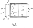
- spaced tie rods in the form of bolts 34 are provided in the area of the weld seam between the cover 10 and the side walls 22 and 24 ( Fig. 2 and Fig. 3 ).
- the bolts 34 are welded to the cover 10 and can be used as simple socket pins or but also be designed as a threaded bolt. Although the bolts 34 are not screwed, a design as a threaded bolt would increase the friction between the bolt and the adjacent component and thus ensure particularly good power transmission.
- a profile rail 36, 38 is welded to both side walls 22 and 24 of the housing 12, which extends at right angles to its side wall and which has a total of four bores 40 which are used for inserting the tie rods 34.
- the axis of each bore 40 runs parallel to the adjacent wall 22 and 24.
- the bore 40 itself can be designed as an elongated hole, the transverse extension of which is adapted to the cross section of the bolts 34 and is oriented at right angles to the adjacent side wall 22 and 24. This allows manufacturing and manufacturing tolerances in (in Fig. 1 and 2 ) compensate vertical direction. At the same time, however, the bolts 34 are in the bores 40 in the illustration of FIG Fig. 3 recorded with almost no play.
- the bolts 34 acting as tie rods in the bores 40 prevent the side walls 22 and 24 from bulging in the area of the weld, since the bolts 34 in the bores 40 of the profiles 36 and 38 are inserted.
- the reference numerals 42 and 44 denote U-shaped reinforcing rails which are applied to the outside of the housing 12.
- the reference numeral 46 denotes reinforcement profiles of the same type, which are welded onto the outside of the cover 10. Similar reinforcement profiles 48 are located on a cable connection container 50 which is provided on the underside of the housing 12.
Abstract
Ein gasisolierter Behälter für eine Schalteinrichtung der Mittelspannungstechnik umfasst ein von einem Deckel (10) verschlossenes Gehäuse (12), wobei im Bereich einer Schweißnaht zwischen Deckel (10) und Wand (22-28) zumindest ein Zuganker (34) vorgesehen ist.A gas-insulated container for a switching device in medium-voltage technology comprises a housing (12) closed by a cover (10), at least one tie rod (34) being provided in the area of a weld between the cover (10) and the wall (22-28).
Description
Die vorliegende Erfindung betrifft einen gasisolierten Behälter für eine Schalteinrichtung der Mittelspannungstechnik nach dem Oberbegriff des Anspruchs 1.The present invention relates to a gas-insulated container for a switching device in medium-voltage technology according to the preamble of claim 1.
Derartige gasisolierte Behälter unterliegen einem definierten Innendruck, der je nach Anforderung eine hohe Belastung des Materials und insbesondere der vorhandenen Schweißnaht bedeuten kann. So kann es bei einer hohen Druckbelastung zu einer Verformung der Wand und/oder des Deckels des Gehäuses kommen, so dass die Gefahr besteht, dass die vorhandene Schweißnaht aufgrund einer Verformung des Gehäuses undicht wird oder aufreißt.Such gas-insulated containers are subject to a defined internal pressure which, depending on the requirements, can mean a high load on the material and in particular on the existing weld seam. In the event of a high pressure load, the wall and / or the cover of the housing can be deformed, so that there is a risk that the existing weld seam will leak or tear due to deformation of the housing.
Es ist die Aufgabe der vorliegenden Erfindung, einen gasisolierten Behälter nach dem Oberbegriff des Anspruchs 1 derart weiterzubilden, dass auch bei erhöhter Druckbelastung eine Beschädigung der Schweißnaht unterbleibt.It is the object of the present invention to develop a gas-insulated container according to the preamble of claim 1 in such a way that damage to the weld seam does not occur even in the event of increased pressure load.
Die Lösung dieser Aufgabe erfolgt durch die Merkmale des Anspruchs 1 und insbesondere dadurch, dass im Bereich der Schweißnaht zwischen Deckel und Wand zumindest ein Zuganker vorgesehen ist.This object is achieved by the features of claim 1 and in particular in that at least one tie rod is provided in the area of the weld seam between the cover and the wall.
Mit Hilfe eines derartigen Zugankers kann die Kraft, die durch ein Verformen bzw. Ausbauchen einer Gehäusewand auf die Schweißnaht ausgeübt wird, zuverlässig aufgenommen werden, so dass die Schweißnaht nicht mehr oder nur noch geringfügig belastet wird.With the aid of such a tie rod, the force exerted on the weld seam by deforming or bulging a housing wall can be reliably absorbed, so that the weld seam is no longer or only slightly loaded.
Vorteilhafte Ausführungsformen der Erfindung sind in der Beschreibung, der Zeichnung sowie den Unteransprüchen beschrieben.Advantageous embodiments of the invention are described in the description, the drawing and the subclaims.
Nach einer ersten vorteilhaften Ausführungsform kann der Zuganker einen an dem Deckel starr befestigten Bolzen umfassen. Dies stellt eine kostengünstige und einfache Möglichkeit dar, die auftretenden Kräfte zuverlässig aufzunehmen.According to a first advantageous embodiment, the tie rod can comprise a bolt rigidly attached to the cover. This is an inexpensive and simple way of reliably absorbing the forces that occur.
Nach einer weiteren vorteilhaften Ausführungsform kann der Zuganker an dem Deckel verschweißt sein. Eine solche Befestigungsart ermöglicht einerseits eine gute Kraftübertragung. Andererseits muss keine weitere Abdichtung erfolgen, da der Zuganker nicht durch eine Öffnung oder dergleichen durch den Deckel hindurchgeführt ist.According to a further advantageous embodiment, the tie rod can be welded to the cover. On the one hand, such a type of fastening enables good power transmission. On the other hand, no further sealing has to take place, since the tie rod is not passed through an opening or the like through the cover.
Nach einer weiteren vorteilhaften Ausführungsform kann der Zuganker in eine Bohrung eingesteckt sein. Das Einstecken des Zugankers bzw. eines Bolzens zur Montage ermöglicht einen besonders zeitsparenden Zusammenbau des Behälters, da der Deckel vor dem Verschweißen lediglich auf den Behälter aufgesetzt werden muss und hierbei gleichzeitig der Zuganker in die Bohrung des Gehäuses eingesteckt werden kann, um die auftretenden Kräfte aufzunehmen.According to a further advantageous embodiment, the tie rod can be inserted into a bore. Inserting the tie rod or a bolt for assembly enables particularly time-saving assembly of the container, since the cover only needs to be placed on the container before welding and the tie rod can be inserted into the bore of the housing at the same time to absorb the forces that occur .
Nach einer weiteren vorteilhaften Ausführungsform kann die Bohrung in einem Profil ausgebildet sein, das im Bereich der Schweißnaht an der Wand befestigt, insbesondere verschweißt ist. Ein solches Profil mit Bohrungen lässt sich auf einfache Weise herstellen und mit derjenigen Wand verbinden, an der die Schweißnaht angeordnet ist. Wenn hierbei die Achse der Bohrung parallel zu dieser Wand verläuft, lässt sich der Deckel durch einfaches Einstecken des Zugankers in die Bohrung montieren und anschließend verschweißen.According to a further advantageous embodiment, the bore can be formed in a profile which is fastened, in particular welded, to the wall in the area of the weld seam. Such a profile with bores can be produced in a simple manner and connected to that wall on which the weld seam is arranged. If the axis of the bore runs parallel to this wall, the cover can be installed by simply inserting the tie rod into the bore and then welded.
Nach einer weiteren vorteilhaften Ausführungsform kann die Bohrung als Langloch ausgebildet sein, dessen Quererstreckung rechtwinklig zur benachbarten Seitenwand orientiert ist. Durch die Ausbildung als Langloch lassen sich Montage- und Fertigungstoleranzen in einer Richtung parallel zur Schweißnaht kompensieren.According to a further advantageous embodiment, the bore can be designed as an elongated hole whose transverse extent is oriented at right angles to the adjacent side wall. By designing it as an elongated hole, assembly and manufacturing tolerances can be compensated for in a direction parallel to the weld seam.
Gleichzeitig kann jedoch der Zuganker im Wesentlichen spielfrei in der Bohrung gehalten werden, da die auf den Querschnitt des Zugankers angepasste Quererstreckung des Langlochs rechtwinklig zur Seitenwand orientiert ist.At the same time, however, the tie rod can be held in the bore essentially free of play, since the transverse extension of the elongated hole, which is adapted to the cross section of the tie rod, is oriented at right angles to the side wall.
Die Schweißnaht zur Befestigung des Deckels kann so ausgebildet sein, dass diese den Deckel mit vier benachbarten Wänden verbindet. Durch eine streifenförmige Ausbildung der Schweißnaht lässt sich eine besonders gute Verbindung erzielen.The weld seam for fastening the cover can be designed such that it connects the cover to four adjacent walls. A particularly good connection can be achieved through a strip-shaped design of the weld seam.
Nach einer weiteren vorteilhaften Ausführungsform können Zuganker nur im Bereich von zwei einander gegenüberliegenden Wänden vorgesehen sein. Wenn die dem Deckel benachbarten Wände des Behälters unterschiedlich groß sind, treten die größten Verformungen bei einer Druckbelastung im Bereich der flächenmäßig größten Wände auf und es kann in einem solchen Fall ausreichend sein, wenn nur im Bereich dieser Wände Zuganker vorgesehen werden.According to a further advantageous embodiment, tie rods can only be provided in the area of two opposing walls. If the walls of the container adjacent to the lid are of different sizes, the greatest deformations occur when there is a pressure load in the area of the largest walls in terms of area and it may be sufficient in such a case if tie rods are only provided in the area of these walls.
Nachfolgend wird die vorliegende Erfindung rein beispielhaft anhand einer vorteilhaften Ausführungsform und unter Bezugnahme auf die beigefügten Zeichnungen beschrieben. Es zeigen:
- Fig. 1
- eine perspektivische Rückansicht eines gasisolierten Behälters;
- Fig. 2
- eine perspektivische Vorderansicht des Behälters von
Fig. 1 ; und - Fig. 3
- einen Schnitt durch den Behälter von
Fig. 1 entlang der Linie A-A.
- Fig. 1
- a perspective rear view of a gas-insulated container;
- Fig. 2
- FIG. 3 is a front perspective view of the container of FIG
Fig. 1 ; and - Fig. 3
- a section through the container of
Fig. 1 along the line AA.
Das Gehäuse 12 besitzt einen grundsätzlich quaderförmigen Aufbau und ist aus vier Seitenwänden 22, 24, 26 und 28 sowie einer Vorderwand 30 zusammengesetzt, die gasdicht miteinander verbunden sind. Zum gasdichten Verschließen des Gehäuses 12 an seiner Rückseite dient der Deckel 10, der wie auch die anderen Bestandteile des Gehäuses aus Blech hergestellt ist und eine umlaufende Abkantung 32 aufweist.The
Wie insbesondere
Zum Schutz dieser Schweißnaht, die in den Figuren nicht dargestellt ist, sind im Bereich der Schweißnaht zwischen dem Deckel 10 und den Seitenwänden 22 und 24 beabstandete Zuganker in Form von Bolzen 34 vorgesehen (
Zur Aufnahme der Bolzen 34 ist an beiden Seitenwänden 22 und 24 des Gehäuses 12 jeweils eine Profilschiene 36, 38 angeschweißt, die sich rechtwinklig zu ihrer Seitenwand erstreckt und die insgesamt vier Bohrungen 40 aufweist, die für ein Einstecken der Zuganker 34 dienen. Hierbei verläuft die Achse jeder Bohrung 40 parallel zur benachbarten Wand 22 und 24. Die Bohrung 40 selbst kann als Langloch ausgebildet sein, dessen Quererstreckung an den Querschnitt der Bolzen 34 angepasst ist und rechtwinklig zur benachbarten Seitenwand 22 und 24 orientiert ist. Hierdurch lassen sich Herstellungs- und Fertigungstoleranzen in (in
In den Figuren bezeichnen die Bezugszeichen 42 und 44 U-förmige Verstärkungsschienen, die an der Außenseite des Gehäuses 12 aufgebracht sind. Mit dem Bezugszeichen 46 sind gleichartige Verstärkungsprofile bezeichnet, die auf die Außenseite des Deckels 10 aufgeschweißt sind. Gleichartige Verstärkungsprofile 48 befinden sich auf einem Kabelanschlussbehälter 50, der an der Unterseite des Gehäuses 12 vorgesehen ist.In the figures, the
Claims (10)
dadurch gekennzeichnet, dass
im Bereich der Schweißnaht zwischen Deckel (10) und Wand (22-28) zumindest ein Zuganker (34) vorgesehen ist.Gas-insulated container for a switching device in medium-voltage technology, comprising a housing (12) closed by a cover (10), the cover (10) being welded to at least one wall (22-28) of the housing (12) along a weld seam,
characterized in that
at least one tie rod (34) is provided in the area of the weld between the cover (10) and the wall (22-28).
dadurch gekennzeichnet, dass
der Zuganker einen an dem Deckel (10) starr befestigten Bolzen (34) umfasst.Container according to claim 1,
characterized in that
the tie rod comprises a bolt (34) rigidly attached to the cover (10).
dadurch gekennzeichnet, dass
der Zuganker (34) an dem Deckel (10) verschweißt ist.Container according to claim 1 or 2,
characterized in that
the tie rod (34) is welded to the cover (10).
dadurch gekennzeichnet, dass
der Zuganker (34) in eine Bohrung (40) eingesteckt ist.Container according to one of the preceding claims,
characterized in that
the tie rod (34) is inserted into a bore (40).
dadurch gekennzeichnet, dass
die Bohrung (40) in einem Profil (36, 38) ausgebildet ist, das an der Wand (22, 24) befestigt, insbesondere verschweißt ist.Container according to one of the preceding claims,
characterized in that
the bore (40) is formed in a profile (36, 38) which is attached, in particular welded, to the wall (22, 24).
dadurch gekennzeichnet, dass
die Achse der Bohrung (40) parallel zur benachbarten Wand (22, 24) verläuft.Container according to claim 5,
characterized in that
the axis of the bore (40) is parallel to the adjacent wall (22, 24).
dadurch gekennzeichnet, dass
die Bohrung (40) als Langloch ausgebildet ist, dessen Quererstreckung rechtwinklig zur benachbarten Seitenwand (22, 24) orientiert ist.Container according to one of the preceding claims 4-6,
characterized in that
the bore (40) is designed as an elongated hole, the transverse extent of which is oriented at right angles to the adjacent side wall (22, 24).
dadurch gekennzeichnet, dass
die Schweißnaht den Deckel (10) mit vier Wänden (22-28) verbindet.Container according to one of the preceding claims,
characterized in that
the weld seam connects the cover (10) to four walls (22-28).
dadurch gekennzeichnet, dass
die Schweißnaht streifenförmig ausgebildet ist.Container according to one of the preceding claims,
characterized in that
the weld seam is strip-shaped.
dadurch gekennzeichnet, dass
Zuganker (34) nur im Bereich von zwei einander gegenüber liegenden Wänden (22, 24) vorgesehen sind.Container according to one of the preceding claims,
characterized in that
Tie rods (34) are only provided in the area of two opposing walls (22, 24).
Applications Claiming Priority (1)
| Application Number | Priority Date | Filing Date | Title |
|---|---|---|---|
| DE102019114570.8A DE102019114570A1 (en) | 2019-05-29 | 2019-05-29 | Gas-insulated container |
Publications (1)
| Publication Number | Publication Date |
|---|---|
| EP3745548A1 true EP3745548A1 (en) | 2020-12-02 |
Family
ID=70285422
Family Applications (1)
| Application Number | Title | Priority Date | Filing Date |
|---|---|---|---|
| EP20167357.1A Pending EP3745548A1 (en) | 2019-05-29 | 2020-03-31 | Gas insulated container |
Country Status (3)
| Country | Link |
|---|---|
| EP (1) | EP3745548A1 (en) |
| CN (1) | CN112018653A (en) |
| DE (1) | DE102019114570A1 (en) |
Cited By (1)
| Publication number | Priority date | Publication date | Assignee | Title |
|---|---|---|---|---|
| WO2022167491A1 (en) * | 2021-02-05 | 2022-08-11 | Schneider Electric Industries Sas | Pressure vessel |
Citations (4)
| Publication number | Priority date | Publication date | Assignee | Title |
|---|---|---|---|---|
| EP0871269A1 (en) * | 1997-04-08 | 1998-10-14 | Gec Alsthom T & D Sa | Gas-tight, metal housing for an electric energy distribution unit |
| CN103401173A (en) * | 2013-07-30 | 2013-11-20 | 上海天灵开关厂有限公司 | Common mounting cabinet of gas-insulated breaker |
| CN206585262U (en) * | 2017-03-03 | 2017-10-24 | 南京海兴电网技术有限公司 | A kind of pull bar for preventing inflatable ring main unit gas tank from deforming |
| EP3483995A1 (en) * | 2017-11-14 | 2019-05-15 | ABB Schweiz AG | Medium voltage gas insulated switchgear with pressure reinforced compartment |
Family Cites Families (2)
| Publication number | Priority date | Publication date | Assignee | Title |
|---|---|---|---|---|
| DE3267148D1 (en) * | 1981-07-01 | 1985-12-05 | Gerhard Kg | Pressure tank |
| FR2969405A1 (en) * | 2010-12-15 | 2012-06-22 | Areva T & D Sas | ELECTRICAL CONNECTING DEVICE WITH GAS INSULATION WITH IMPROVED LIFETIME |
-
2019
- 2019-05-29 DE DE102019114570.8A patent/DE102019114570A1/en active Pending
-
2020
- 2020-03-31 EP EP20167357.1A patent/EP3745548A1/en active Pending
- 2020-05-12 CN CN202010396142.XA patent/CN112018653A/en active Pending
Patent Citations (4)
| Publication number | Priority date | Publication date | Assignee | Title |
|---|---|---|---|---|
| EP0871269A1 (en) * | 1997-04-08 | 1998-10-14 | Gec Alsthom T & D Sa | Gas-tight, metal housing for an electric energy distribution unit |
| CN103401173A (en) * | 2013-07-30 | 2013-11-20 | 上海天灵开关厂有限公司 | Common mounting cabinet of gas-insulated breaker |
| CN206585262U (en) * | 2017-03-03 | 2017-10-24 | 南京海兴电网技术有限公司 | A kind of pull bar for preventing inflatable ring main unit gas tank from deforming |
| EP3483995A1 (en) * | 2017-11-14 | 2019-05-15 | ABB Schweiz AG | Medium voltage gas insulated switchgear with pressure reinforced compartment |
Cited By (1)
| Publication number | Priority date | Publication date | Assignee | Title |
|---|---|---|---|---|
| WO2022167491A1 (en) * | 2021-02-05 | 2022-08-11 | Schneider Electric Industries Sas | Pressure vessel |
Also Published As
| Publication number | Publication date |
|---|---|
| DE102019114570A1 (en) | 2020-12-03 |
| CN112018653A (en) | 2020-12-01 |
Similar Documents
| Publication | Publication Date | Title |
|---|---|---|
| EP3008370B1 (en) | Pipe collar or clamp | |
| DE2556048A1 (en) | SKELETON FOR METAL CABINET | |
| EP1238222A2 (en) | Assembly rail formed out of at least one profile element | |
| DE2435545A1 (en) | EDGE PAIR OF A FLOOR TUNNEL | |
| DE102010035792A1 (en) | Frame legs for a cabinet frame | |
| EP2923135A1 (en) | Inner seal collar with improved locking mechanism | |
| DE102015112935A1 (en) | bumper assembly | |
| EP3745548A1 (en) | Gas insulated container | |
| EP2787264A1 (en) | Holding element for holding a baffle plate in an air duct | |
| DE102018126524B3 (en) | Cross member for the automotive industry | |
| DE19724136C2 (en) | Sealing pipe and cable entry | |
| DE202012104117U1 (en) | Bumper cross member assembly | |
| EP0135042B1 (en) | Gate valve device | |
| DE19828896C1 (en) | Seal for pivoting door or glazing panel in motor vehicle | |
| DE3001563C2 (en) | Burglar-resistant door leaf | |
| EP3273114B1 (en) | Device with a seal | |
| EP0461336A2 (en) | Method of making a pressure chamber resisting against internal detonations, and pressure chamber made by this method | |
| EP3611307A1 (en) | Rail system | |
| DE102014109130B4 (en) | sealing cap | |
| EP2762659B1 (en) | Assembly and repair device | |
| EP0976959A2 (en) | Sealed feedthrough of conduits through a wall or plate-like structure, especially for a rail vehicle | |
| DE2908778A1 (en) | BARRIER, IN PARTICULAR VALVE | |
| DE19906174C1 (en) | Seal for valve flaps in motor vehicle exhaust duct has polygonal seals with sliding steel sections reinforcing corners of polygonal section | |
| DE2062071A1 (en) | Steel tank for heating oil or the like | |
| DE3732152A1 (en) | Cladding for rectangular chimneys |
Legal Events
| Date | Code | Title | Description |
|---|---|---|---|
| PUAI | Public reference made under article 153(3) epc to a published international application that has entered the european phase |
Free format text: ORIGINAL CODE: 0009012 |
|
| STAA | Information on the status of an ep patent application or granted ep patent |
Free format text: STATUS: THE APPLICATION HAS BEEN PUBLISHED |
|
| AK | Designated contracting states |
Kind code of ref document: A1 Designated state(s): AL AT BE BG CH CY CZ DE DK EE ES FI FR GB GR HR HU IE IS IT LI LT LU LV MC MK MT NL NO PL PT RO RS SE SI SK SM TR |
|
| AX | Request for extension of the european patent |
Extension state: BA ME |
|
| STAA | Information on the status of an ep patent application or granted ep patent |
Free format text: STATUS: REQUEST FOR EXAMINATION WAS MADE |
|
| 17P | Request for examination filed |
Effective date: 20210531 |
|
| RBV | Designated contracting states (corrected) |
Designated state(s): AL AT BE BG CH CY CZ DE DK EE ES FI FR GB GR HR HU IE IS IT LI LT LU LV MC MK MT NL NO PL PT RO RS SE SI SK SM TR |
|
| STAA | Information on the status of an ep patent application or granted ep patent |
Free format text: STATUS: EXAMINATION IS IN PROGRESS |
|
| 17Q | First examination report despatched |
Effective date: 20221220 |