EP3745504B1 - Electrode material and battery - Google Patents
Electrode material and battery Download PDFInfo
- Publication number
- EP3745504B1 EP3745504B1 EP18902418.5A EP18902418A EP3745504B1 EP 3745504 B1 EP3745504 B1 EP 3745504B1 EP 18902418 A EP18902418 A EP 18902418A EP 3745504 B1 EP3745504 B1 EP 3745504B1
- Authority
- EP
- European Patent Office
- Prior art keywords
- solid electrolyte
- negative electrode
- electrode active
- electrode
- active material
- Prior art date
- Legal status (The legal status is an assumption and is not a legal conclusion. Google has not performed a legal analysis and makes no representation as to the accuracy of the status listed.)
- Active
Links
Images
Classifications
-
- H—ELECTRICITY
- H01—ELECTRIC ELEMENTS
- H01M—PROCESSES OR MEANS, e.g. BATTERIES, FOR THE DIRECT CONVERSION OF CHEMICAL ENERGY INTO ELECTRICAL ENERGY
- H01M4/00—Electrodes
- H01M4/02—Electrodes composed of, or comprising, active material
- H01M4/62—Selection of inactive substances as ingredients for active masses, e.g. binders, fillers
-
- H—ELECTRICITY
- H01—ELECTRIC ELEMENTS
- H01M—PROCESSES OR MEANS, e.g. BATTERIES, FOR THE DIRECT CONVERSION OF CHEMICAL ENERGY INTO ELECTRICAL ENERGY
- H01M4/00—Electrodes
- H01M4/02—Electrodes composed of, or comprising, active material
- H01M4/36—Selection of substances as active materials, active masses, active liquids
- H01M4/362—Composites
- H01M4/366—Composites as layered products
-
- H—ELECTRICITY
- H01—ELECTRIC ELEMENTS
- H01B—CABLES; CONDUCTORS; INSULATORS; SELECTION OF MATERIALS FOR THEIR CONDUCTIVE, INSULATING OR DIELECTRIC PROPERTIES
- H01B1/00—Conductors or conductive bodies characterised by the conductive materials; Selection of materials as conductors
- H01B1/06—Conductors or conductive bodies characterised by the conductive materials; Selection of materials as conductors mainly consisting of other non-metallic substances
-
- H—ELECTRICITY
- H01—ELECTRIC ELEMENTS
- H01M—PROCESSES OR MEANS, e.g. BATTERIES, FOR THE DIRECT CONVERSION OF CHEMICAL ENERGY INTO ELECTRICAL ENERGY
- H01M10/00—Secondary cells; Manufacture thereof
- H01M10/05—Accumulators with non-aqueous electrolyte
- H01M10/052—Li-accumulators
- H01M10/0525—Rocking-chair batteries, i.e. batteries with lithium insertion or intercalation in both electrodes; Lithium-ion batteries
-
- H—ELECTRICITY
- H01—ELECTRIC ELEMENTS
- H01M—PROCESSES OR MEANS, e.g. BATTERIES, FOR THE DIRECT CONVERSION OF CHEMICAL ENERGY INTO ELECTRICAL ENERGY
- H01M10/00—Secondary cells; Manufacture thereof
- H01M10/05—Accumulators with non-aqueous electrolyte
- H01M10/056—Accumulators with non-aqueous electrolyte characterised by the materials used as electrolytes, e.g. mixed inorganic/organic electrolytes
- H01M10/0561—Accumulators with non-aqueous electrolyte characterised by the materials used as electrolytes, e.g. mixed inorganic/organic electrolytes the electrolyte being constituted of inorganic materials only
- H01M10/0562—Solid materials
-
- H—ELECTRICITY
- H01—ELECTRIC ELEMENTS
- H01M—PROCESSES OR MEANS, e.g. BATTERIES, FOR THE DIRECT CONVERSION OF CHEMICAL ENERGY INTO ELECTRICAL ENERGY
- H01M10/00—Secondary cells; Manufacture thereof
- H01M10/05—Accumulators with non-aqueous electrolyte
- H01M10/056—Accumulators with non-aqueous electrolyte characterised by the materials used as electrolytes, e.g. mixed inorganic/organic electrolytes
- H01M10/0564—Accumulators with non-aqueous electrolyte characterised by the materials used as electrolytes, e.g. mixed inorganic/organic electrolytes the electrolyte being constituted of organic materials only
- H01M10/0565—Polymeric materials, e.g. gel-type or solid-type
-
- H—ELECTRICITY
- H01—ELECTRIC ELEMENTS
- H01M—PROCESSES OR MEANS, e.g. BATTERIES, FOR THE DIRECT CONVERSION OF CHEMICAL ENERGY INTO ELECTRICAL ENERGY
- H01M4/00—Electrodes
- H01M4/02—Electrodes composed of, or comprising, active material
- H01M4/13—Electrodes for accumulators with non-aqueous electrolyte, e.g. for lithium-accumulators; Processes of manufacture thereof
- H01M4/133—Electrodes based on carbonaceous material, e.g. graphite-intercalation compounds or CFx
-
- H—ELECTRICITY
- H01—ELECTRIC ELEMENTS
- H01M—PROCESSES OR MEANS, e.g. BATTERIES, FOR THE DIRECT CONVERSION OF CHEMICAL ENERGY INTO ELECTRICAL ENERGY
- H01M4/00—Electrodes
- H01M4/02—Electrodes composed of, or comprising, active material
- H01M4/36—Selection of substances as active materials, active masses, active liquids
- H01M4/58—Selection of substances as active materials, active masses, active liquids of inorganic compounds other than oxides or hydroxides, e.g. sulfides, selenides, tellurides, halogenides or LiCoFy; of polyanionic structures, e.g. phosphates, silicates or borates
- H01M4/583—Carbonaceous material, e.g. graphite-intercalation compounds or CFx
- H01M4/587—Carbonaceous material, e.g. graphite-intercalation compounds or CFx for inserting or intercalating light metals
-
- H—ELECTRICITY
- H01—ELECTRIC ELEMENTS
- H01M—PROCESSES OR MEANS, e.g. BATTERIES, FOR THE DIRECT CONVERSION OF CHEMICAL ENERGY INTO ELECTRICAL ENERGY
- H01M4/00—Electrodes
- H01M4/02—Electrodes composed of, or comprising, active material
- H01M2004/026—Electrodes composed of, or comprising, active material characterised by the polarity
- H01M2004/027—Negative electrodes
-
- H—ELECTRICITY
- H01—ELECTRIC ELEMENTS
- H01M—PROCESSES OR MEANS, e.g. BATTERIES, FOR THE DIRECT CONVERSION OF CHEMICAL ENERGY INTO ELECTRICAL ENERGY
- H01M4/00—Electrodes
- H01M4/02—Electrodes composed of, or comprising, active material
- H01M2004/026—Electrodes composed of, or comprising, active material characterised by the polarity
- H01M2004/028—Positive electrodes
-
- H—ELECTRICITY
- H01—ELECTRIC ELEMENTS
- H01M—PROCESSES OR MEANS, e.g. BATTERIES, FOR THE DIRECT CONVERSION OF CHEMICAL ENERGY INTO ELECTRICAL ENERGY
- H01M2300/00—Electrolytes
- H01M2300/0017—Non-aqueous electrolytes
- H01M2300/0065—Solid electrolytes
- H01M2300/0068—Solid electrolytes inorganic
- H01M2300/0071—Oxides
-
- H—ELECTRICITY
- H01—ELECTRIC ELEMENTS
- H01M—PROCESSES OR MEANS, e.g. BATTERIES, FOR THE DIRECT CONVERSION OF CHEMICAL ENERGY INTO ELECTRICAL ENERGY
- H01M2300/00—Electrolytes
- H01M2300/0017—Non-aqueous electrolytes
- H01M2300/0065—Solid electrolytes
- H01M2300/0068—Solid electrolytes inorganic
- H01M2300/008—Halides
-
- H—ELECTRICITY
- H01—ELECTRIC ELEMENTS
- H01M—PROCESSES OR MEANS, e.g. BATTERIES, FOR THE DIRECT CONVERSION OF CHEMICAL ENERGY INTO ELECTRICAL ENERGY
- H01M2300/00—Electrolytes
- H01M2300/0017—Non-aqueous electrolytes
- H01M2300/0065—Solid electrolytes
- H01M2300/0082—Organic polymers
-
- H—ELECTRICITY
- H01—ELECTRIC ELEMENTS
- H01M—PROCESSES OR MEANS, e.g. BATTERIES, FOR THE DIRECT CONVERSION OF CHEMICAL ENERGY INTO ELECTRICAL ENERGY
- H01M2300/00—Electrolytes
- H01M2300/0088—Composites
- H01M2300/0094—Composites in the form of layered products, e.g. coatings
-
- Y—GENERAL TAGGING OF NEW TECHNOLOGICAL DEVELOPMENTS; GENERAL TAGGING OF CROSS-SECTIONAL TECHNOLOGIES SPANNING OVER SEVERAL SECTIONS OF THE IPC; TECHNICAL SUBJECTS COVERED BY FORMER USPC CROSS-REFERENCE ART COLLECTIONS [XRACs] AND DIGESTS
- Y02—TECHNOLOGIES OR APPLICATIONS FOR MITIGATION OR ADAPTATION AGAINST CLIMATE CHANGE
- Y02E—REDUCTION OF GREENHOUSE GAS [GHG] EMISSIONS, RELATED TO ENERGY GENERATION, TRANSMISSION OR DISTRIBUTION
- Y02E60/00—Enabling technologies; Technologies with a potential or indirect contribution to GHG emissions mitigation
- Y02E60/10—Energy storage using batteries
Definitions
- the present disclosure relates to an electrode material for batteries and a battery.
- Patent Literature 1 discloses a battery using, as a solid electrolyte, a halide including indium. JP2014146458 , EP3076459 , US2014308572 , US2016013479 , and TOMITA Yet al, "Substitution effect of ionic conductivity in lithium ion conductor, LI"3INBR"6"-"xCL”x", SOLID STATE IONICS, NORTH HOLLAND PUB. COMPANY. AMSTERDAM; NL, NL, vol. 179, no. 21-26, pages 867 - 870 , disclose electrode materials.
- the present invention provides an electrode material in accordance with claim 1. Preferred embodiments are defined in claims 2 to 18. Further, the present invention provides a battery in accordance with claim 19. Preferred embodiments are defined in claims 20 to 23.
- the techniques disclosed here feature an electrode material including an electrode active material, a first solid electrolyte material, and a coating material, wherein the first solid electrolyte material includes Li, M, and X and does not include sulfur, where M includes at least one selected from the group consisting of metal elements other than Li and metalloid elements, and X is at least one selected from the group consisting of Cl, Br, and I; and the coating material is located on the surface of the electrode active material.
- the charge/discharge efficiency of the battery can be improved.
- the electrode material according to Embodiment 1 includes an electrode active material, a first solid electrolyte material, and a coating material.
- the first solid electrolyte material is a material represented by the following compositional formula (1): Li ⁇ M ⁇ X ⁇ Formula (1) where, ⁇ , ⁇ , and ⁇ are all values larger than 0.
- M includes at least one selected from the group consisting of metal elements other than Li and metalloid elements.
- X is at least one selected from the group consisting of Cl, Br, and I.
- the coating material is located on the surface of the electrode active material.
- the charge/discharge efficiency of the battery can be improved.
- Patent Literature 1 mentions that in an all-solid secondary battery including a solid electrolyte made of a compound including indium, the potential of the positive electrode active material relative to Li is preferably 3.9 V or less on average, the potential of the negative electrode active material relative to Li is preferably 0.7 V or less on average, and a film made of a degradation product by oxidative decomposition and reductive decomposition of the electrolyte is consequently well formed to provide good charge/discharge characteristics.
- layered transition metal oxides for general positive electrodes such as LiCoO 2 and LiNi 0.8 Co 0.15 Al 0.05 O 2
- general negative electrode active materials such as Li metal and carbon active materials
- the detailed mechanisms of the oxidative decomposition and the reductive decomposition are not clarified.
- a battery using a halide solid electrolyte i.e., first solid electrolyte material
- a halide solid electrolyte i.e., first solid electrolyte material
- the halide solid electrolyte is oxidatively decomposed during charging, and the charge/discharge efficiency of the battery is accordingly reduced, and the cause thereof lies in the oxidation of the halogen element included in the halide solid electrolyte.
- a battery using a halide solid electrolyte as a negative electrode material has a problem that, even if a negative electrode active material having a potential of 0.7 V or less relative to Li on average is used, the halide solid electrolyte is reductively decomposed during charging, and the charge/discharge efficiency of the battery is accordingly reduced, and the cause thereof lies in the reduction of the metal element included in the halide solid electrolyte.
- a side reaction of receiving electrons also by the halide solid electrolyte being in contact with the negative electrode active material is caused, and the charge is consumed by the side reaction.
- the charge/discharge efficiency is probably reduced as a result.
- a coating material lies between the electrode active material and the halide solid electrolyte. This coating material prevents giving and receiving of electrons by the halide solid electrolyte. Consequently, the side reaction of the halide solid electrolyte is not caused, and the charge/discharge efficiency can be improved.
- the "metalloid elements” are B, Si, Ge, As, Sb, and Te.
- the "metal elements” are all elements excluding hydrogen in groups 1 to 12 of the periodic table and all elements in groups 13 to 16 excluding B, Si, Ge, As, Sb, Te, C, N, P, O, S, and Se, i.e., refer to a group consisting of elements that can become cations when forming inorganic compounds with halogen compounds.
- M includes Y (yttrium).
- the first solid electrolyte material may include Y as a metal element.
- the ion conductivity of the first solid electrolyte material can be further improved. Consequently, the charge/discharge characteristics of the battery can be further improved.
- Me may be at least one selected from the group consisting of Mg, Ca, Sr, Ba, Zn, Sc, Al, Ga, Bi, Zr, Hf, Ti, Sn, Ta, and Nb.
- the ion conductivity of the first solid electrolyte material can be further improved.
- compositional formula (1) 2 ⁇ ⁇ / ⁇ ⁇ 2.4 may be satisfied.
- the ion conductivity of the first solid electrolyte material can be further improved. Consequently, the charge/discharge characteristics of the battery can be further improved.
- the ion conductivity of the first solid electrolyte material can be further improved. Consequently, the charge/discharge characteristics of the battery can be further improved.
- X may include Cl (chlorine).
- the ion conductivity of the first solid electrolyte material can be further improved. Consequently, the charge/discharge characteristics of the battery can be further improved.
- the first solid electrolyte material may be a material represented by the following compositional formula (A1). Li 6-3d Y d X 6 Formula (A1)
- compositional formula (A1) is two or more elements selected from the group consisting of Cl, Br, and I.
- 0 ⁇ d ⁇ 2 is satisfied.
- the ion conductivity of the first solid electrolyte material can be further improved. Consequently, the charge/discharge characteristics of the battery can be further improved.
- the first solid electrolyte material may be a material represented by the following compositional formula (A2). Li 3 YX 6 Formula (A2)
- X is two or more elements selected from the group consisting of Cl, Br, and I.
- the ion conductivity of the first solid electrolyte material can be further improved. Consequently, the charge/discharge characteristics of the battery can be further improved.
- the first solid electrolyte material may be a material represented by the following compositional formula (A3). Li 3-3 ⁇ Y 1+ ⁇ Cl 6 Formula (A3)
- compositional formula (A3) 0 ⁇ ⁇ ⁇ 0.15, is satisfied.
- the ion conductivity of the first solid electrolyte material can be further improved. Consequently, the charge/discharge characteristics of the battery can be further improved.
- the first solid electrolyte material may be a material represented by the following compositional formula (A4). Li 3-3 ⁇ Y 1+ ⁇ Br 6 Formula (A4)
- compositional formula (A4) 0 ⁇ ⁇ ⁇ 0.25 is satisfied.
- the ion conductivity of the first solid electrolyte material can be further improved. Consequently, the charge/discharge characteristics of the battery can be further improved.
- the first solid electrolyte material may be a material represented by the following compositional formula (A5). Li 3-3 ⁇ +a Y 1+ ⁇ -a Me a Cl 6-x-y Br x l y Formula (A5)
- Me is at least one element selected from the group consisting of Mg, Ca, Sr, Ba, and Zn.
- compositional formula (A5) the followings are satisfied: ⁇ 1 ⁇ ⁇ ⁇ 2 , 0 ⁇ a ⁇ 3 , 0 ⁇ 3 ⁇ 3 ⁇ + a , 0 ⁇ 1 + ⁇ ⁇ a , 0 ⁇ x ⁇ 6 , 0 ⁇ y ⁇ 6 , and x + y ⁇ 6 .
- the ion conductivity of the first solid electrolyte material can be further improved. Consequently, the charge/discharge characteristics of the battery can be further improved.
- the first solid electrolyte material may be a material represented by the following compositional formula (A6). Li 3-3 ⁇ Y 1+ ⁇ -a Me a Cl 6-x-y Br x I y Formula (A6)
- Me is at least one element selected from the group consisting of Al, Sc, Ga, and Bi.
- compositional formula (A6) the followings are satisfied: ⁇ 1 ⁇ ⁇ ⁇ 1 , 0 ⁇ a ⁇ 2 , 0 ⁇ 1 + ⁇ ⁇ a , 0 ⁇ x ⁇ 6 , 0 ⁇ y ⁇ 6 , and x + y ⁇ 6 .
- the ion conductivity of the first solid electrolyte material can be further improved. Consequently, the charge/discharge characteristics of the battery can be further improved.
- the first solid electrolyte material may be a material represented by the following compositional formula (A7). Li 3-3 ⁇ -a Y 1+ ⁇ -a Me a Cl 6-x-y Br x I y Formula (A7)
- Me is at least one element selected from the group consisting of Zr, Hf, and Ti.
- compositional formula (A7) the followings are satisfied: ⁇ 1 ⁇ ⁇ ⁇ 1 , 0 ⁇ a ⁇ 1.5 , 0 ⁇ 3 ⁇ 3 ⁇ ⁇ a , 0 ⁇ 1 + ⁇ ⁇ a , 0 ⁇ x ⁇ 6 , 0 ⁇ y ⁇ 6 , and x + y ⁇ 6 .
- the ion conductivity of the first solid electrolyte material can be further improved. Consequently, the charge/discharge characteristics of the battery can be further improved.
- the first solid electrolyte material may be a material represented by the following compositional formula (A8). Li 3-3 ⁇ -2a Y 1+ ⁇ -a Me a Cl 6-x-y Br x I y Formula (A8)
- Me is at least one element selected from the group consisting of Ta and Nb.
- compositional formula (A8) the followings are satisfied: ⁇ 1 ⁇ ⁇ ⁇ 1 , 0 ⁇ a ⁇ 1.2 , 0 ⁇ 3 ⁇ 3 ⁇ ⁇ 2 a , 0 ⁇ 1 + ⁇ ⁇ a , 0 ⁇ x ⁇ 6 , 0 ⁇ y ⁇ 6 , and x + y ⁇ 6 .
- the ion conductivity of the first solid electrolyte material can be further improved. Consequently, the charge/discharge characteristics of the battery can be further improved.
- Li 3 YX 6 Li 2 MgX 4 , Li 2 FeX 4 , Li(Al, Ga, In)X 4 , or Li 3 (Al, Ga, In)X 6 can be used.
- X includes at least one element selected from the group consisting of Cl, Br, and I.
- the electrode active material includes a positive electrode active material or a negative electrode active material.
- the electrode active material may include a negative electrode active material.
- the effect of suppressing the side reaction of the first solid electrolyte material by providing a coating layer is significant when the electrode active material includes a negative electrode active material and can further enhance the charge/discharge efficiency of the battery.
- the negative electrode active material may have characteristics of occluding and releasing a metal ion (e.g., lithium ion).
- a metal material, a carbon material, an oxide, a nitride, a tin compound, or a silicon compound can be used as the negative electrode active material.
- the metal material may be a single metal or may be an alloy.
- Examples of the metal material include lithium metal and lithium alloys.
- Examples of the carbon material include natural graphite, coke, graphitized carbon, carbon fiber, spherical carbon, artificial graphite, and amorphous carbon. From the viewpoint of capacity density, silicon (Si), tin (Sn), silicon compounds, and tin compounds can be suitably used.
- the negative electrode active material may be graphite.
- the cycle performance, the energy density, and the charge/discharge efficiency of the battery can be further enhanced.
- the positive electrode active material may have characteristics of occluding and releasing a metal ion (e.g., lithium ion).
- a metal ion e.g., lithium ion
- a lithium-containing transition metal oxide e.g., Li(NiCoAl)O 2 , Li(NiCoMn)O 2 , or LiCoO 2
- a transition metal fluoride e.g., Li(NiCoAl)O 2 , Li(NiCoMn)O 2 , or LiCoO 2
- a transition metal fluoride e.g., Li(NiCoAl)O 2 , Li(NiCoMn)O 2 , or LiCoO 2
- a transition metal fluoride e.g., Li(NiCoAl)O 2 , Li(NiCoMn)O 2 , or LiCoO 2
- a transition metal fluoride e.g., Li(NiCoAl)O
- the coating material a material having low electron conductivity can be used.
- a sulfide solid electrolyte, a polymer solid electrolyte, or an oxide material can be used.
- Li 2 S-P 2 S 5 Li 2 S-SiS 2 , Li 2 S-B 2 S 3 , Li 2 S-GeS 2 , Li 3.25 Ge 0.25 P 0.75 S 4 , or Li 10 GeP 2 S 12
- LiX X: F, Cl, Br, or I
- Li 2 O, MO q Li 2 O, MO q
- Li p MO q Li p MO q (M: any one of P, Si, Ge, B, AI, Ga, In, Fe, and Zn) (p, q: natural number) may be added to the above-mentioned sulfide solid electrolytes.
- the coating material may be a sulfide solid electrolyte.
- the sulfide solid electrolyte may include lithium sulfide and phosphorus sulfide.
- sulfide solid electrolyte may be Li 2 S-P 2 S 5 .
- Li 2 S-P 2 S 5 has high ion conductivity and is stable against oxidation and reduction. Accordingly, the charge/discharge efficiency of the battery can be further improved by using Li 2 S-P 2 S 5 .
- the polymer solid electrolyte for example, a composite compound of a polymer compound and a lithium salt can be used.
- the polymer compound may have an ethylene oxide structure.
- a polymer compound having an ethylene oxide structure can contain a large amount of the lithium salt and can further enhance the ion conductivity.
- LiPF 6 , LiBF 4 , LiSbF 6 , LiAsF 6 , LiSOsCFs (hereinafter, referred to as LiTFS), LiN(SO 2 F) 2 (hereinafter, referred to as LiFSI), LiN(SO 2 CF 3 ) 2 (hereinafter, referred to as LiTFSI), LiN(SO 2 C 2 F 5 ) 2 , LiN(SO 2 CF 3 )(SO 2 C 4 F 9 ), or LiC(SO 2 CF 3 ) 3
- LiTFS LiN(SO 2 F) 2
- LiFSI LiN(SO 2 F) 2
- LiTFSI LiN(SO 2 C 2 F 5 ) 2
- LiN(SO 2 CF 3 )(SO 2 C 4 F 9 ) LiC(SO 2 CF 3 ) 3
- Li salt one lithium salt selected from the above may be used alone.
- a mixture of two or more lithium salts selected from the above may be used.
- the coating material may be a polymer solid electrolyte.
- the polymer solid electrolyte may be a composite compound of polyethylene oxide (PEO) and a lithium salt.
- the lithium salt may be lithium bis(trifluoromethanesulfonyl)imide (i.e., LiFSI).
- the PEO-LiFSI composite compound has high ion conductivity and is stable against oxidation and reduction. Accordingly, the charge/discharge efficiency of the battery can be further improved by using PEO-LiFSI.
- oxide material for example, SiO 2 , Al 2 O 3 , TiO 2 , B 2 O 3 , Nb 2 O 5 , WO 3 , or ZrO 2 can be used.
- the oxide material may be an oxide solid electrolyte or oxynitride solid electrolyte having lithium ion conductivity.
- the oxide solid electrolyte for example, a Li-P-O compound such as Li 3 PO 4 , a Li-Nb-O compound such as LiNbO 3 , a Li-B-O compound such as LiBO 2 or Li 3 BO 3 , a Li-AI-O compound such as LiAIO 2 , a Li-Si-O compound such as Li 4 SiO 4 , a Li-Ti-O compound such as Li 2 SO 4 or Li 4 Ti 5 O 12 , a Li-Zr-O compound such as Li 2 ZrO 3 , a Li-Mo-O compound such as Li 2 MoO 3 , a Li-V-O compound such as LiV 2 O 5 , or a Li-W-O compound such as Li 2 WO 4 can be used.
- the oxynitride solid electrolyte for example, a Li-P-
- the coating material may be an oxide solid electrolyte.
- the oxide solid electrolyte may be trilithium phosphate.
- Trilithium phosphate has high ion conductivity and is stable against oxidation and reduction. Accordingly, the charge/discharge efficiency of the battery can be further improved by using trilithium phosphate.
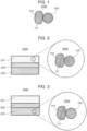
- Fig. 1 is a cross-sectional view illustrating a schematic configuration of an electrode material 1000 according to Embodiment 1.
- the electrode material 1000 in Embodiment 1 includes a first solid electrolyte particle 100, an electrode active material particle 110, and a coating layer 111.
- the electrode active material particle 110 and the first solid electrolyte particle 100 are separated from each other by the coating layer 111 and are not in direct contact with each other.
- the coating layer 111 is a layer including a coating material. That is, the coating layer 111 is provided on the surface of the electrode active material particle 110.
- the coating layer 111 may have a thickness of 1 nm or more and 100 nm or less.
- the coating layer 111 has a thickness of 1 nm or more, it is possible to prevent the electrode active material particle 110 and the first solid electrolyte particle 100 from direct contact to suppress the side reaction of the first solid electrolyte material. Consequently, the charge/discharge efficiency can be improved.
- the coating layer 111 has a thickness of 100 nm or less, the thickness of the coating layer 111 does not become too large. Accordingly, the internal resistance of the battery can be sufficiently reduced. As a result, the energy density of the battery can be increased.
- the coating layer 111 may uniformly coat the electrode active material particle 110. Direct contact between the electrode active material particle 110 and the first solid electrolyte particle 100 can be prevented to suppress the side reaction of the first solid electrolyte material. Consequently, the charge/discharge efficiency can be improved.
- the coating layer 111 may partially coat the electrode active material particle 110.
- a plurality of the electrode active material particles 110 are in direct contact with each other via the portion where the coating layer 111 is not present to improve the electron conductivity between the electrode active material particles 110. Consequently, high power operation of the battery is possible.
- the shape of the first solid electrolyte particle 100 in Embodiment 1 is not particularly limited and may be, for example, needle-like, spherical, or elliptical spherical.
- the median size may be 100 ⁇ m or less.
- the electrode active material particle 110 and the first solid electrolyte particle 100 can form a good dispersion state in the electrode material. Consequently, the charge/discharge characteristics is improved.
- the median size may be 10 ⁇ m or less.
- the electrode active material particle 110 and the first solid electrolyte particle 100 can form a good dispersion state.
- the first solid electrolyte particle 100 may be smaller than the median size of the electrode active material particle 110.
- the first solid electrolyte particle 100 and the electrode active material particle 110 can form a better dispersion state.
- the median size of the electrode active material particle 110 may be 0.1 ⁇ m or more and 100 ⁇ m or less.
- the electrode active material particle 110 has a median size of 0.1 ⁇ m or more, in the electrode material, the electrode active material particle 110 and the first solid electrolyte particle 100 can form a good dispersion state. As a result, the charge/discharge characteristics of the battery are improved. In addition, when the electrode active material particle 110 has a median size of 100 ⁇ m or less, the lithium diffusion in the electrode active material particle 110 is fast. Consequently, the battery can operate at high power.
- the median size of the electrode active material particle 110 may be larger than that of the first solid electrolyte particle 100. In such a case, the electrode active material particle 110 and the first solid electrolyte particle 100 can form a good dispersion state.
- the first solid electrolyte particle 100 and the coating layer 111 may be in contact with each other as shown in Fig. 1 .
- the electrode material 1000 in Embodiment 1 may include multiple first solid electrolyte particles 100 and multiple electrode active material particles 110.
- the content of the first solid electrolyte particle 100 and the content of the electrode active material particle 110 may be the same as or different from each other.
- the method for forming the coating layer 111 on the electrode active material particle 110 is not particularly limited.
- examples of the method include mechanical pulverization and mixing of the electrode active material particle 110 and the coating layer 111.
- the mixing method may be either a dry method or a wet method. In particular, dry mixing can simply produce a coating layer.
- the electrode active material particle 110 is dispersed in a coating material solution of the coating layer 111 and is dried.
- the coating layer can be simply and uniformly formed.
- examples of the method include an evaporation method.
- the evaporation method may be either a CVD method or a PVD method.
- ALD method atomic layer deposition method
- sputtering method which is one type of the PVD method
- the combination of the material used as the coating layer 111 and the method for forming it on the electrode active material particle 110 is not limited to the above-described examples, and the coating layer 111 may be formed by another combination.
- the first solid electrolyte material in Embodiment 1 can be manufactured by, for example, the following method.
- Raw material powders of binary halides are prepared so as to have the mix proportion of a desired composition.
- LiCI and YCl 3 are prepared at a mole ratio of 3:1.
- the raw material powders are mixed, pulverized, and reacted with each other by a mechanochemical milling method.
- the raw material powders are sufficiently mixed and may be then sintered.
- the configuration of the crystalline phase (i.e., crystalline structure) in the solid electrolyte material can be determined by adjusting the reaction method between the raw material powders and the reaction conditions.
- Embodiment 2 will now be described. Description overlapping with the above-described Embodiment 1 will be appropriately omitted.
- Fig. 2 is a cross-sectional view illustrating a schematic configuration of a battery 2000 according to Embodiment 2.
- Fig. 3 is a cross-sectional view illustrating a schematic configuration of a battery 3000 according to Embodiment 2.
- the battery 2000 in Embodiment 2 includes a positive electrode 201, an electrolyte layer 202, and a negative electrode 203.
- At least one of the positive electrode 201 and the negative electrode 203 includes the electrode material (e.g., electrode material 1000) in Embodiment 1 described above.
- Fig. 2 shows the battery 2000 in which the positive electrode 201 includes the electrode material 1000
- Fig. 3 shows the battery 3000 in which the negative electrode 203 includes the electrode material 1000.
- the electrolyte layer 202 is disposed between the positive electrode 201 and the negative electrode 203.
- the charge/discharge efficiency of the battery can be improved.
- the electrode material in Embodiment 1 described above can be used as a negative electrode material or a positive electrode material. More preferably, the electrode material in Embodiment 1 described above can be used as the negative electrode material.
- the charge/discharge efficiency of the battery can be further improved.
- the volume ratio, "v : 100 - v", of the electrode active material particle 110 and the first solid electrolyte particle 100 included in the positive electrode 201 may satisfy 30 ⁇ v ⁇ 95.
- v ⁇ 30 is satisfied, a sufficient energy density of the battery can be secured.
- v ⁇ 95 is satisfied, operation at high power can be realized.
- the volume ratio, "v : 100 - v" of the electrode active material particle 110 and the first solid electrolyte particle 100 included in the negative electrode 203 may satisfy 30 ⁇ v ⁇ 95.
- v ⁇ 30 is satisfied, a sufficient energy density of the battery can be secured.
- v ⁇ 95 is satisfied, operation at high power may be difficult.
- the positive electrode 201 may have a thickness of 10 ⁇ m or more and 500 ⁇ m or less. Further, when the positive electrode 201 has a thickness of 10 ⁇ m or more, a sufficient energy density of the battery can be secured. Further, when the positive electrode 201 has a thickness of 500 ⁇ m or less, operation at high power can be realized.
- the negative electrode 203 may have a thickness of 10 ⁇ m or more and 500 ⁇ m or less. Further, when the negative electrode 203 has a thickness of 10 ⁇ m or more, a sufficient energy density of the battery can be secured. Further, when the negative electrode 203 has a thickness of 500 ⁇ m or less, operation at high power can be realized.
- the electrolyte layer 202 is a layer including an electrolyte material.
- the electrolyte material is, for example, a solid electrolyte material (i.e., second solid electrolyte material). That is, the electrolyte layer 202 may be a solid electrolyte layer.
- a halide solid electrolyte As the second solid electrolyte material included in the electrolyte layer 202, a halide solid electrolyte, a sulfide solid electrolyte, an oxide solid electrolyte, a polymer solid electrolyte, or a complex hydride solid electrolyte may be used.
- the first solid electrolyte material in Embodiment 1 described above may be used. That is, the electrolyte layer 202 may include the first solid electrolyte material in Embodiment 1 described above.
- the charge/discharge characteristics of the battery can be further improved.
- the second solid electrolyte material included in the electrolyte layer 202 may be a halide solid electrolyte material that is different from the first solid electrolyte material in Embodiment 1 described above. That is, the electrolyte layer 202 may include a halide solid electrolyte material that is different from the first solid electrolyte material in Embodiment 1 described above.
- the charge/discharge characteristics of the battery can be further improved.
- the sulfide solid electrolyte As the sulfide solid electrolyte, the sulfide solid electrolytes exemplified as the coating material in Embodiment 1 may be used.
- Li 2 S-P 2 S 5 Li 2 S-SiS 2 , Li 2 S-B 2 S 3 , Li 2 S-GeS 2 , Li 3.25 Ge 0.25 P 0.75 S 4 , or Li 10 GeP 2 S 12
- LiX X: F, Cl, Br, or I
- Li 2 O, MO q Li 2 O, MO q
- Li p MO q Li p MO q (M: any one of P, Si, Ge, B, Al, Ga, In, Fe, and Zn) (p, q: natural number) may be added to the above-mentioned sulfide solid electrolytes.
- the oxide solid electrolyte As the oxide solid electrolyte, the oxide solid electrolytes exemplified as the coating material in Embodiment 1 may be used.
- oxide solid electrolyte for example, a NASICON-type solid electrolyte represented by LiTi 2 (PO 4 ) 3 and element substitutes thereof, a (LaLi)TiO 3 -based perovskite solid electrolyte, a LISICON-type solid electrolyte represented by Li 14 ZnGe 4 O 16 , Li 4 SiO 4 , and LiGeO 4 and element substitutes thereof, a garnet-type solid electrolyte represented by Li 7 La 3 Zr 2 O 12 and element substitutes thereof, Li 3 N and H substitutes thereof, Li 3 PO 4 and N substitutes thereof, or glass or glass ceramic mainly made of a Li-B-O compound, such as LiBO 2 or Li 3 BO 3 , and containing Li 2 SO 4 , Li 2 CO 3 , or the like can be used.
- a Li-B-O compound such as LiBO 2 or Li 3 BO 3 , and containing Li 2 SO 4 , Li 2 CO 3 , or the like
- the polymer solid electrolyte As the polymer solid electrolyte, the polymer solid electrolytes exemplified as the coating material in Embodiment 1 may be used.
- the polymer solid electrolyte for example, a compound of a polymer compound and a lithium salt may be used.
- the polymer compound may have an ethylene oxide structure.
- a polymer compound having an ethylene oxide structure can contain a large amount of the lithium salt and can further enhance the ion conductivity.
- the lithium salt for example, LiPF 6 , LiBF 4 , LiSbF 6 , LiAsF 6 , LiSO 3 CF 3 , LiN(SO 2 CF 3 ) 2 , LiN(SO 2 C 2 F 5 ) 2 , LiN(SO 2 CF 3 )(SO 2 C 4 F 9 ), or LiC(SO 2 CF 3 ) 3 can be used.
- the lithium salt one lithium salt selected from the above may be used alone.
- a mixture of two or more lithium salts selected from the above may be used.
- LiBH 4 -LiI or LiBH 4 -P 2 S 5 can be used as the complex hydride solid electrolyte.
- the solid electrolyte layer may include a second solid electrolyte material as a main component. That is, the solid electrolyte layer may include the second solid electrolyte material, for example, at 50% by weight or more (50 wt% or more) based on the entire solid electrolyte layer.
- the charge/discharge characteristics of the battery can be further improved.
- the solid electrolyte layer may include the second solid electrolyte material, for example, at 70% by weight or more (70 wt% or more) based on the entire solid electrolyte layer.
- the charge/discharge characteristics of the battery can be further improved.
- the solid electrolyte layer including the second solid electrolyte material as the main component may further include inevitable impurities or starting materials, by-products, decomposition products, etc. used or produced in synthesis of the second solid electrolyte material.
- the solid electrolyte layer may include the second solid electrolyte material, for example, at 100% by weight (100 wt%) based on the entire solid electrolyte layer excluding inevitable impurities as contamination.
- the charge/discharge characteristics of the battery can be further improved.
- the solid electrolyte layer may be constituted of the second solid electrolyte material only.
- the solid electrolyte layer may include two or more of the materials mentioned as the second solid electrolyte material.
- the solid electrolyte layer may include a halide solid electrolyte material and a sulfide solid electrolyte material.
- the electrolyte layer 202 may have a thickness of 1 ⁇ m or more and 300 ⁇ m or less. When the electrolyte layer 202 has a thickness of 1 ⁇ m or more, the positive electrode 201 and the negative electrode 203 can be separated from each other. In addition, when the electrolyte layer 202 has a thickness of 300 ⁇ m or less, operation at high power can be realized.
- the positive electrode 201 and the negative electrode 203 may include a solid electrolyte material.
- the solid electrolyte material the solid electrolyte materials exemplified as the material constituting the electrolyte layer 202 may be used. According to the configuration above, the lithium ion conductivity in the positive electrode 201 and the negative electrode 203 can be enhanced, and high power operation of the battery is possible.
- At least one of the positive electrode 201, the electrolyte layer 202, and the negative electrode 203 may include a binder for improving the adhesion between particles.
- the binder is used for improving the binding properties of the material constituting the electrode.
- the binder include polyvinylidene fluoride, polytetrafluoroethylene, polyethylene, polypropylene, aramid resin, polyamide, polyimide, polyamideimide, polyacrylnitrile, polyacrylic acid, polyacrylic acid methyl ester, polyacrylic acid ethyl ester, polyacrylic acid hexyl ester, polymethacrylic acid, polymethacrylic acid methyl ester, polymethacrylic acid ethyl ester, polymethacrylic acid hexyl ester, polyvinyl acetate, polyvinyl pyrrolidone, polyether, polyether sulfone, hexafluoropolypropylene, styrene butadiene rubber
- a copolymer of two or more materials selected from the group consisting of tetrafluoroethylene, hexafluoroethylene, hexafluoropropylene, perfluoroalkyl vinyl ether, vinylidene fluoride, chlorotrifluoroethylene, ethylene, propylene, pentafluoropropylene, fluoromethyl vinyl ether, acrylic acid, and hexadiene can be used.
- a mixture of two or more selected from the above may be used as the binder.
- At least one of the positive electrode 201 and the negative electrode 203 may include a conductive assistant for enhancing the electron conductivity.
- a conductive assistant for example, graphites such as natural graphite and artificial graphite, carbon blacks such as acetylene black and Ketjen black, conductive fibers such as carbon fiber and metal fiber, carbon fluoride, metal powders such as aluminum, conductive whiskers such as zinc oxide and potassium titanate, conductive metal oxides such as titanium oxide, and conductive polymer compounds such as polyaniline, polypyrrole, and polythiophene can be used.
- a carbon conductive assistant is used, cost reduction can be achieved.
- the battery in Embodiment 2 can be configured as batteries of various shapes such as a coin type, a cylindrical type, a square type, a sheet type, a button type, a flat type, and a stacked type.
- the operation temperature of the battery is not particularly limited and may be -50°C to 100°C.
- the ion conductivity of the coating material of the coating layer 111 is improved with an increase in temperature. In particular, the ion conductivity is dramatically improved at temperature not lower than the melting point of the coating material of the coating layer 111, and high power operation of the battery can be achieved.
- raw material powders of LiCI and YCl 3 were weighed such that the mole ratio of LiCI : YCl 3 was 2.7 : 1.1. Subsequently, the powders were subjected to milling treatment with a planetary ball mill (P-5 type, manufactured by Fritsch) at 600 rpm for 25 hours to obtain a powder of a first solid electrolyte material Li 2.7 Y 1.1 Cl 6 .
- a planetary ball mill P-5 type, manufactured by Fritsch
- Li 2 S and P 2 S 5 were weighed such that the mole ratio of Li 2 S : P 2 S 5 was 75 : 25. These compounds were pulverized and mixed in a mortar. Subsequently, the mixture was subjected to milling treatment with a planetary ball mill (P-7 type, manufactured by Fritsch) at 510 rpm for 10 hours to provide a vitrified solid electrolyte. The provided vitrified solid electrolyte was heated at 270°C in an inert atmosphere for 2 hours. Consequently, Li 2 S-P 2 S 5 , which was a glass-ceramic solid electrolyte, was provided.
- P-7 type manufactured by Fritsch
- Li 2 S-P 2 S 5 coating layer on a negative electrode active material graphite
- a coating material Li 2 S-P 2 S 5
- a negative electrode active material graphite
- the first solid electrolyte material and the coated negative electrode active material in the inventive example 1-1 were weighed such that the weight proportion of the negative electrode active material (graphite) was 40 wt%. These materials were mixed in an agate mortar to produce a negative electrode material of the inventive example 1-1.
- the coating material (Li 2 S-P 2 S 5 ) of the inventive example 1-1 and a negative electrode active material (graphite) were weighed at a weight ratio of 1 : 2. These materials were mixed in an agate mortar to provide a coated negative electrode active material.
- a negative electrode material of the inventive example 1-2 was provided by the same method as in the inventive example 1-1, except for the production of the negative electrode active material-coating layer.
- the coating material (Li 2 S-P 2 S 5 ) of the inventive example 1-1 and a negative electrode active material (graphite) were weighed at a weight ratio of 1 : 8. These materials were mixed in an agate mortar to provide a coated negative electrode active material.
- a negative electrode material of the inventive example 1-3 was provided by the same method as in the inventive example 1-1, except for the production of the negative electrode active material-coating layer.
- raw material powders of LiCI, YCl 3 , and ZrCl 4 were weighed such that the mole ratio of LiCI : YCl 3 : ZrCl 4 was 5 : 1 : 1. Subsequently, the powders were subjected to milling treatment with a planetary ball mill (P-5 type, manufactured by Fritsch) at 600 rpm for 25 hours to provide a powder of a first solid electrolyte material Li 2.5 Zr 0.5 Y 0.5 Cl 6 .
- P-5 type manufactured by Fritsch
- the first solid electrolyte material of the inventive example 1-4 and the coated negative electrode active material of the inventive example 1-1 were weighed such that the weight proportion of the negative electrode active material (graphite) was 40 wt%. These materials were mixed in an agate mortar to produce a negative electrode material of the inventive example 1-4.
- raw material powders of LiBr, Lil, YCl 3 , and YBr 3 were weighed such that the mole ratio of LiBr : LiI : YCl 3 : YBr 3 was 3 : 6 : 2 : 1. Subsequently, the powders were subjected to milling treatment with a planetary ball mill (P-5 type, manufactured by Fritsch) at 600 rpm for 25 hours to provide a powder of a first solid electrolyte material Li 3 YBr 2 Cl 2 I 2 .
- a planetary ball mill P-5 type, manufactured by Fritsch
- the first solid electrolyte material of the inventive example 1-5 and the coated negative electrode active material of the inventive example 1-1 were weighed such that the weight proportion of the negative electrode active material (graphite) was 40 wt%. These materials were mixed with an agate mortar to produce a negative electrode material of the inventive example 1-5.
- a negative electrode material of the comparative example 1-1 was provided by the same method as in the inventive example 1-1, except that the negative electrode active material-coating layer was not produced, and graphite on which the coating layer was not formed was used.
- a negative electrode material of the comparative example 1-2 was provided by the same method as in the inventive example 1-4, except that the negative electrode active material-coating layer was not produced, and graphite on which the coating layer was not formed was used.
- a negative electrode material of The comparative example 1-3 was prepared by the same method as in the inventive example 1-5, except that the negative electrode active material-coating layer was not produced, and graphite on which the coating layer was not formed was used.
- the negative electrode materials of the inventive examples 1-1 to 1-5 and The comparative examples 1-1 to 1-3 described above were evaluated using electrochemical cells.
- Li 2 S-P 2 S 5 and 12 mg of the negative electrode material were stacked in this order in an insulating outer cylinder, and then, were pressure-molded with a pressure of 370 MPa to provide a negative electrode and a solid electrolyte layer.
- a metal In (thickness: 200 ⁇ m), a metal Li (thickness: 300 ⁇ m), and a metal In (thickness: 200 ⁇ m) were stacked in this order on a surface of the solid electrolyte layer opposite to a surface in contact with the negative electrode, and then, were pressure-molded with a pressure of 80 MPa to form a bipolar electrochemical cell composed of the negative electrode (working electrode), the solid electrolyte layer, and a counter electrode.
- the electrochemical cell was tied up with four bolts from the top and the bottom to apply a surface pressure of 150 MPa to the layered product composed of the negative electrode (working electrode), the solid electrolyte layer, and the counter electrode.
- batteries of the inventive examples 1-1 to 1-5 and the comparative examples 1-1 to 1-3 described above were each produced.
- a charge/discharge test was performed using each of the batteries of the inventive examples 1-1 to 1-5 and The comparative examples 1-1 to 1-3 described above under the following conditions.
- the battery was placed in a thermostat of 25°C.
- Constant-current charging was performed at a current value of 70 ⁇ A, which was 0.04C rate (24-hour rate) to the theoretical capacity of the negative electrode active material (graphite). The charge was terminated when a charging capacity reached 360 mAh/g (97% of the theoretical capacity, 372 mAh/g, of graphite).
- the results of the inventive examples 1-1 to 1-5 and the comparative examples 1-1 to 1-3shown in Table 1 demonstrate that the charge/discharge efficiency of a battery is improved by including a first solid electrolyte material represented by a compositional formula: Li ⁇ M ⁇ X ⁇ , where ⁇ , ⁇ , and ⁇ are values larger than 0; M includes at least one of metal elements other than Li and metalloid elements; and X is one or more elements selected from the group consisting of Cl, Br, and I, and providing a coating layer including a coating material on the surface of a negative electrode active material.
- a first solid electrolyte material represented by a compositional formula: Li ⁇ M ⁇ X ⁇ , where ⁇ , ⁇ , and ⁇ are values larger than 0
- M includes at least one of metal elements other than Li and metalloid elements
- X is one or more elements selected from the group consisting of Cl, Br, and I, and providing a coating layer including a coating material on the surface of a negative
- raw material powders of LiCI and YCl 3 were weighed such that the mole ratio of LiCI : YCl 3 was 2.7 : 1.1. Subsequently, the powders were subjected to milling treatment with a planetary ball mill (P-5 type, manufactured by Fritsch) at 600 rpm for 25 hours to prepare a powder of a first solid electrolyte material Li 2.7 Y 1.1 Cl 6 .
- a planetary ball mill P-5 type, manufactured by Fritsch
- a polymer compound polyethylene oxide (PEO, molecular weight: 4 ⁇ 10 6 ) and a lithium salt LiCF 3 SO 3 (i.e., LiTFS) were weighed such that the mole ratio of ethylene oxide unit: lithium salt was 10 : 1.
- the mixture was dissolved in acetonitrile to produce a polymer electrolyte PEO-LiTFS composite solution.
- a coating material (PEO-LiTFS) and a negative electrode active material (graphite) were weighed at a weight ratio of 1 : 8, and the graphite was added to the polymer electrolyte solution, followed by dispersion with an ultrasonic disperser and then mixing with a planetary centrifugal mixer (ARE-310, manufactured by THINKY) at 1600 rpm for 3 minutes. The resulting product was spread on a petri dish and was vacuum-dried at 70°C for 1 hour to provide a coated negative electrode active material.
- the first solid electrolyte material and the coated negative electrode active material of the inventive example 2-1 were weighed such that the negative electrode active material (graphite) was 40 wt% of the total amount. These materials were mixed in an agate mortar to produce a negative electrode material of the inventive example 2-1.
- the coating material PEO-LiTFS
- a negative electrode active material graphite
- a negative electrode material of the inventive example 2-2 was prepared by the same method as in the inventive example 2-1, except for the production of the negative electrode active material-coating layer.
- the coating material PEO-LiTFS
- a negative electrode active material graphite
- a negative electrode material of the inventive example 2-3 was prepared by the same method as in the inventive example 2-1, except for the production of the negative electrode active material-coating layer.
- a polymer compound polyethylene oxide (PEO, molecular weight: 4 ⁇ 10 6 ) and a lithium salt LiN(SO 2 CF 3 ) 2 (i.e., LiTFSI) were weighed such that the mole ratio of ethylene oxide unit: lithium salt was 10 : 1.
- the mixture was dissolved in acetonitrile to produce a polymer electrolyte PEO-LiTFSI composite solution.
- a coating material (PEO-LiTFSI) and a negative electrode active material (graphite) were weighed at a weight ratio of 1 : 8, and the graphite was added to the polymer electrolyte solution, followed by dispersion with an ultrasonic disperser and then mixing with a planetary centrifugal mixer (ARE-310, manufactured by THINKY) at 1600 rpm for 3 minutes. The resulting product was spread on a petri dish and was vacuum-dried at 70°C for 1 hour to prepare a coated negative electrode active material.
- the first solid electrolyte material of the inventive example 2-1 and the coated negative electrode active material of the inventive example 2-4 were weighed such that the negative electrode active material (graphite) was 40 wt% of the total amount. These materials were mixed in an agate mortar to produce a negative electrode material of the inventive example 2-4.
- a polymer compound polyethylene oxide (PEO, molecular weight: 4 ⁇ 10 6 ) and a lithium salt LiN(SO 2 F) 2 (i.e., LiFSI) were weighed such that the mole ratio of ethylene oxide unit: lithium salt was 10 : 1.
- the mixture was dissolved in acetonitrile to produce a polymer electrolyte PEO-LiFSI composite solution.
- a coating material (PEO-LiFSI) and a negative electrode active material (graphite) were weighed at a weight ratio of 1 : 8, and the graphite was added to the polymer electrolyte solution, followed by dispersion with an ultrasonic disperser and then mixing with a planetary centrifugal mixer (ARE-310, manufactured by THINKY) at 1600 rpm for 3 minutes. The resulting product was spread on a petri dish and was vacuum-dried at 70°C for 1 hour to provide a coated negative electrode active material.
- the first solid electrolyte material of the inventive example 2-1 and the coated negative electrode active material of the inventive example 2-5 were weighed such that the negative electrode active material (graphite) was 40 wt% of the total amount. These materials were mixed in an agate mortar to produce a negative electrode material of the inventive example 2-5.
- raw material powders of LiCI, YCl 3 and ZrCl 4 were weighed such that the mole ratio of LiCI : YCl 3 : ZrCl 4 was 5 : 1 : 1. Subsequently, the powders were subjected to milling treatment with a planetary ball mill (P-5 type, manufactured by Fritsch) at 600 rpm for 25 hours to provide a powder of a first solid electrolyte material Li 2.5 Zr 0.5 Y 0.5 Cl 6 .
- P-5 type manufactured by Fritsch
- the first solid electrolyte material of the inventive example 2-6 and the coated negative electrode active material of the inventive example 2-5 were weighed such that the weight proportion of the negative electrode active material (graphite) was 40 wt%. These materials were mixed in an agate mortar to produce a negative electrode material of the inventive example 2-6.
- a negative electrode material of The comparative example 2-1 was provided by the same method as in the inventive example 2-1, except that the negative electrode active material-coating layer was not produced, and graphite on which the coating layer was not formed was used.
- a negative electrode material of The comparative example 2-2 was provided by the same method as in the inventive example 2-6, except that the negative electrode active material-coating layer was not produced, and graphite on which the coating layer was not formed was used.
- Li 2 S and P 2 S 5 were weighed such that the mole ratio of Li 2 S : P 2 S 5 was 75 : 25. These compounds were pulverized and mixed in a mortar. Subsequently, the mixture was subjected to milling treatment with a planetary ball mill (P-7 type, manufactured by Fritsch) at 510 rpm for 10 hours to provide a vitrified solid electrolyte. The provided vitrified solid electrolyte was heated at 270°C in an inert atmosphere for 2 hours. Consequently, Li 2 S-P 2 S 5 , which was a glass-ceramic solid electrolyte, was provided.
- P-7 type manufactured by Fritsch
- the negative electrode materials of the inventive examples 2-1 to 2-6 and The comparative examples 2-1 and 2-2 described above were evaluated using electrochemical cells.
- Li 2 S-P 2 S 5 and 12 mg of the negative electrode material were stacked in this order in an insulating outer cylinder, and then, were pressure-molded with a pressure of 370 MPa to provide a negative electrode and a solid electrolyte layer.
- a metal In (thickness: 200 ⁇ m), a metal Li (thickness: 300 ⁇ m), and a metal In (thickness: 200 ⁇ m) were stacked in this order on a surface of the solid electrolyte layer opposite to a surface in contact with the negative electrode, and then, were pressure-molded with a pressure of 80 MPa to form a bipolar electrochemical cell composed of the negative electrode (working electrode), the solid electrolyte layer, and a counter electrode.
- the electrochemical cell was tied up with four bolts from the top and the bottom to apply a surface pressure of 150 MPa to the layered product composed of the negative electrode (working electrode), the solid electrolyte layer, and the counter electrode.
- a surface pressure of 150 MPa to the layered product composed of the negative electrode (working electrode), the solid electrolyte layer, and the counter electrode.
- a charge/discharge test was performed using each of the batteries of the inventive examples 2-1 to 2-6 and the comparative examples 2-1 and 2-2 described above under the following conditions.
- the battery was placed in a thermostat of 70°C.
- Constant-current charging was performed at a current value of 70 ⁇ A, which was 0.04C rate (24-hour rate) to the theoretical capacity of the negative electrode active material (graphite). The charge was terminated when a charging capacity reached 360 mAh/g (97% of the theoretical capacity, 372 mAh/g, of graphite).
- the results of the inventive examples 2-1 to 2-6 and the comparative examples 2-1 to 2-2 shown in Table 2 demonstrate that the charge/discharge efficiency of a battery is improved by including a first solid electrolyte material represented by a compositional formula: Li ⁇ M ⁇ X ⁇ , where ⁇ , ⁇ , and ⁇ are values larger than 0; M includes at least one of metal elements other than Li and metalloid elements; and X is one or more elements selected from the group consisting of Cl, Br, and I, and providing a coating layer including a coating material on the surface of a negative electrode active material.
- a first solid electrolyte material represented by a compositional formula: Li ⁇ M ⁇ X ⁇ , where ⁇ , ⁇ , and ⁇ are values larger than 0; M includes at least one of metal elements other than Li and metalloid elements; and X is one or more elements selected from the group consisting of Cl, Br, and I, and providing a coating layer including a coating material on the surface of a negative electrode active
- raw material powders of LiCI and YCl 3 were weighed such that the mole ratio of LiCI : YCl 3 was 2.7 : 1.1. Subsequently, the powders were subjected to milling treatment with a planetary ball mill (P-5 type, manufactured by Fritsch) at 600 rpm for 25 hours to provide a powder of a first solid electrolyte material Li 2.7 Y 1.1 Cl 6 .
- a planetary ball mill P-5 type, manufactured by Fritsch
- a film of Li 3 PO 4 was formed on a surface of a negative electrode active material (natural graphite) by an atomic layer deposition method (ALD method) to obtain a coated negative electrode active material.
- the first solid electrolyte material of the inventive example 3-1 and the coated negative electrode active material (graphite on which the coating layer was formed) of the inventive example 3-1 were weighed at a weight ratio of 40 : 60. These materials were mixed in an agate mortar to produce a negative electrode material of the inventive example 3-1.
- a film of Li 4 Ti 5 O 12 (hereinafter, written as LTO) was formed on a surface of a negative electrode active material (natural graphite) by a sputtering method to obtain a coated negative electrode active material.
- a negative electrode material of the inventive example 3-2 was provided by the same method as in the inventive example 3-1, except for the production of the negative electrode active material-coating layer.
- a film of SiO 2 was formed on a surface of a negative electrode active material (natural graphite) by a sputtering method to obtain a coated negative electrode active material.
- a negative electrode material of the inventive example 3-3 was provided by the same method as in the inventive example 3-1, except for the production of the negative electrode active material-coating layer.
- a negative electrode material of the comparative example 3-1 was provided by the same method as in the inventive example 3-1, except that the negative electrode active material-coating layer was not produced, and natural graphite not provided with a coating layer was used.
- Li 2 S and P 2 S 5 were weighed such that the mole ratio of Li 2 S : P 2 S 5 was 75 : 25. These compounds were pulverized and mixed in a mortar. Subsequently, the mixture was subjected to milling treatment with a planetary ball mill (P-7 type, manufactured by Fritsch) at 510 rpm for 10 hours to provide a vitrified solid electrolyte. The resulting vitrified solid electrolyte was heated at 270°C in an inert atmosphere for 2 hours. Consequently, Li 2 S-P 2 S 5 , which was a glass-ceramic solid electrolyte, was provided.
- P-7 type manufactured by Fritsch
- the negative electrode materials of the inventive examples 3-1 to 3-3 and the comparative example 3-1 described above were evaluated using electrochemical cells.
- a metal In (thickness: 200 ⁇ m), a metal Li (thickness: 300 ⁇ m), and a metal In (thickness: 200 ⁇ m) were stacked in this order on a surface of the solid electrolyte layer opposite to a surface in contact with the negative electrode, and then, were pressure-molded with a pressure of 80 MPa to form a bipolar electrochemical cell composed of the negative electrode (working electrode), the solid electrolyte layer, and a counter electrode.
- the electrochemical cell was tied up with four bolts from the top and the bottom to apply a surface pressure of 150 MPa to the layered product composed of the negative electrode (working electrode), the solid electrolyte layer, and the counter electrode.
- batteries of the inventive examples 3-1 to 3-3 and the comparative example 3-1 described above were each produced.
- a charge/discharge test was performed using each of the batteries of the inventive examples 3-1 to 3-3 and the comparative example 3-1 described above under the following conditions.
- the battery was placed in a thermostat of 70°C.
- Constant-current charging was performed at a current value of 70 ⁇ A, which was 0.04C rate (24-hour rate). The charge was terminated when a charging capacity reached 360 mAh/g (97% of the theoretical capacity, 372 mAh/g, of graphite).
- the results of the inventive examples 3-1 to 3-3 and the comparative example 3-1 shown in Table 3 demonstrate that the charge/discharge efficiency of a battery is improved by including a first solid electrolyte material represented by a compositional formula: Li ⁇ M ⁇ X ⁇ , where ⁇ , ⁇ , and ⁇ are values larger than 0; M includes at least one of metal elements other than Li and metalloid elements; and X is one or more elements selected from the group consisting of Cl, Br, and I, and providing a coating layer including a coating material on a surface of a negative electrode active material.
- a first solid electrolyte material represented by a compositional formula: Li ⁇ M ⁇ X ⁇ , where ⁇ , ⁇ , and ⁇ are values larger than 0; M includes at least one of metal elements other than Li and metalloid elements; and X is one or more elements selected from the group consisting of Cl, Br, and I, and providing a coating layer including a coating material on a surface of a negative electrode active material
- the battery of the present disclosure can be used, for example, as an all-solid lithium secondary battery.
Landscapes
- Chemical & Material Sciences (AREA)
- Chemical Kinetics & Catalysis (AREA)
- Electrochemistry (AREA)
- General Chemical & Material Sciences (AREA)
- Engineering & Computer Science (AREA)
- Manufacturing & Machinery (AREA)
- Inorganic Chemistry (AREA)
- General Physics & Mathematics (AREA)
- Condensed Matter Physics & Semiconductors (AREA)
- Physics & Mathematics (AREA)
- Composite Materials (AREA)
- Materials Engineering (AREA)
- Dispersion Chemistry (AREA)
- Secondary Cells (AREA)
- Battery Electrode And Active Subsutance (AREA)
- Conductive Materials (AREA)
Description
- The present disclosure relates to an electrode material for batteries and a battery.
- Patent Literature 1 discloses a battery using, as a solid electrolyte, a halide including indium.
JP2014146458 EP3076459 ,US2014308572 ,US2016013479 , and TOMITA Yet al, "Substitution effect of ionic conductivity in lithium ion conductor, LI"3INBR"6"-"xCL"x", SOLID STATE IONICS, NORTH HOLLAND PUB. COMPANY. AMSTERDAM; NL, NL, vol. 179, no. 21-26, pages 867 - 870, disclose electrode materials. -
- Patent Literature 1:
Japanese Patent Application Publication No. 2006-244734 - Patent Literature 2:
Japanese Patent Application Publication No. 2016-207570 - In known techniques, it is desired to further improve the charge/discharge efficiency of a battery.
- The present invention provides an electrode material in accordance with claim 1. Preferred embodiments are defined in claims 2 to 18. Further, the present invention provides a battery in accordance with claim 19. Preferred embodiments are defined in claims 20 to 23. In one general aspect, the techniques disclosed here feature an electrode material including an electrode active material, a first solid electrolyte material, and a coating material, wherein the first solid electrolyte material includes Li, M, and X and does not include sulfur, where M includes at least one selected from the group consisting of metal elements other than Li and metalloid elements, and X is at least one selected from the group consisting of Cl, Br, and I; and the coating material is located on the surface of the electrode active material.
- According to the present disclosure, the charge/discharge efficiency of the battery can be improved.
-
-
Fig. 1 is a cross-sectional view illustrating a schematic configuration of anelectrode material 1000 according to Embodiment 1. -
Fig. 2 is a cross-sectional view illustrating a schematic configuration of abattery 2000 according to Embodiment 2. -
Fig. 3 is a cross-sectional view illustrating a schematic configuration of abattery 3000 according to Embodiment 2. - Embodiments of the present disclosure will now be described with reference to the drawings.
- The electrode material according to Embodiment 1 includes an electrode active material, a first solid electrolyte material, and a coating material.
- The first solid electrolyte material is a material represented by the following compositional formula (1):
LiαMβXγ Formula (1)
where, α, β, and γ are all values larger than 0. - M includes at least one selected from the group consisting of metal elements other than Li and metalloid elements.
- X is at least one selected from the group consisting of Cl, Br, and I.
- The coating material is located on the surface of the electrode active material.
- According to the above configuration, the charge/discharge efficiency of the battery can be improved.
- Patent Literature 1 mentions that in an all-solid secondary battery including a solid electrolyte made of a compound including indium, the potential of the positive electrode active material relative to Li is preferably 3.9 V or less on average, the potential of the negative electrode active material relative to Li is preferably 0.7 V or less on average, and a film made of a degradation product by oxidative decomposition and reductive decomposition of the electrolyte is consequently well formed to provide good charge/discharge characteristics. In addition, layered transition metal oxides for general positive electrodes, such as LiCoO2 and LiNi0.8Co0.15Al0.05O2, are disclosed as the positive electrode active material having a potential of 3.9 V or less relative to Li on average, and general negative electrode active materials, such as Li metal and carbon active materials, are disclosed as the negative electrode active material having a potential of 0.7 V or less relative to Li on average. In addition, the detailed mechanisms of the oxidative decomposition and the reductive decomposition are not clarified.
- In contrast, the present inventors intensively studied and, as a result, found that a battery using a halide solid electrolyte (i.e., first solid electrolyte material) as a positive electrode material has a problem that, even if a positive electrode active material having a potential of 3.9 V or less relative to Li on average is used, the halide solid electrolyte is oxidatively decomposed during charging, and the charge/discharge efficiency of the battery is accordingly reduced, and the cause thereof lies in the oxidation of the halogen element included in the halide solid electrolyte. Specifically, in addition to the normal charging reaction of extracting lithium and electrons from the positive electrode active material in the positive electrode material, a side reaction of extracting electrons also from the halide solid electrolyte being in contact with the positive electrode active material is caused, and the charge is consumed by the side reaction. Consequently, the charge/discharge efficiency is probably reduced.
- In addition, it is conceived that with the oxidation of the halide solid electrolyte, an oxidized layer having poor lithium ion conductivity is formed between the positive electrode active material and the halide solid electrolyte and functions as a large interface resistance in the electrode reaction of the positive electrode. In order to solve this problem, it is necessary to suppress the extraction of electrons by the halide solid electrolyte and to prevent the oxidized layer formation.
- In addition, it was found that a battery using a halide solid electrolyte as a negative electrode material has a problem that, even if a negative electrode active material having a potential of 0.7 V or less relative to Li on average is used, the halide solid electrolyte is reductively decomposed during charging, and the charge/discharge efficiency of the battery is accordingly reduced, and the cause thereof lies in the reduction of the metal element included in the halide solid electrolyte. Specifically, in addition to the normal charging reaction of inserting lithium into and receiving electrons by the negative electrode active material in the negative electrode material, a side reaction of receiving electrons also by the halide solid electrolyte being in contact with the negative electrode active material is caused, and the charge is consumed by the side reaction. The charge/discharge efficiency is probably reduced as a result. In order to solve this problem, it is necessary to suppress the receiving of electrons by the halide solid electrolyte and to prevent the reduced layer formation.
- In the configuration of the present disclosure, a coating material lies between the electrode active material and the halide solid electrolyte. This coating material prevents giving and receiving of electrons by the halide solid electrolyte. Consequently, the side reaction of the halide solid electrolyte is not caused, and the charge/discharge efficiency can be improved.
- Incidentally, the "metalloid elements" are B, Si, Ge, As, Sb, and Te.
- In addition, the "metal elements" are all elements excluding hydrogen in groups 1 to 12 of the periodic table and all elements in groups 13 to 16 excluding B, Si, Ge, As, Sb, Te, C, N, P, O, S, and Se, i.e., refer to a group consisting of elements that can become cations when forming inorganic compounds with halogen compounds.
- Further, in the compositional formula (1), M includes Y (yttrium).
- That is, the first solid electrolyte material may include Y as a metal element.
- According to the configuration above, the ion conductivity of the first solid electrolyte material can be further improved. Consequently, the charge/discharge characteristics of the battery can be further improved.
- The first solid electrolyte material including Y may be, for example, a compound represented by a compositional formula: LiaMebYcX6 (a + mb + 3c = 6 and c > 0 are satisfied) (Me: at least one of metal elements other than Li and Y and metalloid elements) (m: valence of Me).
- Me may be at least one selected from the group consisting of Mg, Ca, Sr, Ba, Zn, Sc, Al, Ga, Bi, Zr, Hf, Ti, Sn, Ta, and Nb.
- According to the configuration above, the ion conductivity of the first solid electrolyte material can be further improved.
- Further, in the compositional formula (1), 2 ≤ γ/α ≤ 2.4 may be satisfied.
- According to the configuration above, the ion conductivity of the first solid electrolyte material can be further improved. Consequently, the charge/discharge characteristics of the battery can be further improved.
- Further, in the compositional formula (1),


- Alternatively, in the compositional formula (1),


- Alternatively, in the compositional formula (1),


- According to the configuration above, the ion conductivity of the first solid electrolyte material can be further improved. Consequently, the charge/discharge characteristics of the battery can be further improved.
- Further, in the compositional formula (1), X may include Cl (chlorine).
- According to the configuration above, the ion conductivity of the first solid electrolyte material can be further improved. Consequently, the charge/discharge characteristics of the battery can be further improved.
- Further, the first solid electrolyte material may be a material represented by the following compositional formula (A1).
Li6-3dYdX6 Formula (A1)
- Here, in the compositional formula (A1), X is two or more elements selected from the group consisting of Cl, Br, and I. In addition, in the compositional formula (A1), 0 < d < 2 is satisfied.
- According to the configuration above, the ion conductivity of the first solid electrolyte material can be further improved. Consequently, the charge/discharge characteristics of the battery can be further improved.
- Further, the first solid electrolyte material may be a material represented by the following compositional formula (A2).
Li3YX6 Formula (A2)
- Here, in the compositional formula (A2), X is two or more elements selected from the group consisting of Cl, Br, and I.
- According to the configuration above, the ion conductivity of the first solid electrolyte material can be further improved. Consequently, the charge/discharge characteristics of the battery can be further improved.
- Further, the first solid electrolyte material may be a material represented by the following compositional formula (A3).
Li3-3δY1+δCl6 Formula (A3)
- Here, in the compositional formula (A3), 0 < δ ≤ 0.15, is satisfied.
- According to the configuration above, the ion conductivity of the first solid electrolyte material can be further improved. Consequently, the charge/discharge characteristics of the battery can be further improved.
- Further, the first solid electrolyte material may be a material represented by the following compositional formula (A4).
Li3-3δY1+δBr6 Formula (A4)
- Here, in the compositional formula (A4), 0 < δ ≤ 0.25 is satisfied.
- According to the configuration above, the ion conductivity of the first solid electrolyte material can be further improved. Consequently, the charge/discharge characteristics of the battery can be further improved.
- Further, the first solid electrolyte material may be a material represented by the following compositional formula (A5).
Li3-3δ+aY1+δ-aMeaCl6-x-yBrxly Formula (A5)
- Here, in the compositional formula (A5), Me is at least one element selected from the group consisting of Mg, Ca, Sr, Ba, and Zn.
- In addition, in the compositional formula (A5), the followings are satisfied:


- According to the configuration above, the ion conductivity of the first solid electrolyte material can be further improved. Consequently, the charge/discharge characteristics of the battery can be further improved.
- Further, the first solid electrolyte material may be a material represented by the following compositional formula (A6).
Li3-3δY1+δ-aMeaCl6-x-yBrxIy Formula (A6)
- Here, in the compositional formula (A6), Me is at least one element selected from the group consisting of Al, Sc, Ga, and Bi.
- In addition, in the compositional formula (A6), the followings are satisfied:


- According to the configuration above, the ion conductivity of the first solid electrolyte material can be further improved. Consequently, the charge/discharge characteristics of the battery can be further improved.
- Further, the first solid electrolyte material may be a material represented by the following compositional formula (A7).
Li3-3δ-aY1+δ-aMeaCl6-x-yBrxIy Formula (A7)
- Here, in the compositional formula (A7), Me is at least one element selected from the group consisting of Zr, Hf, and Ti.
- In addition, in the compositional formula (A7), the followings are satisfied:


- According to the configuration above, the ion conductivity of the first solid electrolyte material can be further improved. Consequently, the charge/discharge characteristics of the battery can be further improved.
- Further, the first solid electrolyte material may be a material represented by the following compositional formula (A8).
Li3-3δ-2aY1+δ-aMeaCl6-x-yBrxIy Formula (A8)
- Here, in the compositional formula (A8), Me is at least one element selected from the group consisting of Ta and Nb.
- In addition, in the compositional formula (A8), the followings are satisfied:


- According to the configuration above, the ion conductivity of the first solid electrolyte material can be further improved. Consequently, the charge/discharge characteristics of the battery can be further improved.
- Further, as the first solid electrolyte material, for example, Li3YX6, Li2MgX4, Li2FeX4, Li(Al, Ga, In)X4, or Li3(Al, Ga, In)X6 can be used. Here, X includes at least one element selected from the group consisting of Cl, Br, and I.
- The electrode active material includes a positive electrode active material or a negative electrode active material.
- The electrode active material may include a negative electrode active material.
- Further, the effect of suppressing the side reaction of the first solid electrolyte material by providing a coating layer is significant when the electrode active material includes a negative electrode active material and can further enhance the charge/discharge efficiency of the battery.
- The negative electrode active material may have characteristics of occluding and releasing a metal ion (e.g., lithium ion). As the negative electrode active material, for example, a metal material, a carbon material, an oxide, a nitride, a tin compound, or a silicon compound can be used. The metal material may be a single metal or may be an alloy. Examples of the metal material include lithium metal and lithium alloys. Examples of the carbon material include natural graphite, coke, graphitized carbon, carbon fiber, spherical carbon, artificial graphite, and amorphous carbon. From the viewpoint of capacity density, silicon (Si), tin (Sn), silicon compounds, and tin compounds can be suitably used.
- Further, in Embodiment 1, the negative electrode active material may be graphite.
- According to the configuration above, the cycle performance, the energy density, and the charge/discharge efficiency of the battery can be further enhanced.
- The positive electrode active material may have characteristics of occluding and releasing a metal ion (e.g., lithium ion). As the positive electrode active material, for example, a lithium-containing transition metal oxide (e.g., Li(NiCoAl)O2, Li(NiCoMn)O2, or LiCoO2), a transition metal fluoride, a polyanion or fluorinated polyanion material, a transition metal sulfide, a transition metal oxysulfide, or a transition metal oxynitride can be used. In particular, when the lithium-containing transition metal oxide is used as the positive electrode active material, the manufacturing cost can be reduced, and the average discharge voltage can be increased.
- As the coating material, a material having low electron conductivity can be used. As the coating material, for example, a sulfide solid electrolyte, a polymer solid electrolyte, or an oxide material can be used.
- As the sulfide solid electrolyte, for example, Li2S-P2S5, Li2S-SiS2, Li2S-B2S3, Li2S-GeS2, Li3.25Ge0.25P0.75S4, or Li10GeP2S12 can be used. In addition, for example, LiX (X: F, Cl, Br, or I), Li2O, MOq, or LipMOq (M: any one of P, Si, Ge, B, AI, Ga, In, Fe, and Zn) (p, q: natural number) may be added to the above-mentioned sulfide solid electrolytes.
- Further, in Embodiment 1, the coating material may be a sulfide solid electrolyte. For example, the sulfide solid electrolyte may include lithium sulfide and phosphorus sulfide. For example, sulfide solid electrolyte may be Li2S-P2S5.
- Li2S-P2S5 has high ion conductivity and is stable against oxidation and reduction. Accordingly, the charge/discharge efficiency of the battery can be further improved by using Li2S-P2S5.
- As the polymer solid electrolyte, for example, a composite compound of a polymer compound and a lithium salt can be used. The polymer compound may have an ethylene oxide structure. A polymer compound having an ethylene oxide structure can contain a large amount of the lithium salt and can further enhance the ion conductivity. As the lithium salt, for example, LiPF6, LiBF4, LiSbF6, LiAsF6, LiSOsCFs (hereinafter, referred to as LiTFS), LiN(SO2F)2 (hereinafter, referred to as LiFSI), LiN(SO2CF3)2 (hereinafter, referred to as LiTFSI), LiN(SO2C2F5)2, LiN(SO2CF3)(SO2C4F9), or LiC(SO2CF3)3 can be used. As the lithium salt, one lithium salt selected from the above may be used alone. Alternatively, as the lithium salt, a mixture of two or more lithium salts selected from the above may be used.
- Further, in Embodiment 1, the coating material may be a polymer solid electrolyte. For example, the polymer solid electrolyte may be a composite compound of polyethylene oxide (PEO) and a lithium salt. For example, the lithium salt may be lithium bis(trifluoromethanesulfonyl)imide (i.e., LiFSI).
- The PEO-LiFSI composite compound has high ion conductivity and is stable against oxidation and reduction. Accordingly, the charge/discharge efficiency of the battery can be further improved by using PEO-LiFSI.
- As the oxide material, for example, SiO2, Al2O3, TiO2, B2O3, Nb2O5, WO3, or ZrO2 can be used.
- Further, the oxide material may be an oxide solid electrolyte or oxynitride solid electrolyte having lithium ion conductivity. As the oxide solid electrolyte, for example, a Li-P-O compound such as Li3PO4, a Li-Nb-O compound such as LiNbO3, a Li-B-O compound such as LiBO2 or Li3BO3, a Li-AI-O compound such as LiAIO2, a Li-Si-O compound such as Li4SiO4, a Li-Ti-O compound such as Li2SO4 or Li4Ti5O12, a Li-Zr-O compound such as Li2ZrO3, a Li-Mo-O compound such as Li2MoO3, a Li-V-O compound such as LiV2O5, or a Li-W-O compound such as Li2WO4 can be used. As the oxynitride solid electrolyte, for example, a Li-P-O-N compound such as lithium phosphate oxynitride (LiPON) can be used.
- Further, in Embodiment 1, the coating material may be an oxide solid electrolyte. For example, the oxide solid electrolyte may be trilithium phosphate.
- Trilithium phosphate has high ion conductivity and is stable against oxidation and reduction. Accordingly, the charge/discharge efficiency of the battery can be further improved by using trilithium phosphate.
-
Fig. 1 is a cross-sectional view illustrating a schematic configuration of anelectrode material 1000 according to Embodiment 1. - The
electrode material 1000 in Embodiment 1 includes a firstsolid electrolyte particle 100, an electrodeactive material particle 110, and acoating layer 111. - The electrode
active material particle 110 and the firstsolid electrolyte particle 100 are separated from each other by thecoating layer 111 and are not in direct contact with each other. - The
coating layer 111 is a layer including a coating material. That is, thecoating layer 111 is provided on the surface of the electrodeactive material particle 110. - Further, the
coating layer 111 may have a thickness of 1 nm or more and 100 nm or less. - When the
coating layer 111 has a thickness of 1 nm or more, it is possible to prevent the electrodeactive material particle 110 and the firstsolid electrolyte particle 100 from direct contact to suppress the side reaction of the first solid electrolyte material. Consequently, the charge/discharge efficiency can be improved. - In addition, when the
coating layer 111 has a thickness of 100 nm or less, the thickness of thecoating layer 111 does not become too large. Accordingly, the internal resistance of the battery can be sufficiently reduced. As a result, the energy density of the battery can be increased. - Further, the
coating layer 111 may uniformly coat the electrodeactive material particle 110. Direct contact between the electrodeactive material particle 110 and the firstsolid electrolyte particle 100 can be prevented to suppress the side reaction of the first solid electrolyte material. Consequently, the charge/discharge efficiency can be improved. - Alternatively, the
coating layer 111 may partially coat the electrodeactive material particle 110. A plurality of the electrodeactive material particles 110 are in direct contact with each other via the portion where thecoating layer 111 is not present to improve the electron conductivity between the electrodeactive material particles 110. Consequently, high power operation of the battery is possible. - In addition, the shape of the first
solid electrolyte particle 100 in Embodiment 1 is not particularly limited and may be, for example, needle-like, spherical, or elliptical spherical. For example, when the shape of the firstsolid electrolyte particle 100 in Embodiment 1 is spherical, the median size may be 100 µm or less. When the median size is 100 µm or less, the electrodeactive material particle 110 and the firstsolid electrolyte particle 100 can form a good dispersion state in the electrode material. Consequently, the charge/discharge characteristics is improved. In addition, in Embodiment 1, the median size may be 10 µm or less. - According to the configuration above, in the electrode material, the electrode
active material particle 110 and the firstsolid electrolyte particle 100 can form a good dispersion state. - In addition, in Embodiment 1, the first
solid electrolyte particle 100 may be smaller than the median size of the electrodeactive material particle 110. - According to the configuration above, in the electrode, the first
solid electrolyte particle 100 and the electrodeactive material particle 110 can form a better dispersion state. - The median size of the electrode
active material particle 110 may be 0.1 µm or more and 100 µm or less. - When the electrode
active material particle 110 has a median size of 0.1 µm or more, in the electrode material, the electrodeactive material particle 110 and the firstsolid electrolyte particle 100 can form a good dispersion state. As a result, the charge/discharge characteristics of the battery are improved. In addition, when the electrodeactive material particle 110 has a median size of 100 µm or less, the lithium diffusion in the electrodeactive material particle 110 is fast. Consequently, the battery can operate at high power. - The median size of the electrode
active material particle 110 may be larger than that of the firstsolid electrolyte particle 100. In such a case, the electrodeactive material particle 110 and the firstsolid electrolyte particle 100 can form a good dispersion state. - Further, in the
electrode material 1000 according to Embodiment 1, the firstsolid electrolyte particle 100 and thecoating layer 111 may be in contact with each other as shown inFig. 1 . - In addition, the
electrode material 1000 in Embodiment 1 may include multiple firstsolid electrolyte particles 100 and multiple electrodeactive material particles 110. - In addition, in the
electrode material 1000 according to Embodiment 1, the content of the firstsolid electrolyte particle 100 and the content of the electrodeactive material particle 110 may be the same as or different from each other. - The method for forming the
coating layer 111 on the electrodeactive material particle 110 is not particularly limited. For example, when a sulfide solid electrolyte is used as thecoating layer 111, examples of the method include mechanical pulverization and mixing of the electrodeactive material particle 110 and thecoating layer 111. The mixing method may be either a dry method or a wet method. In particular, dry mixing can simply produce a coating layer. - When a polymer solid electrolyte is used as the
coating layer 111, for example, the electrodeactive material particle 110 is dispersed in a coating material solution of thecoating layer 111 and is dried. In such a method, the coating layer can be simply and uniformly formed. - When an oxide material is used as the
coating layer 111, examples of the method include an evaporation method. The evaporation method may be either a CVD method or a PVD method. For example, an atomic layer deposition method (ALD method), which is one type of the CVD method, or a sputtering method, which is one type of the PVD method, is used. However, the combination of the material used as thecoating layer 111 and the method for forming it on the electrodeactive material particle 110 is not limited to the above-described examples, and thecoating layer 111 may be formed by another combination. Method for manufacturing first solid electrolyte material - The first solid electrolyte material in Embodiment 1 can be manufactured by, for example, the following method.
- Raw material powders of binary halides are prepared so as to have the mix proportion of a desired composition. For example, when Li3YCl6 is produced, LiCI and YCl3 are prepared at a mole ratio of 3:1.
- On this occasion, "M", "Me", and "X" in the above-described compositional formula can be determined by selecting the types of the raw material powders. In addition, the above-described values "α", "β", "γ", "d", "δ", "a", "x", and "y" can be adjusted by adjusting the raw material, mix proportion, and synthesis process.
- After sufficient mixing of the raw material powders, the raw material powders are mixed, pulverized, and reacted with each other by a mechanochemical milling method. Alternatively, the raw material powders are sufficiently mixed and may be then sintered.
- Consequently, a solid electrolyte material including a crystalline phase as described above can be obtained.
- Further, the configuration of the crystalline phase (i.e., crystalline structure) in the solid electrolyte material can be determined by adjusting the reaction method between the raw material powders and the reaction conditions.
- Embodiment 2 will now be described. Description overlapping with the above-described Embodiment 1 will be appropriately omitted.
-
Fig. 2 is a cross-sectional view illustrating a schematic configuration of abattery 2000 according to Embodiment 2.Fig. 3 is a cross-sectional view illustrating a schematic configuration of abattery 3000 according to Embodiment 2. - The
battery 2000 in Embodiment 2 includes apositive electrode 201, anelectrolyte layer 202, and anegative electrode 203. - At least one of the
positive electrode 201 and thenegative electrode 203 includes the electrode material (e.g., electrode material 1000) in Embodiment 1 described above.Fig. 2 shows thebattery 2000 in which thepositive electrode 201 includes theelectrode material 1000, andFig. 3 shows thebattery 3000 in which thenegative electrode 203 includes theelectrode material 1000. - The
electrolyte layer 202 is disposed between thepositive electrode 201 and thenegative electrode 203. - According to the configuration above, the charge/discharge efficiency of the battery can be improved.
- Further, the electrode material in Embodiment 1 described above can be used as a negative electrode material or a positive electrode material. More preferably, the electrode material in Embodiment 1 described above can be used as the negative electrode material.
- According to the configuration above, the charge/discharge efficiency of the battery can be further improved.
- When the
positive electrode 201 includes theelectrode material 1000, the volume ratio, "v : 100 - v", of the electrodeactive material particle 110 and the firstsolid electrolyte particle 100 included in thepositive electrode 201 may satisfy 30 ≤ v ≤ 95. When v ≥ 30 is satisfied, a sufficient energy density of the battery can be secured. In addition, when v ≤ 95 is satisfied, operation at high power can be realized. - When the
negative electrode 203 includes theelectrode material 1000, the volume ratio, "v : 100 - v", of the electrodeactive material particle 110 and the firstsolid electrolyte particle 100 included in thenegative electrode 203 may satisfy 30 ≤ v ≤ 95. When v ≥ 30 is satisfied, a sufficient energy density of the battery can be secured. In addition, when v ≤ 95 is satisfied, operation at high power may be difficult. - The
positive electrode 201 may have a thickness of 10 µm or more and 500 µm or less. Further, when thepositive electrode 201 has a thickness of 10 µm or more, a sufficient energy density of the battery can be secured. Further, when thepositive electrode 201 has a thickness of 500 µm or less, operation at high power can be realized. - The
negative electrode 203 may have a thickness of 10 µm or more and 500 µm or less. Further, when thenegative electrode 203 has a thickness of 10 µm or more, a sufficient energy density of the battery can be secured. Further, when thenegative electrode 203 has a thickness of 500 µm or less, operation at high power can be realized. - The
electrolyte layer 202 is a layer including an electrolyte material. The electrolyte material is, for example, a solid electrolyte material (i.e., second solid electrolyte material). That is, theelectrolyte layer 202 may be a solid electrolyte layer. - As the second solid electrolyte material included in the
electrolyte layer 202, a halide solid electrolyte, a sulfide solid electrolyte, an oxide solid electrolyte, a polymer solid electrolyte, or a complex hydride solid electrolyte may be used. - As the halide solid electrolyte, the first solid electrolyte material in Embodiment 1 described above may be used. That is, the
electrolyte layer 202 may include the first solid electrolyte material in Embodiment 1 described above. - According to the configuration above, the charge/discharge characteristics of the battery can be further improved.
- In addition, the second solid electrolyte material included in the
electrolyte layer 202 may be a halide solid electrolyte material that is different from the first solid electrolyte material in Embodiment 1 described above. That is, theelectrolyte layer 202 may include a halide solid electrolyte material that is different from the first solid electrolyte material in Embodiment 1 described above. - According to the configuration above, the charge/discharge characteristics of the battery can be further improved.
- As the sulfide solid electrolyte, the sulfide solid electrolytes exemplified as the coating material in Embodiment 1 may be used.
- Specifically, as the sulfide solid electrolyte, for example, Li2S-P2S5, Li2S-SiS2, Li2S-B2S3, Li2S-GeS2, Li3.25Ge0.25P0.75S4, or Li10GeP2S12 can be used. In addition, for example, LiX (X: F, Cl, Br, or I), Li2O, MOq, or LipMOq (M: any one of P, Si, Ge, B, Al, Ga, In, Fe, and Zn) (p, q: natural number) may be added to the above-mentioned sulfide solid electrolytes.
- As the oxide solid electrolyte, the oxide solid electrolytes exemplified as the coating material in Embodiment 1 may be used.
- Specifically, as the oxide solid electrolyte, for example, a NASICON-type solid electrolyte represented by LiTi2(PO4)3 and element substitutes thereof, a (LaLi)TiO3-based perovskite solid electrolyte, a LISICON-type solid electrolyte represented by Li14ZnGe4O16, Li4SiO4, and LiGeO4 and element substitutes thereof, a garnet-type solid electrolyte represented by Li7La3Zr2O12 and element substitutes thereof, Li3N and H substitutes thereof, Li3PO4 and N substitutes thereof, or glass or glass ceramic mainly made of a Li-B-O compound, such as LiBO2 or Li3BO3, and containing Li2SO4, Li2CO3, or the like can be used.
- As the polymer solid electrolyte, the polymer solid electrolytes exemplified as the coating material in Embodiment 1 may be used.
- Specifically, as the polymer solid electrolyte, for example, a compound of a polymer compound and a lithium salt may be used. The polymer compound may have an ethylene oxide structure. A polymer compound having an ethylene oxide structure can contain a large amount of the lithium salt and can further enhance the ion conductivity. As the lithium salt, for example, LiPF6, LiBF4, LiSbF6, LiAsF6, LiSO3CF3, LiN(SO2CF3)2, LiN(SO2C2F5)2, LiN(SO2CF3)(SO2C4F9), or LiC(SO2CF3)3 can be used. As the lithium salt, one lithium salt selected from the above may be used alone. Alternatively, as the lithium salt, a mixture of two or more lithium salts selected from the above may be used.
- As the complex hydride solid electrolyte, for example, LiBH4-LiI or LiBH4-P2S5 can be used.
- Further, the solid electrolyte layer may include a second solid electrolyte material as a main component. That is, the solid electrolyte layer may include the second solid electrolyte material, for example, at 50% by weight or more (50 wt% or more) based on the entire solid electrolyte layer.
- According to the configuration above, the charge/discharge characteristics of the battery can be further improved.
- In addition, the solid electrolyte layer may include the second solid electrolyte material, for example, at 70% by weight or more (70 wt% or more) based on the entire solid electrolyte layer.
- According to the configuration above, the charge/discharge characteristics of the battery can be further improved.
- Further, the solid electrolyte layer including the second solid electrolyte material as the main component may further include inevitable impurities or starting materials, by-products, decomposition products, etc. used or produced in synthesis of the second solid electrolyte material.
- Further, the solid electrolyte layer may include the second solid electrolyte material, for example, at 100% by weight (100 wt%) based on the entire solid electrolyte layer excluding inevitable impurities as contamination.
- According to the configuration above, the charge/discharge characteristics of the battery can be further improved.
- As described above, the solid electrolyte layer may be constituted of the second solid electrolyte material only.
- Further, the solid electrolyte layer may include two or more of the materials mentioned as the second solid electrolyte material. For example, the solid electrolyte layer may include a halide solid electrolyte material and a sulfide solid electrolyte material.
- The
electrolyte layer 202 may have a thickness of 1 µm or more and 300 µm or less. When theelectrolyte layer 202 has a thickness of 1 µm or more, thepositive electrode 201 and thenegative electrode 203 can be separated from each other. In addition, when theelectrolyte layer 202 has a thickness of 300 µm or less, operation at high power can be realized. - The
positive electrode 201 and thenegative electrode 203 may include a solid electrolyte material. As the solid electrolyte material, the solid electrolyte materials exemplified as the material constituting theelectrolyte layer 202 may be used. According to the configuration above, the lithium ion conductivity in thepositive electrode 201 and thenegative electrode 203 can be enhanced, and high power operation of the battery is possible. - At least one of the
positive electrode 201, theelectrolyte layer 202, and thenegative electrode 203 may include a binder for improving the adhesion between particles. The binder is used for improving the binding properties of the material constituting the electrode. Examples of the binder include polyvinylidene fluoride, polytetrafluoroethylene, polyethylene, polypropylene, aramid resin, polyamide, polyimide, polyamideimide, polyacrylnitrile, polyacrylic acid, polyacrylic acid methyl ester, polyacrylic acid ethyl ester, polyacrylic acid hexyl ester, polymethacrylic acid, polymethacrylic acid methyl ester, polymethacrylic acid ethyl ester, polymethacrylic acid hexyl ester, polyvinyl acetate, polyvinyl pyrrolidone, polyether, polyether sulfone, hexafluoropolypropylene, styrene butadiene rubber, and carboxymethyl cellulose. In addition, as the binder, a copolymer of two or more materials selected from the group consisting of tetrafluoroethylene, hexafluoroethylene, hexafluoropropylene, perfluoroalkyl vinyl ether, vinylidene fluoride, chlorotrifluoroethylene, ethylene, propylene, pentafluoropropylene, fluoromethyl vinyl ether, acrylic acid, and hexadiene can be used. In addition, a mixture of two or more selected from the above may be used as the binder. - At least one of the
positive electrode 201 and thenegative electrode 203 may include a conductive assistant for enhancing the electron conductivity. As the conductive assistant, for example, graphites such as natural graphite and artificial graphite, carbon blacks such as acetylene black and Ketjen black, conductive fibers such as carbon fiber and metal fiber, carbon fluoride, metal powders such as aluminum, conductive whiskers such as zinc oxide and potassium titanate, conductive metal oxides such as titanium oxide, and conductive polymer compounds such as polyaniline, polypyrrole, and polythiophene can be used. When a carbon conductive assistant is used, cost reduction can be achieved. - Further, the battery in Embodiment 2 can be configured as batteries of various shapes such as a coin type, a cylindrical type, a square type, a sheet type, a button type, a flat type, and a stacked type.
- The operation temperature of the battery is not particularly limited and may be -50°C to 100°C. The ion conductivity of the coating material of the
coating layer 111 is improved with an increase in temperature. In particular, the ion conductivity is dramatically improved at temperature not lower than the melting point of the coating material of thecoating layer 111, and high power operation of the battery can be achieved. - The present disclosure will now be described in detail using examples and comparative examples but is not limited to the following examples.
- In an argon glove box having a dew point of -60°C or less, raw material powders of LiCI and YCl3 were weighed such that the mole ratio of LiCI : YCl3 was 2.7 : 1.1. Subsequently, the powders were subjected to milling treatment with a planetary ball mill (P-5 type, manufactured by Fritsch) at 600 rpm for 25 hours to obtain a powder of a first solid electrolyte material Li2.7Y1.1Cl6.
- In an argon glove box having a dew point of -60°C or less, Li2S and P2S5 were weighed such that the mole ratio of Li2S : P2S5 was 75 : 25. These compounds were pulverized and mixed in a mortar. Subsequently, the mixture was subjected to milling treatment with a planetary ball mill (P-7 type, manufactured by Fritsch) at 510 rpm for 10 hours to provide a vitrified solid electrolyte. The provided vitrified solid electrolyte was heated at 270°C in an inert atmosphere for 2 hours. Consequently, Li2S-P2S5, which was a glass-ceramic solid electrolyte, was provided.
- In the formation of a Li2S-P2S5 coating layer on a negative electrode active material (graphite), mixing in an agate mortar was performed. In an argon glove box, a coating material (Li2S-P2S5) and a negative electrode active material (graphite) were weighed at a weight ratio of 1 : 4. These materials were mixed in the agate mortar to obtain a coated negative electrode active material.
- In an argon glove box, the first solid electrolyte material and the coated negative electrode active material in the inventive example 1-1 were weighed such that the weight proportion of the negative electrode active material (graphite) was 40 wt%. These materials were mixed in an agate mortar to produce a negative electrode material of the inventive example 1-1.
- In an argon glove box, the coating material (Li2S-P2S5) of the inventive example 1-1 and a negative electrode active material (graphite) were weighed at a weight ratio of 1 : 2. These materials were mixed in an agate mortar to provide a coated negative electrode active material.
- A negative electrode material of the inventive example 1-2 was provided by the same method as in the inventive example 1-1, except for the production of the negative electrode active material-coating layer.
- In an argon glove box, the coating material (Li2S-P2S5) of the inventive example 1-1 and a negative electrode active material (graphite) were weighed at a weight ratio of 1 : 8. These materials were mixed in an agate mortar to provide a coated negative electrode active material.
- A negative electrode material of the inventive example 1-3 was provided by the same method as in the inventive example 1-1, except for the production of the negative electrode active material-coating layer.
- In an argon glove box having a dew point of -60°C or less, raw material powders of LiCI, YCl3, and ZrCl4 were weighed such that the mole ratio of LiCI : YCl3: ZrCl4 was 5 : 1 : 1. Subsequently, the powders were subjected to milling treatment with a planetary ball mill (P-5 type, manufactured by Fritsch) at 600 rpm for 25 hours to provide a powder of a first solid electrolyte material Li2.5Zr0.5Y0.5Cl6.
- In an argon glove box, the first solid electrolyte material of the inventive example 1-4 and the coated negative electrode active material of the inventive example 1-1 were weighed such that the weight proportion of the negative electrode active material (graphite) was 40 wt%. These materials were mixed in an agate mortar to produce a negative electrode material of the inventive example 1-4.
- In an argon glove box having a dew point of -60°C or less, raw material powders of LiBr, Lil, YCl3, and YBr3 were weighed such that the mole ratio of LiBr : LiI : YCl3 : YBr3 was 3 : 6 : 2 : 1. Subsequently, the powders were subjected to milling treatment with a planetary ball mill (P-5 type, manufactured by Fritsch) at 600 rpm for 25 hours to provide a powder of a first solid electrolyte material Li3YBr2Cl2I2.
- In an argon glove box, the first solid electrolyte material of the inventive example 1-5 and the coated negative electrode active material of the inventive example 1-1 were weighed such that the weight proportion of the negative electrode active material (graphite) was 40 wt%. These materials were mixed with an agate mortar to produce a negative electrode material of the inventive example 1-5.
- A negative electrode material of the comparative example 1-1 was provided by the same method as in the inventive example 1-1, except that the negative electrode active material-coating layer was not produced, and graphite on which the coating layer was not formed was used.
- A negative electrode material of the comparative example 1-2 was provided by the same method as in the inventive example 1-4, except that the negative electrode active material-coating layer was not produced, and graphite on which the coating layer was not formed was used.
- A negative electrode material of The comparative example 1-3 was prepared by the same method as in the inventive example 1-5, except that the negative electrode active material-coating layer was not produced, and graphite on which the coating layer was not formed was used.
- The negative electrode materials of the inventive examples 1-1 to 1-5 and The comparative examples 1-1 to 1-3 described above were evaluated using electrochemical cells.
- First, 80 mg of Li2S-P2S5 and 12 mg of the negative electrode material were stacked in this order in an insulating outer cylinder, and then, were pressure-molded with a pressure of 370 MPa to provide a negative electrode and a solid electrolyte layer.
- Then, a metal In (thickness: 200 µm), a metal Li (thickness: 300 µm), and a metal In (thickness: 200 µm) were stacked in this order on a surface of the solid electrolyte layer opposite to a surface in contact with the negative electrode, and then, were pressure-molded with a pressure of 80 MPa to form a bipolar electrochemical cell composed of the negative electrode (working electrode), the solid electrolyte layer, and a counter electrode.
- Then, stainless steel current collectors were disposed on the top and the bottom of the resulting layered product, and current collecting leads were attached to the current collectors.
- Then, the inside of the insulating outer cylinder was shielded and sealed hermetically from the outside atmosphere with an insulating ferrule.
- Finally, the electrochemical cell was tied up with four bolts from the top and the bottom to apply a surface pressure of 150 MPa to the layered product composed of the negative electrode (working electrode), the solid electrolyte layer, and the counter electrode.
- As described above, batteries of the inventive examples 1-1 to 1-5 and the comparative examples 1-1 to 1-3 described above were each produced.
- A charge/discharge test was performed using each of the batteries of the inventive examples 1-1 to 1-5 and The comparative examples 1-1 to 1-3 described above under the following conditions.
- The battery was placed in a thermostat of 25°C.
- Constant-current charging was performed at a current value of 70 µA, which was 0.04C rate (24-hour rate) to the theoretical capacity of the negative electrode active material (graphite). The charge was terminated when a charging capacity reached 360 mAh/g (97% of the theoretical capacity, 372 mAh/g, of graphite).
- Then, discharging was likewise performed at a current value of 70 µA, which was 0.04C rate. The discharge was terminated when the voltage reached 0 V.
- As described above, the initial charge/discharge efficiency (= initial discharging capacity/initial charging capacity) of each of the batteries of the inventive examples 1-1 to 1-5 and The comparative examples 1-1 to 1-3 described above was obtained. The results are shown in the following Table 1.
[Table 1] First solid electrolyte material Coating layer material Weight proportion wt% Charge/discharge efficiency % Inventive example 1-1 Li2.7Y1.1Cl6 Li2S-P2S5 25 40.5 Inventive example 1-2 Li2.7Y1.1Cl6 Li2S-P2S5 50 51.3 Inventive example 1-3 Li2.7Y1.1Cl6 Li2S-P2S5 13 36.8 Inventive example 1-4 Li2.5Y0.5Zr0.5Cl6 Li2S-P2S5 25 35.5 Inventive example 1-5 Li3YBr2Cl2l2 Li2S-P2S5 25 71.5 Comparative example 1-1 Li2.7Y1.1Cl6 None 0 28.6 Comparative example 1-2 Li2.5Y0.5Zr0.5Cl6 None 0 22.2 Comparative example 1-3 Li3YBr2Cl2I2 None 0 69.6 - The results of the inventive examples 1-1 to 1-5 and the comparative examples 1-1 to 1-3shown in Table 1 demonstrate that the charge/discharge efficiency of a battery is improved by including a first solid electrolyte material represented by a compositional formula: LiαMβXγ, where α, β, and γ are values larger than 0; M includes at least one of metal elements other than Li and metalloid elements; and X is one or more elements selected from the group consisting of Cl, Br, and I, and providing a coating layer including a coating material on the surface of a negative electrode active material.
- The results of the inventive examples 1-1 to 1-3 and the comparative example 1-1 shown in Table 1 demonstrate that the charge/discharge efficiency is improved regardless of the supported amount of the sulfide solid electrolyte forming the coating layer.
- The results of the inventive examples 1-1, 1-4, and 1-5 and the comparative examples 1-1 to 1-3 shown in Table 1 demonstrate that the charge/discharge efficiency is improved regardless of the type of the first solid electrolyte material included in the electrode material.
- In an argon glove box having a dew point of -60°C or less, raw material powders of LiCI and YCl3 were weighed such that the mole ratio of LiCI : YCl3 was 2.7 : 1.1. Subsequently, the powders were subjected to milling treatment with a planetary ball mill (P-5 type, manufactured by Fritsch) at 600 rpm for 25 hours to prepare a powder of a first solid electrolyte material Li2.7Y1.1Cl6.
- A polymer compound polyethylene oxide (PEO, molecular weight: 4×10⁶) and a lithium salt LiCF3SO3 (i.e., LiTFS) were weighed such that the mole ratio of ethylene oxide unit: lithium salt was 10 : 1. The mixture was dissolved in acetonitrile to produce a polymer electrolyte PEO-LiTFS composite solution. A coating material (PEO-LiTFS) and a negative electrode active material (graphite) were weighed at a weight ratio of 1 : 8, and the graphite was added to the polymer electrolyte solution, followed by dispersion with an ultrasonic disperser and then mixing with a planetary centrifugal mixer (ARE-310, manufactured by THINKY) at 1600 rpm for 3 minutes. The resulting product was spread on a petri dish and was vacuum-dried at 70°C for 1 hour to provide a coated negative electrode active material.
- In an argon glove box, the first solid electrolyte material and the coated negative electrode active material of the inventive example 2-1 were weighed such that the negative electrode active material (graphite) was 40 wt% of the total amount. These materials were mixed in an agate mortar to produce a negative electrode material of the inventive example 2-1.
- In the production of the negative electrode active material-coating layer, the coating material (PEO-LiTFS) and a negative electrode active material (graphite) were mixed at a weight ratio of 1 : 40 to provide a coated negative electrode active material.
- A negative electrode material of the inventive example 2-2 was prepared by the same method as in the inventive example 2-1, except for the production of the negative electrode active material-coating layer.
- In the production of a negative electrode active material-coating layer, the coating material (PEO-LiTFS) and a negative electrode active material (graphite) were mixed at a weight ratio of 1 : 4 to provide a coated negative electrode active material.
- A negative electrode material of the inventive example 2-3 was prepared by the same method as in the inventive example 2-1, except for the production of the negative electrode active material-coating layer.
- A polymer compound polyethylene oxide (PEO, molecular weight: 4×10⁶) and a lithium salt LiN(SO2CF3)2 (i.e., LiTFSI) were weighed such that the mole ratio of ethylene oxide unit: lithium salt was 10 : 1. The mixture was dissolved in acetonitrile to produce a polymer electrolyte PEO-LiTFSI composite solution. A coating material (PEO-LiTFSI) and a negative electrode active material (graphite) were weighed at a weight ratio of 1 : 8, and the graphite was added to the polymer electrolyte solution, followed by dispersion with an ultrasonic disperser and then mixing with a planetary centrifugal mixer (ARE-310, manufactured by THINKY) at 1600 rpm for 3 minutes. The resulting product was spread on a petri dish and was vacuum-dried at 70°C for 1 hour to prepare a coated negative electrode active material.
- In an argon glove box, the first solid electrolyte material of the inventive example 2-1 and the coated negative electrode active material of the inventive example 2-4 were weighed such that the negative electrode active material (graphite) was 40 wt% of the total amount. These materials were mixed in an agate mortar to produce a negative electrode material of the inventive example 2-4.
- A polymer compound polyethylene oxide (PEO, molecular weight: 4×10⁶) and a lithium salt LiN(SO2F)2 (i.e., LiFSI) were weighed such that the mole ratio of ethylene oxide unit: lithium salt was 10 : 1. The mixture was dissolved in acetonitrile to produce a polymer electrolyte PEO-LiFSI composite solution. A coating material (PEO-LiFSI) and a negative electrode active material (graphite) were weighed at a weight ratio of 1 : 8, and the graphite was added to the polymer electrolyte solution, followed by dispersion with an ultrasonic disperser and then mixing with a planetary centrifugal mixer (ARE-310, manufactured by THINKY) at 1600 rpm for 3 minutes. The resulting product was spread on a petri dish and was vacuum-dried at 70°C for 1 hour to provide a coated negative electrode active material.
- In an argon glove box, the first solid electrolyte material of the inventive example 2-1 and the coated negative electrode active material of the inventive example 2-5 were weighed such that the negative electrode active material (graphite) was 40 wt% of the total amount. These materials were mixed in an agate mortar to produce a negative electrode material of the inventive example 2-5.
- In an argon glove box having a dew point of -60°C or less, raw material powders of LiCI, YCl3 and ZrCl4 were weighed such that the mole ratio of LiCI : YCl3: ZrCl4 was 5 : 1 : 1. Subsequently, the powders were subjected to milling treatment with a planetary ball mill (P-5 type, manufactured by Fritsch) at 600 rpm for 25 hours to provide a powder of a first solid electrolyte material Li2.5Zr0.5Y0.5Cl6.
- In an argon glove box, the first solid electrolyte material of the inventive example 2-6 and the coated negative electrode active material of the inventive example 2-5 were weighed such that the weight proportion of the negative electrode active material (graphite) was 40 wt%. These materials were mixed in an agate mortar to produce a negative electrode material of the inventive example 2-6.
- A negative electrode material of The comparative example 2-1 was provided by the same method as in the inventive example 2-1, except that the negative electrode active material-coating layer was not produced, and graphite on which the coating layer was not formed was used.
- A negative electrode material of The comparative example 2-2 was provided by the same method as in the inventive example 2-6, except that the negative electrode active material-coating layer was not produced, and graphite on which the coating layer was not formed was used.
- In an argon glove box having a dew point of -60°C or less, Li2S and P2S5 were weighed such that the mole ratio of Li2S : P2S5 was 75 : 25. These compounds were pulverized and mixed in a mortar. Subsequently, the mixture was subjected to milling treatment with a planetary ball mill (P-7 type, manufactured by Fritsch) at 510 rpm for 10 hours to provide a vitrified solid electrolyte. The provided vitrified solid electrolyte was heated at 270°C in an inert atmosphere for 2 hours. Consequently, Li2S-P2S5, which was a glass-ceramic solid electrolyte, was provided.
- The negative electrode materials of the inventive examples 2-1 to 2-6 and The comparative examples 2-1 and 2-2 described above were evaluated using electrochemical cells.
- First, 80 mg of Li2S-P2S5 and 12 mg of the negative electrode material were stacked in this order in an insulating outer cylinder, and then, were pressure-molded with a pressure of 370 MPa to provide a negative electrode and a solid electrolyte layer.
- Then, a metal In (thickness: 200 µm), a metal Li (thickness: 300 µm), and a metal In (thickness: 200 µm) were stacked in this order on a surface of the solid electrolyte layer opposite to a surface in contact with the negative electrode, and then, were pressure-molded with a pressure of 80 MPa to form a bipolar electrochemical cell composed of the negative electrode (working electrode), the solid electrolyte layer, and a counter electrode.
- Then, stainless steel current collectors were disposed on the top and the bottom of the resulting layered product, and current collecting leads were attached to the current collectors.
- Then, the inside of the insulating outer cylinder was shielded and sealed hermetically from the outside atmosphere with an insulating ferrule.
- Finally, the electrochemical cell was tied up with four bolts from the top and the bottom to apply a surface pressure of 150 MPa to the layered product composed of the negative electrode (working electrode), the solid electrolyte layer, and the counter electrode. As described above, batteries of the inventive examples 2-1 to 2-6 and the comparative examples 2-1 and 2-2 described above were each produced.
- A charge/discharge test was performed using each of the batteries of the inventive examples 2-1 to 2-6 and the comparative examples 2-1 and 2-2 described above under the following conditions.
- The battery was placed in a thermostat of 70°C.
- Constant-current charging was performed at a current value of 70 µA, which was 0.04C rate (24-hour rate) to the theoretical capacity of the negative electrode active material (graphite). The charge was terminated when a charging capacity reached 360 mAh/g (97% of the theoretical capacity, 372 mAh/g, of graphite).
- Then, discharging was likewise performed at a current value of 70 µA, which was 0.04C rate. The discharge was terminated when the voltage reached 0 V.
- As described above, the initial charge/discharge efficiency (= initial discharging capacity/initial charging capacity) of each of the batteries of the inventive examples 2-1 to 2-6 and the comparative examples 2-1 and 2-2 described above was obtained. The results are shown in the following Table 2.
[Table 2] First solid electrolyte material Coating layer material Weight proportion wt% Charge/discharge efficiency % Inventive example 2-1 Li2.7Y1.1Cl6 PEO-LiTFS 13 26.4 Inventive example 2-2 Li2.7Y1.1Cl6 PEO-LiTFS 3 19.1 Inventive example 2-3 Li2.7Y1.1Cl6 PEO-LiTFS 25 26.9 Inventive example 2-4 Li2.7Y1.1Cl6 PEO-LiTFSI 13 29.1 Inventive example 2-5 Li2.7Y1.1Cl6 PEO-LiFSI 13 25.8 Inventive example 2-6 Li2.5Y0.5Zr0.5Cl6 PEO-LiFSI 13 25.0 Comparative example 2-1 Li2.7Y1.1Cl6 None 0 16.9 Comparative example 2-2 Li2.5Y0.5Zr0.5Cl6 None 0 18.9 - The results of the inventive examples 2-1 to 2-6 and the comparative examples 2-1 to 2-2 shown in Table 2 demonstrate that the charge/discharge efficiency of a battery is improved by including a first solid electrolyte material represented by a compositional formula: LiαMβXγ, where α, β, and γ are values larger than 0; M includes at least one of metal elements other than Li and metalloid elements; and X is one or more elements selected from the group consisting of Cl, Br, and I, and providing a coating layer including a coating material on the surface of a negative electrode active material.
- The results of the inventive examples 2-1 to 2-3 and the comparative example 2-1 shown in Table 2 demonstrate that the charge/discharge efficiency is improved regardless of the weight ratio of the polymer solid electrolyte forming the coating layer.
- The results of the inventive examples 2-1, 2-4, and 2-5 and the comparative example 2-1 shown in Table 2 demonstrate that the charge/discharge efficiency is improved regardless of the type of the polymer solid electrolyte forming the coating layer.
- The results of the inventive examples 2-5 and 2-6 and the comparative examples 2-1 and 2-2 shown in Table 2 demonstrate that the charge/discharge efficiency is improved regardless of the type of the first solid electrolyte material included in the electrode material.
- In an argon glove box having a dew point of -60°C or less, raw material powders of LiCI and YCl3 were weighed such that the mole ratio of LiCI : YCl3 was 2.7 : 1.1. Subsequently, the powders were subjected to milling treatment with a planetary ball mill (P-5 type, manufactured by Fritsch) at 600 rpm for 25 hours to provide a powder of a first solid electrolyte material Li2.7Y1.1Cl6.
- A film of Li3PO4 was formed on a surface of a negative electrode active material (natural graphite) by an atomic layer deposition method (ALD method) to obtain a coated negative electrode active material.
- In an argon glove box, the first solid electrolyte material of the inventive example 3-1 and the coated negative electrode active material (graphite on which the coating layer was formed) of the inventive example 3-1 were weighed at a weight ratio of 40 : 60. These materials were mixed in an agate mortar to produce a negative electrode material of the inventive example 3-1.
- A film of Li4Ti5O12 (hereinafter, written as LTO) was formed on a surface of a negative electrode active material (natural graphite) by a sputtering method to obtain a coated negative electrode active material.
- A negative electrode material of the inventive example 3-2 was provided by the same method as in the inventive example 3-1, except for the production of the negative electrode active material-coating layer.
- A film of SiO2 was formed on a surface of a negative electrode active material (natural graphite) by a sputtering method to obtain a coated negative electrode active material.
- A negative electrode material of the inventive example 3-3 was provided by the same method as in the inventive example 3-1, except for the production of the negative electrode active material-coating layer.
- A negative electrode material of the comparative example 3-1 was provided by the same method as in the inventive example 3-1, except that the negative electrode active material-coating layer was not produced, and natural graphite not provided with a coating layer was used.
- In an argon glove box having a dew point of -60°C or less, Li2S and P2S5 were weighed such that the mole ratio of Li2S : P2S5 was 75 : 25. These compounds were pulverized and mixed in a mortar. Subsequently, the mixture was subjected to milling treatment with a planetary ball mill (P-7 type, manufactured by Fritsch) at 510 rpm for 10 hours to provide a vitrified solid electrolyte. The resulting vitrified solid electrolyte was heated at 270°C in an inert atmosphere for 2 hours. Consequently, Li2S-P2S5, which was a glass-ceramic solid electrolyte, was provided.
- The negative electrode materials of the inventive examples 3-1 to 3-3 and the comparative example 3-1 described above were evaluated using electrochemical cells.
- First, 80 mg of Li2S-P2S5 and 12 mg of the negative electrode material were stacked in this order in an insulating outer cylinder, and then, were pressure-molded with a pressure of 740 MPa to prepare a negative electrode and a solid electrolyte layer.
- Then, a metal In (thickness: 200 µm), a metal Li (thickness: 300 µm), and a metal In (thickness: 200 µm) were stacked in this order on a surface of the solid electrolyte layer opposite to a surface in contact with the negative electrode, and then, were pressure-molded with a pressure of 80 MPa to form a bipolar electrochemical cell composed of the negative electrode (working electrode), the solid electrolyte layer, and a counter electrode.
- Then, stainless steel current collectors were disposed on the top and the bottom of the layered product, and current collecting leads were attached to the current collectors.
- Then, the inside of the insulating outer cylinder was shielded and sealed hermetically from the outside atmosphere with an insulating ferrule.
- Finally, the electrochemical cell was tied up with four bolts from the top and the bottom to apply a surface pressure of 150 MPa to the layered product composed of the negative electrode (working electrode), the solid electrolyte layer, and the counter electrode.
- As described above, batteries of the inventive examples 3-1 to 3-3 and the comparative example 3-1 described above were each produced.
- A charge/discharge test was performed using each of the batteries of the inventive examples 3-1 to 3-3 and the comparative example 3-1 described above under the following conditions.
- The battery was placed in a thermostat of 70°C.
- Constant-current charging was performed at a current value of 70 µA, which was 0.04C rate (24-hour rate). The charge was terminated when a charging capacity reached 360 mAh/g (97% of the theoretical capacity, 372 mAh/g, of graphite).
- Then, discharging was likewise performed at a current value of 70 µA, which was 0.04C rate. The discharge was terminated when the voltage reached 0 V.
- As described above, the initial charge/discharge efficiency (= initial discharging capacity/initial charging capacity) of each of the batteries of the inventive examples 3-1 to 3-3 and the comparative example 3-1 described above was obtained. The results are shown in the following Table 3.
[Table 3] First solid electrolyte material Coating layer material Charge/discharge efficiency % Inventive example 3-1 Li2.7Y1.1Cl6 Li3PO4 28.3 Inventive example 3-2 Li2.7Y1.1Cl6 Li4Ti5O12 27.2 Inventive example 3-3 Li2.7Y1.1Cl6 SiO2 25.5 Comparative example 3-1 Li2.7Y1.1Cl6 None 20.8 - The results of the inventive examples 3-1 to 3-3 and the comparative example 3-1 shown in Table 3 demonstrate that the charge/discharge efficiency of a battery is improved by including a first solid electrolyte material represented by a compositional formula: LiαMβXγ, where α, β, and γ are values larger than 0; M includes at least one of metal elements other than Li and metalloid elements; and X is one or more elements selected from the group consisting of Cl, Br, and I, and providing a coating layer including a coating material on a surface of a negative electrode active material.
- In addition, the results of the inventive examples 3-1 to 3-3 and the comparative example 3-1 shown in Table 3 demonstrate that the charge/discharge efficiency is improved regardless of the type of the oxide material forming the coating layer.
- The battery of the present disclosure can be used, for example, as an all-solid lithium secondary battery.
-
- 1000
- Electrode material
- 100
- First solid electrolyte particle
- 110
- Electrode active material particle
- 111
- Coating layer
- 2000, 3000
- Battery
- 201
- Positive electrode
- 202
- Electrolyte layer
- 203
- Negative electrode
Claims (23)
- An electrode material comprising:an electrode active material;a first solid electrolyte material; anda coating material,whereinthe first solid electrolyte material includes Li, M, and X;whereM includes at least one selected from the group consisting of metal elements other than Li and metalloid elements; andX is at least one selected from the group consisting of Cl, Br, and I;the first solid electrolyte material does not include sulfur; andthe coating material is located on a surface of the electrode active material,whereinthe first solid electrolyte material is represented by the following compositional formula (1):
LiαMβXγ Formula (1)
where α, β, and γ are all values larger than 0; andM is at least one selected from the group consisting of metal elements other than Li and metalloid elements, and wherein M includes yttrium. - The electrode material according to claim 1, wherein
2 ≤ γ/α ≤ 2.4 is satisfied. - The electrode material according to any one of claims 1 or 2, wherein X includes chlorine.
- The electrode material according to any of claims 1 to 3, wherein


- The electrode material according to any one of claims 1 to 4, wherein the coating material is a sulfide solid electrolyte.
- The electrode material according to claim 5, wherein
the sulfide solid electrolyte includes lithium sulfide and phosphorus sulfide. - The electrode material according to claim 5, wherein the sulfide solid electrolyte is Li2S-P2S5.
- The electrode material according to any of claims 1 to 3, wherein


- The electrode material according to any one of claims 1 to 3 and 8, wherein the coating material is a polymer solid electrolyte.
- The electrode material according to claim 9, wherein
the polymer solid electrolyte is a composite compound of polyethylene oxide and a lithium salt. - The electrode material according to claim 10, wherein the lithium salt is lithium bis(trifluoromethanesulfonyl)imide.
- The electrode material according to any of claims 1 to 3, wherein


- The electrode material according to any one of claims 1 to 3 and 12 wherein the coating material is an oxide material.
- The electrode material according to claim 13, wherein
the oxide material is an oxide solid electrolyte or an oxynitride solid electrolyte. - The electrode material according to claim 14, wherein the oxide solid electrolyte is trilithium phosphate.
- The electrode material according to any one of claims 1 to 15, wherein the electrode active material is graphite.
- The electrode material according to any one of claims 1 to 16, wherein the electrode active material is a positive electrode active material.
- The electrode material according to any one of claims 1 to 16, wherein the electrode active material is a negative electrode active material.
- A battery comprising:a positive electrode;a negative electrode; andan electrolyte layer provided between the positive electrode and the negative electrode,whereinat least one of the positive electrode and the negative electrode includes the electrode material according to any one of claims 1 to 17.
- The battery according to claim 19, wherein
the negative electrode includes the electrode material according to any one of claims 1 to 17. - The battery according to claim 19, wherein
the positive electrode includes the electrode material according to any one of claims 1 to 17. - The battery according to any one of claims 19 to 21, wherein the electrolyte layer includes the first solid electrolyte material.
- The battery according to any one of claims 19 to 22, wherein
the electrolyte layer includes a halide solid electrolyte material different from the first solid electrolyte material.
Priority Applications (1)
| Application Number | Priority Date | Filing Date | Title |
|---|---|---|---|
| EP23160124.6A EP4220756A1 (en) | 2018-01-26 | 2018-12-17 | Electrode material and battery |
Applications Claiming Priority (5)
| Application Number | Priority Date | Filing Date | Title |
|---|---|---|---|
| JP2018011524 | 2018-01-26 | ||
| JP2018011531 | 2018-01-26 | ||
| JP2018011532 | 2018-01-26 | ||
| JP2018173449 | 2018-09-18 | ||
| PCT/JP2018/046261 WO2019146308A1 (en) | 2018-01-26 | 2018-12-17 | Electrode material and battery |
Related Child Applications (2)
| Application Number | Title | Priority Date | Filing Date |
|---|---|---|---|
| EP23160124.6A Division-Into EP4220756A1 (en) | 2018-01-26 | 2018-12-17 | Electrode material and battery |
| EP23160124.6A Division EP4220756A1 (en) | 2018-01-26 | 2018-12-17 | Electrode material and battery |
Publications (3)
| Publication Number | Publication Date |
|---|---|
| EP3745504A1 EP3745504A1 (en) | 2020-12-02 |
| EP3745504A4 EP3745504A4 (en) | 2021-03-03 |
| EP3745504B1 true EP3745504B1 (en) | 2023-07-12 |
Family
ID=67395604
Family Applications (2)
| Application Number | Title | Priority Date | Filing Date |
|---|---|---|---|
| EP18902418.5A Active EP3745504B1 (en) | 2018-01-26 | 2018-12-17 | Electrode material and battery |
| EP23160124.6A Withdrawn EP4220756A1 (en) | 2018-01-26 | 2018-12-17 | Electrode material and battery |
Family Applications After (1)
| Application Number | Title | Priority Date | Filing Date |
|---|---|---|---|
| EP23160124.6A Withdrawn EP4220756A1 (en) | 2018-01-26 | 2018-12-17 | Electrode material and battery |
Country Status (5)
| Country | Link |
|---|---|
| US (2) | US11777092B2 (en) |
| EP (2) | EP3745504B1 (en) |
| JP (1) | JP7349645B2 (en) |
| CN (1) | CN111201643B (en) |
| WO (1) | WO2019146308A1 (en) |
Cited By (1)
| Publication number | Priority date | Publication date | Assignee | Title |
|---|---|---|---|---|
| US20220320571A1 (en) * | 2019-12-27 | 2022-10-06 | Panasonic Intellectual Property Management Co., Ltd. | Solid electrolyte composition, method for producing solid electrolyte composition, and method for producing solid electrolyte member |
Families Citing this family (32)
| Publication number | Priority date | Publication date | Assignee | Title |
|---|---|---|---|---|
| JP7316571B2 (en) | 2018-01-05 | 2023-07-28 | パナソニックIpマネジメント株式会社 | solid electrolyte material and battery |
| FR3080957B1 (en) * | 2018-05-07 | 2020-07-10 | I-Ten | MESOPOROUS ELECTRODES FOR THIN FILM ELECTROCHEMICAL DEVICES |
| CN110931730B (en) * | 2019-11-04 | 2022-08-02 | 浙江锋锂新能源科技有限公司 | Titanium niobate negative electrode material and preparation method and application thereof |
| EP4099449A4 (en) * | 2020-01-29 | 2023-06-28 | Panasonic Intellectual Property Management Co., Ltd. | Solid electrolyte material and battery using same |
| JP7634232B2 (en) * | 2020-01-29 | 2025-02-21 | パナソニックIpマネジメント株式会社 | Solid electrolyte material and battery using same |
| JP7606475B2 (en) * | 2020-02-05 | 2024-12-25 | パナソニックホールディングス株式会社 | Cathode Materials and Batteries |
| JP7529968B2 (en) * | 2020-02-21 | 2024-08-07 | 日亜化学工業株式会社 | Solid electrolyte material, its manufacturing method and battery |
| EP4117053A4 (en) * | 2020-03-06 | 2025-05-14 | Toyota Jidosha Kabushiki Kaisha | SOLID-STATE BATTERY |
| JP7713676B2 (en) * | 2020-04-09 | 2025-07-28 | パナソニックIpマネジメント株式会社 | Cathode Materials and Batteries |
| KR102595966B1 (en) | 2020-04-14 | 2023-11-01 | 세인트-고바인 세라믹스 앤드 플라스틱스, 인크. | Ion conductive material, electrolyte comprising ion conductive material, and method of forming |
| US11522217B2 (en) | 2020-04-14 | 2022-12-06 | Saint-Gobain Ceramics & Plastics, Inc. | Electrolyte material and methods of forming |
| WO2021217045A1 (en) | 2020-04-23 | 2021-10-28 | Saint-Gobain Ceramics & Plastics, Inc. | Ion conductive layer and methods of forming |
| CN115428214B (en) | 2020-04-23 | 2025-08-12 | 圣戈本陶瓷及塑料股份有限公司 | Ion conductive layer and forming method thereof |
| CN115398666B (en) | 2020-04-28 | 2025-09-23 | 松下知识产权经营株式会社 | Anode materials and batteries |
| CN115461887A (en) * | 2020-04-28 | 2022-12-09 | 松下知识产权经营株式会社 | Cathode materials and batteries |
| WO2021241418A1 (en) * | 2020-05-27 | 2021-12-02 | パナソニックIpマネジメント株式会社 | Positive electrode active material, positive electrode material, battery and method for producing positive electrode active material |
| CN115699366A (en) * | 2020-05-27 | 2023-02-03 | 松下知识产权经营株式会社 | Positive electrode active material, positive electrode material, battery and method for producing positive electrode active material |
| CN115836414A (en) * | 2020-05-29 | 2023-03-21 | 密执安州立大学董事会 | Atomic Layer Deposition of Ionically Conductive Coatings for Fast Charging Lithium Batteries |
| WO2022004397A1 (en) * | 2020-06-29 | 2022-01-06 | パナソニックIpマネジメント株式会社 | Positive electrode material and battery |
| CN116133991B (en) * | 2020-07-22 | 2025-09-23 | 松下知识产权经营株式会社 | Solid electrolyte material and battery using the same |
| JP7766283B2 (en) * | 2020-07-22 | 2025-11-10 | パナソニックIpマネジメント株式会社 | Cathode Materials and Batteries |
| JP7318140B2 (en) | 2020-08-07 | 2023-07-31 | サン-ゴバン セラミックス アンド プラスティクス,インコーポレイティド | Electrolyte material and forming method |
| KR102637203B1 (en) | 2021-05-17 | 2024-02-19 | 세인트-고바인 세라믹스 앤드 플라스틱스, 인크. | Electrolyte materials and formation methods |
| WO2022254984A1 (en) * | 2021-05-31 | 2022-12-08 | パナソニックIpマネジメント株式会社 | Positive electrode material, positive electrode, and battery |
| EP4354464A4 (en) * | 2021-06-07 | 2024-12-18 | Panasonic Intellectual Property Management Co., Ltd. | SOLID ELECTROLYTE COMPOSITION, METHOD FOR PRODUCING MULTILAYER BODY COMPRISING SOLID ELECTROLYTE SHEET AND ELECTRODE, AND METHOD FOR PRODUCING BATTERY |
| WO2023008006A1 (en) * | 2021-07-29 | 2023-02-02 | パナソニックIpマネジメント株式会社 | Positive electrode material, positive electrode, and battery |
| CN114243099B (en) * | 2022-01-24 | 2023-09-19 | 蜂巢能源科技(无锡)有限公司 | Sulfide electrolyte and preparation method and application thereof |
| WO2023153394A1 (en) * | 2022-02-10 | 2023-08-17 | Tdk株式会社 | Negative electrode for solid electrolyte battery, and solid electrolyte battery |
| CN114914422B (en) * | 2022-05-19 | 2024-03-15 | 武汉理工大学 | Composite negative electrode suitable for sulfide all-solid-state batteries, preparation method and lithium battery |
| JPWO2024071221A1 (en) * | 2022-09-28 | 2024-04-04 | ||
| JP2024089933A (en) * | 2022-12-22 | 2024-07-04 | Tdk株式会社 | Positive electrode active material layer, positive electrode and all-solid-state secondary battery |
| WO2024247928A1 (en) * | 2023-05-29 | 2024-12-05 | 日本碍子株式会社 | Battery and battery manufacturing method |
Family Cites Families (25)
| Publication number | Priority date | Publication date | Assignee | Title |
|---|---|---|---|---|
| JP2001015115A (en) * | 1999-06-29 | 2001-01-19 | Kyocera Corp | Lithium secondary battery |
| AU2003289407A1 (en) * | 2002-12-17 | 2004-07-09 | Mitsubishi Chemical Corporation | Nonaqueous electrolyte secondary battery-use cathode and nonaqueous electrolyte secondary battery |
| US7491467B2 (en) * | 2002-12-17 | 2009-02-17 | Mitsubishi Chemical Corporation | Negative electrode for nonaqueous electrolyte secondary battery and nonaqueous electrolyte secondary battery using the same |
| JP5108205B2 (en) | 2005-02-28 | 2012-12-26 | 国立大学法人静岡大学 | All solid-state lithium secondary battery |
| CN101563800B (en) * | 2006-11-17 | 2012-02-01 | 松下电器产业株式会社 | Electrode active materials for non-aqueous secondary batteries |
| JP5349427B2 (en) | 2010-08-26 | 2013-11-20 | トヨタ自動車株式会社 | Sulfide solid electrolyte material, positive electrode body and lithium solid state battery |
| WO2013084352A1 (en) | 2011-12-09 | 2013-06-13 | トヨタ自動車株式会社 | Positive electrode active material, positive electrode active material layer, all-solid-state battery, and method for producing positive electrode active material |
| KR101511822B1 (en) * | 2012-05-30 | 2015-04-13 | 주식회사 엘지화학 | Negative active material for lithium battery and battery comprising the same |
| WO2014073461A1 (en) * | 2012-11-07 | 2014-05-15 | Semiconductor Energy Laboratory Co., Ltd. | Electrode for power storage device, power storage device, and manufacturing method of electrode for power storage device |
| JP2014146458A (en) * | 2013-01-28 | 2014-08-14 | Toyota Motor Corp | All-solid-state battery and battery system |
| WO2015012650A1 (en) * | 2013-07-26 | 2015-01-29 | 주식회사 엘지화학 | Anode active material and method for manufacturing same |
| KR101785268B1 (en) * | 2013-12-10 | 2017-10-16 | 삼성에스디아이 주식회사 | Negative active material and lithium battery including the material, and method for manufacturing the material |
| JP6090249B2 (en) | 2014-07-10 | 2017-03-08 | トヨタ自動車株式会社 | Composite active material and method for producing the same |
| JP6332882B2 (en) * | 2014-09-05 | 2018-05-30 | 富士フイルム株式会社 | All-solid secondary battery, solid electrolyte composition, battery electrode sheet using the same, battery electrode sheet manufacturing method, and all-solid secondary battery manufacturing method |
| US20160079597A1 (en) * | 2014-09-16 | 2016-03-17 | Samsung Electronics Co., Ltd. | All-solid lithium ion secondary battery |
| CN106058165B (en) * | 2015-04-02 | 2021-11-09 | 松下知识产权经营株式会社 | Battery and electrode material for battery |
| JP6330719B2 (en) | 2015-04-27 | 2018-05-30 | トヨタ自動車株式会社 | Negative electrode active material and all solid state secondary battery |
| JP2017004910A (en) | 2015-06-16 | 2017-01-05 | 株式会社日立製作所 | Lithium ion secondary battery |
| JP6840476B2 (en) * | 2015-07-16 | 2021-03-10 | 株式会社半導体エネルギー研究所 | How to make a power storage device |
| JP6536301B2 (en) * | 2015-09-07 | 2019-07-03 | トヨタ自動車株式会社 | Coated negative electrode active material |
| CN105355871B (en) * | 2015-10-26 | 2018-07-17 | 江西赣锋电池科技有限公司 | A kind of combination electrode material, preparation method and solid lithium battery |
| JP2017111954A (en) * | 2015-12-16 | 2017-06-22 | セイコーエプソン株式会社 | Metal oxide film forming composition, positive electrode composite, positive electrode composite manufacturing method, battery, and battery manufacturing method |
| ES2973808T3 (en) * | 2017-03-16 | 2024-06-24 | Lg Energy Solution Ltd | Method for manufacturing an electrode including a polymeric electrolyte and electrode thereby obtained |
| EP3736892A4 (en) | 2018-01-05 | 2021-03-17 | Panasonic Intellectual Property Management Co., Ltd. | POSITIVE ELECTRODE MATERIAL AND BATTERY |
| EP3993093A4 (en) * | 2019-06-26 | 2022-08-03 | Panasonic Intellectual Property Management Co., Ltd. | POSITIVE ELECTRODE AND BATTERY MATERIAL |
-
2018
- 2018-12-17 WO PCT/JP2018/046261 patent/WO2019146308A1/en not_active Ceased
- 2018-12-17 EP EP18902418.5A patent/EP3745504B1/en active Active
- 2018-12-17 EP EP23160124.6A patent/EP4220756A1/en not_active Withdrawn
- 2018-12-17 JP JP2019567911A patent/JP7349645B2/en active Active
- 2018-12-17 CN CN201880064478.7A patent/CN111201643B/en active Active
-
2020
- 2020-07-15 US US16/929,289 patent/US11777092B2/en active Active
-
2023
- 2023-08-24 US US18/455,282 patent/US12183927B2/en active Active
Cited By (2)
| Publication number | Priority date | Publication date | Assignee | Title |
|---|---|---|---|---|
| US20220320571A1 (en) * | 2019-12-27 | 2022-10-06 | Panasonic Intellectual Property Management Co., Ltd. | Solid electrolyte composition, method for producing solid electrolyte composition, and method for producing solid electrolyte member |
| US12614752B2 (en) * | 2019-12-27 | 2026-04-28 | Panasonic Intellectual Property Management Co., Ltd. | Solid electrolyte composition, method for producing solid electrolyte composition, and method for producing solid electrolyte member |
Also Published As
| Publication number | Publication date |
|---|---|
| CN111201643B (en) | 2024-05-28 |
| US11777092B2 (en) | 2023-10-03 |
| JPWO2019146308A1 (en) | 2021-01-07 |
| EP4220756A1 (en) | 2023-08-02 |
| WO2019146308A1 (en) | 2019-08-01 |
| US20230402607A1 (en) | 2023-12-14 |
| US20200343554A1 (en) | 2020-10-29 |
| JP7349645B2 (en) | 2023-09-25 |
| EP3745504A1 (en) | 2020-12-02 |
| EP3745504A4 (en) | 2021-03-03 |
| CN111201643A (en) | 2020-05-26 |
| US12183927B2 (en) | 2024-12-31 |
Similar Documents
| Publication | Publication Date | Title |
|---|---|---|
| EP3745504B1 (en) | Electrode material and battery | |
| US11631923B2 (en) | Battery | |
| US11777088B2 (en) | Anode material and battery using same | |
| EP3736891B1 (en) | Positive electrode material and battery | |
| EP4123754A1 (en) | Positive electrode material, and battery | |
| JP7145439B6 (en) | battery | |
| EP3736892A1 (en) | Positive electrode material and battery | |
| JP7316564B2 (en) | battery | |
| EP3745519B1 (en) | Battery | |
| EP3745499A1 (en) | Positive electrode material and battery | |
| EP3745503A1 (en) | Positive electrode material and battery using same | |
| EP3745508A1 (en) | Positive electrode material and battery using same | |
| CN115428186A (en) | Positive electrode material and battery | |
| EP3933978A1 (en) | Positive electrode material, and battery | |
| CN116134634A (en) | Cathode materials and batteries | |
| EP3890063A1 (en) | Negative electrode material and battery | |
| EP4141995A1 (en) | Battery |
Legal Events
| Date | Code | Title | Description |
|---|---|---|---|
| STAA | Information on the status of an ep patent application or granted ep patent |
Free format text: STATUS: THE INTERNATIONAL PUBLICATION HAS BEEN MADE |
|
| PUAI | Public reference made under article 153(3) epc to a published international application that has entered the european phase |
Free format text: ORIGINAL CODE: 0009012 |
|
| STAA | Information on the status of an ep patent application or granted ep patent |
Free format text: STATUS: REQUEST FOR EXAMINATION WAS MADE |
|
| 17P | Request for examination filed |
Effective date: 20200610 |
|
| AK | Designated contracting states |
Kind code of ref document: A1 Designated state(s): AL AT BE BG CH CY CZ DE DK EE ES FI FR GB GR HR HU IE IS IT LI LT LU LV MC MK MT NL NO PL PT RO RS SE SI SK SM TR |
|
| AX | Request for extension of the european patent |
Extension state: BA ME |
|
| A4 | Supplementary search report drawn up and despatched |
Effective date: 20210129 |
|
| RIC1 | Information provided on ipc code assigned before grant |
Ipc: H01M 4/133 20100101AFI20210125BHEP Ipc: H01M 10/052 20100101ALI20210125BHEP Ipc: H01M 4/36 20060101ALI20210125BHEP Ipc: H01M 10/0562 20100101ALI20210125BHEP Ipc: H01M 4/587 20100101ALI20210125BHEP Ipc: H01M 4/62 20060101ALI20210125BHEP Ipc: H01B 1/06 20060101ALI20210125BHEP |
|
| DAV | Request for validation of the european patent (deleted) | ||
| DAX | Request for extension of the european patent (deleted) | ||
| GRAP | Despatch of communication of intention to grant a patent |
Free format text: ORIGINAL CODE: EPIDOSNIGR1 |
|
| STAA | Information on the status of an ep patent application or granted ep patent |
Free format text: STATUS: GRANT OF PATENT IS INTENDED |
|
| INTG | Intention to grant announced |
Effective date: 20230210 |
|
| GRAS | Grant fee paid |
Free format text: ORIGINAL CODE: EPIDOSNIGR3 |
|
| GRAA | (expected) grant |
Free format text: ORIGINAL CODE: 0009210 |
|
| STAA | Information on the status of an ep patent application or granted ep patent |
Free format text: STATUS: THE PATENT HAS BEEN GRANTED |
|
| AK | Designated contracting states |
Kind code of ref document: B1 Designated state(s): AL AT BE BG CH CY CZ DE DK EE ES FI FR GB GR HR HU IE IS IT LI LT LU LV MC MK MT NL NO PL PT RO RS SE SI SK SM TR |
|
| REG | Reference to a national code |
Ref country code: CH Ref legal event code: EP |
|
| REG | Reference to a national code |
Ref country code: IE Ref legal event code: FG4D |
|
| REG | Reference to a national code |
Ref country code: DE Ref legal event code: R096 Ref document number: 602018053420 Country of ref document: DE |
|
| REG | Reference to a national code |
Ref country code: LT Ref legal event code: MG9D |
|
| REG | Reference to a national code |
Ref country code: NL Ref legal event code: MP Effective date: 20230712 |
|
| REG | Reference to a national code |
Ref country code: AT Ref legal event code: MK05 Ref document number: 1588069 Country of ref document: AT Kind code of ref document: T Effective date: 20230712 |
|
| PG25 | Lapsed in a contracting state [announced via postgrant information from national office to epo] |
Ref country code: NL Free format text: LAPSE BECAUSE OF FAILURE TO SUBMIT A TRANSLATION OF THE DESCRIPTION OR TO PAY THE FEE WITHIN THE PRESCRIBED TIME-LIMIT Effective date: 20230712 |
|
| PG25 | Lapsed in a contracting state [announced via postgrant information from national office to epo] |
Ref country code: GR Free format text: LAPSE BECAUSE OF FAILURE TO SUBMIT A TRANSLATION OF THE DESCRIPTION OR TO PAY THE FEE WITHIN THE PRESCRIBED TIME-LIMIT Effective date: 20231013 |
|
| PG25 | Lapsed in a contracting state [announced via postgrant information from national office to epo] |
Ref country code: ES Free format text: LAPSE BECAUSE OF FAILURE TO SUBMIT A TRANSLATION OF THE DESCRIPTION OR TO PAY THE FEE WITHIN THE PRESCRIBED TIME-LIMIT Effective date: 20230712 |
|
| PG25 | Lapsed in a contracting state [announced via postgrant information from national office to epo] |
Ref country code: IS Free format text: LAPSE BECAUSE OF FAILURE TO SUBMIT A TRANSLATION OF THE DESCRIPTION OR TO PAY THE FEE WITHIN THE PRESCRIBED TIME-LIMIT Effective date: 20231112 |
|
| PG25 | Lapsed in a contracting state [announced via postgrant information from national office to epo] |
Ref country code: SE Free format text: LAPSE BECAUSE OF FAILURE TO SUBMIT A TRANSLATION OF THE DESCRIPTION OR TO PAY THE FEE WITHIN THE PRESCRIBED TIME-LIMIT Effective date: 20230712 Ref country code: RS Free format text: LAPSE BECAUSE OF FAILURE TO SUBMIT A TRANSLATION OF THE DESCRIPTION OR TO PAY THE FEE WITHIN THE PRESCRIBED TIME-LIMIT Effective date: 20230712 Ref country code: PT Free format text: LAPSE BECAUSE OF FAILURE TO SUBMIT A TRANSLATION OF THE DESCRIPTION OR TO PAY THE FEE WITHIN THE PRESCRIBED TIME-LIMIT Effective date: 20231113 Ref country code: NO Free format text: LAPSE BECAUSE OF FAILURE TO SUBMIT A TRANSLATION OF THE DESCRIPTION OR TO PAY THE FEE WITHIN THE PRESCRIBED TIME-LIMIT Effective date: 20231012 Ref country code: LV Free format text: LAPSE BECAUSE OF FAILURE TO SUBMIT A TRANSLATION OF THE DESCRIPTION OR TO PAY THE FEE WITHIN THE PRESCRIBED TIME-LIMIT Effective date: 20230712 Ref country code: LT Free format text: LAPSE BECAUSE OF FAILURE TO SUBMIT A TRANSLATION OF THE DESCRIPTION OR TO PAY THE FEE WITHIN THE PRESCRIBED TIME-LIMIT Effective date: 20230712 Ref country code: IS Free format text: LAPSE BECAUSE OF FAILURE TO SUBMIT A TRANSLATION OF THE DESCRIPTION OR TO PAY THE FEE WITHIN THE PRESCRIBED TIME-LIMIT Effective date: 20231112 Ref country code: HR Free format text: LAPSE BECAUSE OF FAILURE TO SUBMIT A TRANSLATION OF THE DESCRIPTION OR TO PAY THE FEE WITHIN THE PRESCRIBED TIME-LIMIT Effective date: 20230712 Ref country code: GR Free format text: LAPSE BECAUSE OF FAILURE TO SUBMIT A TRANSLATION OF THE DESCRIPTION OR TO PAY THE FEE WITHIN THE PRESCRIBED TIME-LIMIT Effective date: 20231013 Ref country code: FI Free format text: LAPSE BECAUSE OF FAILURE TO SUBMIT A TRANSLATION OF THE DESCRIPTION OR TO PAY THE FEE WITHIN THE PRESCRIBED TIME-LIMIT Effective date: 20230712 Ref country code: ES Free format text: LAPSE BECAUSE OF FAILURE TO SUBMIT A TRANSLATION OF THE DESCRIPTION OR TO PAY THE FEE WITHIN THE PRESCRIBED TIME-LIMIT Effective date: 20230712 Ref country code: AT Free format text: LAPSE BECAUSE OF FAILURE TO SUBMIT A TRANSLATION OF THE DESCRIPTION OR TO PAY THE FEE WITHIN THE PRESCRIBED TIME-LIMIT Effective date: 20230712 |
|
| PG25 | Lapsed in a contracting state [announced via postgrant information from national office to epo] |
Ref country code: PL Free format text: LAPSE BECAUSE OF FAILURE TO SUBMIT A TRANSLATION OF THE DESCRIPTION OR TO PAY THE FEE WITHIN THE PRESCRIBED TIME-LIMIT Effective date: 20230712 |
|
| REG | Reference to a national code |
Ref country code: DE Ref legal event code: R097 Ref document number: 602018053420 Country of ref document: DE |
|
| PG25 | Lapsed in a contracting state [announced via postgrant information from national office to epo] |
Ref country code: SM Free format text: LAPSE BECAUSE OF FAILURE TO SUBMIT A TRANSLATION OF THE DESCRIPTION OR TO PAY THE FEE WITHIN THE PRESCRIBED TIME-LIMIT Effective date: 20230712 Ref country code: RO Free format text: LAPSE BECAUSE OF FAILURE TO SUBMIT A TRANSLATION OF THE DESCRIPTION OR TO PAY THE FEE WITHIN THE PRESCRIBED TIME-LIMIT Effective date: 20230712 Ref country code: EE Free format text: LAPSE BECAUSE OF FAILURE TO SUBMIT A TRANSLATION OF THE DESCRIPTION OR TO PAY THE FEE WITHIN THE PRESCRIBED TIME-LIMIT Effective date: 20230712 Ref country code: DK Free format text: LAPSE BECAUSE OF FAILURE TO SUBMIT A TRANSLATION OF THE DESCRIPTION OR TO PAY THE FEE WITHIN THE PRESCRIBED TIME-LIMIT Effective date: 20230712 Ref country code: CZ Free format text: LAPSE BECAUSE OF FAILURE TO SUBMIT A TRANSLATION OF THE DESCRIPTION OR TO PAY THE FEE WITHIN THE PRESCRIBED TIME-LIMIT Effective date: 20230712 Ref country code: SK Free format text: LAPSE BECAUSE OF FAILURE TO SUBMIT A TRANSLATION OF THE DESCRIPTION OR TO PAY THE FEE WITHIN THE PRESCRIBED TIME-LIMIT Effective date: 20230712 |
|
| PLBE | No opposition filed within time limit |
Free format text: ORIGINAL CODE: 0009261 |
|
| STAA | Information on the status of an ep patent application or granted ep patent |
Free format text: STATUS: NO OPPOSITION FILED WITHIN TIME LIMIT |
|
| PG25 | Lapsed in a contracting state [announced via postgrant information from national office to epo] |
Ref country code: IT Free format text: LAPSE BECAUSE OF FAILURE TO SUBMIT A TRANSLATION OF THE DESCRIPTION OR TO PAY THE FEE WITHIN THE PRESCRIBED TIME-LIMIT Effective date: 20230712 |
|
| 26N | No opposition filed |
Effective date: 20240415 |
|
| PG25 | Lapsed in a contracting state [announced via postgrant information from national office to epo] |
Ref country code: SI Free format text: LAPSE BECAUSE OF FAILURE TO SUBMIT A TRANSLATION OF THE DESCRIPTION OR TO PAY THE FEE WITHIN THE PRESCRIBED TIME-LIMIT Effective date: 20230712 |
|
| REG | Reference to a national code |
Ref country code: CH Ref legal event code: PL |
|
| PG25 | Lapsed in a contracting state [announced via postgrant information from national office to epo] |
Ref country code: LU Free format text: LAPSE BECAUSE OF NON-PAYMENT OF DUE FEES Effective date: 20231217 |
|
| PG25 | Lapsed in a contracting state [announced via postgrant information from national office to epo] |
Ref country code: MC Free format text: LAPSE BECAUSE OF FAILURE TO SUBMIT A TRANSLATION OF THE DESCRIPTION OR TO PAY THE FEE WITHIN THE PRESCRIBED TIME-LIMIT Effective date: 20230712 |
|
| GBPC | Gb: european patent ceased through non-payment of renewal fee |
Effective date: 20231217 |
|
| REG | Reference to a national code |
Ref country code: BE Ref legal event code: MM Effective date: 20231231 |
|
| PG25 | Lapsed in a contracting state [announced via postgrant information from national office to epo] |
Ref country code: MC Free format text: LAPSE BECAUSE OF FAILURE TO SUBMIT A TRANSLATION OF THE DESCRIPTION OR TO PAY THE FEE WITHIN THE PRESCRIBED TIME-LIMIT Effective date: 20230712 Ref country code: LU Free format text: LAPSE BECAUSE OF NON-PAYMENT OF DUE FEES Effective date: 20231217 |
|
| REG | Reference to a national code |
Ref country code: IE Ref legal event code: MM4A |
|
| PG25 | Lapsed in a contracting state [announced via postgrant information from national office to epo] |
Ref country code: IE Free format text: LAPSE BECAUSE OF NON-PAYMENT OF DUE FEES Effective date: 20231217 |
|
| PG25 | Lapsed in a contracting state [announced via postgrant information from national office to epo] |
Ref country code: GB Free format text: LAPSE BECAUSE OF NON-PAYMENT OF DUE FEES Effective date: 20231217 |
|
| PG25 | Lapsed in a contracting state [announced via postgrant information from national office to epo] |
Ref country code: BE Free format text: LAPSE BECAUSE OF NON-PAYMENT OF DUE FEES Effective date: 20231231 |
|
| PG25 | Lapsed in a contracting state [announced via postgrant information from national office to epo] |
Ref country code: FR Free format text: LAPSE BECAUSE OF NON-PAYMENT OF DUE FEES Effective date: 20231231 |
|
| PG25 | Lapsed in a contracting state [announced via postgrant information from national office to epo] |
Ref country code: CH Free format text: LAPSE BECAUSE OF NON-PAYMENT OF DUE FEES Effective date: 20231231 |
|
| PG25 | Lapsed in a contracting state [announced via postgrant information from national office to epo] |
Ref country code: IE Free format text: LAPSE BECAUSE OF NON-PAYMENT OF DUE FEES Effective date: 20231217 Ref country code: GB Free format text: LAPSE BECAUSE OF NON-PAYMENT OF DUE FEES Effective date: 20231217 Ref country code: FR Free format text: LAPSE BECAUSE OF NON-PAYMENT OF DUE FEES Effective date: 20231231 Ref country code: CH Free format text: LAPSE BECAUSE OF NON-PAYMENT OF DUE FEES Effective date: 20231231 Ref country code: BE Free format text: LAPSE BECAUSE OF NON-PAYMENT OF DUE FEES Effective date: 20231231 |
|
| PG25 | Lapsed in a contracting state [announced via postgrant information from national office to epo] |
Ref country code: BG Free format text: LAPSE BECAUSE OF FAILURE TO SUBMIT A TRANSLATION OF THE DESCRIPTION OR TO PAY THE FEE WITHIN THE PRESCRIBED TIME-LIMIT Effective date: 20230712 |
|
| PG25 | Lapsed in a contracting state [announced via postgrant information from national office to epo] |
Ref country code: BG Free format text: LAPSE BECAUSE OF FAILURE TO SUBMIT A TRANSLATION OF THE DESCRIPTION OR TO PAY THE FEE WITHIN THE PRESCRIBED TIME-LIMIT Effective date: 20230712 |
|
| PG25 | Lapsed in a contracting state [announced via postgrant information from national office to epo] |
Ref country code: CY Free format text: LAPSE BECAUSE OF FAILURE TO SUBMIT A TRANSLATION OF THE DESCRIPTION OR TO PAY THE FEE WITHIN THE PRESCRIBED TIME-LIMIT; INVALID AB INITIO Effective date: 20181217 |
|
| PG25 | Lapsed in a contracting state [announced via postgrant information from national office to epo] |
Ref country code: HU Free format text: LAPSE BECAUSE OF FAILURE TO SUBMIT A TRANSLATION OF THE DESCRIPTION OR TO PAY THE FEE WITHIN THE PRESCRIBED TIME-LIMIT; INVALID AB INITIO Effective date: 20181217 |
|
| PG25 | Lapsed in a contracting state [announced via postgrant information from national office to epo] |
Ref country code: TR Free format text: LAPSE BECAUSE OF FAILURE TO SUBMIT A TRANSLATION OF THE DESCRIPTION OR TO PAY THE FEE WITHIN THE PRESCRIBED TIME-LIMIT Effective date: 20230712 |
|
| PGFP | Annual fee paid to national office [announced via postgrant information from national office to epo] |
Ref country code: DE Payment date: 20251211 Year of fee payment: 8 |