WO2022004397A1 - Positive electrode material and battery - Google Patents
Positive electrode material and battery Download PDFInfo
- Publication number
- WO2022004397A1 WO2022004397A1 PCT/JP2021/022960 JP2021022960W WO2022004397A1 WO 2022004397 A1 WO2022004397 A1 WO 2022004397A1 JP 2021022960 W JP2021022960 W JP 2021022960W WO 2022004397 A1 WO2022004397 A1 WO 2022004397A1
- Authority
- WO
- WIPO (PCT)
- Prior art keywords
- solid electrolyte
- positive electrode
- active material
- battery
- electrode active
- Prior art date
Links
- 239000007774 positive electrode material Substances 0.000 title claims abstract description 132
- 239000007784 solid electrolyte Substances 0.000 claims abstract description 308
- 239000011247 coating layer Substances 0.000 claims abstract description 36
- 229910052801 chlorine Inorganic materials 0.000 claims abstract description 24
- 229910052794 bromium Inorganic materials 0.000 claims abstract description 16
- 229910052740 iodine Inorganic materials 0.000 claims abstract description 16
- 229910052731 fluorine Inorganic materials 0.000 claims abstract description 15
- 229910052782 aluminium Inorganic materials 0.000 claims abstract description 11
- 229910052758 niobium Inorganic materials 0.000 claims abstract description 9
- 229910052715 tantalum Inorganic materials 0.000 claims abstract description 9
- 229910052719 titanium Inorganic materials 0.000 claims abstract description 9
- 229910052726 zirconium Inorganic materials 0.000 claims abstract description 6
- 239000000203 mixture Substances 0.000 claims description 45
- 239000010410 layer Substances 0.000 claims description 38
- 239000003792 electrolyte Substances 0.000 claims description 33
- 238000002441 X-ray diffraction Methods 0.000 claims description 24
- 239000013078 crystal Substances 0.000 claims description 24
- HFCVPDYCRZVZDF-UHFFFAOYSA-N [Li+].[Co+2].[Ni+2].[O-][Mn]([O-])(=O)=O Chemical compound [Li+].[Co+2].[Ni+2].[O-][Mn]([O-])(=O)=O HFCVPDYCRZVZDF-UHFFFAOYSA-N 0.000 claims description 3
- 239000011149 active material Substances 0.000 description 39
- 239000000843 powder Substances 0.000 description 37
- 239000002245 particle Substances 0.000 description 34
- 239000011248 coating agent Substances 0.000 description 31
- 238000000576 coating method Methods 0.000 description 31
- 150000004820 halides Chemical class 0.000 description 29
- HBBGRARXTFLTSG-UHFFFAOYSA-N Lithium ion Chemical compound [Li+] HBBGRARXTFLTSG-UHFFFAOYSA-N 0.000 description 28
- 229910001416 lithium ion Inorganic materials 0.000 description 28
- 239000000463 material Substances 0.000 description 26
- 238000002360 preparation method Methods 0.000 description 22
- 239000002994 raw material Substances 0.000 description 22
- 150000001875 compounds Chemical class 0.000 description 17
- -1 transition metal sulfide Chemical class 0.000 description 17
- 239000012300 argon atmosphere Substances 0.000 description 16
- 238000002156 mixing Methods 0.000 description 16
- 238000000034 method Methods 0.000 description 15
- 229910052744 lithium Inorganic materials 0.000 description 14
- 239000010936 titanium Substances 0.000 description 14
- 238000010586 diagram Methods 0.000 description 13
- 239000007773 negative electrode material Substances 0.000 description 13
- 238000007254 oxidation reaction Methods 0.000 description 13
- 230000000052 comparative effect Effects 0.000 description 12
- 238000013329 compounding Methods 0.000 description 12
- 229910018071 Li 2 O 2 Inorganic materials 0.000 description 8
- 229910052760 oxygen Inorganic materials 0.000 description 8
- 229910016569 AlF 3 Inorganic materials 0.000 description 7
- WHXSMMKQMYFTQS-UHFFFAOYSA-N Lithium Chemical compound [Li] WHXSMMKQMYFTQS-UHFFFAOYSA-N 0.000 description 7
- 229910052736 halogen Inorganic materials 0.000 description 7
- 150000002367 halogens Chemical class 0.000 description 7
- 230000003647 oxidation Effects 0.000 description 7
- YCKRFDGAMUMZLT-UHFFFAOYSA-N Fluorine atom Chemical compound [F] YCKRFDGAMUMZLT-UHFFFAOYSA-N 0.000 description 6
- 230000006835 compression Effects 0.000 description 6
- 238000007906 compression Methods 0.000 description 6
- 239000011737 fluorine Substances 0.000 description 6
- 229910003002 lithium salt Inorganic materials 0.000 description 6
- 159000000002 lithium salts Chemical class 0.000 description 6
- 238000004519 manufacturing process Methods 0.000 description 6
- 238000006864 oxidative decomposition reaction Methods 0.000 description 6
- 229920000642 polymer Polymers 0.000 description 6
- 239000002203 sulfidic glass Substances 0.000 description 6
- OKTJSMMVPCPJKN-UHFFFAOYSA-N Carbon Chemical compound [C] OKTJSMMVPCPJKN-UHFFFAOYSA-N 0.000 description 5
- 150000001450 anions Chemical class 0.000 description 5
- 150000001768 cations Chemical class 0.000 description 5
- 238000006243 chemical reaction Methods 0.000 description 5
- 229910052751 metal Inorganic materials 0.000 description 5
- 239000002184 metal Substances 0.000 description 5
- 239000004570 mortar (masonry) Substances 0.000 description 5
- 239000000047 product Substances 0.000 description 5
- 238000007086 side reaction Methods 0.000 description 5
- 229920002845 Poly(methacrylic acid) Polymers 0.000 description 4
- 229920002125 Sokalan® Polymers 0.000 description 4
- 239000012298 atmosphere Substances 0.000 description 4
- 239000012752 auxiliary agent Substances 0.000 description 4
- 239000011230 binding agent Substances 0.000 description 4
- 230000008859 change Effects 0.000 description 4
- 239000000470 constituent Substances 0.000 description 4
- 238000009792 diffusion process Methods 0.000 description 4
- 238000010304 firing Methods 0.000 description 4
- 239000012535 impurity Substances 0.000 description 4
- 239000007769 metal material Substances 0.000 description 4
- 239000004584 polyacrylic acid Substances 0.000 description 4
- 230000008569 process Effects 0.000 description 4
- 239000000126 substance Substances 0.000 description 4
- 229910000314 transition metal oxide Inorganic materials 0.000 description 4
- NINIDFKCEFEMDL-UHFFFAOYSA-N Sulfur Chemical compound [S] NINIDFKCEFEMDL-UHFFFAOYSA-N 0.000 description 3
- 229910052799 carbon Inorganic materials 0.000 description 3
- 239000002131 composite material Substances 0.000 description 3
- 239000011246 composite particle Substances 0.000 description 3
- 238000005516 engineering process Methods 0.000 description 3
- 239000002241 glass-ceramic Substances 0.000 description 3
- 150000004678 hydrides Chemical class 0.000 description 3
- 238000003801 milling Methods 0.000 description 3
- 125000001424 substituent group Chemical group 0.000 description 3
- 229910052717 sulfur Inorganic materials 0.000 description 3
- 239000011593 sulfur Substances 0.000 description 3
- 229910052723 transition metal Inorganic materials 0.000 description 3
- SMZOUWXMTYCWNB-UHFFFAOYSA-N 2-(2-methoxy-5-methylphenyl)ethanamine Chemical compound COC1=CC=C(C)C=C1CCN SMZOUWXMTYCWNB-UHFFFAOYSA-N 0.000 description 2
- NIXOWILDQLNWCW-UHFFFAOYSA-N 2-Propenoic acid Natural products OC(=O)C=C NIXOWILDQLNWCW-UHFFFAOYSA-N 0.000 description 2
- 229920000049 Carbon (fiber) Polymers 0.000 description 2
- IAYPIBMASNFSPL-UHFFFAOYSA-N Ethylene oxide Chemical group C1CO1 IAYPIBMASNFSPL-UHFFFAOYSA-N 0.000 description 2
- 229910018130 Li 2 S-P 2 S 5 Inorganic materials 0.000 description 2
- 229910018119 Li 3 PO 4 Inorganic materials 0.000 description 2
- 229910012851 LiCoO 2 Inorganic materials 0.000 description 2
- 229910006025 NiCoMn Inorganic materials 0.000 description 2
- 229910004283 SiO 4 Inorganic materials 0.000 description 2
- XLOMVQKBTHCTTD-UHFFFAOYSA-N Zinc monoxide Chemical compound [Zn]=O XLOMVQKBTHCTTD-UHFFFAOYSA-N 0.000 description 2
- 229910021383 artificial graphite Inorganic materials 0.000 description 2
- 230000015572 biosynthetic process Effects 0.000 description 2
- 239000006227 byproduct Substances 0.000 description 2
- 239000004917 carbon fiber Substances 0.000 description 2
- 239000003575 carbonaceous material Substances 0.000 description 2
- 229920001940 conductive polymer Polymers 0.000 description 2
- 238000000354 decomposition reaction Methods 0.000 description 2
- 238000007599 discharging Methods 0.000 description 2
- 238000009826 distribution Methods 0.000 description 2
- 125000004494 ethyl ester group Chemical group 0.000 description 2
- 239000000835 fiber Substances 0.000 description 2
- 238000009396 hybridization Methods 0.000 description 2
- 238000005259 measurement Methods 0.000 description 2
- 230000007246 mechanism Effects 0.000 description 2
- 229910021645 metal ion Inorganic materials 0.000 description 2
- 150000004702 methyl esters Chemical class 0.000 description 2
- 239000002105 nanoparticle Substances 0.000 description 2
- 229910021382 natural graphite Inorganic materials 0.000 description 2
- 238000012545 processing Methods 0.000 description 2
- 238000010008 shearing Methods 0.000 description 2
- 229910052710 silicon Inorganic materials 0.000 description 2
- 150000003377 silicon compounds Chemical class 0.000 description 2
- 238000012360 testing method Methods 0.000 description 2
- 150000003606 tin compounds Chemical class 0.000 description 2
- OGIDPMRJRNCKJF-UHFFFAOYSA-N titanium oxide Inorganic materials [Ti]=O OGIDPMRJRNCKJF-UHFFFAOYSA-N 0.000 description 2
- 229910052727 yttrium Inorganic materials 0.000 description 2
- VWQVUPCCIRVNHF-UHFFFAOYSA-N yttrium atom Chemical compound [Y] VWQVUPCCIRVNHF-UHFFFAOYSA-N 0.000 description 2
- BQCIDUSAKPWEOX-UHFFFAOYSA-N 1,1-Difluoroethene Chemical compound FC(F)=C BQCIDUSAKPWEOX-UHFFFAOYSA-N 0.000 description 1
- 229910018516 Al—O Inorganic materials 0.000 description 1
- 229920002134 Carboxymethyl cellulose Polymers 0.000 description 1
- 229910018068 Li 2 O Inorganic materials 0.000 description 1
- 229910018111 Li 2 S-B 2 S 3 Inorganic materials 0.000 description 1
- 229910018127 Li 2 S-GeS 2 Inorganic materials 0.000 description 1
- 229910018133 Li 2 S-SiS 2 Inorganic materials 0.000 description 1
- 229910000733 Li alloy Inorganic materials 0.000 description 1
- 229910007860 Li3.25Ge0.25P0.75S4 Inorganic materials 0.000 description 1
- 229910010093 LiAlO Inorganic materials 0.000 description 1
- 229910015015 LiAsF 6 Inorganic materials 0.000 description 1
- 229910013063 LiBF 4 Inorganic materials 0.000 description 1
- 229910013184 LiBO Inorganic materials 0.000 description 1
- 229910013375 LiC Inorganic materials 0.000 description 1
- 229910013528 LiN(SO2 CF3)2 Inorganic materials 0.000 description 1
- 229910013385 LiN(SO2C2F5)2 Inorganic materials 0.000 description 1
- 229910013392 LiN(SO2CF3)(SO2C4F9) Inorganic materials 0.000 description 1
- 229910013641 LiNbO 3 Inorganic materials 0.000 description 1
- 229910002995 LiNi0.8Co0.15Al0.05O2 Inorganic materials 0.000 description 1
- 229910013870 LiPF 6 Inorganic materials 0.000 description 1
- 229910012424 LiSO 3 Inorganic materials 0.000 description 1
- 229910012513 LiSbF 6 Inorganic materials 0.000 description 1
- 229910012465 LiTi Inorganic materials 0.000 description 1
- 229910017299 Mo—O Inorganic materials 0.000 description 1
- 229910006020 NiCoAl Inorganic materials 0.000 description 1
- 239000002033 PVDF binder Substances 0.000 description 1
- 239000004952 Polyamide Substances 0.000 description 1
- 239000004962 Polyamide-imide Substances 0.000 description 1
- 239000004695 Polyether sulfone Substances 0.000 description 1
- 239000004698 Polyethylene Substances 0.000 description 1
- 239000004642 Polyimide Substances 0.000 description 1
- 239000004721 Polyphenylene oxide Substances 0.000 description 1
- 239000004743 Polypropylene Substances 0.000 description 1
- 229910018557 Si O Inorganic materials 0.000 description 1
- XUIMIQQOPSSXEZ-UHFFFAOYSA-N Silicon Chemical compound [Si] XUIMIQQOPSSXEZ-UHFFFAOYSA-N 0.000 description 1
- ATJFFYVFTNAWJD-UHFFFAOYSA-N Tin Chemical compound [Sn] ATJFFYVFTNAWJD-UHFFFAOYSA-N 0.000 description 1
- GWEVSGVZZGPLCZ-UHFFFAOYSA-N Titan oxide Chemical compound O=[Ti]=O GWEVSGVZZGPLCZ-UHFFFAOYSA-N 0.000 description 1
- 229910003077 Ti−O Inorganic materials 0.000 description 1
- 229910007746 Zr—O Inorganic materials 0.000 description 1
- 239000006230 acetylene black Substances 0.000 description 1
- 239000000956 alloy Substances 0.000 description 1
- 229910045601 alloy Inorganic materials 0.000 description 1
- XAGFODPZIPBFFR-UHFFFAOYSA-N aluminium Chemical compound [Al] XAGFODPZIPBFFR-UHFFFAOYSA-N 0.000 description 1
- 229910003481 amorphous carbon Inorganic materials 0.000 description 1
- 238000004458 analytical method Methods 0.000 description 1
- 239000004760 aramid Substances 0.000 description 1
- 229920003235 aromatic polyamide Polymers 0.000 description 1
- 230000005540 biological transmission Effects 0.000 description 1
- 229910052796 boron Inorganic materials 0.000 description 1
- 239000006229 carbon black Substances 0.000 description 1
- 235000019241 carbon black Nutrition 0.000 description 1
- 239000001768 carboxy methyl cellulose Substances 0.000 description 1
- 235000010948 carboxy methyl cellulose Nutrition 0.000 description 1
- 239000008112 carboxymethyl-cellulose Substances 0.000 description 1
- 239000000571 coke Substances 0.000 description 1
- 229920001577 copolymer Polymers 0.000 description 1
- 230000001186 cumulative effect Effects 0.000 description 1
- 235000013365 dairy product Nutrition 0.000 description 1
- 238000011161 development Methods 0.000 description 1
- NJLLQSBAHIKGKF-UHFFFAOYSA-N dipotassium dioxido(oxo)titanium Chemical compound [K+].[K+].[O-][Ti]([O-])=O NJLLQSBAHIKGKF-UHFFFAOYSA-N 0.000 description 1
- 238000002848 electrochemical method Methods 0.000 description 1
- 238000003411 electrode reaction Methods 0.000 description 1
- 238000004993 emission spectroscopy Methods 0.000 description 1
- 230000002708 enhancing effect Effects 0.000 description 1
- 238000000605 extraction Methods 0.000 description 1
- 229910052733 gallium Inorganic materials 0.000 description 1
- 229910052732 germanium Inorganic materials 0.000 description 1
- 229910002804 graphite Inorganic materials 0.000 description 1
- 239000010439 graphite Substances 0.000 description 1
- AHAREKHAZNPPMI-UHFFFAOYSA-N hexa-1,3-diene Chemical compound CCC=CC=C AHAREKHAZNPPMI-UHFFFAOYSA-N 0.000 description 1
- HCDGVLDPFQMKDK-UHFFFAOYSA-N hexafluoropropylene Chemical group FC(F)=C(F)C(F)(F)F HCDGVLDPFQMKDK-UHFFFAOYSA-N 0.000 description 1
- 238000010191 image analysis Methods 0.000 description 1
- 229910052738 indium Inorganic materials 0.000 description 1
- 230000003993 interaction Effects 0.000 description 1
- 238000004255 ion exchange chromatography Methods 0.000 description 1
- 229910052742 iron Inorganic materials 0.000 description 1
- 239000003273 ketjen black Substances 0.000 description 1
- 239000001989 lithium alloy Substances 0.000 description 1
- 229910052748 manganese Inorganic materials 0.000 description 1
- 229910044991 metal oxide Inorganic materials 0.000 description 1
- 150000004706 metal oxides Chemical class 0.000 description 1
- 229910052759 nickel Inorganic materials 0.000 description 1
- PXHVJJICTQNCMI-UHFFFAOYSA-N nickel Substances [Ni] PXHVJJICTQNCMI-UHFFFAOYSA-N 0.000 description 1
- 150000004767 nitrides Chemical class 0.000 description 1
- 150000002825 nitriles Chemical class 0.000 description 1
- 229910052698 phosphorus Inorganic materials 0.000 description 1
- 229920002647 polyamide Polymers 0.000 description 1
- 229920002312 polyamide-imide Polymers 0.000 description 1
- 229920000767 polyaniline Polymers 0.000 description 1
- 229920000570 polyether Polymers 0.000 description 1
- 229920006393 polyether sulfone Polymers 0.000 description 1
- 229920000573 polyethylene Polymers 0.000 description 1
- 229920001721 polyimide Polymers 0.000 description 1
- 229920001155 polypropylene Polymers 0.000 description 1
- 229920000128 polypyrrole Polymers 0.000 description 1
- 229920001343 polytetrafluoroethylene Polymers 0.000 description 1
- 239000004810 polytetrafluoroethylene Substances 0.000 description 1
- 229920000123 polythiophene Polymers 0.000 description 1
- 229920002689 polyvinyl acetate Polymers 0.000 description 1
- 239000011118 polyvinyl acetate Substances 0.000 description 1
- 229920002981 polyvinylidene fluoride Polymers 0.000 description 1
- 229920000036 polyvinylpyrrolidone Polymers 0.000 description 1
- 239000001267 polyvinylpyrrolidone Substances 0.000 description 1
- 235000013855 polyvinylpyrrolidone Nutrition 0.000 description 1
- 239000010453 quartz Substances 0.000 description 1
- 230000009467 reduction Effects 0.000 description 1
- 239000011347 resin Substances 0.000 description 1
- 229920005989 resin Polymers 0.000 description 1
- 238000007790 scraping Methods 0.000 description 1
- 238000007789 sealing Methods 0.000 description 1
- 239000010703 silicon Substances 0.000 description 1
- VYPSYNLAJGMNEJ-UHFFFAOYSA-N silicon dioxide Inorganic materials O=[Si]=O VYPSYNLAJGMNEJ-UHFFFAOYSA-N 0.000 description 1
- LIVNPJMFVYWSIS-UHFFFAOYSA-N silicon monoxide Inorganic materials [Si-]#[O+] LIVNPJMFVYWSIS-UHFFFAOYSA-N 0.000 description 1
- 239000007787 solid Substances 0.000 description 1
- 238000001228 spectrum Methods 0.000 description 1
- 238000004544 sputter deposition Methods 0.000 description 1
- 239000010935 stainless steel Substances 0.000 description 1
- 229910001220 stainless steel Inorganic materials 0.000 description 1
- 239000007858 starting material Substances 0.000 description 1
- 229920003048 styrene butadiene rubber Polymers 0.000 description 1
- 238000003786 synthesis reaction Methods 0.000 description 1
- 230000002194 synthesizing effect Effects 0.000 description 1
- BFKJFAAPBSQJPD-UHFFFAOYSA-N tetrafluoroethene Chemical group FC(F)=C(F)F BFKJFAAPBSQJPD-UHFFFAOYSA-N 0.000 description 1
- TXEYQDLBPFQVAA-UHFFFAOYSA-N tetrafluoromethane Chemical compound FC(F)(F)F TXEYQDLBPFQVAA-UHFFFAOYSA-N 0.000 description 1
- 238000012546 transfer Methods 0.000 description 1
- 229910021561 transition metal fluoride Inorganic materials 0.000 description 1
- 150000003624 transition metals Chemical class 0.000 description 1
- 229910052725 zinc Inorganic materials 0.000 description 1
- 239000011701 zinc Substances 0.000 description 1
- 239000011787 zinc oxide Substances 0.000 description 1
Images


Classifications
-
- C—CHEMISTRY; METALLURGY
- C01—INORGANIC CHEMISTRY
- C01G—COMPOUNDS CONTAINING METALS NOT COVERED BY SUBCLASSES C01D OR C01F
- C01G23/00—Compounds of titanium
- C01G23/002—Compounds containing, besides titanium, two or more other elements, with the exception of oxygen or hydrogen
-
- H—ELECTRICITY
- H01—ELECTRIC ELEMENTS
- H01M—PROCESSES OR MEANS, e.g. BATTERIES, FOR THE DIRECT CONVERSION OF CHEMICAL ENERGY INTO ELECTRICAL ENERGY
- H01M10/00—Secondary cells; Manufacture thereof
- H01M10/05—Accumulators with non-aqueous electrolyte
- H01M10/056—Accumulators with non-aqueous electrolyte characterised by the materials used as electrolytes, e.g. mixed inorganic/organic electrolytes
- H01M10/0561—Accumulators with non-aqueous electrolyte characterised by the materials used as electrolytes, e.g. mixed inorganic/organic electrolytes the electrolyte being constituted of inorganic materials only
- H01M10/0562—Solid materials
-
- C—CHEMISTRY; METALLURGY
- C01—INORGANIC CHEMISTRY
- C01G—COMPOUNDS CONTAINING METALS NOT COVERED BY SUBCLASSES C01D OR C01F
- C01G25/00—Compounds of zirconium
- C01G25/006—Compounds containing, besides zirconium, two or more other elements, with the exception of oxygen or hydrogen
-
- C—CHEMISTRY; METALLURGY
- C01—INORGANIC CHEMISTRY
- C01G—COMPOUNDS CONTAINING METALS NOT COVERED BY SUBCLASSES C01D OR C01F
- C01G33/00—Compounds of niobium
- C01G33/006—Compounds containing, besides niobium, two or more other elements, with the exception of oxygen or hydrogen
-
- C—CHEMISTRY; METALLURGY
- C01—INORGANIC CHEMISTRY
- C01G—COMPOUNDS CONTAINING METALS NOT COVERED BY SUBCLASSES C01D OR C01F
- C01G35/00—Compounds of tantalum
- C01G35/006—Compounds containing, besides tantalum, two or more other elements, with the exception of oxygen or hydrogen
-
- H—ELECTRICITY
- H01—ELECTRIC ELEMENTS
- H01M—PROCESSES OR MEANS, e.g. BATTERIES, FOR THE DIRECT CONVERSION OF CHEMICAL ENERGY INTO ELECTRICAL ENERGY
- H01M10/00—Secondary cells; Manufacture thereof
- H01M10/05—Accumulators with non-aqueous electrolyte
- H01M10/052—Li-accumulators
-
- H—ELECTRICITY
- H01—ELECTRIC ELEMENTS
- H01M—PROCESSES OR MEANS, e.g. BATTERIES, FOR THE DIRECT CONVERSION OF CHEMICAL ENERGY INTO ELECTRICAL ENERGY
- H01M10/00—Secondary cells; Manufacture thereof
- H01M10/05—Accumulators with non-aqueous electrolyte
- H01M10/052—Li-accumulators
- H01M10/0525—Rocking-chair batteries, i.e. batteries with lithium insertion or intercalation in both electrodes; Lithium-ion batteries
-
- H—ELECTRICITY
- H01—ELECTRIC ELEMENTS
- H01M—PROCESSES OR MEANS, e.g. BATTERIES, FOR THE DIRECT CONVERSION OF CHEMICAL ENERGY INTO ELECTRICAL ENERGY
- H01M4/00—Electrodes
- H01M4/02—Electrodes composed of, or comprising, active material
- H01M4/13—Electrodes for accumulators with non-aqueous electrolyte, e.g. for lithium-accumulators; Processes of manufacture thereof
- H01M4/131—Electrodes based on mixed oxides or hydroxides, or on mixtures of oxides or hydroxides, e.g. LiCoOx
-
- H—ELECTRICITY
- H01—ELECTRIC ELEMENTS
- H01M—PROCESSES OR MEANS, e.g. BATTERIES, FOR THE DIRECT CONVERSION OF CHEMICAL ENERGY INTO ELECTRICAL ENERGY
- H01M4/00—Electrodes
- H01M4/02—Electrodes composed of, or comprising, active material
- H01M4/36—Selection of substances as active materials, active masses, active liquids
- H01M4/362—Composites
- H01M4/366—Composites as layered products
-
- H—ELECTRICITY
- H01—ELECTRIC ELEMENTS
- H01M—PROCESSES OR MEANS, e.g. BATTERIES, FOR THE DIRECT CONVERSION OF CHEMICAL ENERGY INTO ELECTRICAL ENERGY
- H01M4/00—Electrodes
- H01M4/02—Electrodes composed of, or comprising, active material
- H01M4/36—Selection of substances as active materials, active masses, active liquids
- H01M4/48—Selection of substances as active materials, active masses, active liquids of inorganic oxides or hydroxides
- H01M4/485—Selection of substances as active materials, active masses, active liquids of inorganic oxides or hydroxides of mixed oxides or hydroxides for inserting or intercalating light metals, e.g. LiTi2O4 or LiTi2OxFy
-
- H—ELECTRICITY
- H01—ELECTRIC ELEMENTS
- H01M—PROCESSES OR MEANS, e.g. BATTERIES, FOR THE DIRECT CONVERSION OF CHEMICAL ENERGY INTO ELECTRICAL ENERGY
- H01M4/00—Electrodes
- H01M4/02—Electrodes composed of, or comprising, active material
- H01M4/36—Selection of substances as active materials, active masses, active liquids
- H01M4/48—Selection of substances as active materials, active masses, active liquids of inorganic oxides or hydroxides
- H01M4/50—Selection of substances as active materials, active masses, active liquids of inorganic oxides or hydroxides of manganese
- H01M4/505—Selection of substances as active materials, active masses, active liquids of inorganic oxides or hydroxides of manganese of mixed oxides or hydroxides containing manganese for inserting or intercalating light metals, e.g. LiMn2O4 or LiMn2OxFy
-
- H—ELECTRICITY
- H01—ELECTRIC ELEMENTS
- H01M—PROCESSES OR MEANS, e.g. BATTERIES, FOR THE DIRECT CONVERSION OF CHEMICAL ENERGY INTO ELECTRICAL ENERGY
- H01M4/00—Electrodes
- H01M4/02—Electrodes composed of, or comprising, active material
- H01M4/36—Selection of substances as active materials, active masses, active liquids
- H01M4/48—Selection of substances as active materials, active masses, active liquids of inorganic oxides or hydroxides
- H01M4/52—Selection of substances as active materials, active masses, active liquids of inorganic oxides or hydroxides of nickel, cobalt or iron
- H01M4/525—Selection of substances as active materials, active masses, active liquids of inorganic oxides or hydroxides of nickel, cobalt or iron of mixed oxides or hydroxides containing iron, cobalt or nickel for inserting or intercalating light metals, e.g. LiNiO2, LiCoO2 or LiCoOxFy
-
- H—ELECTRICITY
- H01—ELECTRIC ELEMENTS
- H01M—PROCESSES OR MEANS, e.g. BATTERIES, FOR THE DIRECT CONVERSION OF CHEMICAL ENERGY INTO ELECTRICAL ENERGY
- H01M4/00—Electrodes
- H01M4/02—Electrodes composed of, or comprising, active material
- H01M4/62—Selection of inactive substances as ingredients for active masses, e.g. binders, fillers
-
- C—CHEMISTRY; METALLURGY
- C01—INORGANIC CHEMISTRY
- C01P—INDEXING SCHEME RELATING TO STRUCTURAL AND PHYSICAL ASPECTS OF SOLID INORGANIC COMPOUNDS
- C01P2004/00—Particle morphology
- C01P2004/80—Particles consisting of a mixture of two or more inorganic phases
- C01P2004/82—Particles consisting of a mixture of two or more inorganic phases two phases having the same anion, e.g. both oxidic phases
- C01P2004/84—Particles consisting of a mixture of two or more inorganic phases two phases having the same anion, e.g. both oxidic phases one phase coated with the other
-
- H—ELECTRICITY
- H01—ELECTRIC ELEMENTS
- H01M—PROCESSES OR MEANS, e.g. BATTERIES, FOR THE DIRECT CONVERSION OF CHEMICAL ENERGY INTO ELECTRICAL ENERGY
- H01M4/00—Electrodes
- H01M4/02—Electrodes composed of, or comprising, active material
- H01M2004/026—Electrodes composed of, or comprising, active material characterised by the polarity
- H01M2004/028—Positive electrodes
-
- H—ELECTRICITY
- H01—ELECTRIC ELEMENTS
- H01M—PROCESSES OR MEANS, e.g. BATTERIES, FOR THE DIRECT CONVERSION OF CHEMICAL ENERGY INTO ELECTRICAL ENERGY
- H01M2300/00—Electrolytes
- H01M2300/0017—Non-aqueous electrolytes
- H01M2300/0065—Solid electrolytes
- H01M2300/0068—Solid electrolytes inorganic
- H01M2300/0071—Oxides
-
- H—ELECTRICITY
- H01—ELECTRIC ELEMENTS
- H01M—PROCESSES OR MEANS, e.g. BATTERIES, FOR THE DIRECT CONVERSION OF CHEMICAL ENERGY INTO ELECTRICAL ENERGY
- H01M2300/00—Electrolytes
- H01M2300/0017—Non-aqueous electrolytes
- H01M2300/0065—Solid electrolytes
- H01M2300/0068—Solid electrolytes inorganic
- H01M2300/008—Halides
-
- Y—GENERAL TAGGING OF NEW TECHNOLOGICAL DEVELOPMENTS; GENERAL TAGGING OF CROSS-SECTIONAL TECHNOLOGIES SPANNING OVER SEVERAL SECTIONS OF THE IPC; TECHNICAL SUBJECTS COVERED BY FORMER USPC CROSS-REFERENCE ART COLLECTIONS [XRACs] AND DIGESTS
- Y02—TECHNOLOGIES OR APPLICATIONS FOR MITIGATION OR ADAPTATION AGAINST CLIMATE CHANGE
- Y02E—REDUCTION OF GREENHOUSE GAS [GHG] EMISSIONS, RELATED TO ENERGY GENERATION, TRANSMISSION OR DISTRIBUTION
- Y02E60/00—Enabling technologies; Technologies with a potential or indirect contribution to GHG emissions mitigation
- Y02E60/10—Energy storage using batteries
Definitions
- This disclosure relates to a positive electrode material for a battery and a battery.
- Patent Document 1 discloses a battery using a solid electrolyte containing In as a cation and a halogen element such as Cl, Br, I as an anion.
- the positive electrode material in the uniform state of the present disclosure is Positive electrode active material and A coating layer containing a first solid electrolyte and covering at least a part of the surface of the positive electrode active material,
- the second solid electrolyte and Equipped with The first solid electrolyte contains Li, M1, and F.
- M1 is at least one selected from the group consisting of Ti, Al, and Zr.
- the second solid electrolyte contains Li, M2, O, and X and comprises.
- M2 is at least one selected from the group consisting of Ta and Nb.
- X is at least one selected from the group consisting of F, Cl, Br and I.
- FIG. 1 is a cross-sectional view showing a schematic configuration of a positive electrode material according to the first embodiment.
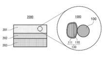
- FIG. 2 is a cross-sectional view showing a schematic configuration of the battery according to the second embodiment.
- FIG. 3 is a graph showing the X-ray diffraction pattern of the second solid electrolyte according to Examples 1, 3 and 4.
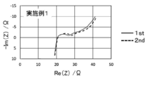
- FIG. 4A is a diagram showing a Nyquist diagram at 4.3 V of the battery in Example 1.
- FIG. 4B is a diagram showing a Nyquist diagram at 4.3 V of the battery in Example 2.
- FIG. 4C is a diagram showing a Nyquist diagram at 4.3 V of the battery in Example 3.
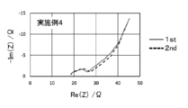
- FIG. 4D is a diagram showing a Nyquist diagram at 4.3 V of the battery in Example 4.
- FIG. 4E is a diagram showing a Nyquist diagram at 4.3 V of the battery in Comparative Example 1.
- Patent Document 1 discloses an all-solid-state lithium secondary battery using a solid electrolyte composed of a compound containing In as a cation and a halogen element such as Cl, Br, and I as an anion. It is mentioned that the battery exhibits good charge / discharge characteristics when the positive electrode active material has an average potential of 3.9 V or less with respect to Li. The reason why the battery exhibits good charge / discharge characteristics is that by setting the potential to Li of the positive electrode active material to the above value, it is possible to suppress the formation of a film composed of decomposition products due to oxidative decomposition. Has been described. Further, Patent Document 1 discloses general layered transition metal oxides such as LiCoO 2 and LiNi 0.8 Co 0.15 Al 0.05 O 2 as positive electrode active materials having an average potential to Li of 3.9 V or less. ..
- the present inventors have diligently studied the resistance of the halide solid electrolyte to oxidative decomposition. As a result, the present inventors have found that the resistance of a solid electrolyte to oxidative decomposition differs depending on the type of element contained as an anion.
- the halide solid electrolyte is a solid electrolyte containing a halogen element such as F, Cl, Br, and I as an anion.
- the present inventors when a halide solid electrolyte containing one element selected from the group consisting of Cl, Br, and I is used as the positive electrode material, the present inventors have an average anti-Li potential of 3.9 V. It has been found that the halide solid electrolyte is oxidatively decomposed during charging even when the following positive electrode active materials are used. Further, the present inventors have discovered that when the above-mentioned halide solid electrolyte is oxidatively decomposed, the product of the oxidative decomposition functions as a resistance layer, so that the internal resistance of the battery during charging increases. did.
- the increase in the internal resistance of the battery during charging is caused by the oxidation reaction of one element selected from the group consisting of Cl, Br, and I contained in the halide solid electrolyte.
- the oxidation reaction is selected from the group consisting of Cl, Br, and I, which are in contact with the positive electrode active material, in addition to the normal charging reaction in which lithium ions and electrons are extracted from the positive electrode active material in the positive electrode material. It means a side reaction in which electrons are also extracted from a halide solid electrolyte containing one element.
- the ionic radius of the halogen element is relatively large, and the interaction force between the cation component constituting the halide solid electrolyte and the halogen element is small.
- a battery using a halide solid electrolyte containing fluorine as a positive electrode material exhibits excellent oxidation resistance and can suppress an increase in the internal resistance of the battery during charging.
- the details of the mechanism are not clear, but it is presumed to be as follows.
- Fluorine has the highest electronegativity of halogen elements. When fluorine is contained in the halide solid electrolyte, the fluorine binds strongly to the cation. As a result, the oxidation reaction of fluorine, that is, the side reaction in which electrons are extracted from fluorine, is less likely to proceed.
- the present inventors have reached the positive electrode material of the present disclosure capable of suppressing an increase in the internal resistance of the battery during charging.
- the positive electrode material according to the first aspect of the present disclosure is Positive electrode active material and A coating layer containing a first solid electrolyte and covering at least a part of the surface of the positive electrode active material,
- the second solid electrolyte and Equipped with The first solid electrolyte contains Li, M1, and F.
- M1 is at least one selected from the group consisting of Ti, Al, and Zr.
- the second solid electrolyte contains Li, M2, O, and X and comprises.
- M2 is at least one selected from the group consisting of Ta and Nb.
- X is at least one selected from the group consisting of F, Cl, Br and I.
- the second solid electrolyte is 11.05 ° in an X-ray diffraction pattern obtained by X-ray diffraction measurement using Cu—K ⁇ rays.
- a crystal phase having a peak in the range of the diffraction angle 2 ⁇ of 13.86 ° or less may be included.
- the second solid electrolyte having such a structure has high lithium ion conductivity because a path for diffusion of lithium ions is easily formed.
- the molar ratio of Li to M2, Li / M2, is 0.60 or more and 2.4 or less.
- the molar ratio O / X of O to X may be 0.16 or more and 0.35 or less.
- the second solid electrolyte having such a structure a crystal phase having high lithium ion conductivity is likely to be formed. Therefore, the second solid electrolyte has higher lithium ion conductivity.
- the molar ratio of Li to M2, Li / M2, is 0.96 or more. It may be 1.20 or less. In the second solid electrolyte having such a structure, a crystal phase having high lithium ion conductivity is more likely to be formed. Therefore, the second solid electrolyte has higher lithium ion conductivity.
- M1 is at least one selected from the group consisting of Ti and Al. It may be a seed.
- the first solid electrolyte having such a structure has high lithium ion conductivity and high oxidation resistance.
- the first solid electrolyte may contain Li 2.6 Ti 0.4 Al 0.6 F 6.
- the first solid electrolyte having such a structure has higher lithium ion conductivity. Therefore, the interfacial resistance between the first solid electrolyte and the positive electrode active material can be reduced.
- M1 in the first solid electrolyte, M1 may be Zr.
- the first solid electrolyte having such a structure has high lithium ion conductivity. Therefore, the interfacial resistance between the first solid electrolyte and the positive electrode active material can be reduced.
- the first solid electrolyte may contain Li 2 ZrF 6.
- the first solid electrolyte having such a structure has higher lithium ion conductivity. Therefore, the interfacial resistance between the first solid electrolyte and the positive electrode active material can be further reduced.
- the positive electrode active material may contain lithium nickel cobalt manganate.
- the positive electrode active material having such a structure can improve the energy density and charge / discharge efficiency of the battery.
- the battery according to the tenth aspect of the present disclosure is A positive electrode containing a positive electrode material according to any one of the tenth to ninth aspects, and a positive electrode. With the negative electrode An electrolyte layer arranged between the positive electrode and the negative electrode, To prepare for.
- the electrolyte layer may contain a third solid electrolyte, and the third solid electrolyte is a solid having the same composition as the first solid electrolyte. It may be an electrolyte or a solid electrolyte having the same composition as or containing the same crystal phase as the second solid electrolyte. According to such a configuration, the output density and charge / discharge characteristics of the battery can be improved.
- the third solid electrolyte may be a solid electrolyte having the same composition as the first solid electrolyte. According to such a configuration, the output density and charge / discharge characteristics of the battery can be further improved.
- FIG. 1 is a cross-sectional view showing a schematic configuration of the positive electrode material 1000 according to the first embodiment.
- the positive electrode material 1000 in the first embodiment contains a coating active material 130 and a second solid electrolyte 100.
- the coating active material 130 includes a positive electrode active material 110 and a coating layer 111.
- the shape of the positive electrode active material 110 is, for example, a particle shape.
- the coating layer 111 covers at least a part of the surface of the positive electrode active material 110.
- the coating layer 111 is a layer containing the first solid electrolyte.
- a coating layer 111 is provided on the surface of the positive electrode active material 110.
- the coating layer 111 may contain only the first solid electrolyte. "Containing only the first solid electrolyte” means that no material other than the first solid electrolyte is intentionally added except for unavoidable impurities. For example, the raw material of the first solid electrolyte, the by-products generated when the first solid electrolyte is produced, and the like are included in the unavoidable impurities.
- the shape of the second solid electrolyte 100 is, for example, particulate. According to the second solid electrolyte 100, the ionic conductivity in the positive electrode material 1000 can be sufficiently ensured.
- the positive electrode active material 110 is separated from the second solid electrolyte 100 by the coating layer 111.
- the positive electrode active material 110 does not have to be in direct contact with the second solid electrolyte 100. This is because the coating layer 111 has ionic conductivity.
- the coating layer 111 may uniformly cover the positive electrode active material 110.
- the coating layer 111 suppresses direct contact between the positive electrode active material 110 and the second solid electrolyte 100, and suppresses a side reaction of the second solid electrolyte 100. As a result, the charge / discharge efficiency of the battery can be improved, and the increase in the reaction overvoltage of the battery can be suppressed.
- the coating layer 111 may cover only a part of the surface of the positive electrode active material 110.
- the particles of the positive electrode active material 110 come into direct contact with each other through the portion not covered by the coating layer 111, so that the electron conductivity between the particles of the positive electrode active material 110 is improved. As a result, the battery can be operated at high output.
- the thickness of the coating layer 111 may be, for example, 1 nm or more and 500 nm or less.
- the thickness of the coating layer 111 is 1 nm or more, the contact between the positive electrode active material 110 and the second solid electrolyte 100 can be suppressed, and the side reaction of the second solid electrolyte 100 can be suppressed. Therefore, the charging / discharging efficiency of the battery can be improved.
- the thickness of the coating layer 111 is 500 nm or less, the internal resistance of the battery due to the thickness of the coating layer 111 can be sufficiently reduced. Therefore, the energy density of the battery can be improved.
- the method for measuring the thickness of the coating layer 111 is not particularly limited.
- the thickness of the first solid electrolyte can be determined by direct observation using a transmission electron microscope or the like.
- XPS can be measured while scraping the coating layer 111 by Ar sputtering, and the thickness of the coating layer 111 can be obtained from the change in the spectrum derived from the active material.
- the positive electrode active material 110, the coating layer 111, and the second solid electrolyte 100 will be described in more detail.
- the first solid electrolyte contained in the coating layer 111 contains Li, M1 and F.
- M1 is at least one selected from the group consisting of Ti, Al, and Zr. That is, the first solid electrolyte is a halide solid electrolyte containing F.
- a battery using a halide solid electrolyte containing F as a positive electrode material exhibits excellent oxidation resistance, and an increase in the internal resistance of the battery during charging can be suppressed.
- the halide solid electrolyte contains F, which has a high electronegativity among halogen elements, in the anion, it binds strongly to the cation and the oxidation reaction of F, that is, the extraction of electrons from Cl. It is presumed that this is because the side reaction is difficult to proceed.
- the first solid electrolyte containing Li, M1, and F, in which M1 is at least one selected from the group consisting of Ti, Al, and Zr realizes high oxidation resistance. Therefore, when the first solid electrolyte is used as the positive electrode material, an increase in internal resistance during charging can be suppressed.
- the first solid electrolyte may substantially consist of Li, M1 and F.
- the first solid electrolyte is substantially composed of Li, M1, and F
- the substances of Li, M1, and F with respect to the total amount of substances of all the elements constituting the first solid electrolyte It means that the total molar ratio of the amounts is 90% or more. As an example, the molar ratio may be 95% or more.
- the first solid electrolyte may consist only of Li, M1 and F.
- M1 may be at least one selected from the group consisting of Ti and Al.
- the first solid electrolyte having the above structure has high lithium ion conductivity and high oxidation resistance.
- the first solid electrolyte may contain Li 2.6 Ti 0.4 Al 0.6 F 6.
- the first solid electrolyte having the above configuration exhibits higher ionic conductivity, it is possible to realize a lower interfacial resistance with the positive electrode active material.
- M1 may be Zr.
- the first solid electrolyte having the above configuration exhibits higher ionic conductivity, it is possible to realize a lower interfacial resistance with the positive electrode active material.
- the first solid electrolyte may contain Li 2 ZrF 6.
- the first solid electrolyte having the above configuration exhibits higher ionic conductivity, it is possible to realize a lower interfacial resistance with the positive electrode active material.
- the first solid electrolyte does not have to contain Y (yttrium). Further, the halide solid electrolyte does not have to contain sulfur. The first solid electrolyte does not have to contain sulfur.
- the second solid electrolyte 100 contains Li, M2, O, and X.
- M2 is at least one selected from the group consisting of Ta and Nb.
- X is at least one selected from the group consisting of F, Cl, Br and I. That is, the second solid electrolyte is a halide solid electrolyte containing at least one selected from the group consisting of Cl, Br and I.
- the second solid electrolyte may be a halide solid electrolyte containing at least one selected from the group consisting of Cl, Br and I. Further, the second solid electrolyte may contain, for example, at least one selected from the group consisting of Cl, Br and I, and F.
- the second solid electrolyte 100 has high lithium ion conductivity. Therefore, since a good interface is formed between the second solid electrolyte 100 and the first solid electrolyte, the charge transfer resistance between the second solid electrolyte 100 and the positive electrode active material can be reduced.
- the high lithium ion conductivity is, for example, 1 ⁇ 10 -3 mS / cm or more. That is, the second solid electrolyte 100 according to the first embodiment may have an ionic conductivity of, for example, 1 ⁇ 10 -3 mS / cm or more.
- the second solid electrolyte 100 may substantially consist of Li, M2, O, and X.
- the second solid electrolyte 100 is substantially composed of Li, M2, O, and X
- Li, M2 with respect to the total amount of substances of all the elements constituting the second solid electrolyte 100. It means that the molar ratio of the total amount of substances of O and X is 90% or more. As an example, the molar ratio may be 95% or more.
- the second solid electrolyte 100 may be composed of only Li, M2, O, and X.
- X may be one selected from the group consisting of Cl, Br and I.
- the second solid electrolyte 100 is a crystal phase in which a peak exists in the range of a diffraction angle of 2 ⁇ of 11.05 ° or more and 13.86 ° or less in an X-ray diffraction pattern obtained by X-ray diffraction measurement using Cu—K ⁇ rays. May include.
- the "peak” means a diffraction peak in the X-ray diffraction pattern.
- the second solid electrolyte 100 having the above configuration has high lithium ion conductivity because it easily forms a path for diffusion of lithium ions.
- the X-ray diffraction pattern of the solid electrolyte according to the first embodiment uses Cu—K ⁇ rays (wavelengths 1.5405 ⁇ and 1.5444 ⁇ , that is, wavelengths 0.15455 nm and 0.15444 nm), and X-rays by the ⁇ -2 ⁇ method. Can be obtained by diffraction measurement.
- the second solid electrolyte 100 may further contain another crystal phase different from the crystal phase in which the peak exists in the range of the diffraction angle 2 ⁇ . That is, the second solid electrolyte 100 further comprises another crystal phase having a peak in the range of the diffraction angle 2 ⁇ different from the peak of the crystal phase having the peak in the range of the diffraction angle 2 ⁇ in the X-ray diffraction pattern. It may be included. Another crystal phase may be interposed between the crystal phases having a peak in the range of the diffraction angle 2 ⁇ .
- the molar ratio Li / M2 of Li to M2 may be 0.60 or more and 2.4 or less.
- the molar ratio O / X of O to X may be 0.16 or more and 0.35 or less.
- the second solid electrolyte 100 having the above configuration can realize higher lithium ion conductivity. Specifically, when the molar ratio Li / M2 is in the above range, the concentration of Li as a conduction carrier can be optimized. When the molar ratio O / X is in the above range, a crystal phase having high ionic conductivity is likely to be realized. Therefore, the lithium ion conductivity is further improved.
- the molar ratio of Li to M2, Li / M2, may be 0.96 or more and 1.20 or less.
- the second solid electrolyte 100 having the above configuration has higher lithium ion conductivity because a crystal phase having high ionic conductivity is more easily realized.
- the second solid electrolyte 100 does not have to contain Y (yttrium). Further, the second solid electrolyte does not have to contain sulfur.
- the positive electrode active material 110 includes a material having the property of occluding and releasing metal ions (for example, lithium ions).
- a lithium-containing transition metal oxide, a transition metal fluoride, a polyanionic material, a fluorinated polyanionic material, a transition metal sulfide, a transition metal oxysulfide, a transition metal oxynitride, and the like can be used. ..
- Examples of lithium-containing transition metal oxides include Li (NiCoAl) O 2 , Li (NiCoMn) O 2 , LiCoO 2 , and the like.
- the manufacturing cost can be reduced and the average discharge voltage can be increased.
- the positive electrode active material 110 may contain Ni, Co, and Mn.
- the positive electrode active material 110 may contain lithium nickel cobalt manganate.
- the positive electrode active material 110 may contain Li (NiComn) O 2.
- the energy density and charge / discharge efficiency of the battery can be further increased.
- the shape of the second solid electrolyte 100 is not particularly limited.
- its shape may be, for example, needle-shaped, spherical, elliptical spherical, or the like.
- the shape of the second solid electrolyte 100 may be particulate.
- the median diameter when the shape of the second solid electrolyte 100 is particulate (for example, spherical), the median diameter may be 100 ⁇ m or less. When the median diameter is 100 ⁇ m or less, the coating active material 130 and the second solid electrolyte 100 can form a good dispersed state in the positive electrode material 1000. Therefore, the charge / discharge characteristics of the battery are improved. In the first embodiment, the median diameter of the second solid electrolyte 100 may be 10 ⁇ m or less.
- the coating active material 130 and the second solid electrolyte 100 can form a good dispersed state.
- the median diameter of the second solid electrolyte 100 may be smaller than the median diameter of the coating active material 130.
- the second solid electrolyte 100 and the coating active material 130 can form a better dispersed state in the positive electrode material 1000.
- the median diameter of the coating active material 130 may be 0.1 ⁇ m or more and 100 ⁇ m or less.
- the coating active material 130 and the second solid electrolyte 100 can form a good dispersed state in the positive electrode material 1000. As a result, the charge / discharge characteristics of the battery are improved.
- the battery can operate at high output.
- the median diameter of the coating active material 130 may be larger than the median diameter of the second solid electrolyte 100. As a result, the coating active material 130 and the second solid electrolyte 100 can form a good dispersed state.
- the median diameter means the particle size when the cumulative volume in the volume-based particle size distribution is equal to 50%.
- the volume-based particle size distribution is measured, for example, by a laser diffraction measuring device or an image analysis device.
- At least a part of the surface of the coating layer 111 may be covered with a different coating material.
- Different coating materials include Li-Nb-O compounds such as LiNbO 3 , Li-BO compounds such as LiBO 2 and Li 3 BO 3 , Li-Al-O compounds such as LiAlO 2, and Li such as Li 4 SiO 4.
- -Si-O compounds Li -Ti-O compounds such as Li 2 SO 4 , Li 4 Ti 5 O 12 , Li-Zr-O compounds such as Li 2 ZrO 3, and Li-Mo-O such as Li 2 MoO 3. It may contain a compound, a Li—V—O compound such as LiV 2 O 5 , a Li—W—O compound such as Li 2 WO 4 , or a Li—PO compound such as Li 3 PO 4 .
- the second solid electrolyte 100 and the coating active material 130 may be in contact with each other as shown in FIG. At this time, the coating layer 111 and the positive electrode active material 110 are in contact with each other.
- It may contain a plurality of particles of the second solid electrolyte 100 and a plurality of particles of the coating active material 130.
- the content of the second solid electrolyte 100 and the content of the coating active material 130 may be the same or different from each other.
- the first solid electrolyte and the second solid electrolyte 100 contained in the coating layer 111 can be produced, for example, by the following methods.
- a raw material powder of a binary halide having a blending ratio of a desired composition is prepared and mixed.
- LiF, TiF 4 and AlF 3 are prepared in a molar ratio of about 2.6: 0.4: 0.6.
- the compounding ratio may be adjusted in advance so as to offset the change in the composition in consideration of the change in the composition in the process of the synthesis process.
- the raw material powder may be fired in a vacuum or in an inert atmosphere.
- the firing conditions for example, it is preferable to perform firing for 1 hour or more in the range of 100 ° C to 300 ° C.
- a closed container such as a quartz tube and perform firing.
- the first solid electrolyte and the second solid electrolyte 100 can be obtained.
- composition of the solid electrolyte can be determined, for example, by ICP emission spectroscopy or ion chromatography.
- the position of the X-ray diffraction peak in the solid electrolyte, that is, the composition of the crystal phase can be adjusted to the desired one by selecting the raw material powder, setting the mixing ratio of the raw material powder, adjusting the reaction method and reaction conditions of the raw material powder.
- the coating active material 130 can be produced, for example, by the following method.
- a powder of the positive electrode active material 110 and a powder of the first solid electrolyte are prepared at a predetermined mass ratio.
- Li (NiComn) O 2 powder is prepared as the positive electrode active material 110
- Li 2.7 Ti 0.3 Al 0.7 F 6 powder is prepared as the first solid electrolyte.
- the mixture may be milled before mechanical energy is applied to the mixture of the powder of the positive electrode active material 110 and the powder of the first solid electrolyte.
- a mixing device such as a ball mill can be used for the milling process.
- the milling treatment may be carried out in a dry atmosphere and an inert atmosphere.
- the coating active material 130 may be produced by a dry particle composite method.
- Treatment by the dry particle composite method comprises applying at least one mechanical energy selected from the group consisting of impact, compression and shear to the positive electrode active material 110 and the first solid electrolyte.
- the positive electrode active material 110 and the first solid electrolyte are mixed in an appropriate ratio.
- the apparatus used in the method for producing the coating active material 130 is not particularly limited, and may be an apparatus capable of imparting mechanical energy such as impact, compression, and shear to the mixture of the positive electrode active material 110 and the first solid electrolyte. ..
- compression shear type processing devices particle compounding devices
- mechanical energy such as ball mills, jet mills, "Mechanofusion” (manufactured by Hosokawa Micron), “Nobilta” (manufactured by Hosokawa Micron), and “hybridization systems” (High-speed airflow impact device) ”(manufactured by Nara Machinery Co., Ltd.) and the like.
- Mechanism is a particle compounding device that uses dry mechanical compounding technology by applying strong mechanical energy to multiple different material particles.
- mechanofusion the powder raw material charged between the rotating container and the press head is subjected to mechanical energy such as compression, shearing, and friction, so that the particles are compounded.
- Novirta is a particle compositing device that uses dry mechanical compositing technology, which is a development of particle compositing technology, in order to composite nanoparticles using nanoparticles as a raw material. Novirta produces composite particles by applying impact, compression, and shear mechanical energies to multiple feedstock powders.
- a rotor in a horizontal cylindrical mixing container, a rotor arranged so as to have a predetermined gap with the inner wall of the mixing container rotates at high speed and forcibly passes through the gap with respect to the raw material powder. The process of causing is repeated multiple times. This makes it possible to apply impact, compression, and shear forces to the mixture to produce composite particles of the positive electrode active material 110 and the first solid electrolyte. Conditions such as rotor rotation speed, processing time, and charging amount can be adjusted as appropriate.
- the raw material powder is dispersed in the high-speed air flow, and the force mainly due to the impact is applied. As a result, composite particles of the positive electrode active material 110 and the first solid electrolyte are produced.
- the positive electrode material 1000 is obtained.
- the method of mixing the coating active material 130 and the second solid electrolyte 100 is not particularly limited.
- the coating active material 130 and the second solid electrolyte 100 may be mixed using an instrument such as a dairy bowl, or the coating active material 130 and the second solid electrolyte 100 may be mixed using a mixing device such as a ball mill. May be good.
- the mixing ratio of the coating active material 130 and the second solid electrolyte 100 is not particularly limited.
- FIG. 2 is a cross-sectional view showing a schematic configuration of the battery 2000 according to the second embodiment.
- the battery 2000 in the second embodiment includes a positive electrode 201, an electrolyte layer 202, and a negative electrode 203.
- the positive electrode 201 includes the positive electrode material 1000 according to the first embodiment.
- the electrolyte layer 202 is arranged between the positive electrode 201 and the negative electrode 203.
- v1 represents the volume ratio of the positive electrode material 1000 when the total volume of the positive electrode material 1000 and the second solid electrolyte 100 contained in the positive electrode 201 is 100.
- v1 represents the volume ratio of the positive electrode material 1000 when the total volume of the positive electrode material 1000 and the second solid electrolyte 100 contained in the positive electrode 201 is 100.
- the thickness of the positive electrode 201 may be 10 ⁇ m or more and 500 ⁇ m or less. When the thickness of the positive electrode 201 is 10 ⁇ m or more, the energy density of the battery 2000 is sufficiently secured. When the thickness of the positive electrode 201 is 500 ⁇ m or less, operation at high output is possible.
- the electrolyte layer 202 is a layer containing an electrolyte.
- the electrolyte is, for example, a solid electrolyte.
- the solid electrolyte contained in the electrolyte layer 202 is called a third solid electrolyte. That is, the electrolyte layer 202 may contain a third solid electrolyte.
- the third solid electrolyte may be a halide solid electrolyte.
- a solid electrolyte having the same composition as the first solid electrolyte in the first embodiment, or a solid electrolyte having the same composition as the second solid electrolyte or containing the same crystal phase may be used. That is, the electrolyte layer 202 may contain a solid electrolyte having the same composition as the first solid electrolyte in the first embodiment, or a solid electrolyte having the same composition as the second solid electrolyte or containing the same crystal phase.
- the third solid electrolyte may be a solid electrolyte having the same composition as the first solid electrolyte in the first embodiment. That is, the electrolyte layer 202 may contain a solid electrolyte having the same composition as the first solid electrolyte in the first embodiment.
- the output density and charge / discharge characteristics of the battery can be further improved.
- the third solid electrolyte may be a halide solid electrolyte having a composition different from that of the first solid electrolyte, and the halide solid electrolyte having a composition different from that of the second solid electrolyte or containing a different crystal phase.
- the electrolyte layer 202 may contain a halide solid electrolyte having a composition different from that of the first solid electrolyte, and the halide solid electrolyte having a composition different from that of the second solid electrolyte or containing a different crystal phase. May include.
- the third solid electrolyte may be a sulfide solid electrolyte, an oxide solid electrolyte, a polymer solid electrolyte, or a complex hydride solid electrolyte.
- the solid electrolyte is a sulfide solid electrolyte
- the sulfide solid electrolyte Li 2 S-P 2 S 5, Li 2 S-SiS 2, Li 2 S-B 2 S 3, Li 2 S-GeS 2 , Li 3.25 Ge 0.25 P 0.75 S 4 , Li 10 GeP 2 S 12 and the like
- LiX, Li 2 O, MO q, like Li p MO q may be added.
- the element X in "LiX" is at least one element selected from the group consisting of F, Cl, Br, and I.
- the element M in "MO q " and “Li p MO q” is at least one element selected from the group consisting of P, Si, Ge, B, Al, Ga, In, Fe, and Zn.
- P and q in “MO q “ and “Li p MO q " are independent natural numbers, respectively.
- the electrolyte layer 202 contains a sulfide solid electrolyte having excellent reduction stability, a low-potential negative electrode material such as graphite or metallic lithium can be used, and the energy density of the battery 2000 can be improved. Can be done.
- the oxide solid electrolyte may be, for example, a NASION type solid electrolyte represented by LiTi 2 (PO 4 ) 3 and an elemental substituent thereof, or a (LaLi) TiO 3 system.
- Perovskite type solid electrolytes, Li 14 ZnGe 4 O 16 , Li 4 SiO 4 , LiGeO 4 and LISION type solid electrolytes typified by elemental substituents, Li 7 La 3 Zr 2 O 12 and their elemental substituents are typified.
- Li 3 N and its H-substituted product Li 3 PO 4 and its N-substituted product, and Li-BO compounds such as Li BO 2 and Li 3 BO 3 , Li 2 SO 4 , Glass or glass ceramics to which a material such as Li 2 CO 3 is added can be used.
- the third solid electrolyte is a polymer solid electrolyte
- a compound of a polymer compound and a lithium salt can be used as the polymer solid electrolyte.
- the polymer compound may have an ethylene oxide structure. By having an ethylene oxide structure, the polymer compound can contain a large amount of lithium salt. Therefore, the ionic conductivity can be further increased.
- the lithium salt LiPF 6, LiBF 4, LiSbF 6, LiAsF 6, LiSO 3 CF 3, LiN (SO 2 CF 3) 2, LiN (SO 2 C 2 F 5) 2, LiN (SO 2 CF 3) ( SO 2 C 4 F 9 ), LiC (SO 2 CF 3 ) 3 , etc. may be used.
- the lithium salt one kind of lithium salt selected from these may be used alone, or a mixture of two or more kinds of lithium salts selected from these may be used.
- the third solid electrolyte is a complex hydride solid electrolyte
- LiBH 4- LiI, LiBH 4- P 2 S 5 and the like can be used as the complex hydride solid electrolyte.
- the electrolyte layer 202 may contain a third solid electrolyte as a main component. That is, the electrolyte layer 202 may contain, for example, 50% or more (that is, 50% by mass or more) of the third solid electrolyte in terms of mass ratio with respect to the entire electrolyte layer 202.
- the charge / discharge characteristics of the battery 2000 can be further improved.
- the electrolyte layer 202 may contain 70% or more (that is, 70% by mass or more) of the third solid electrolyte in terms of mass ratio with respect to the entire electrolyte layer 202.
- the charge / discharge characteristics of the battery 2000 can be further improved.
- the electrolyte layer 202 contains the third solid electrolyte as a main component, and further contains unavoidable impurities, starting materials, by-products, decomposition products and the like used in synthesizing the third solid electrolyte. You may.
- the electrolyte layer 202 may contain 100% (that is, 100% by mass) of the third solid electrolyte in terms of mass ratio to the whole of the electrolyte layer 202, for example, excluding impurities inevitably mixed.
- the charge / discharge characteristics of the battery 2000 can be further improved.
- the electrolyte layer 202 may be composed of only the third solid electrolyte.
- the electrolyte layer 202 may contain two or more of the materials listed as the third solid electrolyte.
- the electrolyte layer 202 may contain a halide solid electrolyte and a sulfide solid electrolyte.
- the thickness of the electrolyte layer 202 may be 1 ⁇ m or more and 300 ⁇ m or less. When the thickness of the electrolyte layer 202 is 1 ⁇ m or more, the positive electrode 201 and the negative electrode 203 are less likely to be short-circuited. When the thickness of the electrolyte layer 202 is 300 ⁇ m or less, the battery 2000 can operate at high output.
- the negative electrode 203 contains a material having the property of occluding and releasing metal ions (for example, lithium ions).
- the negative electrode 203 contains, for example, a negative electrode active material.
- a metal material, a carbon material, an oxide, a nitride, a tin compound, a silicon compound, or the like can be used.
- the metal material may be a single metal.
- the metal material may be an alloy.
- metal materials include lithium metal and lithium alloys.
- Examples of carbon materials include natural graphite, coke, developing carbon, carbon fibers, spheroidal carbon, artificial graphite, amorphous carbon and the like. From the viewpoint of capacitance density, silicon (Si), tin (Sn), silicon compounds, and tin compounds can be used.
- the negative electrode 203 may contain a solid electrolyte.
- the solid electrolyte the solid electrolyte exemplified as the material constituting the electrolyte layer 202 may be used. According to the above configuration, the lithium ion conductivity inside the negative electrode 203 is enhanced, and the battery 2000 can be operated at a high output.
- the median diameter of the particles of the negative electrode active material may be 0.1 ⁇ m or more and 100 ⁇ m or less.
- the median diameter of the particles of the negative electrode active material is 0.1 ⁇ m or more, the negative electrode active material and the solid electrolyte can form a good dispersed state in the negative electrode. This improves the charge / discharge characteristics of the battery 2000.
- the median diameter of the particles of the negative electrode active material is 100 ⁇ m or less, the lithium diffusion in the negative electrode active material becomes fast. Therefore, the battery 2000 can operate at high output.
- the median diameter of the particles of the negative electrode active material may be larger than the median diameter of the particles of the solid electrolyte contained in the negative electrode 203. This makes it possible to form a good dispersed state between the particles of the negative electrode active material and the particles of the solid electrolyte.
- v2 represents the volume ratio of the negative electrode active material particles contained in the negative electrode 203 when the total volume of the negative electrode active material particles and the solid electrolyte is 100.
- a sufficient energy density of the battery 2000 can be secured.
- the battery 2000 can operate at high output.
- the thickness of the negative electrode 203 may be 10 ⁇ m or more and 500 ⁇ m or less. When the thickness of the negative electrode 203 is 10 ⁇ m or more, sufficient energy density of the battery 2000 can be secured. When the thickness of the negative electrode 203 is 500 ⁇ m or less, the battery 2000 can operate at a high output.
- At least one of the positive electrode 201, the electrolyte layer 202, and the negative electrode 203 may contain a binder for the purpose of improving the adhesion between the particles.
- the binder is used to improve the binding property of the material constituting the electrode. Binders include polyvinylidene fluoride, polytetrafluoroethylene, polyethylene, polypropylene, aramid resin, polyamide, polyimide, polyamideimide, polyacrylic nitrile, polyacrylic acid, polyacrylic acid methyl ester, polyacrylic acid ethyl ester, and poly.
- Polyacrylic acid hexyl ester polymethacrylic acid, polymethacrylic acid methyl ester, polymethacrylic acid ethyl ester, polymethacrylic acid hexyl ester, polyvinyl acetate, polyvinylpyrrolidone, polyether, polyether sulfone, hexafluoropolypropylene, styrene butadiene rubber, And carboxymethyl cellulose, and the like.
- the binders include tetrafluoroethylene, hexafluoroethylene, hexafluoropropylene, perfluoroalkyl vinyl ether, vinylidene fluoride, chlorotrifluoroethylene, ethylene, propylene, pentafluoropropylene, fluoromethyl vinyl ether, acrylic acid, and acrylic acid.
- Copolymers of two or more materials selected from the group consisting of hexadiene can be used. Further, a mixture of two or more kinds selected from these may be used.
- At least one of the positive electrode 201 and the negative electrode 203 may contain a conductive auxiliary agent for the purpose of enhancing electronic conductivity.
- the conductive auxiliary agent include graphites of natural graphite and artificial graphite, carbon blacks such as acetylene black and Ketjen black, conductive fibers such as carbon fibers and metal fibers, and metal powders such as carbon fluoride and aluminum. Classes, conductive whiskers such as zinc oxide and potassium titanate, conductive metal oxides such as titanium oxide, and conductive polymer compounds such as polyaniline, polypyrrole, and polythiophene can be used.
- a carbon conductive auxiliary agent is used as the conductive auxiliary agent, the cost can be reduced.
- the battery in the second embodiment can be configured as a battery having various shapes such as a coin type, a cylindrical type, a square type, a sheet type, a button type, a flat type, and a laminated type.
- Example 1 [Preparation of the first solid electrolyte]
- the composition of the first solid electrolyte according to Example 1 is shown in Table 1.
- the X-ray diffraction pattern of the second solid electrolyte according to Example 1 was measured by the ⁇ -2 ⁇ method using an X-ray diffractometer (Rigaku, MiniFlex600) in a dry environment having a dew point of ⁇ 50 ° C. or lower.
- Cu-K ⁇ rays (wavelengths 1.5405 ⁇ and 1.5444 ⁇ ) were used as the X-ray source.
- FIG. 3 is a graph showing the X-ray diffraction pattern of the second solid electrolyte according to Example 1.
- the crystal phase contained in the second solid electrolyte according to Example 1 is 11.05 ° or more in the X-ray diffraction pattern obtained by the X-ray diffraction measurement using Cu—K ⁇ ray. It had a peak in the range of the diffraction angle 2 ⁇ of 86 ° or less.
- the molar ratio of Li to Ta, Li / Ta was 1.0 (charge ratio).
- Example 2 [Preparation of the first solid electrolyte]
- the mixture obtained under the conditions of 500 rpm for 12 hours was milled.
- the powder of the first solid electrolyte according to Example 2 represented by the composition formula of Li 2 ZrF 6 was obtained.
- the composition of the first solid electrolyte according to Example 2 is shown in Table 1.
- the X-ray diffraction pattern of the second solid electrolyte according to Example 2 was measured in the same manner as in Example 1.
- the crystal phase contained in the second solid electrolyte according to Example 2 has a diffraction angle of 2 ⁇ of 11.05 ° or more and 13.86 ° or less in the X-ray diffraction pattern obtained by X-ray diffraction measurement using Cu—K ⁇ rays. It had a peak in the range.
- the molar ratio of Li to Ta, Li / Ta was 1.0 (charge ratio).
- Example 3 [Preparation of the first solid electrolyte]
- the composition of the first solid electrolyte according to Example 3 is shown in Table 1.
- the X-ray diffraction pattern of the second solid electrolyte according to Example 3 was measured in the same manner as in Example 1. As shown in FIG. 3, the crystal phase contained in the second solid electrolyte according to Example 3 is 11.05 ° or more in the X-ray diffraction pattern obtained by the X-ray diffraction measurement using Cu—K ⁇ ray. It had a peak in the range of the diffraction angle 2 ⁇ of 86 ° or less.
- the molar ratio of Li to Nb, Li / Nb, was 1.0 (charge ratio).
- the molar ratio of O to Cl, O / Cl, was 0.2 (preparation ratio).
- Example 4 [Preparation of the first solid electrolyte]
- the composition of the first solid electrolyte according to Example 4 is shown in Table 1.
- the X-ray diffraction pattern of the second solid electrolyte according to Example 4 was measured in the same manner as in Example 1. As shown in FIG. 3, the crystal phase contained in the second solid electrolyte contained in Example 4 is 11.05 ° or more in the X-ray diffraction pattern obtained by the X-ray diffraction measurement using Cu—K ⁇ ray. It had a peak in the range of the diffraction angle 2 ⁇ of 13.86 ° or less.
- Comparative Example 1 [Preparation of positive electrode material]
- the positive electrode active material NCM and the second solid electrolyte of Example 1 were weighed so as to have a mass ratio of 77.09: 22.91. By mixing these materials in a mortar, a positive electrode material according to Comparative Example 1 was prepared.
- Example 1 The positive electrode material of Example 1 from 4, and Comparative Example 1 described above, the sulfide solid electrolyte glass ceramics like Li 2 S-P 2 S 5 (hereinafter, referred to as LPS) and, halide solid electrolyte The following steps were carried out using a certain Li 3 Y 1 Br 2 Cl 4 (hereinafter referred to as LYBC).
- LPS Li 2 S-P 2 S 5
- LYBC Li 3 Y 1 Br 2 Cl 4
- LPS equivalent to 550 ⁇ m thickness (equivalent to 80 mg), LYBC equivalent to 50 ⁇ m thickness (equivalent to 20 mg), and positive electrode materials were laminated in this order.
- the mass of the positive electrode material was adjusted so that the mass of the positive electrode active material contained therein was 8.2 mg.
- the mass of the positive electrode material of Example 1 was 10.47 mg.
- the mass of the positive electrode material of Example 2 was 10.91 mg.
- the mass of the positive electrode material of Example 3 was 10.08 mg.
- the mass of the positive electrode material of Example 4 was 10.21 mg.
- the mass of the positive electrode material of Comparative Example 1 was 10.32.
- Each laminate was pressure-molded at a pressure of 360 MPa to obtain a positive electrode and a solid electrolyte layer.
- a metal Li having a thickness of 200 ⁇ m was laminated on the solid electrolyte layer on the side opposite to the side in contact with the positive electrode.
- the obtained laminate was pressure-molded at a pressure of 80 MPa to prepare a laminate composed of a positive electrode, a solid electrolyte layer, and a negative electrode.
- the battery was placed in a constant temperature bath at 25 ° C.
- the battery was charged with a constant current at a rate of 0.05 C (20 hours rate) with respect to the theoretical capacity of the battery.
- the charge termination voltage was set to 4.3 V (vs. Li).
- FIGS. 4A to 4E are diagrams showing Nyquist diagrams at 4.3 V of the batteries in Examples 1 to 4 and Comparative Example 1, respectively.
- the horizontal axis and the vertical axis of FIGS. 4A to 4E represent the real part of the impedance and the imaginary part of the impedance, respectively.
- the battery was discharged at a current value of 0.05 C rate.
- the discharge cutoff voltage was 2.5 V (vs. Li).
- the charging / discharging at the above 0.05C rate was repeated twice, and the increase ratio of the interface resistance value with the positive electrode after charging was calculated.
- Table 1 shows the increase ratio of the interface resistance value with the positive electrode in each of Examples 1 to 4 and Comparative Example 1.
- the battery of the present disclosure can be used, for example, as an all-solid-state lithium-ion secondary battery.
- Positive electrode material 100 Second solid electrolyte 110 Positive electrode active material 111 Coating layer 130 Coating active material 2000 Battery 201 Positive electrode 202 Electrolyte layer 203 Negative electrode
Abstract
A positive electrode material 1000 in one embodiment of the present disclosure comprises a positive electrode active material 110, a coating layer 111 that includes a first solid electrolyte and covers at least part of the surface of the positive electrode active material 110, and a second solid electrolyte 100. The first solid electrolyte contains Li, M1, and F. M1 is at least one selected from the group consisting of Ti, Al, and Zr. The second solid electrolyte 100 contains Li, M2, O, and X. M2 is at least one selected from the group consisting of Ta and Nb. X is at least one selected from the group consisting of F, Cl, Br, and I.
Description
本開示は、電池用の正極材料および電池に関する。
This disclosure relates to a positive electrode material for a battery and a battery.
特許文献1には、Inをカチオンとして含み、Cl、Br、I等のハロゲン元素をアニオンとして含む固体電解質を用いた電池が開示されている。
Patent Document 1 discloses a battery using a solid electrolyte containing In as a cation and a halogen element such as Cl, Br, I as an anion.
従来技術においては、充電時における電池の内部抵抗の上昇を抑制することが望まれる。
In the prior art, it is desired to suppress an increase in the internal resistance of the battery during charging.
本開示の一様態における正極材料は、
正極活物質と、
第1固体電解質を含み、前記正極活物質の表面の少なくとも一部を被覆する被覆層と、
第2固体電解質と、
を備え、
前記第1固体電解質は、Li、M1、およびFを含み、
M1は、Ti、Al、およびZrからなる群より選択される少なくとも1種であり、
前記第2固体電解質は、Li、M2、O、およびXを含み、
M2は、TaおよびNbからなる群より選択される少なくとも1種であり、
Xは、F、Cl、BrおよびIからなる群より選択される少なくとも1種である。 The positive electrode material in the uniform state of the present disclosure is
Positive electrode active material and
A coating layer containing a first solid electrolyte and covering at least a part of the surface of the positive electrode active material,
The second solid electrolyte and
Equipped with
The first solid electrolyte contains Li, M1, and F.
M1 is at least one selected from the group consisting of Ti, Al, and Zr.
The second solid electrolyte contains Li, M2, O, and X and comprises.
M2 is at least one selected from the group consisting of Ta and Nb.
X is at least one selected from the group consisting of F, Cl, Br and I.
本開示によれば、充電時における電池の内部抵抗の上昇を抑制することができる。
According to the present disclosure, it is possible to suppress an increase in the internal resistance of the battery during charging.
(本開示の基礎となった知見)
特許文献1には、Inをカチオンとして含み、Cl、Br、I等のハロゲン元素をアニオンとして含む化合物からなる固体電解質を用いた全固体型リチウム二次電池が開示されている。当該電池は、正極活物質の対Li電位が平均で3.9V以下であることにより、良好な充放電特性を示すと言及されている。当該電池が良好な充放電特性を示すのは、正極活物質の対Li電位を上記の値とすることにより、酸化分解による分解生成物からなる皮膜の形成を抑制することができるためであると記載されている。また、特許文献1には、対Li電位が平均で3.9V以下の正極活物質として、LiCoO2、LiNi0.8Co0.15Al0.05O2等の一般的な層状遷移金属酸化物が開示されている。 (Findings underlying this disclosure)
Patent Document 1 discloses an all-solid-state lithium secondary battery using a solid electrolyte composed of a compound containing In as a cation and a halogen element such as Cl, Br, and I as an anion. It is mentioned that the battery exhibits good charge / discharge characteristics when the positive electrode active material has an average potential of 3.9 V or less with respect to Li. The reason why the battery exhibits good charge / discharge characteristics is that by setting the potential to Li of the positive electrode active material to the above value, it is possible to suppress the formation of a film composed of decomposition products due to oxidative decomposition. Has been described. Further, Patent Document 1 discloses general layered transition metal oxides such as LiCoO 2 and LiNi 0.8 Co 0.15 Al 0.05 O 2 as positive electrode active materials having an average potential to Li of 3.9 V or less. ..
特許文献1には、Inをカチオンとして含み、Cl、Br、I等のハロゲン元素をアニオンとして含む化合物からなる固体電解質を用いた全固体型リチウム二次電池が開示されている。当該電池は、正極活物質の対Li電位が平均で3.9V以下であることにより、良好な充放電特性を示すと言及されている。当該電池が良好な充放電特性を示すのは、正極活物質の対Li電位を上記の値とすることにより、酸化分解による分解生成物からなる皮膜の形成を抑制することができるためであると記載されている。また、特許文献1には、対Li電位が平均で3.9V以下の正極活物質として、LiCoO2、LiNi0.8Co0.15Al0.05O2等の一般的な層状遷移金属酸化物が開示されている。 (Findings underlying this disclosure)
一方、本発明者らは、ハロゲン化物固体電解質の酸化分解に対する耐性について鋭意検討した。その結果、本発明者らは、アニオンとして含まれる元素の種類によって、固体電解質の酸化分解に対する耐性が異なることを見出した。ここで、ハロゲン化物固体電解質とは、F、Cl、Br、Iなどのハロゲン元素をアニオンとして含む固体電解質である。
On the other hand, the present inventors have diligently studied the resistance of the halide solid electrolyte to oxidative decomposition. As a result, the present inventors have found that the resistance of a solid electrolyte to oxidative decomposition differs depending on the type of element contained as an anion. Here, the halide solid electrolyte is a solid electrolyte containing a halogen element such as F, Cl, Br, and I as an anion.
具体的には、本発明者らは、Cl、Br、およびIからなる群より選択される1種の元素を含むハロゲン化物固体電解質を正極材料に使用すると、対Li電位が平均で3.9V以下の正極活物質を用いた場合であっても、充電中にハロゲン化物固体電解質が酸化分解することを見出した。また、本発明者らは、上述のようなハロゲン化物固体電解質が酸化分解した場合、酸化分解による生成物が抵抗層として機能することにより、充電時における電池の内部抵抗が上昇するという課題を発見した。この充電時における電池の内部抵抗の上昇は、ハロゲン化物固体電解質に含まれるCl、Br、およびIからなる群より選択される1種の元素の酸化反応が原因であると推察される。ここで、酸化反応とは、正極材料中の正極活物質からリチウムイオンと電子が引き抜かれる通常の充電反応に加えて、正極活物質と接する、Cl、Br、およびIからなる群より選択される1種の元素を含むハロゲン化物固体電解質からも電子が引き抜かれる副反応を意味する。ハロゲン元素のイオン半径は比較的大きく、ハロゲン化物固体電解質を構成するカチオン成分とハロゲン元素との相互作用力が小さい。そのため、ハロゲン化物固体電解質の酸化反応が起こりやすいと考えられる。この酸化反応に伴い、正極活物質とハロゲン化物固体電解質との間に、リチウムイオンの伝導性に乏しい酸化分解層が形成される。この酸化分解層が、正極の電極反応において大きな界面抵抗として機能する。これにより、充電時に電池の内部抵抗が上昇すると考えられる。
Specifically, when a halide solid electrolyte containing one element selected from the group consisting of Cl, Br, and I is used as the positive electrode material, the present inventors have an average anti-Li potential of 3.9 V. It has been found that the halide solid electrolyte is oxidatively decomposed during charging even when the following positive electrode active materials are used. Further, the present inventors have discovered that when the above-mentioned halide solid electrolyte is oxidatively decomposed, the product of the oxidative decomposition functions as a resistance layer, so that the internal resistance of the battery during charging increases. did. It is presumed that the increase in the internal resistance of the battery during charging is caused by the oxidation reaction of one element selected from the group consisting of Cl, Br, and I contained in the halide solid electrolyte. Here, the oxidation reaction is selected from the group consisting of Cl, Br, and I, which are in contact with the positive electrode active material, in addition to the normal charging reaction in which lithium ions and electrons are extracted from the positive electrode active material in the positive electrode material. It means a side reaction in which electrons are also extracted from a halide solid electrolyte containing one element. The ionic radius of the halogen element is relatively large, and the interaction force between the cation component constituting the halide solid electrolyte and the halogen element is small. Therefore, it is considered that the oxidation reaction of the halide solid electrolyte is likely to occur. Along with this oxidation reaction, an oxidative decomposition layer having poor lithium ion conductivity is formed between the positive electrode active material and the halide solid electrolyte. This oxidative decomposition layer functions as a large interfacial resistance in the electrode reaction of the positive electrode. As a result, it is considered that the internal resistance of the battery increases during charging.
また、本発明者らは、フッ素を含むハロゲン化物固体電解質を正極材料に用いた電池は、優れた酸化耐性を示し、充電時における電池の内部抵抗の上昇を抑制できることを明らかにした。そのメカニズムの詳細は明らかではないが、以下の通りと推察される。フッ素は、ハロゲン元素の中で最も大きい電気陰性度を有する。フッ素がハロゲン化物固体電解質に含まれている場合、フッ素がカチオンと強く結合する。その結果、フッ素の酸化反応、すなわちフッ素から電子が引き抜かれる副反応が進行しにくくなる。
Further, the present inventors have clarified that a battery using a halide solid electrolyte containing fluorine as a positive electrode material exhibits excellent oxidation resistance and can suppress an increase in the internal resistance of the battery during charging. The details of the mechanism are not clear, but it is presumed to be as follows. Fluorine has the highest electronegativity of halogen elements. When fluorine is contained in the halide solid electrolyte, the fluorine binds strongly to the cation. As a result, the oxidation reaction of fluorine, that is, the side reaction in which electrons are extracted from fluorine, is less likely to proceed.
以上の知見により、本発明者らは、充電時における電池の内部抵抗の上昇を抑制することが可能な、本開示の正極材料に到達した。
Based on the above findings, the present inventors have reached the positive electrode material of the present disclosure capable of suppressing an increase in the internal resistance of the battery during charging.
(本開示に係る一態様の概要)
本開示の第1態様に係る正極材料は、
正極活物質と、
第1固体電解質を含み、前記正極活物質の表面の少なくとも一部を被覆する被覆層と、
第2固体電解質と、
を備え、
前記第1固体電解質は、Li、M1、およびFを含み、
M1は、Ti、Al、およびZrからなる群より選択される少なくとも1種であり、
前記第2固体電解質は、Li、M2、O、およびXを含み、
M2は、TaおよびNbからなる群より選択される少なくとも1種であり、
Xは、F、Cl、BrおよびIからなる群より選択される少なくとも1種である。 (Summary of one aspect pertaining to this disclosure)
The positive electrode material according to the first aspect of the present disclosure is
Positive electrode active material and
A coating layer containing a first solid electrolyte and covering at least a part of the surface of the positive electrode active material,
The second solid electrolyte and
Equipped with
The first solid electrolyte contains Li, M1, and F.
M1 is at least one selected from the group consisting of Ti, Al, and Zr.
The second solid electrolyte contains Li, M2, O, and X and comprises.
M2 is at least one selected from the group consisting of Ta and Nb.
X is at least one selected from the group consisting of F, Cl, Br and I.
以上の構成によれば、充電時における電池の内部抵抗の上昇を抑制することができる。
According to the above configuration, it is possible to suppress an increase in the internal resistance of the battery during charging.
本開示の第2態様において、例えば、第1態様に係る正極材料では、前記第2固体電解質は、Cu-Kα線を用いたX線回折測定によって得られるX線回折パターンにおいて、11.05°以上13.86°以下の回折角2θの範囲にピークが存在する結晶相を含んでもよい。このような構成を有する第2固体電解質は、リチウムイオンが拡散するための経路が形成されやすいため、高いリチウムイオン伝導度を有する。
In the second aspect of the present disclosure, for example, in the positive electrode material according to the first aspect, the second solid electrolyte is 11.05 ° in an X-ray diffraction pattern obtained by X-ray diffraction measurement using Cu—Kα rays. A crystal phase having a peak in the range of the diffraction angle 2θ of 13.86 ° or less may be included. The second solid electrolyte having such a structure has high lithium ion conductivity because a path for diffusion of lithium ions is easily formed.
本開示の第3態様において、例えば、第1態様または第2態様に係る正極材料では、前記第2固体電解質において、M2に対するLiのモル比Li/M2は、0.60以上2.4以下であってもよく、Xに対するOのモル比O/Xは、0.16以上0.35以下であってもよい。このような構成を有する第2固体電解質では、リチウムイオン伝導度の高い結晶相が形成されやすい。そのため、第2固体電解質は、より高いリチウムイオン伝導度を有する。
In the third aspect of the present disclosure, for example, in the positive electrode material according to the first aspect or the second aspect, in the second solid electrolyte, the molar ratio of Li to M2, Li / M2, is 0.60 or more and 2.4 or less. The molar ratio O / X of O to X may be 0.16 or more and 0.35 or less. In the second solid electrolyte having such a structure, a crystal phase having high lithium ion conductivity is likely to be formed. Therefore, the second solid electrolyte has higher lithium ion conductivity.
本開示の第4態様において、例えば、第1態様から第3態様のいずれか1つに係る正極材料では、前記第2固体電解質において、M2に対するLiのモル比Li/M2は、0.96以上1.20以下であってもよい。このような構成を有する第2固体電解質では、リチウムイオン伝導度の高い結晶相がより形成されやすい。そのため、第2固体電解質は、より高いリチウムイオン伝導度を有する。
In the fourth aspect of the present disclosure, for example, in the positive electrode material according to any one of the first to third aspects, in the second solid electrolyte, the molar ratio of Li to M2, Li / M2, is 0.96 or more. It may be 1.20 or less. In the second solid electrolyte having such a structure, a crystal phase having high lithium ion conductivity is more likely to be formed. Therefore, the second solid electrolyte has higher lithium ion conductivity.
本開示の第5態様において、例えば、第1態様から第4態様のいずれか1つに係る正極材料では、前記第1固体電解質において、M1は、TiおよびAlからなる群より選択される少なくとも1種であってもよい。このような構成を有する第1固体電解質は、高いリチウムイオン伝導度を有し、かつ、高い酸化耐性を有する。
In the fifth aspect of the present disclosure, for example, in the positive electrode material according to any one of the first to fourth aspects, in the first solid electrolyte, M1 is at least one selected from the group consisting of Ti and Al. It may be a seed. The first solid electrolyte having such a structure has high lithium ion conductivity and high oxidation resistance.
本開示の第6態様において、例えば、第5態様に係る正極材料では、前記第1固体電解質は、Li2.6Ti0.4Al0.6F6を含んでもよい。このような構成を有する第1固体電解質は、より高いリチウムイオン伝導度を有する。そのため、第1固体電解質と正極活物質との界面抵抗を低減させることができる。
In the sixth aspect of the present disclosure, for example, in the positive electrode material according to the fifth aspect, the first solid electrolyte may contain Li 2.6 Ti 0.4 Al 0.6 F 6. The first solid electrolyte having such a structure has higher lithium ion conductivity. Therefore, the interfacial resistance between the first solid electrolyte and the positive electrode active material can be reduced.
本開示の第7態様において、例えば、第1態様から第4態様のいずれか1つに係る正極材料では、前記第1固体電解質において、M1は、Zrであってもよい。このような構成を有する第1固体電解質は、高いリチウムイオン伝導度を有する。そのため、第1固体電解質と正極活物質との界面抵抗を低減させることができる。
In the seventh aspect of the present disclosure, for example, in the positive electrode material according to any one of the first to fourth aspects, in the first solid electrolyte, M1 may be Zr. The first solid electrolyte having such a structure has high lithium ion conductivity. Therefore, the interfacial resistance between the first solid electrolyte and the positive electrode active material can be reduced.
本開示の第8態様において、例えば、第7態様に係る正極材料では、前記第1固体電解質は、Li2ZrF6を含んでもよい。このような構成を有する第1固体電解質は、より高いリチウムイオン伝導度を有する。そのため、第1固体電解質と正極活物質との界面抵抗をより低減させることができる。
In the eighth aspect of the present disclosure, for example, in the positive electrode material according to the seventh aspect, the first solid electrolyte may contain Li 2 ZrF 6. The first solid electrolyte having such a structure has higher lithium ion conductivity. Therefore, the interfacial resistance between the first solid electrolyte and the positive electrode active material can be further reduced.
本開示の第9態様において、例えば、第1態様から第8態様のいずれか1つに係る正極材料では、前記正極活物質は、ニッケルコバルトマンガン酸リチウムを含んでもよい。このような構成を有する正極活物質は、電池のエネルギー密度および充放電効率を向上させることができる。
In the ninth aspect of the present disclosure, for example, in the positive electrode material according to any one of the first to eighth aspects, the positive electrode active material may contain lithium nickel cobalt manganate. The positive electrode active material having such a structure can improve the energy density and charge / discharge efficiency of the battery.
本開示の第10態様に係る電池は、
第10態様から第9態様のいずれか1つに係る正極材料を含む正極と、
負極と、
前記正極と前記負極との間に配置される電解質層と、
を備える。 The battery according to the tenth aspect of the present disclosure is
A positive electrode containing a positive electrode material according to any one of the tenth to ninth aspects, and a positive electrode.
With the negative electrode
An electrolyte layer arranged between the positive electrode and the negative electrode,
To prepare for.
以上の構成によれば、充電時における電池の内部抵抗の上昇を抑制することができる。
According to the above configuration, it is possible to suppress an increase in the internal resistance of the battery during charging.
本開示の第11態様において、例えば、第10態様に係る電池では、前記電解質層は、第3固体電解質を含んでもよく、前記第3固体電解質は、前記第1固体電解質と同じ組成を有する固体電解質、または前記第2固体電解質と同じ組成を有するもしくは同じ結晶相を含む固体電解質であってもよい。このような構成によれば、電池の出力密度および充放電特性を向上させることができる。
In the eleventh aspect of the present disclosure, for example, in the battery according to the tenth aspect, the electrolyte layer may contain a third solid electrolyte, and the third solid electrolyte is a solid having the same composition as the first solid electrolyte. It may be an electrolyte or a solid electrolyte having the same composition as or containing the same crystal phase as the second solid electrolyte. According to such a configuration, the output density and charge / discharge characteristics of the battery can be improved.
本開示の第12態様において、例えば、第11態様に係る電池では、前記第3固体電解質は、前記第1固体電解質と同じ組成を有する固体電解質であってもよい。このような構成によれば、電池の出力密度および充放電特性をより向上させることができる。
In the twelfth aspect of the present disclosure, for example, in the battery according to the eleventh aspect, the third solid electrolyte may be a solid electrolyte having the same composition as the first solid electrolyte. According to such a configuration, the output density and charge / discharge characteristics of the battery can be further improved.
以下、本開示の実施の形態が、図面を参照しながら説明される。
Hereinafter, embodiments of the present disclosure will be described with reference to the drawings.
(実施の形態1)
図1は、実施の形態1における正極材料1000の概略構成を示す断面図である。 (Embodiment 1)
FIG. 1 is a cross-sectional view showing a schematic configuration of thepositive electrode material 1000 according to the first embodiment.
図1は、実施の形態1における正極材料1000の概略構成を示す断面図である。 (Embodiment 1)
FIG. 1 is a cross-sectional view showing a schematic configuration of the
実施の形態1における正極材料1000は、被覆活物質130と、第2固体電解質100とを含む。被覆活物質130は、正極活物質110と、被覆層111とを含む。正極活物質110の形状は、例えば、粒子状である。被覆層111は、正極活物質110の表面の少なくとも一部を被覆している。
The positive electrode material 1000 in the first embodiment contains a coating active material 130 and a second solid electrolyte 100. The coating active material 130 includes a positive electrode active material 110 and a coating layer 111. The shape of the positive electrode active material 110 is, for example, a particle shape. The coating layer 111 covers at least a part of the surface of the positive electrode active material 110.
被覆層111は、第1固体電解質を含む層である。正極活物質110の表面上に被覆層111が設けられている。被覆層111は、第1固体電解質のみを含んでいてもよい。「第1固体電解質のみを含む」とは、不可避不純物を除き、第1固体電解質以外の材料が意図的に添加されていないことを意味する。例えば、第1固体電解質の原料、第1固体電解質を作製する際に生じる副生成物などは、不可避不純物に含まれる。
The coating layer 111 is a layer containing the first solid electrolyte. A coating layer 111 is provided on the surface of the positive electrode active material 110. The coating layer 111 may contain only the first solid electrolyte. "Containing only the first solid electrolyte" means that no material other than the first solid electrolyte is intentionally added except for unavoidable impurities. For example, the raw material of the first solid electrolyte, the by-products generated when the first solid electrolyte is produced, and the like are included in the unavoidable impurities.
第2固体電解質100の形状は、例えば、粒子状である。第2固体電解質100によれば、正極材料1000におけるイオン伝導性を十分に確保できる。
The shape of the second solid electrolyte 100 is, for example, particulate. According to the second solid electrolyte 100, the ionic conductivity in the positive electrode material 1000 can be sufficiently ensured.
正極活物質110は、被覆層111によって第2固体電解質100から隔てられている。正極活物質110は、第2固体電解質100に直接接触していなくてもよい。被覆層111がイオン伝導性を有するためである。
The positive electrode active material 110 is separated from the second solid electrolyte 100 by the coating layer 111. The positive electrode active material 110 does not have to be in direct contact with the second solid electrolyte 100. This is because the coating layer 111 has ionic conductivity.
被覆層111は、正極活物質110を一様に被覆してもよい。被覆層111は、正極活物質110と第2固体電解質100との直接接触を抑制し、第2固体電解質100の副反応を抑制する。その結果、電池の充放電効率が向上するとともに、電池の反応過電圧の上昇が抑制されうる。
The coating layer 111 may uniformly cover the positive electrode active material 110. The coating layer 111 suppresses direct contact between the positive electrode active material 110 and the second solid electrolyte 100, and suppresses a side reaction of the second solid electrolyte 100. As a result, the charge / discharge efficiency of the battery can be improved, and the increase in the reaction overvoltage of the battery can be suppressed.
被覆層111は、正極活物質110の表面の一部のみを被覆していてもよい。被覆層111によって被覆されていない部分を介して、正極活物質110の粒子同士が直接接触することで、正極活物質110の粒子間の電子伝導性が向上する。その結果、電池の高出力での動作が可能となる。
The coating layer 111 may cover only a part of the surface of the positive electrode active material 110. The particles of the positive electrode active material 110 come into direct contact with each other through the portion not covered by the coating layer 111, so that the electron conductivity between the particles of the positive electrode active material 110 is improved. As a result, the battery can be operated at high output.
被覆層111の厚みは、例えば、1nm以上かつ500nm以下であってもよい。
The thickness of the coating layer 111 may be, for example, 1 nm or more and 500 nm or less.
被覆層111の厚みが1nm以上であることにより、正極活物質110と第2固体電解質100との接触が抑制され、第2固体電解質100の副反応が抑制されうる。このため、電池の充放電効率を向上させることができる。
When the thickness of the coating layer 111 is 1 nm or more, the contact between the positive electrode active material 110 and the second solid electrolyte 100 can be suppressed, and the side reaction of the second solid electrolyte 100 can be suppressed. Therefore, the charging / discharging efficiency of the battery can be improved.
また、被覆層111の厚みが500nm以下であることにより、被覆層111の厚みによる電池の内部抵抗を十分に小さくすることができる。このため、電池のエネルギー密度を向上させることができる。
Further, since the thickness of the coating layer 111 is 500 nm or less, the internal resistance of the battery due to the thickness of the coating layer 111 can be sufficiently reduced. Therefore, the energy density of the battery can be improved.
被覆層111の厚みを測定する手法は特に限定されない。例えば、透過型電子顕微鏡などを用い、第1固体電解質の厚みを直接観察によって求めることができる。また、Arスパッタにより被覆層111を削りながらXPSを測定して、活物質由来のスペクトルの変化から被覆層111の厚みを求めることができる。
The method for measuring the thickness of the coating layer 111 is not particularly limited. For example, the thickness of the first solid electrolyte can be determined by direct observation using a transmission electron microscope or the like. Further, XPS can be measured while scraping the coating layer 111 by Ar sputtering, and the thickness of the coating layer 111 can be obtained from the change in the spectrum derived from the active material.
正極活物質110、被覆層111および第2固体電解質100について、さらに詳しく説明する。
The positive electrode active material 110, the coating layer 111, and the second solid electrolyte 100 will be described in more detail.
(被覆層111)
被覆層111に含まれる第1固体電解質は、Li、M1、およびFを含む。M1は、Ti、Al、およびZrからなる群より選択される少なくとも1種である。すなわち、第1固体電解質は、Fを含むハロゲン化物固体電解質である。 (Coating layer 111)
The first solid electrolyte contained in thecoating layer 111 contains Li, M1 and F. M1 is at least one selected from the group consisting of Ti, Al, and Zr. That is, the first solid electrolyte is a halide solid electrolyte containing F.
被覆層111に含まれる第1固体電解質は、Li、M1、およびFを含む。M1は、Ti、Al、およびZrからなる群より選択される少なくとも1種である。すなわち、第1固体電解質は、Fを含むハロゲン化物固体電解質である。 (Coating layer 111)
The first solid electrolyte contained in the
正極材料にFを含むハロゲン化物固体電解質を用いた電池は、優れた酸化耐性を示し、充電時における電池の内部抵抗の上昇が抑制されうる。そのメカニズムの詳細は明らかではないが、ハロゲン化物固体電解質が、ハロゲン元素の中で電気陰性度の大きいFをアニオンに含む場合、カチオンと強く結合し、Fの酸化反応、すなわちClから電子が引き抜かれる副反応が進行しにくくなるためと推察される。
A battery using a halide solid electrolyte containing F as a positive electrode material exhibits excellent oxidation resistance, and an increase in the internal resistance of the battery during charging can be suppressed. Although the details of the mechanism are not clear, when the halide solid electrolyte contains F, which has a high electronegativity among halogen elements, in the anion, it binds strongly to the cation and the oxidation reaction of F, that is, the extraction of electrons from Cl. It is presumed that this is because the side reaction is difficult to proceed.
このように、Li、M1、およびFを含み、M1が、Ti、Al、およびZrからなる群より選択される少なくとも1種である第1固体電解質は、高い酸化耐性を実現する。そのため、第1固体電解質を正極材料として用いると、充電時における内部抵抗の上昇が抑制されうる。
As described above, the first solid electrolyte containing Li, M1, and F, in which M1 is at least one selected from the group consisting of Ti, Al, and Zr, realizes high oxidation resistance. Therefore, when the first solid electrolyte is used as the positive electrode material, an increase in internal resistance during charging can be suppressed.
リチウムイオン伝導性をより高めるために、第1固体電解質は、実質的に、Li、M1、およびFからなっていてもよい。ここで、「第1固体電解質が、実質的に、Li、M1、およびFからなる」とは、第1固体電解質を構成する全元素の物質量の合計に対する、Li、M1、およびFの物質量の合計のモル比が、90%以上であることを意味する。一例として、当該モル比は、95%以上であってもよい。
In order to further enhance the lithium ion conductivity, the first solid electrolyte may substantially consist of Li, M1 and F. Here, "the first solid electrolyte is substantially composed of Li, M1, and F" means that the substances of Li, M1, and F with respect to the total amount of substances of all the elements constituting the first solid electrolyte. It means that the total molar ratio of the amounts is 90% or more. As an example, the molar ratio may be 95% or more.
リチウムイオン伝導性をより高めるために、第1固体電解質は、Li、M1、およびFのみからなっていてもよい。
In order to further enhance the lithium ion conductivity, the first solid electrolyte may consist only of Li, M1 and F.
第1固体電解質において、M1は、TiおよびAlからなる群より選択される少なくとも1種であってもよい。
In the first solid electrolyte, M1 may be at least one selected from the group consisting of Ti and Al.
以上の構成を有する第1固体電解質は、高いリチウムイオン伝導度を有し、かつ、高い酸化耐性を有する。
The first solid electrolyte having the above structure has high lithium ion conductivity and high oxidation resistance.
第1固体電解質は、Li2.6Ti0.4Al0.6F6を含んでいてもよい。
The first solid electrolyte may contain Li 2.6 Ti 0.4 Al 0.6 F 6.
以上の構成を有する第1固体電解質は、より高いイオン導電率を発現するため、正極活物質とのより低い界面抵抗を実現できる。
Since the first solid electrolyte having the above configuration exhibits higher ionic conductivity, it is possible to realize a lower interfacial resistance with the positive electrode active material.
第1固体電解質において、M1は、Zrであってもよい。
In the first solid electrolyte, M1 may be Zr.
以上の構成を有する第1固体電解質は、より高いイオン導電率を発現するため、正極活物質とのより低い界面抵抗を実現できる。
Since the first solid electrolyte having the above configuration exhibits higher ionic conductivity, it is possible to realize a lower interfacial resistance with the positive electrode active material.
第1固体電解質は、Li2ZrF6を含んでいてもよい。
The first solid electrolyte may contain Li 2 ZrF 6.
以上の構成を有する第1固体電解質は、より高いイオン導電率を発現するため、正極活物質とのより低い界面抵抗を実現できる。
Since the first solid electrolyte having the above configuration exhibits higher ionic conductivity, it is possible to realize a lower interfacial resistance with the positive electrode active material.
第1固体電解質は、Y(イットリウム)を含んでいなくてもよい。また、ハロゲン化物固体電解質は硫黄を含んでいなくてもよい。第1固体電解質は硫黄を含んでいなくてもよい。
The first solid electrolyte does not have to contain Y (yttrium). Further, the halide solid electrolyte does not have to contain sulfur. The first solid electrolyte does not have to contain sulfur.
(第2固体電解質)
第2固体電解質100は、Li、M2、O、およびXを含む。M2は、TaおよびNbからなる群より選択される少なくとも1種である。Xは、F、Cl、BrおよびIからなる群より選択される少なくとも1種である。すなわち、第2固体電解質は、Cl、BrおよびIからなる群より選択される少なくとも1種を含むハロゲン化物固体電解質である。なお、第2固体電解質は、Cl、BrおよびIからなる群より選択される少なくとも1種を含むハロゲン化物固体電解質であってもよい。また、第2固体電解質は、例えば、Cl、BrおよびIからなる群より選択される少なくとも1種と、Fとを含んでいてもよい。 (Second solid electrolyte)
The secondsolid electrolyte 100 contains Li, M2, O, and X. M2 is at least one selected from the group consisting of Ta and Nb. X is at least one selected from the group consisting of F, Cl, Br and I. That is, the second solid electrolyte is a halide solid electrolyte containing at least one selected from the group consisting of Cl, Br and I. The second solid electrolyte may be a halide solid electrolyte containing at least one selected from the group consisting of Cl, Br and I. Further, the second solid electrolyte may contain, for example, at least one selected from the group consisting of Cl, Br and I, and F.
第2固体電解質100は、Li、M2、O、およびXを含む。M2は、TaおよびNbからなる群より選択される少なくとも1種である。Xは、F、Cl、BrおよびIからなる群より選択される少なくとも1種である。すなわち、第2固体電解質は、Cl、BrおよびIからなる群より選択される少なくとも1種を含むハロゲン化物固体電解質である。なお、第2固体電解質は、Cl、BrおよびIからなる群より選択される少なくとも1種を含むハロゲン化物固体電解質であってもよい。また、第2固体電解質は、例えば、Cl、BrおよびIからなる群より選択される少なくとも1種と、Fとを含んでいてもよい。 (Second solid electrolyte)
The second
第2固体電解質100は、高いリチウムイオン伝導度を有する。そのため、第2固体電解質100と第1固体電解質との間に良好な界面が形成されるので、第2固体電解質100と正極活物質との間の電荷移動抵抗が低減され得る。ここで、高いリチウムイオン伝導度とは、例えば1×10⁻³mS/cm以上である。すなわち、第1実施形態による第2固体電解質100は、例えば1×10-3mS/cm以上のイオン伝導度を有し得る。
The second solid electrolyte 100 has high lithium ion conductivity. Therefore, since a good interface is formed between the second solid electrolyte 100 and the first solid electrolyte, the charge transfer resistance between the second solid electrolyte 100 and the positive electrode active material can be reduced. Here, the high lithium ion conductivity is, for example, 1 × 10 -3 mS / cm or more. That is, the second solid electrolyte 100 according to the first embodiment may have an ionic conductivity of, for example, 1 × 10 -3 mS / cm or more.
リチウムイオン伝導性をより高めるために、第2固体電解質100は、実質的に、Li、M2、O、およびXからなっていてもよい。ここで、「第2固体電解質100が、実質的に、Li、M2、O、およびXからなる」とは、第2固体電解質100を構成する全元素の物質量の合計に対する、Li、M2、O、およびXの物質量の合計のモル比が、90%以上であることを意味する。一例として、当該モル比は、95%以上であってもよい。
In order to further enhance the lithium ion conductivity, the second solid electrolyte 100 may substantially consist of Li, M2, O, and X. Here, "the second solid electrolyte 100 is substantially composed of Li, M2, O, and X" means that Li, M2, with respect to the total amount of substances of all the elements constituting the second solid electrolyte 100. It means that the molar ratio of the total amount of substances of O and X is 90% or more. As an example, the molar ratio may be 95% or more.
リチウムイオン伝導性をより高めるために、第2固体電解質100は、Li、M2、O、およびXのみからなっていてもよい。
In order to further enhance the lithium ion conductivity, the second solid electrolyte 100 may be composed of only Li, M2, O, and X.
第2固体電解質100において、XはCl、BrおよびIからなる群より選択される1種であってもよい。
In the second solid electrolyte 100, X may be one selected from the group consisting of Cl, Br and I.
第2固体電解質100は、Cu-Kα線を用いたX線回折測定によって得られるX線回折パターンにおいて、11.05°以上13.86°以下の回折角2θの範囲にピークが存在する結晶相を含んでいてもよい。ここで、「ピーク」とは、X線回折パターンにおける回折ピークを意味する。
The second solid electrolyte 100 is a crystal phase in which a peak exists in the range of a diffraction angle of 2θ of 11.05 ° or more and 13.86 ° or less in an X-ray diffraction pattern obtained by X-ray diffraction measurement using Cu—Kα rays. May include. Here, the "peak" means a diffraction peak in the X-ray diffraction pattern.
以上の構成を有する第2固体電解質100は、リチウムイオンが拡散するための経路を形成しやすいため、高いリチウムイオン伝導度を有する。
The second solid electrolyte 100 having the above configuration has high lithium ion conductivity because it easily forms a path for diffusion of lithium ions.
実施の形態1による固体電解質のX線回折パターンは、Cu-Kα線(波長1.5405Åおよび1.5444Å、すなわち、波長0.15405nmおよび0.15444nm)を用いて、θ-2θ法によるX線回折測定によって取得され得る。
The X-ray diffraction pattern of the solid electrolyte according to the first embodiment uses Cu—Kα rays (wavelengths 1.5405 Å and 1.5444 Å, that is, wavelengths 0.15455 nm and 0.15444 nm), and X-rays by the θ-2θ method. Can be obtained by diffraction measurement.
イオン伝導度をさらに高めるために、第2固体電解質100は、上記回折角2θの範囲にピークが存在する結晶相とは異なる別の結晶相をさらに含んでいてもよい。すなわち、第2固体電解質100は、上記X線回折パターンにおいて、上記回折角2θの範囲にピークが存在する結晶相のピークとは異なる回折角2θの範囲にピークが存在する別の結晶相をさらに含んでもよい。別の結晶相は、上記回折角2θの範囲にピークが存在する結晶相の間に介在していてもよい。
In order to further increase the ionic conductivity, the second solid electrolyte 100 may further contain another crystal phase different from the crystal phase in which the peak exists in the range of the diffraction angle 2θ. That is, the second solid electrolyte 100 further comprises another crystal phase having a peak in the range of the diffraction angle 2θ different from the peak of the crystal phase having the peak in the range of the diffraction angle 2θ in the X-ray diffraction pattern. It may be included. Another crystal phase may be interposed between the crystal phases having a peak in the range of the diffraction angle 2θ.
第2固体電解質100において、M2に対するLiのモル比Li/M2は、0.60以上2.4以下であってもよい。Xに対するOのモル比O/Xは、0.16以上0.35以下であってもよい。
In the second solid electrolyte 100, the molar ratio Li / M2 of Li to M2 may be 0.60 or more and 2.4 or less. The molar ratio O / X of O to X may be 0.16 or more and 0.35 or less.
以上の構成を有する第2固体電解質100は、より高いリチウムイオン伝導度を実現できる。具体的には、モル比Li/M2が上記範囲にある場合、伝導キャリアとなるLi濃度を最適化できる。モル比O/Xが上記範囲にある場合、高いイオン伝導度を有する結晶相が実現されやすくなる。このため、リチウムイオン伝導度がより向上する。
The second solid electrolyte 100 having the above configuration can realize higher lithium ion conductivity. Specifically, when the molar ratio Li / M2 is in the above range, the concentration of Li as a conduction carrier can be optimized. When the molar ratio O / X is in the above range, a crystal phase having high ionic conductivity is likely to be realized. Therefore, the lithium ion conductivity is further improved.
第2固体電解質100において、M2に対するLiのモル比Li/M2は、0.96以上1.20以下であってもよい。
In the second solid electrolyte 100, the molar ratio of Li to M2, Li / M2, may be 0.96 or more and 1.20 or less.
以上の構成を有する第2固体電解質100は、高いイオン伝導度を有する結晶相がより実現されやすいため、より高いリチウムイオン伝導度を有する。
The second solid electrolyte 100 having the above configuration has higher lithium ion conductivity because a crystal phase having high ionic conductivity is more easily realized.
第2固体電解質100は、Y(イットリウム)を含んでいなくてもよい。また、第2固体電解質は硫黄を含んでいなくてもよい。
The second solid electrolyte 100 does not have to contain Y (yttrium). Further, the second solid electrolyte does not have to contain sulfur.
(正極活物質)
正極活物質110は、金属イオン(例えば、リチウムイオン)を吸蔵および放出する特性を有する材料を含む。正極活物質110として、例えば、リチウム含有遷移金属酸化物、遷移金属フッ化物、ポリアニオン材料、フッ素化ポリアニオン材料、遷移金属硫化物、遷移金属オキシ硫化物、および遷移金属オキシ窒化物などが用いられうる。リチウム含有遷移金属酸化物の例としては、Li(NiCoAl)O2、Li(NiCoMn)O2、LiCoO2、などが挙げられる。特に、正極活物質110として、リチウム含有遷移金属酸化物を用いた場合には、製造コストを安くでき、平均放電電圧を高めることができる。 (Positive electrode active material)
The positive electrodeactive material 110 includes a material having the property of occluding and releasing metal ions (for example, lithium ions). As the positive electrode active material 110, for example, a lithium-containing transition metal oxide, a transition metal fluoride, a polyanionic material, a fluorinated polyanionic material, a transition metal sulfide, a transition metal oxysulfide, a transition metal oxynitride, and the like can be used. .. Examples of lithium-containing transition metal oxides include Li (NiCoAl) O 2 , Li (NiCoMn) O 2 , LiCoO 2 , and the like. In particular, when a lithium-containing transition metal oxide is used as the positive electrode active material 110, the manufacturing cost can be reduced and the average discharge voltage can be increased.
正極活物質110は、金属イオン(例えば、リチウムイオン)を吸蔵および放出する特性を有する材料を含む。正極活物質110として、例えば、リチウム含有遷移金属酸化物、遷移金属フッ化物、ポリアニオン材料、フッ素化ポリアニオン材料、遷移金属硫化物、遷移金属オキシ硫化物、および遷移金属オキシ窒化物などが用いられうる。リチウム含有遷移金属酸化物の例としては、Li(NiCoAl)O2、Li(NiCoMn)O2、LiCoO2、などが挙げられる。特に、正極活物質110として、リチウム含有遷移金属酸化物を用いた場合には、製造コストを安くでき、平均放電電圧を高めることができる。 (Positive electrode active material)
The positive electrode
正極活物質110は、Ni、Co、およびMnを含んでいてもよい。正極活物質110は、ニッケルコバルトマンガン酸リチウムを含んでいてもよい。例えば、正極活物質110は、Li(NiCoMn)O2を含んでいてもよい。
The positive electrode active material 110 may contain Ni, Co, and Mn. The positive electrode active material 110 may contain lithium nickel cobalt manganate. For example, the positive electrode active material 110 may contain Li (NiComn) O 2.
以上の構成によれば、電池のエネルギー密度および充放電効率をより高めることができる。
According to the above configuration, the energy density and charge / discharge efficiency of the battery can be further increased.
第2固体電解質100の形状は、特に限定されない。第2固体電解質100が粉体である場合、その形状は、例えば、針状、球状、楕円球状などであってもよい。例えば、第2固体電解質100の形状は、粒子状であってもよい。
The shape of the second solid electrolyte 100 is not particularly limited. When the second solid electrolyte 100 is a powder, its shape may be, for example, needle-shaped, spherical, elliptical spherical, or the like. For example, the shape of the second solid electrolyte 100 may be particulate.
例えば、第2固体電解質100の形状が粒子状(例えば、球状)の場合、メジアン径は、100μm以下であってもよい。メジアン径が100μm以下の場合、被覆活物質130と第2固体電解質100とが、正極材料1000において良好な分散状態を形成しうる。このため、電池の充放電特性が向上する。実施の形態1においては、第2固体電解質100のメジアン径は10μm以下であってもよい。
For example, when the shape of the second solid electrolyte 100 is particulate (for example, spherical), the median diameter may be 100 μm or less. When the median diameter is 100 μm or less, the coating active material 130 and the second solid electrolyte 100 can form a good dispersed state in the positive electrode material 1000. Therefore, the charge / discharge characteristics of the battery are improved. In the first embodiment, the median diameter of the second solid electrolyte 100 may be 10 μm or less.
以上の構成によれば、正極材料1000において、被覆活物質130と第2固体電解質100とが、良好な分散状態を形成できる。
According to the above configuration, in the positive electrode material 1000, the coating active material 130 and the second solid electrolyte 100 can form a good dispersed state.
実施の形態1においては、第2固体電解質100のメジアン径は、被覆活物質130のメジアン径より小さくてもよい。
In the first embodiment, the median diameter of the second solid electrolyte 100 may be smaller than the median diameter of the coating active material 130.
以上の構成によれば、正極材料1000において第2固体電解質100と被覆活物質130とが、より良好な分散状態を形成できる。
According to the above configuration, the second solid electrolyte 100 and the coating active material 130 can form a better dispersed state in the positive electrode material 1000.
被覆活物質130のメジアン径は、0.1μm以上かつ100μm以下であってもよい。
The median diameter of the coating active material 130 may be 0.1 μm or more and 100 μm or less.
被覆活物質130のメジアン径が0.1μm以上の場合、正極材料1000において、被覆活物質130と第2固体電解質100とが、良好な分散状態を形成しうる。この結果、電池の充放電特性が向上する。
When the median diameter of the coating active material 130 is 0.1 μm or more, the coating active material 130 and the second solid electrolyte 100 can form a good dispersed state in the positive electrode material 1000. As a result, the charge / discharge characteristics of the battery are improved.
被覆活物質130のメジアン径が100μm以下の場合、被覆活物質130内のリチウムの拡散速度が十分に確保される。このため、電池が高出力で動作しうる。
When the median diameter of the coating active material 130 is 100 μm or less, the diffusion rate of lithium in the coating active material 130 is sufficiently secured. Therefore, the battery can operate at high output.
被覆活物質130のメジアン径は、第2固体電解質100のメジアン径よりも大きくてもよい。これにより、被覆活物質130と第2固体電解質100とが、良好な分散状態を形成できる。
The median diameter of the coating active material 130 may be larger than the median diameter of the second solid electrolyte 100. As a result, the coating active material 130 and the second solid electrolyte 100 can form a good dispersed state.
ここで、メジアン径とは、体積基準の粒度分布における累積体積が50%に等しい場合の粒径を意味する。体積基準の粒度分布は、例えば、レーザー回折式測定装置または画像解析装置により測定される。
Here, the median diameter means the particle size when the cumulative volume in the volume-based particle size distribution is equal to 50%. The volume-based particle size distribution is measured, for example, by a laser diffraction measuring device or an image analysis device.
被覆層111の表面の少なくとも一部は、異なる被膜材料によって覆われていてもよい。
At least a part of the surface of the coating layer 111 may be covered with a different coating material.
異なる被膜材料は、LiNbO3などのLi-Nb-O化合物、LiBO2、Li3BO3などのLi-B-O化合物、LiAlO2などのLi-Al-O化合物、Li4SiO4などのLi-Si-O化合物、Li2SO4、Li4Ti5O12などのLi-Ti-O化合物、Li2ZrO3などのLi-Zr-O化合物、Li2MoO3などのLi-Mo-O化合物、LiV2O5などのLi-V-O化合物、Li2WO4などのLi-W-O化合物、またはLi3PO4などのLi-P-O化合物を含んでいてもよい。
Different coating materials include Li-Nb-O compounds such as LiNbO 3 , Li-BO compounds such as LiBO 2 and Li 3 BO 3 , Li-Al-O compounds such as LiAlO 2, and Li such as Li 4 SiO 4. -Si-O compounds, Li -Ti-O compounds such as Li 2 SO 4 , Li 4 Ti 5 O 12 , Li-Zr-O compounds such as Li 2 ZrO 3, and Li-Mo-O such as Li 2 MoO 3. It may contain a compound, a Li—V—O compound such as LiV 2 O 5 , a Li—W—O compound such as Li 2 WO 4 , or a Li—PO compound such as Li 3 PO 4 .
以上の構成によれば、正極において、被覆層111に含まれる第1固体電解質の酸化を抑制することができる。
According to the above configuration, it is possible to suppress the oxidation of the first solid electrolyte contained in the coating layer 111 at the positive electrode.
第2固体電解質100と被覆活物質130とは、図1に示されるように、互いに、接触していてもよい。このとき、被覆層111と正極活物質110とは、互いに、接触している。
The second solid electrolyte 100 and the coating active material 130 may be in contact with each other as shown in FIG. At this time, the coating layer 111 and the positive electrode active material 110 are in contact with each other.
複数の第2固体電解質100の粒子と、複数の被覆活物質130の粒子と、を含んでいてもよい。
It may contain a plurality of particles of the second solid electrolyte 100 and a plurality of particles of the coating active material 130.
第2固体電解質100の含有量と被覆活物質130の含有量とは、互いに、同じであってもよいし、異なってもよい。
The content of the second solid electrolyte 100 and the content of the coating active material 130 may be the same or different from each other.
以上の構成によれば、充電時における電池の内部抵抗の上昇を抑制することができる。
According to the above configuration, it is possible to suppress an increase in the internal resistance of the battery during charging.
<第1固体電解質および第2固体電解質の製造方法>
被覆層111に含まれる第1固体電解質、および第2固体電解質100は、例えば、下記の方法により、製造されうる。 <Manufacturing method of first solid electrolyte and second solid electrolyte>
The first solid electrolyte and the secondsolid electrolyte 100 contained in the coating layer 111 can be produced, for example, by the following methods.
被覆層111に含まれる第1固体電解質、および第2固体電解質100は、例えば、下記の方法により、製造されうる。 <Manufacturing method of first solid electrolyte and second solid electrolyte>
The first solid electrolyte and the second
目的とする組成の配合比となるような二元系ハロゲン化物の原料粉が用意され、混合される。例えば、Li2.6Ti0.4Al0.6F6を作製する場合には、LiFとTiF4とAlF3を、2.6:0.4:0.6程度のモル比で用意する。合成プロセス過程における組成の変化を考慮して、変化分を相殺するようにあらかじめ配合比を調整してもよい。
A raw material powder of a binary halide having a blending ratio of a desired composition is prepared and mixed. For example, when Li 2.6 Ti 0.4 Al 0.6 F 6 is produced, LiF, TiF 4 and AlF 3 are prepared in a molar ratio of about 2.6: 0.4: 0.6. The compounding ratio may be adjusted in advance so as to offset the change in the composition in consideration of the change in the composition in the process of the synthesis process.
原料粉をよく混合した後、メカノケミカルミリングの方法を用いて原料粉同士を混合、粉砕、および反応させる。
After mixing the raw material powder well, mix, crush, and react the raw material powder with each other using the method of mechanochemical milling.
原料粉をよく混合した後、真空中または不活性雰囲気中で原料粉を焼成してもよい。焼成条件は、例えば、100℃から300℃の範囲内で、1時間以上の焼成を行うことが好ましい。また、焼成過程における組成の変化を抑えるべく、石英管等の密閉容器に原料粉を封入させて焼成を行うことが好ましい。
After mixing the raw material powder well, the raw material powder may be fired in a vacuum or in an inert atmosphere. As for the firing conditions, for example, it is preferable to perform firing for 1 hour or more in the range of 100 ° C to 300 ° C. Further, in order to suppress the change in composition during the firing process, it is preferable to enclose the raw material powder in a closed container such as a quartz tube and perform firing.
これにより、第1固体電解質および第2固体電解質100が得られる。
As a result, the first solid electrolyte and the second solid electrolyte 100 can be obtained.
固体電解質の組成は、例えば、ICP発光分光分析法、またはイオンクロマトグラフィー法により決定され得る。
The composition of the solid electrolyte can be determined, for example, by ICP emission spectroscopy or ion chromatography.
固体電解質におけるX線回折ピークの位置、すなわち結晶相の構成は、原料粉の選択、原料粉の混合比の設定、原料粉の反応方法および反応条件の調整により、目的のものに調整し得る。
The position of the X-ray diffraction peak in the solid electrolyte, that is, the composition of the crystal phase can be adjusted to the desired one by selecting the raw material powder, setting the mixing ratio of the raw material powder, adjusting the reaction method and reaction conditions of the raw material powder.
<被覆活物質の製造方法>
被覆活物質130は、例えば、下記の方法により製造されうる。 <Manufacturing method of covering active material>
The coatingactive material 130 can be produced, for example, by the following method.
被覆活物質130は、例えば、下記の方法により製造されうる。 <Manufacturing method of covering active material>
The coating
所定の質量比率で正極活物質110の粉末と第1固体電解質の粉末とを用意する。例えば、正極活物質110としてLi(NiCoMn)O2の粉末、第1固体電解質としてLi2.7Ti0.3Al0.7F6の粉末を用意する。これら2種の材料を同一の反応容器に投入し、回転するブレードを利用し2種の材料にせん断力を加える。もしくは、ジェット気流により2種の材料を衝突させてもよい。機械的エネルギーを付与することにより、正極活物質の表面の少なくとも一部に、第1固体電解質を被覆させることができる。
A powder of the positive electrode active material 110 and a powder of the first solid electrolyte are prepared at a predetermined mass ratio. For example, Li (NiComn) O 2 powder is prepared as the positive electrode active material 110, and Li 2.7 Ti 0.3 Al 0.7 F 6 powder is prepared as the first solid electrolyte. These two materials are put into the same reaction vessel, and a shearing force is applied to the two materials using a rotating blade. Alternatively, the two materials may collide with each other by a jet stream. By applying mechanical energy, at least a part of the surface of the positive electrode active material can be coated with the first solid electrolyte.
正極活物質110の粉末および第1固体電解質の粉末の混合物に機械的エネルギーを付与する前に、混合物をミリング処理してもよい。ミリング処理には、ボールミルなどの混合装置を用いることができる。材料の酸化を抑制するために、ミリング処理を乾燥雰囲気かつ不活性雰囲気で行ってもよい。
The mixture may be milled before mechanical energy is applied to the mixture of the powder of the positive electrode active material 110 and the powder of the first solid electrolyte. A mixing device such as a ball mill can be used for the milling process. In order to suppress the oxidation of the material, the milling treatment may be carried out in a dry atmosphere and an inert atmosphere.
被覆活物質130は、乾式粒子複合化法によって製造されてもよい。乾式粒子複合化法による処理は、衝撃、圧縮およびせん断からなる群より選ばれる少なくとも1つの機械的エネルギーを正極活物質110および第1固体電解質に付与することを含む。正極活物質110と第1固体電解質とは、適切な比率で混合される。
The coating active material 130 may be produced by a dry particle composite method. Treatment by the dry particle composite method comprises applying at least one mechanical energy selected from the group consisting of impact, compression and shear to the positive electrode active material 110 and the first solid electrolyte. The positive electrode active material 110 and the first solid electrolyte are mixed in an appropriate ratio.
被覆活物質130の製造方法で使用される装置は、特に限定されず、正極活物質110と第1固体電解質との混合物に衝撃、圧縮、およびせん断等の機械的エネルギーを付与できる装置でありうる。機械的エネルギーを付与できる装置として、ボールミル、ジェットミル、「メカノフュージョン」(ホソカワミクロン社製)、「ノビルタ」(ホソカワミクロン社製)等の圧縮せん断式加工装置(粒子複合化装置)、「ハイブリダイゼーションシステム(高速気流中衝撃装置)」(奈良機械製作所製)等が挙げられる。
The apparatus used in the method for producing the coating active material 130 is not particularly limited, and may be an apparatus capable of imparting mechanical energy such as impact, compression, and shear to the mixture of the positive electrode active material 110 and the first solid electrolyte. .. As devices that can apply mechanical energy, compression shear type processing devices (particle compounding devices) such as ball mills, jet mills, "Mechanofusion" (manufactured by Hosokawa Micron), "Nobilta" (manufactured by Hosokawa Micron), and "hybridization systems" (High-speed airflow impact device) ”(manufactured by Nara Machinery Co., Ltd.) and the like.
「メカノフュージョン」は、複数の異なる素材粒子に強い機械的エネルギーを加えることによる乾式機械的複合化技術を用いた粒子複合化装置である。メカノフュージョンにおいては、回転する容器とプレスヘッド間に投入された粉体原料に、圧縮、せん断、および摩擦等の機械的エネルギーが付与されることにより、粒子の複合化が起きる。
"Mechanofusion" is a particle compounding device that uses dry mechanical compounding technology by applying strong mechanical energy to multiple different material particles. In mechanofusion, the powder raw material charged between the rotating container and the press head is subjected to mechanical energy such as compression, shearing, and friction, so that the particles are compounded.
「ノビルタ」は、ナノ粒子を素材原料として複合化を行うために、粒子複合化技術を発展させた乾式機械的複合化技術を用いた粒子複合化装置である。ノビルタは、複数の原料粉末に、衝撃、圧縮、およびせん断の機械的エネルギーを付与することによって、複合粒子を製造する。
"Novirta" is a particle compositing device that uses dry mechanical compositing technology, which is a development of particle compositing technology, in order to composite nanoparticles using nanoparticles as a raw material. Novirta produces composite particles by applying impact, compression, and shear mechanical energies to multiple feedstock powders.
「ノビルタ」では、水平円筒状の混合容器内で、混合容器の内壁との間に所定の間隙を有するように配置されたローターが高速回転し、原料粉末に対して、間隙を強制的に通過させる処理が複数回繰返される。これにより、混合物に衝撃、圧縮、およびせん断の力を作用させて、正極活物質110と第1固体電解質との複合粒子を作製することができる。ローターの回転速度、処理時間、仕込み量等の条件を適宜調節することができる。
In "Novirta", in a horizontal cylindrical mixing container, a rotor arranged so as to have a predetermined gap with the inner wall of the mixing container rotates at high speed and forcibly passes through the gap with respect to the raw material powder. The process of causing is repeated multiple times. This makes it possible to apply impact, compression, and shear forces to the mixture to produce composite particles of the positive electrode active material 110 and the first solid electrolyte. Conditions such as rotor rotation speed, processing time, and charging amount can be adjusted as appropriate.
「ハイブリダイゼーションシステム」では、高速気流中に原料粉末を分散させながら、衝撃を主体とする力を作用させる。これにより、正極活物質110と第1固体電解質との複合粒子を作製する。
In the "hybridization system", the raw material powder is dispersed in the high-speed air flow, and the force mainly due to the impact is applied. As a result, composite particles of the positive electrode active material 110 and the first solid electrolyte are produced.
<正極材料の製造方法>
被覆活物質130と第2固体電解質100とを混合することによって、正極材料1000が得られる。被覆活物質130と第2固体電解質100とを混合する方法は特に限定さない。例えば、乳鉢などの器具を用いて被覆活物質130と第2固体電解質100とを混合してもよく、ボールミルなどの混合装置を用いて被覆活物質130と第2固体電解質100とを混合してもよい。被覆活物質130と第2固体電解質100との混合比率は特に限定されない。 <Manufacturing method of positive electrode material>
By mixing the coatingactive material 130 and the second solid electrolyte 100, the positive electrode material 1000 is obtained. The method of mixing the coating active material 130 and the second solid electrolyte 100 is not particularly limited. For example, the coating active material 130 and the second solid electrolyte 100 may be mixed using an instrument such as a dairy bowl, or the coating active material 130 and the second solid electrolyte 100 may be mixed using a mixing device such as a ball mill. May be good. The mixing ratio of the coating active material 130 and the second solid electrolyte 100 is not particularly limited.
被覆活物質130と第2固体電解質100とを混合することによって、正極材料1000が得られる。被覆活物質130と第2固体電解質100とを混合する方法は特に限定さない。例えば、乳鉢などの器具を用いて被覆活物質130と第2固体電解質100とを混合してもよく、ボールミルなどの混合装置を用いて被覆活物質130と第2固体電解質100とを混合してもよい。被覆活物質130と第2固体電解質100との混合比率は特に限定されない。 <Manufacturing method of positive electrode material>
By mixing the coating
(実施の形態2)
以下、実施の形態2が説明される。実施の形態1と重複する説明は、適宜、省略される。 (Embodiment 2)
Hereinafter, the second embodiment will be described. The description overlapping with the first embodiment will be omitted as appropriate.
以下、実施の形態2が説明される。実施の形態1と重複する説明は、適宜、省略される。 (Embodiment 2)
Hereinafter, the second embodiment will be described. The description overlapping with the first embodiment will be omitted as appropriate.
図2は、実施の形態2における電池2000の概略構成を示す断面図である。
FIG. 2 is a cross-sectional view showing a schematic configuration of the battery 2000 according to the second embodiment.
実施の形態2における電池2000は、正極201と、電解質層202と、負極203と、を備える。
The battery 2000 in the second embodiment includes a positive electrode 201, an electrolyte layer 202, and a negative electrode 203.
正極201は、実施の形態1における正極材料1000を含む。
The positive electrode 201 includes the positive electrode material 1000 according to the first embodiment.
電解質層202は、正極201と負極203との間に配置される。
The electrolyte layer 202 is arranged between the positive electrode 201 and the negative electrode 203.
以上の構成によれば、充電時の電池2000の内部抵抗の上昇を抑制することができる。
According to the above configuration, it is possible to suppress an increase in the internal resistance of the battery 2000 during charging.
正極201に含まれる、正極材料1000と第2固体電解質100との体積比率「v1:100-v1」について、30≦v1≦98が満たされてもよい。ここで、v1は、正極201に含まれる、正極材料1000および第2固体電解質100の合計体積を100としたときの正極材料1000の体積比率を表す。30≦v1を満たす場合、十分な電池のエネルギー密度を確保し得る。v1≦98を満たす場合、電池2000の高出力での動作がより容易となる。
30 ≦ v1 ≦ 98 may be satisfied with respect to the volume ratio “v1: 100−v1” between the positive electrode material 1000 and the second solid electrolyte 100 contained in the positive electrode 201. Here, v1 represents the volume ratio of the positive electrode material 1000 when the total volume of the positive electrode material 1000 and the second solid electrolyte 100 contained in the positive electrode 201 is 100. When 30 ≦ v1 is satisfied, sufficient battery energy density can be secured. When v1 ≦ 98 is satisfied, the operation of the battery 2000 at a high output becomes easier.
正極201の厚みは、10μm以上かつ500μm以下であってもよい。正極201の厚みが10μm以上である場合、電池2000のエネルギー密度が十分に確保される。正極201の厚みが500μm以下である場合、高出力での動作が可能となる。
The thickness of the positive electrode 201 may be 10 μm or more and 500 μm or less. When the thickness of the positive electrode 201 is 10 μm or more, the energy density of the battery 2000 is sufficiently secured. When the thickness of the positive electrode 201 is 500 μm or less, operation at high output is possible.
電解質層202は、電解質を含む層である。当該電解質は、例えば、固体電解質である。電解質層202に含まれる固体電解質は、第3固体電解質と呼ばれる。すなわち、電解質層202は、第3固体電解質を含んでいてもよい。
The electrolyte layer 202 is a layer containing an electrolyte. The electrolyte is, for example, a solid electrolyte. The solid electrolyte contained in the electrolyte layer 202 is called a third solid electrolyte. That is, the electrolyte layer 202 may contain a third solid electrolyte.
第3固体電解質は、ハロゲン化物固体電解質であってもよい。第3固体電解質として、実施の形態1における第1固体電解質と同じ組成を有する固体電解質、または、第2固体電解質と同じ組成を有するもしくは同じ結晶相を含む固体電解質を用いてもよい。すなわち、電解質層202は、実施の形態1における第1固体電解質と同じ組成を有する固体電解質、または、第2固体電解質と同じ組成を有するもしくは同じ結晶相を含む固体電解質を含んでもよい。
The third solid electrolyte may be a halide solid electrolyte. As the third solid electrolyte, a solid electrolyte having the same composition as the first solid electrolyte in the first embodiment, or a solid electrolyte having the same composition as the second solid electrolyte or containing the same crystal phase may be used. That is, the electrolyte layer 202 may contain a solid electrolyte having the same composition as the first solid electrolyte in the first embodiment, or a solid electrolyte having the same composition as the second solid electrolyte or containing the same crystal phase.
第3固体電解質は、実施の形態1における第1固体電解質と同じ組成を有する固体電解質であってもよい。すなわち、電解質層202は、実施の形態1における第1固体電解質と同じ組成を有する固体電解質を含んでもよい。
The third solid electrolyte may be a solid electrolyte having the same composition as the first solid electrolyte in the first embodiment. That is, the electrolyte layer 202 may contain a solid electrolyte having the same composition as the first solid electrolyte in the first embodiment.
以上の構成によれば、電池の出力密度および充放電特性を、より向上させることができる。
According to the above configuration, the output density and charge / discharge characteristics of the battery can be further improved.
また、第3固体電解質は、第1固体電解質とは異なる組成を有するハロゲン化物固体電解質であってもよく、第2固体電解質の組成とは異なる組成を有するまたは異なる結晶相を含むハロゲン化物固体電解質であってもよい。すなわち、電解質層202は、第1固体電解質とは異なる組成を有するハロゲン化物固体電解質を含んでいてもよく、第2固体電解質の組成とは異なる組成を有するまたは異なる結晶相を含むハロゲン化物固体電解質を含んでいてもよい。
Further, the third solid electrolyte may be a halide solid electrolyte having a composition different from that of the first solid electrolyte, and the halide solid electrolyte having a composition different from that of the second solid electrolyte or containing a different crystal phase. May be. That is, the electrolyte layer 202 may contain a halide solid electrolyte having a composition different from that of the first solid electrolyte, and the halide solid electrolyte having a composition different from that of the second solid electrolyte or containing a different crystal phase. May include.
第3固体電解質は、硫化物固体電解質、酸化物固体電解質、高分子固体電解質、または錯体水素化物固体電解質であってもよい。
The third solid electrolyte may be a sulfide solid electrolyte, an oxide solid electrolyte, a polymer solid electrolyte, or a complex hydride solid electrolyte.
第3固体電解質が硫化物固体電解質であるとき、硫化物固体電解質としては、Li2S-P2S5、Li2S-SiS2、Li2S-B2S3、Li2S-GeS2、Li3.25Ge0.25P0.75S4、Li10GeP2S12などが用いられうる。これらに、LiX、Li2O、MOq、LipMOqなどが添加されてもよい。「LiX」における元素Xは、F、Cl、Br、およびIからなる群より選択される少なくとも1種の元素である。「MOq」および「LipMOq」における元素Mは、P、Si、Ge、B、Al、Ga、In、Fe、およびZnからなる群より選択される少なくとも1種の元素である。「MOq」および「LipMOq」におけるpおよびqは、それぞれ独立な自然数である。
The third time the solid electrolyte is a sulfide solid electrolyte, the sulfide solid electrolyte, Li 2 S-P 2 S 5, Li 2 S-SiS 2, Li 2 S-B 2 S 3, Li 2 S-GeS 2 , Li 3.25 Ge 0.25 P 0.75 S 4 , Li 10 GeP 2 S 12 and the like can be used. These, LiX, Li 2 O, MO q, like Li p MO q may be added. The element X in "LiX" is at least one element selected from the group consisting of F, Cl, Br, and I. The element M in "MO q " and "Li p MO q " is at least one element selected from the group consisting of P, Si, Ge, B, Al, Ga, In, Fe, and Zn. P and q in "MO q " and "Li p MO q " are independent natural numbers, respectively.
以上の構成によれば、電解質層202が還元安定性に優れる硫化物固体電解質を含むため、黒鉛または金属リチウムなどの低電位の負極材料を用いることができ、電池2000のエネルギー密度を向上させることができる。
According to the above configuration, since the electrolyte layer 202 contains a sulfide solid electrolyte having excellent reduction stability, a low-potential negative electrode material such as graphite or metallic lithium can be used, and the energy density of the battery 2000 can be improved. Can be done.
第3固体電解質が酸化物固体電解質であるとき、酸化物固体電解質としては、例えば、LiTi2(PO4)3およびその元素置換体を代表とするNASICON型固体電解質、(LaLi)TiO3系のペロブスカイト型固体電解質、Li14ZnGe4O16、Li4SiO4、LiGeO4およびその元素置換体を代表とするLISICON型固体電解質、Li7La3Zr2O12およびその元素置換体を代表とするガーネット型固体電解質、Li3NおよびそのH置換体、Li3PO4およびそのN置換体、ならびに、LiBO2およびLi3BO3などのLi-B-O化合物をベース材料に、Li2SO4、Li2CO3などの材料が添加されたガラスまたはガラスセラミックスなどが用いられうる。
When the third solid electrolyte is an oxide solid electrolyte, the oxide solid electrolyte may be, for example, a NASION type solid electrolyte represented by LiTi 2 (PO 4 ) 3 and an elemental substituent thereof, or a (LaLi) TiO 3 system. Perovskite type solid electrolytes, Li 14 ZnGe 4 O 16 , Li 4 SiO 4 , LiGeO 4 and LISION type solid electrolytes typified by elemental substituents, Li 7 La 3 Zr 2 O 12 and their elemental substituents are typified. Based on garnet-type solid electrolyte, Li 3 N and its H-substituted product, Li 3 PO 4 and its N-substituted product, and Li-BO compounds such as Li BO 2 and Li 3 BO 3 , Li 2 SO 4 , Glass or glass ceramics to which a material such as Li 2 CO 3 is added can be used.
第3固体電解質が高分子固体電解質であるとき、高分子固体電解質としては、例えば、高分子化合物と、リチウム塩との化合物が用いられうる。高分子化合物はエチレンオキシド構造を有していてもよい。エチレンオキシド構造を有することで、高分子化合物はリチウム塩を多く含有することができる。このため、イオン導電率をより高めることができる。リチウム塩としては、LiPF6、LiBF4、LiSbF6、LiAsF6、LiSO3CF3、LiN(SO2CF3)2、LiN(SO2C2F5)2、LiN(SO2CF3)(SO2C4F9)、およびLiC(SO2CF3)3、などが使用されうる。リチウム塩として、これらから選択される1種のリチウム塩が単独で使用されてもよいし、これらから選択される2種以上のリチウム塩の混合物が使用されてもよい。
When the third solid electrolyte is a polymer solid electrolyte, for example, a compound of a polymer compound and a lithium salt can be used as the polymer solid electrolyte. The polymer compound may have an ethylene oxide structure. By having an ethylene oxide structure, the polymer compound can contain a large amount of lithium salt. Therefore, the ionic conductivity can be further increased. The lithium salt, LiPF 6, LiBF 4, LiSbF 6, LiAsF 6, LiSO 3 CF 3, LiN (SO 2 CF 3) 2, LiN (SO 2 C 2 F 5) 2, LiN (SO 2 CF 3) ( SO 2 C 4 F 9 ), LiC (SO 2 CF 3 ) 3 , etc. may be used. As the lithium salt, one kind of lithium salt selected from these may be used alone, or a mixture of two or more kinds of lithium salts selected from these may be used.
第3固体電解質が錯体水素化物固体電解質であるとき、錯体水素化物固体電解質としては、例えば、LiBH4-LiI、LiBH4-P2S5などが用いられうる。
When the third solid electrolyte is a complex hydride solid electrolyte, for example, LiBH 4- LiI, LiBH 4- P 2 S 5 and the like can be used as the complex hydride solid electrolyte.
電解質層202は、第3固体電解質を主成分として含んでいてもよい。すなわち、電解質層202は、例えば、電解質層202の全体に対する質量割合で第3固体電解質を50%以上(すなわち、50質量%以上)含んでいてもよい。
The electrolyte layer 202 may contain a third solid electrolyte as a main component. That is, the electrolyte layer 202 may contain, for example, 50% or more (that is, 50% by mass or more) of the third solid electrolyte in terms of mass ratio with respect to the entire electrolyte layer 202.
以上の構成によれば、電池2000の充放電特性をより向上させることができる。
According to the above configuration, the charge / discharge characteristics of the battery 2000 can be further improved.
電解質層202は、電解質層202の全体に対する質量割合で第3固体電解質を70%以上(すなわち、70質量%以上)含んでいてもよい。
The electrolyte layer 202 may contain 70% or more (that is, 70% by mass or more) of the third solid electrolyte in terms of mass ratio with respect to the entire electrolyte layer 202.
以上の構成によれば、電池2000の充放電特性を、より向上させることができる。
According to the above configuration, the charge / discharge characteristics of the battery 2000 can be further improved.
電解質層202は、第3固体電解質を主成分として含みながら、さらに、不可避的な不純物、または、第3固体電解質を合成する際に用いられる出発原料、副生成物および分解生成物などを含んでいてもよい。
The electrolyte layer 202 contains the third solid electrolyte as a main component, and further contains unavoidable impurities, starting materials, by-products, decomposition products and the like used in synthesizing the third solid electrolyte. You may.
電解質層202は、例えば、混入が不可避的な不純物を除いて、電解質層202の全体に対する質量割合で第3固体電解質を100%(すなわち、100質量%)含んでいてもよい。
The electrolyte layer 202 may contain 100% (that is, 100% by mass) of the third solid electrolyte in terms of mass ratio to the whole of the electrolyte layer 202, for example, excluding impurities inevitably mixed.
以上の構成によれば、電池2000の充放電特性を、より向上させることができる。
According to the above configuration, the charge / discharge characteristics of the battery 2000 can be further improved.
以上のように、電解質層202は、第3固体電解質のみから構成されていてもよい。
As described above, the electrolyte layer 202 may be composed of only the third solid electrolyte.
電解質層202は、第3固体電解質として挙げられた材料のうちの2種以上を含んでいてもよい。例えば、電解質層202は、ハロゲン化物固体電解質と硫化物固体電解質とを含んでもよい。
The electrolyte layer 202 may contain two or more of the materials listed as the third solid electrolyte. For example, the electrolyte layer 202 may contain a halide solid electrolyte and a sulfide solid electrolyte.
電解質層202の厚みは、1μm以上かつ300μm以下であってもよい。電解質層202の厚みが1μm以上の場合には、正極201と負極203とが短絡しにくくなる。電解質層202の厚みが300μm以下の場合には、電池2000が高出力で動作し得る。
The thickness of the electrolyte layer 202 may be 1 μm or more and 300 μm or less. When the thickness of the electrolyte layer 202 is 1 μm or more, the positive electrode 201 and the negative electrode 203 are less likely to be short-circuited. When the thickness of the electrolyte layer 202 is 300 μm or less, the battery 2000 can operate at high output.
負極203は、金属イオン(例えば、リチウムイオン)を吸蔵および放出する特性を有する材料を含む。負極203は、例えば、負極活物質を含む。
The negative electrode 203 contains a material having the property of occluding and releasing metal ions (for example, lithium ions). The negative electrode 203 contains, for example, a negative electrode active material.
負極活物質には、金属材料、炭素材料、酸化物、窒化物、錫化合物、および珪素化合物などが使用されうる。金属材料は、単体の金属であってもよい。もしくは、金属材料は、合金であってもよい。金属材料の例として、リチウム金属、およびリチウム合金などが挙げられる。炭素材料の例として、天然黒鉛、コークス、黒鉛化途上炭素、炭素繊維、球状炭素、人造黒鉛、および非晶質炭素などが挙げられる。容量密度の観点から、珪素(Si)、錫(Sn)、珪素化合物、および錫化合物が使用され得る。
As the negative electrode active material, a metal material, a carbon material, an oxide, a nitride, a tin compound, a silicon compound, or the like can be used. The metal material may be a single metal. Alternatively, the metal material may be an alloy. Examples of metal materials include lithium metal and lithium alloys. Examples of carbon materials include natural graphite, coke, developing carbon, carbon fibers, spheroidal carbon, artificial graphite, amorphous carbon and the like. From the viewpoint of capacitance density, silicon (Si), tin (Sn), silicon compounds, and tin compounds can be used.
負極203は、固体電解質を含んでもよい。固体電解質としては、電解質層202を構成する材料として例示された固体電解質を用いてもよい。以上の構成によれば、負極203内部のリチウムイオン伝導性を高め、電池2000の高出力での動作が可能となる。
The negative electrode 203 may contain a solid electrolyte. As the solid electrolyte, the solid electrolyte exemplified as the material constituting the electrolyte layer 202 may be used. According to the above configuration, the lithium ion conductivity inside the negative electrode 203 is enhanced, and the battery 2000 can be operated at a high output.
負極活物質の粒子のメジアン径は、0.1μm以上かつ100μm以下であってもよい。負極活物質の粒子のメジアン径が0.1μm以上の場合、負極において、負極活物質と固体電解質とが、良好な分散状態を形成し得る。これにより、電池2000の充放電特性が向上する。負極活物質の粒子のメジアン径が100μm以下の場合、負極活物質内のリチウム拡散が速くなる。このため、電池2000が高出力で動作し得る。
The median diameter of the particles of the negative electrode active material may be 0.1 μm or more and 100 μm or less. When the median diameter of the particles of the negative electrode active material is 0.1 μm or more, the negative electrode active material and the solid electrolyte can form a good dispersed state in the negative electrode. This improves the charge / discharge characteristics of the battery 2000. When the median diameter of the particles of the negative electrode active material is 100 μm or less, the lithium diffusion in the negative electrode active material becomes fast. Therefore, the battery 2000 can operate at high output.
負極活物質の粒子のメジアン径は、負極203に含まれた固体電解質の粒子のメジアン径より大きくてもよい。これにより、負極活物質の粒子と固体電解質の粒子との良好な分散状態を形成できる。
The median diameter of the particles of the negative electrode active material may be larger than the median diameter of the particles of the solid electrolyte contained in the negative electrode 203. This makes it possible to form a good dispersed state between the particles of the negative electrode active material and the particles of the solid electrolyte.
負極203に含まれる、負極活物質と固体電解質との体積比率「v2:100-v2」について、30≦v2≦95が満たされてもよい。ここで、v2は、負極203に含まれる、負極活物質粒子および固体電解質の合計体積を100としたときの負極活物質粒子の体積比率を表す。30≦v2の場合、十分な電池2000のエネルギー密度を確保し得る。v2≦95の場合、電池2000が高出力で動作し得る。
About the volume ratio "v2: 100-v2" of the negative electrode active material and the solid electrolyte contained in the negative electrode 203, 30 ≦ v2 ≦ 95 may be satisfied. Here, v2 represents the volume ratio of the negative electrode active material particles contained in the negative electrode 203 when the total volume of the negative electrode active material particles and the solid electrolyte is 100. In the case of 30 ≦ v2, a sufficient energy density of the battery 2000 can be secured. When v2 ≦ 95, the battery 2000 can operate at high output.
負極203の厚みは、10μm以上かつ500μm以下であってもよい。負極203の厚みが10μm以上の場合には、十分な電池2000のエネルギー密度を確保し得る。負極203の厚みが500μm以下の場合には、電池2000が高出力で動作し得る。
The thickness of the negative electrode 203 may be 10 μm or more and 500 μm or less. When the thickness of the negative electrode 203 is 10 μm or more, sufficient energy density of the battery 2000 can be secured. When the thickness of the negative electrode 203 is 500 μm or less, the battery 2000 can operate at a high output.
正極201と電解質層202と負極203とのうちの少なくとも1つには、粒子同士の密着性を向上させる目的で、結着剤が含まれてもよい。結着剤は、電極を構成する材料の結着性を向上させるために用いられる。結着剤としては、ポリフッ化ビニリデン、ポリテトラフルオロエチレン、ポリエチレン、ポリプロピレン、アラミド樹脂、ポリアミド、ポリイミド、ポリアミドイミド、ポリアクリルニトリル、ポリアクリル酸、ポリアクリル酸メチルエステル、ポリアクリル酸エチルエステル、ポリアクリル酸ヘキシルエステル、ポリメタクリル酸、ポリメタクリル酸メチルエステル、ポリメタクリル酸エチルエステル、ポリメタクリル酸ヘキシルエステル、ポリ酢酸ビニル、ポリビニルピロリドン、ポリエーテル、ポリエーテルサルフォン、ヘキサフルオロポリプロピレン、スチレンブタジエンゴム、およびカルボキシメチルセルロース、などが挙げられる。また、結着剤としては、テトラフルオロエチレン、ヘキサフルオロエチレン、ヘキサフルオロプロピレン、パーフルオロアルキルビニルエーテル、フッ化ビニリデン、クロロトリフルオロエチレン、エチレン、プロピレン、ペンタフルオロプロピレン、フルオロメチルビニルエーテル、アクリル酸、およびヘキサジエンからなる群より選択される2種以上の材料の共重合体が用いられうる。また、これらのうちから選択された2種以上の混合物が用いられてもよい。
At least one of the positive electrode 201, the electrolyte layer 202, and the negative electrode 203 may contain a binder for the purpose of improving the adhesion between the particles. The binder is used to improve the binding property of the material constituting the electrode. Binders include polyvinylidene fluoride, polytetrafluoroethylene, polyethylene, polypropylene, aramid resin, polyamide, polyimide, polyamideimide, polyacrylic nitrile, polyacrylic acid, polyacrylic acid methyl ester, polyacrylic acid ethyl ester, and poly. Polyacrylic acid hexyl ester, polymethacrylic acid, polymethacrylic acid methyl ester, polymethacrylic acid ethyl ester, polymethacrylic acid hexyl ester, polyvinyl acetate, polyvinylpyrrolidone, polyether, polyether sulfone, hexafluoropolypropylene, styrene butadiene rubber, And carboxymethyl cellulose, and the like. The binders include tetrafluoroethylene, hexafluoroethylene, hexafluoropropylene, perfluoroalkyl vinyl ether, vinylidene fluoride, chlorotrifluoroethylene, ethylene, propylene, pentafluoropropylene, fluoromethyl vinyl ether, acrylic acid, and acrylic acid. Copolymers of two or more materials selected from the group consisting of hexadiene can be used. Further, a mixture of two or more kinds selected from these may be used.
正極201と負極203とのうちの少なくとも一方は、電子導電性を高める目的で、導電助剤を含んでもよい。導電助剤としては、例えば、天然黒鉛および人造黒鉛のグラファイト類、アセチレンブラックおよびケッチェンブラックなどのカーボンブラック類、炭素繊維および金属繊維などの導電性繊維類、フッ化カーボン、アルミニウムなどの金属粉末類、酸化亜鉛およびチタン酸カリウムなどの導電性ウィスカー類、酸化チタンなどの導電性金属酸化物、ならびに、ポリアニリン、ポリピロール、およびポリチオフェンなどの導電性高分子化合物、などが用いられうる。導電助剤として炭素導電助剤を用いた場合、低コスト化を図ることができる。
At least one of the positive electrode 201 and the negative electrode 203 may contain a conductive auxiliary agent for the purpose of enhancing electronic conductivity. Examples of the conductive auxiliary agent include graphites of natural graphite and artificial graphite, carbon blacks such as acetylene black and Ketjen black, conductive fibers such as carbon fibers and metal fibers, and metal powders such as carbon fluoride and aluminum. Classes, conductive whiskers such as zinc oxide and potassium titanate, conductive metal oxides such as titanium oxide, and conductive polymer compounds such as polyaniline, polypyrrole, and polythiophene can be used. When a carbon conductive auxiliary agent is used as the conductive auxiliary agent, the cost can be reduced.
実施の形態2における電池は、例えば、コイン型、円筒型、角型、シート型、ボタン型、扁平型、および積層型など種々の形状の電池として構成されうる。
The battery in the second embodiment can be configured as a battery having various shapes such as a coin type, a cylindrical type, a square type, a sheet type, a button type, a flat type, and a laminated type.
以下、実施例および比較例を用いて、本開示の詳細が説明される。
Hereinafter, the details of the present disclosure will be described with reference to Examples and Comparative Examples.
≪実施例1≫
[第1固体電解質の作製]
露点-60℃以下のアルゴン雰囲気中で、原料粉であるLiF、TiF4、およびAlF3を、モル比でLiF:TiF4:AlF3=2.6:0.4:0.6となるように秤量した。その後、遊星型ボールミル(フリッチュ社製、P-7型)を用い、12時間、500rpmの条件で得られた混合物をミリング処理した。これにより、Li2.6Ti0.4Al0.6F6の組成式で表される実施例1による第1固体電解質の粉末を得た。実施例1による第1固体電解質の組成は、表1に示される。 << Example 1 >>
[Preparation of the first solid electrolyte]
In an argon atmosphere with a dew point of -60 ° C or lower, the raw material powders LiF, TiF 4 , and AlF 3 are arranged in a molar ratio of LiF: TiF 4 : AlF 3 = 2.6: 0.4: 0.6. Weighed in. Then, using a planetary ball mill (P-7 type manufactured by Fritsch), the mixture obtained under the conditions of 500 rpm for 12 hours was milled. As a result, the powder of the first solid electrolyte according to Example 1 represented by the composition formula of Li 2.6 Ti 0.4 Al 0.6 F 6 was obtained. The composition of the first solid electrolyte according to Example 1 is shown in Table 1.
[第2固体電解質の作製]
露点-60℃以下のアルゴン雰囲気中で、原料粉であるLi2O2、およびTaCl5を、モル比でLi2O2:TaCl5=1:2となるように秤量した。その後、遊星ボールミル(フリッチュ社製、P-7型)を用い、12時間、600rpmの条件で得られた混合物をミリング処理した。さらに、200℃で3時間処理して、Li、Ta、O、およびClからなる実施例1による第2固体電解質の粉末を得た。実施例1による第2固体電解質の構成元素は、表1に示される。 [Preparation of second solid electrolyte]
In an argon atmosphere with a dew point of −60 ° C. or lower, the raw material powders Li 2 O 2 and TaCl 5 were weighed so that the molar ratio was Li 2 O 2 : TaCl 5 = 1: 2. Then, using a planetary ball mill (manufactured by Fritsch, P-7 type), the mixture obtained under the conditions of 600 rpm for 12 hours was milled. Further, the treatment was carried out at 200 ° C. for 3 hours to obtain a powder of the second solid electrolyte according to Example 1 consisting of Li, Ta, O and Cl. The constituent elements of the second solid electrolyte according to Example 1 are shown in Table 1.
-50℃以下の露点を有するドライ環境で、X線回折装置(Rigaku社、MiniFlex600)を用いて、θ-2θ法により、実施例1による第2固体電解質のX線回折パターンが測定された。X線源として、Cu-Kα線(波長1.5405Åおよび1.5444Å)が使用された。
The X-ray diffraction pattern of the second solid electrolyte according to Example 1 was measured by the θ-2θ method using an X-ray diffractometer (Rigaku, MiniFlex600) in a dry environment having a dew point of −50 ° C. or lower. Cu-Kα rays (wavelengths 1.5405 Å and 1.5444 Å) were used as the X-ray source.
図3は、実施例1による第2固体電解質のX線回折パターンを示すグラフである。図3に示されるように、実施例1による第2固体電解質に含まれる結晶相は、Cu-Kα線を用いたX線回折測定によって得られるX線回折パターンにおいて、11.05°以上13.86°以下の回折角2θの範囲にピークを有していた。
FIG. 3 is a graph showing the X-ray diffraction pattern of the second solid electrolyte according to Example 1. As shown in FIG. 3, the crystal phase contained in the second solid electrolyte according to Example 1 is 11.05 ° or more in the X-ray diffraction pattern obtained by the X-ray diffraction measurement using Cu—Kα ray. It had a peak in the range of the diffraction angle 2θ of 86 ° or less.
実施例1による第2固体電解質は、Taに対するLiのモル比Li/Taが1.0(仕込み比)であった。Clに対するOのモル比O/Clが0.2(仕込み比)であった。
In the second solid electrolyte according to Example 1, the molar ratio of Li to Ta, Li / Ta, was 1.0 (charge ratio). The molar ratio of O to Cl, O / Cl, was 0.2 (preparation ratio).
[被覆活物質の作製]
露点-60℃以下のアルゴン雰囲気中で、正極活物質であるLi(NiCoMn)O2(以下、NCMと表記する)と、実施例1による第1固体電解質との質量比率が、100:3となるように秤量した。これらの材料を乾式粒子複合化装置ノビルタ(ホソカワミクロン製)に投入し、6000rpm、30分の条件で複合化処理を実施することで、第1固体電解質からなる被覆層を正極活物質の粒子の表面上に形成した。これにより、実施例1による被覆活物質を得た。 [Preparation of covering active material]
In an argon atmosphere with a dew point of -60 ° C. or lower, the mass ratio of Li (NiCoMn) O 2 (hereinafter referred to as NCM), which is a positive electrode active material, to the first solid electrolyte according to Example 1 is 100: 3. Weighed so that By putting these materials into a dry particle compounding device Nobilta (manufactured by Hosokawa Micron) and performing the compounding treatment under the conditions of 6000 rpm and 30 minutes, the coating layer made of the first solid electrolyte is formed on the surface of the particles of the positive electrode active material. Formed on top. As a result, the covering active material according to Example 1 was obtained.
[正極材料の作製]
露点-60℃以下のアルゴン雰囲気中で、実施例1による被覆活物質と第2固体電解質との質量比率が、77.09:22.91となるよう秤量した。これらの材料を乳鉢で混合することで、実施例1による正極材料を作製した。 [Preparation of positive electrode material]
In an argon atmosphere with a dew point of −60 ° C. or lower, the mass ratio of the coating active material according to Example 1 to the second solid electrolyte was weighed to be 77.09: 22.91. By mixing these materials in a mortar, a positive electrode material according to Example 1 was prepared.
≪実施例2≫
[第1固体電解質の作製]
露点-60℃以下のアルゴン雰囲気中で、原料粉であるLiF、およびZrF4を、モル比でLiF:ZrF4=2:1となるように秤量した。その後、遊星型ボールミル(フリッチュ社製、P-7型)を用い、12時間、500rpmの条件で得られた混合物をミリング処理した。これにより、Li2ZrF6の組成式で表される実施例2による第1固体電解質の粉末を得た。実施例2による第1固体電解質の組成は、表1に示される。 << Example 2 >>
[Preparation of the first solid electrolyte]
In an argon atmosphere with a dew point of −60 ° C. or lower, the raw material powders LiF and ZrF 4 were weighed so that the molar ratio was LiF: ZrF 4 = 2: 1. Then, using a planetary ball mill (P-7 type manufactured by Fritsch), the mixture obtained under the conditions of 500 rpm for 12 hours was milled. As a result, the powder of the first solid electrolyte according to Example 2 represented by the composition formula of Li 2 ZrF 6 was obtained. The composition of the first solid electrolyte according to Example 2 is shown in Table 1.
[第2固体電解質の作製]
露点-60℃以下のアルゴン雰囲気中で、原料粉であるLi2O2、およびTaCl5を、モル比でLi2O2:TaCl5=1:2となるように秤量した。その後、遊星ボールミル(フリッチュ社製、P-7型)を用い、12時間、600rpmの条件で得られた混合物をミリング処理した。さらに、200℃で3時間処理して、Li、Ta、O、およびCl実施例2による第2固体電解質の粉末を得た。実施例2による第2固体電解質の構成元素は、表1に示される。 [Preparation of second solid electrolyte]
In an argon atmosphere with a dew point of −60 ° C. or lower, the raw material powders Li 2 O 2 and TaCl 5 were weighed so that the molar ratio was Li 2 O 2 : TaCl 5 = 1: 2. Then, using a planetary ball mill (manufactured by Fritsch, P-7 type), the mixture obtained under the conditions of 600 rpm for 12 hours was milled. Further, the treatment was carried out at 200 ° C. for 3 hours to obtain a powder of the second solid electrolyte according to Li, Ta, O, and Cl Example 2. The constituent elements of the second solid electrolyte according to Example 2 are shown in Table 1.
実施例2による第2固体電解質のX線回折パターンが、実施例1と同様に測定された。実施例2による第2固体電解質に含まれる結晶相は、Cu-Kα線を用いたX線回折測定によって得られるX線回折パターンにおいて、11.05°以上13.86°以下の回折角2θの範囲にピークを有していた。
The X-ray diffraction pattern of the second solid electrolyte according to Example 2 was measured in the same manner as in Example 1. The crystal phase contained in the second solid electrolyte according to Example 2 has a diffraction angle of 2θ of 11.05 ° or more and 13.86 ° or less in the X-ray diffraction pattern obtained by X-ray diffraction measurement using Cu—Kα rays. It had a peak in the range.
実施例2による第2固体電解質は、Taに対するLiのモル比Li/Taが1.0(仕込み比)であった。Clに対するOのモル比O/Clが0.2(仕込み比)であった。
In the second solid electrolyte according to Example 2, the molar ratio of Li to Ta, Li / Ta, was 1.0 (charge ratio). The molar ratio of O to Cl, O / Cl, was 0.2 (preparation ratio).
[被覆活物質の作製]
露点-60℃以下のアルゴン雰囲気中で、正極活物質であるNCMと実施例2による第1固体電解質との質量比率が、100:3となるように秤量した。これら材料を乾式粒子複合化装置ノビルタ(ホソカワミクロン製)に投入し、6000rpm、30分の条件で複合化処理を実施することで、第1固体電解質からなる被覆層を正極活物質の粒子の表面上に形成した。これにより、実施例2による被覆活物質を得た。 [Preparation of covering active material]
In an argon atmosphere with a dew point of −60 ° C. or lower, the mass ratio of NCM as a positive electrode active material to the first solid electrolyte according to Example 2 was weighed to be 100: 3. By putting these materials into a dry particle compounding device Novirta (manufactured by Hosokawa Micron) and performing the compounding treatment under the conditions of 6000 rpm and 30 minutes, a coating layer made of the first solid electrolyte is formed on the surface of the particles of the positive electrode active material. Formed in. As a result, the covering active material according to Example 2 was obtained.
[正極材料の作製]
露点-60℃以下のアルゴン雰囲気中で、実施例2による被覆活物質と第2固体電解質との質量比率が、72.81:27.19となるよう秤量した。これらの材料を乳鉢で混合することで、実施例2による正極材料を作製した。 [Preparation of positive electrode material]
In an argon atmosphere with a dew point of −60 ° C. or lower, the mass ratio of the coating active material according to Example 2 to the second solid electrolyte was weighed to be 72.81: 27.19. By mixing these materials in a mortar, a positive electrode material according to Example 2 was prepared.
≪実施例3≫
[第1固体電解質の作製]
露点-60℃以下のアルゴン雰囲気中で、原料粉であるLiF、TiF4、およびAlF3を、モル比でLiF:TiF4:AlF3=2.6:0.4:0.6となるように秤量した。その後、遊星型ボールミル(フリッチュ社製、P-7型)を用い、12時間、500rpmの条件で得られた混合物をミリング処理した。これにより、Li2.6Ti0.4Al0.6F6の組成式で表される実施例3による第1固体電解質の粉末を得た。実施例3による第1固体電解質の組成は、表1に示される。 << Example 3 >>
[Preparation of the first solid electrolyte]
In an argon atmosphere with a dew point of -60 ° C or lower, the raw material powders LiF, TiF 4 , and AlF 3 are arranged in a molar ratio of LiF: TiF 4 : AlF 3 = 2.6: 0.4: 0.6. Weighed in. Then, using a planetary ball mill (manufactured by Fritsch, P-7 type), the mixture obtained under the conditions of 500 rpm for 12 hours was milled. As a result, the powder of the first solid electrolyte according to Example 3 represented by the composition formula of Li 2.6 Ti 0.4 Al 0.6 F 6 was obtained. The composition of the first solid electrolyte according to Example 3 is shown in Table 1.
[第2固体電解質の作製]
露点-60℃以下のアルゴン雰囲気中で、原料粉であるLi2O2、およびNbCl5を、モル比でLi2O2:NbCl5=1:2となるように秤量した。その後、遊星ボールミル(フリッチュ社製、P-7型)を用い、12時間、600rpmの条件で得られた混合物をミリング処理した。さらに、80℃で3時間処理して、Li、Nb、O、およびClからなる実施例3による第2固体電解質の粉末を得た。実施例3による第2固体電解質の構成元素は、表1に示される。 [Preparation of second solid electrolyte]
In an argon atmosphere with a dew point of −60 ° C. or lower, the raw material powders Li 2 O 2 and NbCl 5 were weighed so that the molar ratio was Li 2 O 2 : NbCl 5 = 1: 2. Then, using a planetary ball mill (manufactured by Fritsch, P-7 type), the mixture obtained under the conditions of 600 rpm for 12 hours was milled. Further, the treatment was carried out at 80 ° C. for 3 hours to obtain a powder of the second solid electrolyte according to Example 3 consisting of Li, Nb, O and Cl. The constituent elements of the second solid electrolyte according to Example 3 are shown in Table 1.
実施例3による第2固体電解質のX線回折パターンが、実施例1と同様に測定された。図3に示されるように、実施例3による第2固体電解質に含まれる結晶相は、Cu-Kα線を用いたX線回折測定によって得られるX線回折パターンにおいて、11.05°以上13.86°以下の回折角2θの範囲にピークを有していた。
The X-ray diffraction pattern of the second solid electrolyte according to Example 3 was measured in the same manner as in Example 1. As shown in FIG. 3, the crystal phase contained in the second solid electrolyte according to Example 3 is 11.05 ° or more in the X-ray diffraction pattern obtained by the X-ray diffraction measurement using Cu—Kα ray. It had a peak in the range of the diffraction angle 2θ of 86 ° or less.
実施例3による第2固体電解質は、Nbに対するLiのモル比Li/Nbが1.0(仕込み比)であった。Clに対するOのモル比O/Clが0.2(仕込み比)であった。
In the second solid electrolyte according to Example 3, the molar ratio of Li to Nb, Li / Nb, was 1.0 (charge ratio). The molar ratio of O to Cl, O / Cl, was 0.2 (preparation ratio).
[被覆活物質の作製]
露点-60℃以下のアルゴン雰囲気中で、正極活物質であるNCMと実施例3による第1固体電解質との質量比率が、100:3となるように秤量した。これら材料を乾式粒子複合化装置ノビルタ(ホソカワミクロン製)に投入し、6000rpm、30分の条件で複合化処理を実施することで、第1固体電解質からなる被覆層を正極活物質の粒子の表面上に形成した。これにより、実施例3による被覆活物質を得た。 [Preparation of covering active material]
In an argon atmosphere with a dew point of −60 ° C. or lower, the mass ratio of NCM as a positive electrode active material to the first solid electrolyte according to Example 3 was weighed to be 100: 3. By putting these materials into a dry particle compounding device Novirta (manufactured by Hosokawa Micron) and performing the compounding treatment under the conditions of 6000 rpm and 30 minutes, a coating layer made of the first solid electrolyte is formed on the surface of the particles of the positive electrode active material. Formed in. As a result, the covering active material according to Example 3 was obtained.
[正極材料の作製]
露点-60℃以下のアルゴン雰囲気中で、実施例3による被覆活物質と第2固体電解質との質量比率が、82.04:17.96となるよう秤量した。これらの材料を乳鉢で混合することで、実施例3による正極材料を作製した。 [Preparation of positive electrode material]
In an argon atmosphere with a dew point of −60 ° C. or lower, the mass ratio of the coating active material according to Example 3 to the second solid electrolyte was weighed to be 82.04: 17.96. By mixing these materials in a mortar, a positive electrode material according to Example 3 was prepared.
≪実施例4≫
[第1固体電解質の作製]
露点-60℃以下のアルゴン雰囲気中で、原料粉であるLiF、TiF4、およびAlF3を、モル比でLiF:TiF4:AlF3=2.6:0.4:0.6となるように秤量した。その後、遊星型ボールミル(フリッチュ社製、P-7型)を用い、12時間、500rpmの条件で得られた混合物をミリング処理した。これにより、Li2.6Ti0.4Al0.6F6の組成式で表される実施例4による第1固体電解質の粉末を得た。実施例4による第1固体電解質の組成は、表1に示される。 << Example 4 >>
[Preparation of the first solid electrolyte]
In an argon atmosphere with a dew point of -60 ° C or lower, the raw material powders LiF, TiF 4 , and AlF 3 are arranged in a molar ratio of LiF: TiF 4 : AlF 3 = 2.6: 0.4: 0.6. Weighed in. Then, using a planetary ball mill (manufactured by Fritsch, P-7 type), the mixture obtained under the conditions of 500 rpm for 12 hours was milled. As a result, the powder of the first solid electrolyte according to Example 4 represented by the composition formula of Li 2.6 Ti 0.4 Al 0.6 F 6 was obtained. The composition of the first solid electrolyte according to Example 4 is shown in Table 1.
[第2固体電解質の作製]
露点-60℃以下のアルゴン雰囲気中で、原料粉であるLi2O2、TaCl5、およびNbCl5を、モル比でLi2O2:TaCl5:NbCl5=1:1:1となるように秤量した。その後、遊星ボールミル(フリッチュ社製、P-7型)を用い、12時間、600rpmの条件で得られた混合物をミリング処理した。さらに、200℃で3時間処理して、Li、Ta、Nb、O、およびClからなる実施例4による第2固体電解質の粉末を得た。実施例4による第2固体電解質の構成元素は、表1に示される。 [Preparation of second solid electrolyte]
In an argon atmosphere with a dew point of -60 ° C or lower, the raw material powders Li 2 O 2 , TaCl 5 , and NbCl 5 are arranged in a molar ratio of Li 2 O 2 : TaCl 5 : NbCl 5 = 1: 1: 1. Weighed in. Then, using a planetary ball mill (manufactured by Fritsch, P-7 type), the mixture obtained under the conditions of 600 rpm for 12 hours was milled. Further, the treatment was carried out at 200 ° C. for 3 hours to obtain a powder of the second solid electrolyte according to Example 4 consisting of Li, Ta, Nb, O and Cl. The constituent elements of the second solid electrolyte according to Example 4 are shown in Table 1.
実施例4による第2固体電解質のX線回折パターンが、実施例1と同様に測定された。図3に示されるように、実施例4に含まれる第2固体電解質に含まれる結晶相は、Cu-Kα線を用いたX線回折測定によって得られるX線回折パターンにおいて、11.05°以上13.86°以下の回折角2θの範囲にピークを有していた。
The X-ray diffraction pattern of the second solid electrolyte according to Example 4 was measured in the same manner as in Example 1. As shown in FIG. 3, the crystal phase contained in the second solid electrolyte contained in Example 4 is 11.05 ° or more in the X-ray diffraction pattern obtained by the X-ray diffraction measurement using Cu—Kα ray. It had a peak in the range of the diffraction angle 2θ of 13.86 ° or less.
実施例4による第2固体電解質は、Ta及びNbの合計に対するLiのモル比Li/(Ta+Nb)が1.0(仕込み比)であった。Clに対するOのモル比O/Clが0.2(仕込み比)であった。
In the second solid electrolyte according to Example 4, the molar ratio of Li to the total of Ta and Nb, Li / (Ta + Nb), was 1.0 (preparation ratio). The molar ratio of O to Cl, O / Cl, was 0.2 (preparation ratio).
[被覆活物質の作製]
露点-60℃以下のアルゴン雰囲気中で、正極活物質であるNCMと実施例4による第1固体電解質との質量比率が、100:3となるように秤量した。これら材料を乾式粒子複合化装置ノビルタ(ホソカワミクロン製)に投入し、6000rpm、30分の条件で複合化処理を実施することで、第1固体電解質からなる被覆層を正極活物質の粒子の表面上に形成した。これにより、実施例4による被覆活物質を得た。 [Preparation of covering active material]
In an argon atmosphere with a dew point of −60 ° C. or lower, the mass ratio of NCM as a positive electrode active material to the first solid electrolyte according to Example 4 was weighed to be 100: 3. By putting these materials into a dry particle compounding device Novirta (manufactured by Hosokawa Micron) and performing the compounding treatment under the conditions of 6000 rpm and 30 minutes, a coating layer made of the first solid electrolyte is formed on the surface of the particles of the positive electrode active material. Formed in. As a result, the covering active material according to Example 4 was obtained.
[正極材料の作製]
露点-60℃以下のアルゴン雰囲気中で、実施例4による被覆活物質と第2固体電解質との質量比率が、79.49:20.51となるよう秤量した。これらの材料を乳鉢で混合することで、実施例4による正極材料を作製した。 [Preparation of positive electrode material]
In an argon atmosphere with a dew point of −60 ° C. or lower, the mass ratio of the coating active material according to Example 4 to the second solid electrolyte was weighed to be 79.49: 20.51. By mixing these materials in a mortar, a positive electrode material according to Example 4 was prepared.
≪比較例1≫
[正極材料の作製]
正極活物質であるNCMと、実施例1の第2固体電解質とを、77.09:22.91の質量比率となるよう秤量した。これらの材料を乳鉢で混合することで、比較例1による正極材料を作製した。 << Comparative Example 1 >>
[Preparation of positive electrode material]
The positive electrode active material NCM and the second solid electrolyte of Example 1 were weighed so as to have a mass ratio of 77.09: 22.91. By mixing these materials in a mortar, a positive electrode material according to Comparative Example 1 was prepared.
[電池の作製]
上述の実施例1から4、および比較例1の正極材料と、硫化物固体電解質であるガラスセラミックス状のLi2S-P2S5(以下、LPSと表記する)と、ハロゲン化物固体電解質であるLi3Y1Br2Cl4(以下、LYBCと表記する)とを用いて、下記の工程を実施した。 [Battery production]
The positive electrode material of Example 1 from 4, and Comparative Example 1 described above, the sulfide solid electrolyte glass ceramics like Li 2 S-P 2 S 5 (hereinafter, referred to as LPS) and, halide solid electrolyte The following steps were carried out using a certain Li 3 Y 1 Br 2 Cl 4 (hereinafter referred to as LYBC).
まず、絶縁性外筒の中で、LPSを550μm厚相当分(80mg相当)、LYBCを50μm厚相当分(20mg相当)、正極材料を、この順に積層した。正極材料の質量は、これに含まれる正極活物質の質量が8.2mgとなるように調整された。実施例1の正極材料の質量は、10.47mgであった。実施例2の正極材料の質量は、10.91mgであった。実施例3の正極材料の質量は、10.08mgであった。実施例4の正極材料の質量は、10.21mgであった。比較例1の正極材料の質量は10.32であった。各積層体を360MPaの圧力で加圧成形することで、正極と固体電解質層とを得た。
First, in the insulating outer cylinder, LPS equivalent to 550 μm thickness (equivalent to 80 mg), LYBC equivalent to 50 μm thickness (equivalent to 20 mg), and positive electrode materials were laminated in this order. The mass of the positive electrode material was adjusted so that the mass of the positive electrode active material contained therein was 8.2 mg. The mass of the positive electrode material of Example 1 was 10.47 mg. The mass of the positive electrode material of Example 2 was 10.91 mg. The mass of the positive electrode material of Example 3 was 10.08 mg. The mass of the positive electrode material of Example 4 was 10.21 mg. The mass of the positive electrode material of Comparative Example 1 was 10.32. Each laminate was pressure-molded at a pressure of 360 MPa to obtain a positive electrode and a solid electrolyte layer.
次に、正極と接する側とは反対側において、固体電解質層に厚さ200μmの金属Liを積層した。得られた積層体を80MPaの圧力で加圧成形することで、正極、固体電解質層、および負極からなる積層体を作製した。
Next, a metal Li having a thickness of 200 μm was laminated on the solid electrolyte layer on the side opposite to the side in contact with the positive electrode. The obtained laminate was pressure-molded at a pressure of 80 MPa to prepare a laminate composed of a positive electrode, a solid electrolyte layer, and a negative electrode.
次に、積層体の上下にステンレス鋼集電体を配置した。各集電体に集電リードを付設した。
Next, stainless steel current collectors were placed above and below the laminate. A current collector lead was attached to each current collector.
最後に、絶縁性フェルールを用いて、絶縁性外筒を密閉することで外筒の内部を外気雰囲気から遮断した。
Finally, the inside of the outer cylinder was shielded from the outside air atmosphere by sealing the insulating outer cylinder using an insulating ferrule.
以上により、上述の実施例1から4および比較例1の電池をそれぞれ作製した。
Based on the above, the batteries of Examples 1 to 4 and Comparative Example 1 described above were produced, respectively.
[充電試験]
上述の実施例1から4および比較例1の電池それぞれを用いて、以下の条件で、充電試験が実施された。 [Charging test]
A charging test was carried out using the batteries of Examples 1 to 4 and Comparative Example 1 described above under the following conditions.
上述の実施例1から4および比較例1の電池それぞれを用いて、以下の条件で、充電試験が実施された。 [Charging test]
A charging test was carried out using the batteries of Examples 1 to 4 and Comparative Example 1 described above under the following conditions.
電池を25℃の恒温槽に配置した。
The battery was placed in a constant temperature bath at 25 ° C.
電池の理論容量に対して0.05Cレート(20時間率)で定電流充電した。充電終止電圧は4.3V(vs.Li)とした。
The battery was charged with a constant current at a rate of 0.05 C (20 hours rate) with respect to the theoretical capacity of the battery. The charge termination voltage was set to 4.3 V (vs. Li).
次に、電池に対し、交流インピーダンス法により、測定を実施した。電圧振幅は±10mV、周波数は107-10-2Hzとした。なお、測定には、Solartron社製の電気化学測定システムを使用した。図4Aから4Eは、実施例1から4および比較例1における電池の4.3Vにおけるナイキスト線図をそれぞれ示す図である。図4Aから4Eの横軸及び縦軸は、それぞれ、インピーダンスの実部及びインピーダンスの虚部を表す。ナイキスト線図に表される半円弧の波形を、正極との抵抗成分と負極である金属Liとの抵抗成分に帰属させ、カーブフィッティング解析を実施することにより、実施例1から4および比較例1それぞれについて正極との界面抵抗値を算出した。
Next, the battery was measured by the AC impedance method. Voltage amplitude ± 10 mV, the frequency was 10 7 -10 -2 Hz. An electrochemical measurement system manufactured by Solartron was used for the measurement. 4A to 4E are diagrams showing Nyquist diagrams at 4.3 V of the batteries in Examples 1 to 4 and Comparative Example 1, respectively. The horizontal axis and the vertical axis of FIGS. 4A to 4E represent the real part of the impedance and the imaginary part of the impedance, respectively. By assigning the waveform of the semi-arc represented by the Nyquist diagram to the resistance component of the positive electrode and the resistance component of the metal Li which is the negative electrode and performing curve fitting analysis, Examples 1 to 4 and Comparative Example 1 are performed. The interface resistance value with the positive electrode was calculated for each.
次に、同じく0.05Cレートとなる電流値で電池を放電した。放電終止電圧は2.5V(vs.Li)とした。
Next, the battery was discharged at a current value of 0.05 C rate. The discharge cutoff voltage was 2.5 V (vs. Li).
上記0.05Cレートでの充放電を2回繰り返し、充電後の正極との界面抵抗値の増加比を算出した。
The charging / discharging at the above 0.05C rate was repeated twice, and the increase ratio of the interface resistance value with the positive electrode after charging was calculated.
実施例1から4および比較例1のそれぞれにおける、正極との界面抵抗値の増加比を、表1に示す。
Table 1 shows the increase ratio of the interface resistance value with the positive electrode in each of Examples 1 to 4 and Comparative Example 1.

≪考察≫
表1に示す実施例1から4と比較例1の結果から、正極活物質の表面が、第1固体電解質であるFを含むハロゲン化物固体電解質からなる被覆層により覆われていない場合、正極との界面抵抗値はサイクル毎に増加することが分かった。これは、正極材料に含まれる第2固体電解質であるClを含むハロゲン化物固体電解質が、電池の充電に伴い酸化分解し、正極との界面抵抗が上昇したためと考えられる。一方、正極活物質の表面が、第1固体電解質であるFを含むハロゲン化物固体電解質からなる被覆層により覆われている場合、充電時における電池の内部抵抗の上昇は抑制されることが分かった。 ≪Discussion≫
From the results of Examples 1 to 4 and Comparative Example 1 shown in Table 1, when the surface of the positive electrode active material is not covered with a coating layer made of a halide solid electrolyte containing F which is the first solid electrolyte, the positive electrode and the positive electrode are used. It was found that the interfacial resistance value of was increased with each cycle. It is considered that this is because the halide solid electrolyte containing Cl, which is the second solid electrolyte contained in the positive electrode material, was oxidatively decomposed as the battery was charged, and the interface resistance with the positive electrode increased. On the other hand, it was found that when the surface of the positive electrode active material is covered with a coating layer made of a halide solid electrolyte containing F, which is the first solid electrolyte, an increase in the internal resistance of the battery during charging is suppressed. ..
以上の実施例が示す通り、本開示によれば、充電時における電池の内部抵抗の上昇を抑制することができる。
As shown in the above embodiments, according to the present disclosure, it is possible to suppress an increase in the internal resistance of the battery during charging.
本開示の電池は、例えば、全固体リチウムイオン二次電池などとして利用されうる。
The battery of the present disclosure can be used, for example, as an all-solid-state lithium-ion secondary battery.
1000 正極材料
100 第2固体電解質
110 正極活物質
111 被覆層
130 被覆活物質
2000 電池
201 正極
202 電解質層
203 負極 1000Positive electrode material 100 Second solid electrolyte 110 Positive electrode active material 111 Coating layer 130 Coating active material 2000 Battery 201 Positive electrode 202 Electrolyte layer 203 Negative electrode
100 第2固体電解質
110 正極活物質
111 被覆層
130 被覆活物質
2000 電池
201 正極
202 電解質層
203 負極 1000
Claims (12)
- 正極活物質と、
第1固体電解質を含み、前記正極活物質の表面の少なくとも一部を被覆する被覆層と、
第2固体電解質と、
を備え、
前記第1固体電解質は、Li、M1、およびFを含み、
M1は、Ti、Al、およびZrからなる群より選択される少なくとも1種であり、
前記第2固体電解質は、Li、M2、O、およびXを含み、
M2は、TaおよびNbからなる群より選択される少なくとも1種であり、
Xは、F、Cl、BrおよびIからなる群より選択される少なくとも1種である、
正極材料。 Positive electrode active material and
A coating layer containing a first solid electrolyte and covering at least a part of the surface of the positive electrode active material,
The second solid electrolyte and
Equipped with
The first solid electrolyte contains Li, M1, and F.
M1 is at least one selected from the group consisting of Ti, Al, and Zr.
The second solid electrolyte contains Li, M2, O, and X and comprises.
M2 is at least one selected from the group consisting of Ta and Nb.
X is at least one selected from the group consisting of F, Cl, Br and I.
Positive electrode material. - 前記第2固体電解質は、Cu-Kα線を用いたX線回折測定によって得られるX線回折パターンにおいて、11.05°以上13.86°以下の回折角2θの範囲にピークが存在する結晶相を含む、
請求項1に記載の正極材料。 The second solid electrolyte is a crystal phase in which a peak exists in the range of a diffraction angle of 2θ of 11.05 ° or more and 13.86 ° or less in an X-ray diffraction pattern obtained by X-ray diffraction measurement using Cu—Kα ray. including,
The positive electrode material according to claim 1. - 前記第2固体電解質において、
M2に対するLiのモル比Li/M2は、0.60以上2.4以下であり、
Xに対するOのモル比O/Xは、0.16以上0.35以下である、
請求項1または2に記載の正極材料。 In the second solid electrolyte,
The molar ratio of Li to M2, Li / M2, is 0.60 or more and 2.4 or less.
The molar ratio O / X of O to X is 0.16 or more and 0.35 or less.
The positive electrode material according to claim 1 or 2. - 前記第2固体電解質において、
M2に対するLiのモル比Li/M2は、0.96以上1.20以下である、
請求項1から3のいずれか一項に記載の正極材料。 In the second solid electrolyte,
The molar ratio of Li to M2, Li / M2, is 0.96 or more and 1.20 or less.
The positive electrode material according to any one of claims 1 to 3. - 前記第1固体電解質において、
M1は、TiおよびAlからなる群より選択される少なくとも1種である、
請求項1から4のいずれか一項に記載の正極材料。 In the first solid electrolyte,
M1 is at least one selected from the group consisting of Ti and Al.
The positive electrode material according to any one of claims 1 to 4. - 前記第1固体電解質は、Li2.6Ti0.4Al0.6F6を含む、
請求項5に記載の正極材料。 The first solid electrolyte comprises Li 2.6 Ti 0.4 Al 0.6 F 6 .
The positive electrode material according to claim 5. - 前記第1固体電解質において、
M1は、Zrである、
請求項1から4のいずれか一項に記載の正極材料。 In the first solid electrolyte,
M1 is Zr,
The positive electrode material according to any one of claims 1 to 4. - 前記第1固体電解質は、Li2ZrF6を含む、
請求項7に記載の正極材料。 The first solid electrolyte comprises Li 2 ZrF 6 .
The positive electrode material according to claim 7. - 前記正極活物質は、ニッケルコバルトマンガン酸リチウムを含む、
請求項1から8のいずれか一項に記載の正極材料。 The positive electrode active material contains lithium nickel cobalt manganate.
The positive electrode material according to any one of claims 1 to 8. - 請求項1から9のいずれか一項に記載の正極材料を含む正極と、
負極と、
前記正極と前記負極との間に配置される電解質層と、
を備える、電池。 A positive electrode containing the positive electrode material according to any one of claims 1 to 9.
With the negative electrode
An electrolyte layer arranged between the positive electrode and the negative electrode,
Equipped with a battery. - 前記電解質層は、第3固体電解質を含み、
前記第3固体電解質は、前記第1固体電解質と同じ組成を有する固体電解質、または前記第2固体電解質と同じ組成を有するもしくは同じ結晶相を含む固体電解質である、
請求項10に記載の電池。 The electrolyte layer contains a third solid electrolyte.
The third solid electrolyte is a solid electrolyte having the same composition as the first solid electrolyte, or a solid electrolyte having the same composition as the second solid electrolyte or containing the same crystal phase.
The battery according to claim 10. - 前記第3固体電解質は、前記第1固体電解質と同じ組成を有する固体電解質である、
請求項11に記載の電池。 The third solid electrolyte is a solid electrolyte having the same composition as the first solid electrolyte.
The battery according to claim 11.
Priority Applications (4)
| Application Number | Priority Date | Filing Date | Title |
|---|---|---|---|
| EP21833322.7A EP4174022A4 (en) | 2020-06-29 | 2021-06-16 | Positive electrode material and battery |
| CN202180043242.7A CN115916703A (en) | 2020-06-29 | 2021-06-16 | Positive electrode material and battery |
| JP2022533841A JPWO2022004397A1 (en) | 2020-06-29 | 2021-06-16 | |
| US18/064,314 US20230106765A1 (en) | 2020-06-29 | 2022-12-12 | Positive electrode material and battery |
Applications Claiming Priority (2)
| Application Number | Priority Date | Filing Date | Title |
|---|---|---|---|
| JP2020-111650 | 2020-06-29 | ||
| JP2020111650 | 2020-06-29 |
Related Child Applications (1)
| Application Number | Title | Priority Date | Filing Date |
|---|---|---|---|
| US18/064,314 Continuation US20230106765A1 (en) | 2020-06-29 | 2022-12-12 | Positive electrode material and battery |
Publications (1)
| Publication Number | Publication Date |
|---|---|
| WO2022004397A1 true WO2022004397A1 (en) | 2022-01-06 |
Family
ID=79316033
Family Applications (1)
| Application Number | Title | Priority Date | Filing Date |
|---|---|---|---|
| PCT/JP2021/022960 WO2022004397A1 (en) | 2020-06-29 | 2021-06-16 | Positive electrode material and battery |
Country Status (5)
| Country | Link |
|---|---|
| US (1) | US20230106765A1 (en) |
| EP (1) | EP4174022A4 (en) |
| JP (1) | JPWO2022004397A1 (en) |
| CN (1) | CN115916703A (en) |
| WO (1) | WO2022004397A1 (en) |
Cited By (8)
| Publication number | Priority date | Publication date | Assignee | Title |
|---|---|---|---|---|
| WO2022209686A1 (en) * | 2021-03-30 | 2022-10-06 | パナソニックIpマネジメント株式会社 | Coated positive electrode active substance, positive electrode material, battery, and method for producing coated positive electrode active substance |
| WO2022264748A1 (en) * | 2021-06-17 | 2022-12-22 | パナソニックIpマネジメント株式会社 | Positive electrode material and battery |
| WO2023037817A1 (en) * | 2021-09-13 | 2023-03-16 | パナソニックIpマネジメント株式会社 | Coated active material, electrode material, and battery |
| WO2023181542A1 (en) * | 2022-03-24 | 2023-09-28 | パナソニックIpマネジメント株式会社 | Halide material production method and halide material |
| WO2023195321A1 (en) * | 2022-04-06 | 2023-10-12 | パナソニックIpマネジメント株式会社 | Positive electrode material and battery using same |
| WO2023238583A1 (en) * | 2022-06-10 | 2023-12-14 | パナソニックホールディングス株式会社 | Coated active material, electrode material, and battery |
| WO2023238582A1 (en) * | 2022-06-10 | 2023-12-14 | パナソニックホールディングス株式会社 | Coated active material, electrode material, and battery |
| WO2024029216A1 (en) * | 2022-08-02 | 2024-02-08 | パナソニックIpマネジメント株式会社 | Coated active material, positive electrode material, and battery |
Families Citing this family (1)
| Publication number | Priority date | Publication date | Assignee | Title |
|---|---|---|---|---|
| CN117080542B (en) * | 2023-10-18 | 2024-01-30 | 清陶(昆山)能源发展股份有限公司 | Composite solid electrolyte membrane, preparation method thereof and lithium ion battery |
Citations (6)
| Publication number | Priority date | Publication date | Assignee | Title |
|---|---|---|---|---|
| JP2006244734A (en) | 2005-02-28 | 2006-09-14 | National Univ Corp Shizuoka Univ | All-solid lithium secondary battery |
| WO2014132550A1 (en) * | 2013-02-28 | 2014-09-04 | 三洋電機株式会社 | Positive electrode for nonaqueous electrolyte secondary batteries, and nonaqueous electrolyte secondary battery using same |
| JP2019057450A (en) * | 2017-09-22 | 2019-04-11 | トヨタ自動車株式会社 | Positive electrode material and lithium secondary battery using the same |
| WO2019146236A1 (en) * | 2018-01-26 | 2019-08-01 | パナソニックIpマネジメント株式会社 | Positive electrode material and battery |
| CN110277539A (en) * | 2018-03-13 | 2019-09-24 | 宁德新能源科技有限公司 | Positive electrode and lithium ion battery |
| US20200152976A1 (en) * | 2017-05-31 | 2020-05-14 | The Board Of Trustees Of The Leland Stanford Junior University | Atomic layer deposition of stable lithium ion conductive interfacial layer for stable cathode cycling |
Family Cites Families (9)
| Publication number | Priority date | Publication date | Assignee | Title |
|---|---|---|---|---|
| WO2014104234A1 (en) * | 2012-12-28 | 2014-07-03 | Agcセイミケミカル株式会社 | Surface-modified lithium-containing composite oxide particles, positive electrode using surface-modified lithium-containing composite oxide particles, and nonaqueous electrolyte secondary battery |
| CN103346292B (en) * | 2013-07-11 | 2015-09-30 | 清华大学 | A kind of composite lithium ion battery anode and its preparation method and application |
| KR102066266B1 (en) * | 2016-03-31 | 2020-01-14 | 주식회사 엘지화학 | Positive Electrode Active Material Particle Comprising Core Having Lithium Cobalt Oxide and Coating Layer Having Boron and Fluorine and Method of Manufacturing the Same |
| CN108511786B (en) * | 2017-02-28 | 2020-07-10 | 比亚迪股份有限公司 | All-solid-state lithium battery and preparation method thereof |
| JP7228816B2 (en) * | 2018-01-05 | 2023-02-27 | パナソニックIpマネジメント株式会社 | Cathode materials and batteries |
| CN111492517A (en) * | 2018-01-05 | 2020-08-04 | 松下知识产权经营株式会社 | Positive electrode material and battery |
| WO2019135336A1 (en) * | 2018-01-05 | 2019-07-11 | パナソニックIpマネジメント株式会社 | Solid electrolyte material and battery |
| EP3745504B1 (en) * | 2018-01-26 | 2023-07-12 | Panasonic Intellectual Property Management Co., Ltd. | Electrode material and battery |
| JP2020098674A (en) * | 2018-12-17 | 2020-06-25 | セイコーエプソン株式会社 | Electrolyte, battery, electronic apparatus, and manufacturing method of the electrolyte and the battery |
-
2021
- 2021-06-16 EP EP21833322.7A patent/EP4174022A4/en active Pending
- 2021-06-16 WO PCT/JP2021/022960 patent/WO2022004397A1/en unknown
- 2021-06-16 CN CN202180043242.7A patent/CN115916703A/en active Pending
- 2021-06-16 JP JP2022533841A patent/JPWO2022004397A1/ja active Pending
-
2022
- 2022-12-12 US US18/064,314 patent/US20230106765A1/en active Pending
Patent Citations (6)
| Publication number | Priority date | Publication date | Assignee | Title |
|---|---|---|---|---|
| JP2006244734A (en) | 2005-02-28 | 2006-09-14 | National Univ Corp Shizuoka Univ | All-solid lithium secondary battery |
| WO2014132550A1 (en) * | 2013-02-28 | 2014-09-04 | 三洋電機株式会社 | Positive electrode for nonaqueous electrolyte secondary batteries, and nonaqueous electrolyte secondary battery using same |
| US20200152976A1 (en) * | 2017-05-31 | 2020-05-14 | The Board Of Trustees Of The Leland Stanford Junior University | Atomic layer deposition of stable lithium ion conductive interfacial layer for stable cathode cycling |
| JP2019057450A (en) * | 2017-09-22 | 2019-04-11 | トヨタ自動車株式会社 | Positive electrode material and lithium secondary battery using the same |
| WO2019146236A1 (en) * | 2018-01-26 | 2019-08-01 | パナソニックIpマネジメント株式会社 | Positive electrode material and battery |
| CN110277539A (en) * | 2018-03-13 | 2019-09-24 | 宁德新能源科技有限公司 | Positive electrode and lithium ion battery |
Non-Patent Citations (1)
| Title |
|---|
| See also references of EP4174022A4 |
Cited By (8)
| Publication number | Priority date | Publication date | Assignee | Title |
|---|---|---|---|---|
| WO2022209686A1 (en) * | 2021-03-30 | 2022-10-06 | パナソニックIpマネジメント株式会社 | Coated positive electrode active substance, positive electrode material, battery, and method for producing coated positive electrode active substance |
| WO2022264748A1 (en) * | 2021-06-17 | 2022-12-22 | パナソニックIpマネジメント株式会社 | Positive electrode material and battery |
| WO2023037817A1 (en) * | 2021-09-13 | 2023-03-16 | パナソニックIpマネジメント株式会社 | Coated active material, electrode material, and battery |
| WO2023181542A1 (en) * | 2022-03-24 | 2023-09-28 | パナソニックIpマネジメント株式会社 | Halide material production method and halide material |
| WO2023195321A1 (en) * | 2022-04-06 | 2023-10-12 | パナソニックIpマネジメント株式会社 | Positive electrode material and battery using same |
| WO2023238583A1 (en) * | 2022-06-10 | 2023-12-14 | パナソニックホールディングス株式会社 | Coated active material, electrode material, and battery |
| WO2023238582A1 (en) * | 2022-06-10 | 2023-12-14 | パナソニックホールディングス株式会社 | Coated active material, electrode material, and battery |
| WO2024029216A1 (en) * | 2022-08-02 | 2024-02-08 | パナソニックIpマネジメント株式会社 | Coated active material, positive electrode material, and battery |
Also Published As
| Publication number | Publication date |
|---|---|
| EP4174022A4 (en) | 2023-12-27 |
| EP4174022A1 (en) | 2023-05-03 |
| US20230106765A1 (en) | 2023-04-06 |
| CN115916703A (en) | 2023-04-04 |
| JPWO2022004397A1 (en) | 2022-01-06 |
Similar Documents
| Publication | Publication Date | Title |
|---|---|---|
| WO2022004397A1 (en) | Positive electrode material and battery | |
| WO2021187391A1 (en) | Positive electrode material, and battery | |
| WO2021161752A1 (en) | Coated positive electrode active substance, positive electrode material, battery, and method for producing coated positive electrode active substance | |
| WO2022019098A1 (en) | Positive electrode material and battery | |
| WO2021205821A1 (en) | Positive electrode material and battery | |
| WO2021157361A1 (en) | Positive electrode material and battery | |
| JPWO2020174868A1 (en) | Positive electrode material and battery | |
| WO2021220924A1 (en) | Positive electrode material, and battery | |
| WO2021199618A1 (en) | Coated positive electrode active material and battery using same | |
| WO2023037817A1 (en) | Coated active material, electrode material, and battery | |
| WO2022244445A1 (en) | Coated cathode active substance, cathode material, and battery | |
| WO2021200086A1 (en) | Positive electrode material and battery | |
| WO2020261757A1 (en) | Positive electrode material, and battery | |
| CN117203794A (en) | Positive electrode material and battery | |
| WO2024029216A1 (en) | Coated active material, positive electrode material, and battery | |
| WO2022255026A1 (en) | Coating active material, positive electrode material, positive electrode, battery | |
| WO2022255027A1 (en) | Coated active material, positive electrode material, positive electrode, and battery | |
| WO2023037757A1 (en) | Positive electrode material, positive electrode and battery | |
| WO2022254984A1 (en) | Positive electrode material, positive electrode, and battery | |
| WO2023037769A1 (en) | Positive electrode material, positive electrode, and battery | |
| WO2022254985A1 (en) | Coated active substance, positive electrode material, positive electrode, and battery | |
| WO2023238583A1 (en) | Coated active material, electrode material, and battery | |
| WO2023195321A1 (en) | Positive electrode material and battery using same | |
| WO2021132406A1 (en) | Electrode and battery | |
| WO2023037816A1 (en) | Coated active material, electrode material and battery |
Legal Events
| Date | Code | Title | Description |
|---|---|---|---|
| 121 | Ep: the epo has been informed by wipo that ep was designated in this application |
Ref document number: 21833322 Country of ref document: EP Kind code of ref document: A1 |
|
| ENP | Entry into the national phase |
Ref document number: 2022533841 Country of ref document: JP Kind code of ref document: A |
|
| NENP | Non-entry into the national phase |
Ref country code: DE |
|
| ENP | Entry into the national phase |
Ref document number: 2021833322 Country of ref document: EP Effective date: 20230130 |