EP3745432A1 - Überlastschutzanordnung - Google Patents
Überlastschutzanordnung Download PDFInfo
- Publication number
- EP3745432A1 EP3745432A1 EP20174300.2A EP20174300A EP3745432A1 EP 3745432 A1 EP3745432 A1 EP 3745432A1 EP 20174300 A EP20174300 A EP 20174300A EP 3745432 A1 EP3745432 A1 EP 3745432A1
- Authority
- EP
- European Patent Office
- Prior art keywords
- overvoltage protection
- protection component
- connection element
- overload
- carrier
- Prior art date
- Legal status (The legal status is an assumption and is not a legal conclusion. Google has not performed a legal analysis and makes no representation as to the accuracy of the status listed.)
- Granted
Links
- 230000006835 compression Effects 0.000 claims description 8
- 238000007906 compression Methods 0.000 claims description 8
- 239000002184 metal Substances 0.000 claims description 3
- 238000009413 insulation Methods 0.000 description 6
- 238000000926 separation method Methods 0.000 description 6
- 229910000679 solder Inorganic materials 0.000 description 5
- 239000000155 melt Substances 0.000 description 4
- 239000004020 conductor Substances 0.000 description 2
- 230000006378 damage Effects 0.000 description 2
- 238000006073 displacement reaction Methods 0.000 description 2
- 239000007789 gas Substances 0.000 description 2
- 238000010438 heat treatment Methods 0.000 description 2
- 230000015572 biosynthetic process Effects 0.000 description 1
- 239000000463 material Substances 0.000 description 1
- 230000036316 preload Effects 0.000 description 1
- 239000000779 smoke Substances 0.000 description 1
Images


Classifications
-
- H—ELECTRICITY
- H01—ELECTRIC ELEMENTS
- H01H—ELECTRIC SWITCHES; RELAYS; SELECTORS; EMERGENCY PROTECTIVE DEVICES
- H01H37/00—Thermally-actuated switches
- H01H37/74—Switches in which only the opening movement or only the closing movement of a contact is effected by heating or cooling
- H01H37/76—Contact member actuated by melting of fusible material, actuated due to burning of combustible material or due to explosion of explosive material
- H01H37/761—Contact member actuated by melting of fusible material, actuated due to burning of combustible material or due to explosion of explosive material with a fusible element forming part of the switched circuit
-
- H—ELECTRICITY
- H01—ELECTRIC ELEMENTS
- H01H—ELECTRIC SWITCHES; RELAYS; SELECTORS; EMERGENCY PROTECTIVE DEVICES
- H01H71/00—Details of the protective switches or relays covered by groups H01H73/00 - H01H83/00
- H01H71/10—Operating or release mechanisms
- H01H71/12—Automatic release mechanisms with or without manual release
- H01H71/14—Electrothermal mechanisms
- H01H71/20—Electrothermal mechanisms with fusible mass
-
- H—ELECTRICITY
- H01—ELECTRIC ELEMENTS
- H01C—RESISTORS
- H01C7/00—Non-adjustable resistors formed as one or more layers or coatings; Non-adjustable resistors made from powdered conducting material or powdered semi-conducting material with or without insulating material
- H01C7/10—Non-adjustable resistors formed as one or more layers or coatings; Non-adjustable resistors made from powdered conducting material or powdered semi-conducting material with or without insulating material voltage responsive, i.e. varistors
- H01C7/12—Overvoltage protection resistors
- H01C7/126—Means for protecting against excessive pressure or for disconnecting in case of failure
-
- H—ELECTRICITY
- H01—ELECTRIC ELEMENTS
- H01H—ELECTRIC SWITCHES; RELAYS; SELECTORS; EMERGENCY PROTECTIVE DEVICES
- H01H1/00—Contacts
- H01H1/12—Contacts characterised by the manner in which co-operating contacts engage
- H01H1/36—Contacts characterised by the manner in which co-operating contacts engage by sliding
- H01H1/40—Contact mounted so that its contact-making surface is flush with adjoining insulation
- H01H1/403—Contacts forming part of a printed circuit
-
- H—ELECTRICITY
- H05—ELECTRIC TECHNIQUES NOT OTHERWISE PROVIDED FOR
- H05K—PRINTED CIRCUITS; CASINGS OR CONSTRUCTIONAL DETAILS OF ELECTRIC APPARATUS; MANUFACTURE OF ASSEMBLAGES OF ELECTRICAL COMPONENTS
- H05K1/00—Printed circuits
- H05K1/18—Printed circuits structurally associated with non-printed electric components
- H05K1/181—Printed circuits structurally associated with non-printed electric components associated with surface mounted components
-
- H—ELECTRICITY
- H01—ELECTRIC ELEMENTS
- H01H—ELECTRIC SWITCHES; RELAYS; SELECTORS; EMERGENCY PROTECTIVE DEVICES
- H01H37/00—Thermally-actuated switches
- H01H37/74—Switches in which only the opening movement or only the closing movement of a contact is effected by heating or cooling
- H01H37/76—Contact member actuated by melting of fusible material, actuated due to burning of combustible material or due to explosion of explosive material
- H01H37/761—Contact member actuated by melting of fusible material, actuated due to burning of combustible material or due to explosion of explosive material with a fusible element forming part of the switched circuit
- H01H2037/762—Contact member actuated by melting of fusible material, actuated due to burning of combustible material or due to explosion of explosive material with a fusible element forming part of the switched circuit using a spring for opening the circuit when the fusible element melts
-
- H—ELECTRICITY
- H05—ELECTRIC TECHNIQUES NOT OTHERWISE PROVIDED FOR
- H05K—PRINTED CIRCUITS; CASINGS OR CONSTRUCTIONAL DETAILS OF ELECTRIC APPARATUS; MANUFACTURE OF ASSEMBLAGES OF ELECTRICAL COMPONENTS
- H05K2201/00—Indexing scheme relating to printed circuits covered by H05K1/00
- H05K2201/10—Details of components or other objects attached to or integrated in a printed circuit board
- H05K2201/10007—Types of components
- H05K2201/10083—Electromechanical or electro-acoustic component, e.g. microphone
-
- Y—GENERAL TAGGING OF NEW TECHNOLOGICAL DEVELOPMENTS; GENERAL TAGGING OF CROSS-SECTIONAL TECHNOLOGIES SPANNING OVER SEVERAL SECTIONS OF THE IPC; TECHNICAL SUBJECTS COVERED BY FORMER USPC CROSS-REFERENCE ART COLLECTIONS [XRACs] AND DIGESTS
- Y02—TECHNOLOGIES OR APPLICATIONS FOR MITIGATION OR ADAPTATION AGAINST CLIMATE CHANGE
- Y02P—CLIMATE CHANGE MITIGATION TECHNOLOGIES IN THE PRODUCTION OR PROCESSING OF GOODS
- Y02P70/00—Climate change mitigation technologies in the production process for final industrial or consumer products
- Y02P70/50—Manufacturing or production processes characterised by the final manufactured product
Definitions
- the invention is based on an overload protection arrangement for protecting an overvoltage protection component comprising at least one overvoltage protection component, two connection elements for connecting the overvoltage protection component to the current or signal path to be protected, a carrier with current carrying elements and at least one actuator.
- the first connection element comprises a thermosensitive contact element.
- the at least one overvoltage protection component is connected in a first position with its first pole via the thermosensitive contact element to the carrier in such a way that an electrical connection to the circuit to be protected is established via the thermosensitive contact element.
- the second pole of the overvoltage protection component is connected to a current-carrying element of the carrier via the second connection element.
- the overvoltage protection component can be brought into a second position by the at least one actuator, in which the electrical contact via the thermosensitive contact element is interrupted.
- Overvoltage protection arrangements have been used for decades in different design variants to protect electrical circuits, systems, machines and devices. Depending on the application and protection level, the overvoltage protection arrangements have different overvoltage protection components and different designs. Both overvoltage-limiting components such as varistors and overvoltage-switching components such as spark gaps or gas-filled surge arresters and combinations of these components can be used as overvoltage protection components.
- overstressing of such overvoltage protection components can lead to them working outside their nominal operating range.
- the power consumption on the damaged component caused for example by a reduced component insulation strength, can then lead to impermissible heating. If the impermissible heating of the component is not prevented, it can lead to the complete destruction of the component and, as a result, to damage to surrounding materials and devices, the development of smoke gases or a fire hazard. Therefore, it is It is customary to assign thermal fuses to such components in order to enable the component to be switched off when it heats up.
- an overvoltage protection component which can in particular be a varistor
- the two connection elements of the overvoltage protection component being connected to a current-carrying element on the carrier and thus to the circuit to be protected via a thermosensitive soldered connection.
- the solder connections melt and the overvoltage protection component is brought into a second position by an actuator, which is in particular a spring element. In this second position, the electrical connections of the two connection elements to the current-carrying elements are separated, so that as a result the overvoltage protection component is separated from the circuit.
- the invention is based on the object of specifying an overload protection arrangement which is particularly simple and ensures reliable separation.
- the second connection element is designed and arranged in such a way that it enables the overvoltage protection component to move from the first position into the second position.
- the second connection element can perform a change in shape for this purpose during the movement of the overvoltage protection component.
- the embodiment of the overload protection arrangement according to the invention has the advantage that the overvoltage protection component is also mechanically connected in the second position to the carrier via the second connection element, so that the overvoltage protection component does not move in an uncontrolled manner in the environment, for example in a housing, after it has been separated on one side.
- the overload protection arrangement according to the invention has a thermal disconnection device which ensures reliable electrical separation of the overvoltage protection component from the circuit to be protected and a defined positioning and movement of the overvoltage protection component.
- the carrier is designed in particular as a printed circuit board, so that the current-carrying elements are conductor tracks on the printed circuit board.
- the thermosensitive contact element is particularly preferably designed as a low-temperature solder which melts or softens when exposed to a thermal load from a certain temperature.
- the second connection element can be connected to the carrier or a conductor track or a current-carrying element of the carrier, for example, via a standard solder connection. This can ensure that the contact via the second connection element is maintained even if the thermosensitive contact element melts or softens.
- the second connection element is designed and arranged in such a way that it supports the movement of the overvoltage protection component from the first position into the second position.
- the second connection element has a mechanical preload for this in the first position.
- the at least one actuator is designed and arranged such that it moves the at least one overvoltage protection component along the surface of the carrier.
- the actuator preferably moves the overvoltage protection component essentially parallel to the surface.
- This configuration is particularly advantageous with regard to the formation of the second connection element, since it enables a straight movement from the first Position in the second position can be implemented particularly easily by compressing or stretching the connection element.
- the overvoltage protection component can be moved by the at least one actuator vertically to the surface of the carrier or also at an angle to it.
- the second connection element and the actuator are arranged on opposite sides of the overvoltage protection component.
- the second connection element and the actuator are arranged on the same side of the overvoltage protection component.
- At least one further mechanical connection element is present, via which the overvoltage protection component and the carrier are connected.
- This at least one further mechanical connection element is also designed in such a way that it enables, preferably supports, the movement of the overvoltage protection component from the first position into the second position, for example by changing its shape.
- the mechanical connection element can be designed identically to the second electrical connection element.
- the mechanical connection element is particularly preferably designed and arranged in such a way that it supports a defined, preferably uniform, movement of the overvoltage protection component from the first position into the second position.
- the at least one actuator is preferably designed as a spring element, in particular as a compression spring or as a tension spring. If the spring element is arranged in such a way that the spring force acts parallel to the surface of the carrier, the overvoltage protection component can be shifted along the surface in a particularly simple manner.
- the second connection element and / or the actuator is or are designed as a holding element.
- the second connection element can be designed as a bendable connection element, which preferably has at least one bend or two bends.
- the bendable connection element has a multiplicity of bends, so that the connection element is designed like a spring at least in sections. According to this embodiment, the movement from the first position to the second position is tolerated by compressing or stretching the spring-like section.
- the second connection element can be designed, for example, as a flexible stranded wire, as a flexible sheet metal or as a tension spring element or compression spring element.
- the second connection element itself is particularly preferably designed as an actuator.
- an additional component acting as an actuator can advantageously be dispensed with.
- the second connection element is designed as a second actuator, that is, in addition to a first actuator.
- a further advantageous embodiment is characterized in that a preferably displaceable insulation is arranged at least in some areas between the second connection element and the carrier.
- the insulation ensures, in particular, that the movement of the overvoltage protection component or the change in shape of the second connection element means that the second connection element has no contact with the first connection element exposed in the second position or the thermosensitive contact element.
- the at least one overvoltage protection component is arranged on the carrier in the first position under mechanical prestress, preferably by the at least one actuator and / or by the second connection element. If the thermosensitive contact element melts due to thermal overload, this will be Overvoltage protection component moved directly into the second position, whereby the electrical contact via the thermosensitive contact element is interrupted.
- the overvoltage protection component and the carrier are preferably at least partially arranged in a housing, a display means being present, the position of which indicates whether the overvoltage protection component is arranged in the first or in the second position.
- a viewing window is arranged in the housing so that the display means can be seen from outside the housing at least in one position of the overvoltage protection component.
- the display means is particularly preferably arranged on the overvoltage protection component, for example in the form of a colored marking, and / or the display means is connected to the overvoltage protection component as a separate component.
- the display means is formed by the overvoltage protection component itself.
- the display means is also moved by the movement of the overvoltage protection component from the first position into the second position. If the housing has a viewing window, with the movement of the display means being perceptible through the viewing window, a separated overvoltage protection component can easily be detected from the outside.
- the overload protection arrangement has two overvoltage protection components, the second overvoltage protection component also being arranged on the carrier via two further connection elements.
- the first connection element of the second overvoltage protection component also includes a thermosensitive contact element. In the first position, the second overvoltage protection component is connected with its first pole via the thermosensitive contact element to the carrier in such a way that an electrical connection to the circuit to be protected is established via the thermosensitive contact element.
- the second pole of the second overvoltage protection component is connected to a current-carrying element of the carrier via the second connection element, wherein the second overvoltage protection component can be brought into a second position in the event of thermal overload by an actuator, in which the electrical contact via the thermosensitive contact element is interrupted.
- the second connection element is designed and arranged in such a way that it enables the overvoltage protection component to move from the first position into the second position.
- the carrier and the two overvoltage protection components are at least partially arranged in a housing, with a display means being present, the position of which indicates from outside the housing whether at least one overvoltage protection component is arranged in the second position.
- the display means is designed as a slide which is moved as soon as one of the overvoltage protection components is brought into the second position due to thermal overload.
- the display means or the slide is preferably arranged such that the slide is pushed in front of the viewing window when at least one of the two overvoltage protection components is moved from a first to a second position.
- the slide has a further fixing device which, in the second position, prevents the overvoltage protection component from moving back into the first position.
- Fig. 1 shows a first embodiment of an overload protection arrangement 1 for protecting an overvoltage protection component 2 in a sectional view.
- the overload protection arrangement 1 comprises an overvoltage protection component 2, which is electrically connected via a first connection element 3 and a second connection element 4 to current-carrying elements arranged on the carrier 5, which is designed here as a printed circuit board.
- the first connection element 3 comprises a thermosensitive contact element 6.
- the thermosensitive contact element 6 shown is configured as a low-temperature solder and thus forms a thermal separation point for the overvoltage protection component 2. In the event of thermal overload, the thermosensitive contact element 6 melts, whereby the mechanical connection formed by the contact element 6 is separated.
- actuator 7 in the form of a compression spring, the actuator 7 being mounted in the illustrated first position with mechanical pretension relative to the housing 8. If the mechanical connection established by the thermosensitive contact element 6 is released, the actuator 7 moves the overvoltage protection component 2 along the surface of the carrier 5 into a second position. This is in Fig. 2 shown.
- the second connection element 4 is connected to the carrier 5 via a standard solder connection.
- the second connection element 4 is designed like a spring in sections.
- the second connection element 4 and the compression spring acting as an actuator 7 are arranged opposite one another on the overvoltage protection component.
- FIG. 2 shows the second position of the overvoltage protection component 2.
- the electrical connection via the thermosensitive contact element 6 is interrupted due to the displacement of the overvoltage protection component 2.
- the second connection element 4 has been deformed by the movement of the overvoltage protection component 2; in detail, the spring-like part of the connection element 4 has been compressed.
- the second connection element 4 is thus also connected to the carrier 5 and the overvoltage protection component 2 in the second position.
- the illustrated embodiment of the overload protection arrangement 1 thus has the advantage that there is a mechanical connection via the second connection element 4 both during the movement and in the second position of the overvoltage protection component 2 to the carrier 5, whereby on the one hand a defined movement from the first position to the second position can be guaranteed and which furthermore guarantees that the overvoltage protection component 2 does not move in an uncontrolled manner after the separation of the mechanical connection via the thermosensitive contact element 6 Housing 8 moves.
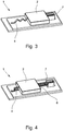
- the Figures 3 and 4 show the first embodiment of a thermal overload protection arrangement 1 in the first position and in the second position in a view from above.
- the second connection element 4 is arranged in such a way that it is arranged centrally opposite the actuator 7 on the overvoltage protection component 2. In this respect, it can be ensured that the overvoltage protection component 2 performs a linear movement from the first position into the second position.
- connection element 9 which mechanically connects the overvoltage protection component 2 to the carrier 5.
- the second connection element 4 and the actuator 7 are arranged on the same side of the overvoltage protection component 2.
- the thermal separation point is arranged essentially centrally below the overvoltage protection component. This also applies to all other exemplary embodiments. So that the displacement takes place uniformly in a straight line and not at an angle, the mechanical connection element 9 supporting the movement of the overvoltage protection component 2 is also arranged on the same side as the second connection element 4 and the actuator 7.
- FIG. 7 and 8 is a further embodiment of a thermal overload protection arrangement 1 in a first position ( Fig. 7 ) and in a second position ( Fig. 8 ) shown.
- the thermal connection element 4 is designed as a flexible stranded wire.
- FIGS. 9 and 10 show a fourth exemplary embodiment of a thermal overload protection arrangement 1, in which the second connection element 4 is designed as a resilient sheet metal that is compressed in the second position.
- the second connection element 4 itself is designed as a tension spring element and to that extent as an actuator 7, so that a further actuator element 7 can advantageously be dispensed with.
- connection element 4 is designed as a compression spring element and to this extent also as an actuator 7.
- an insulation 10 is additionally arranged between the second connection element 4, designed as a compression spring, and the carrier 5, the insulation 10 in particular in the in FIG Fig. 14
- the second position shown prevents the connection element 4 from coming into electrical contact with the first connection element 3 or the thermosensitive contact element 6.
- FIGS. 15 and 16 show a next exemplary embodiment of an overload protection arrangement 1, the actuator 7 being designed as a tension spring.
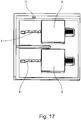
- the eighth exemplary embodiment of a thermal overload protection arrangement 1 shown has two overvoltage protection elements 2 which are arranged on a carrier 5 via two connection elements 3, 4.
- the two overvoltage protection components 2 are arranged in a housing 8.
- the housing 8 has a viewing window 11, the first overvoltage protection component 2 being arranged in the second position in front of the viewing window 11. In this respect, it can be seen outside the housing 8 when the first overvoltage protection component 2 has been moved due to a thermal overload.
- the illustrated embodiment has a display means 12 in the form of a slide, the slide being pushed in front of the viewing window 11 when at least one of the two overvoltage protection components 2 is moved from a first to a second position.
- the slide has a further fixing device 13 which, in the second position, prevents the overvoltage protection component 2 from moving back into the first position.
Landscapes
- Engineering & Computer Science (AREA)
- Microelectronics & Electronic Packaging (AREA)
- Physics & Mathematics (AREA)
- Electromagnetism (AREA)
- Chemical & Material Sciences (AREA)
- Combustion & Propulsion (AREA)
- Fuses (AREA)
- Emergency Protection Circuit Devices (AREA)
Abstract
Description
- Die Erfindung geht aus von einer Überlastschutzanordnung zum Schutz eines Überspannungsschutzbauelementes umfassend wenigstens ein Überspannungsschutzbauelement, zwei Anschlusselemente zum Anschluss des Überspannungsschutzbauelementes an den zu schützenden Strom- oder Signalpfad, einen Träger mit Stromführungselementen und wenigstens einen Aktor. wobei das erste Anschlusselement ein thermosensitives Kontaktelement umfasst. Das wenigstens eine Überspannungsschutzbauelement ist in einer ersten Position mit seinem ersten Pol über das thermosensitive Kontaktelement mit dem Träger derart verbunden ist, dass über das thermosensitive Kontaktelement eine elektrische Verbindung zu dem zu schützenden Stromkreis hergestellt ist. Außerdem ist der zweite Pol des Überspannungsschutzbauelementes über das zweite Anschlusselement mit einem Stromführungselement des Trägers verbunden ist. Bei einer thermischen Überbelastung des Überspannungsschutzbauelements ist das Überspannungsschutzbauelement durch den wenigstens einen Aktor in eine zweite Position verbringbar, in der der elektrische Kontakt über das thermosensitive Kontaktelement unterbrochen ist.
- Überspannungsschutzanordnungen werden seit Jahrzehnten in unterschiedlichen Ausführungsvarianten zum Schutz von elektrischen Stromkreisen, Anlagen, Maschinen und Geräten eingesetzt. Je nach Anwendungsfall und Schutzstufe weisen die Überspannungsschutzanordnungen dabei unterschiedliche Überspannungsschutzbauelemente und unterschiedliche Bauformen auf. Als Überspannungsschutzbauelemente können sowohl überspannungsbegrenzende Bauelemente wie Varistoren als auch überspannungsschaltende Bauelemente wie Funkenstrecken oder gasgefüllte Überspannungsableiter sowie Kombinationen dieser Bauelemente eingesetzt werden.
- Die Überbeanspruchung von solchen Überspannungsschutzbauelementen kann dazu führen, dass sie außerhalb ihres Nennbetriebsbereiches arbeiten. Der beispielsweise durch eine reduzierte Bauteilisolationsfestigkeit hervorgerufene Leistungsumsatz am geschädigten Bauteil kann dann zu einer unzulässigen Erwärmung führen. Wird die unzulässige Erwärmung des Bauelementes nicht verhindert, kann es zur vollständigen Zerstörung des Bauteils und infolge dessen zu einer Schädigung umgebender Materialien und Geräten, Entstehung von Rauchgasen oder zu einer Brandgefahr führen. Daher ist es üblich, derartigen Bauelementen eine Temperatursicherungen zuzuordnen, um eine Abschaltung des Bauelements bei Erwärmung zu ermöglichen.
- Aus der
DE 20 2011 110 007 U1 ist es bekannt, ein Überspannungsschutzbauelement, bei dem es sich insbesondere um einen Varistor handeln kann, auf einem Träger anzuordnen, wobei die beiden Anschlusselemente des Überspannungsschutzbauelementes über jeweils eine thermosensitive Lötverbindung mit einem Stromführungselement auf dem Träger und somit mit dem zu schützenden Stromkreis verbunden sind. Durch eine thermische Überlastung des Überspannungsschutzbauelements schmelzen die Lotverbindungen auf und das Überspannungsschutzbauelement wird durch einen Aktor, bei dem es sich insbesondere um ein Federelement handelt, in eine zweite Position verbracht. In dieser zweiten Position sind die elektrischen Verbindungen beider Anschlusselemente zu den Stromführungselementen getrennt, sodass im Ergebnis das Überspannungsschutzbauelement von dem Stromkreis abgetrennt ist. - Ausgehend von diesem Stand der Technik liegt der Erfindung die Aufgabe zugrunde eine Überlastschutzanordnung anzugeben, die besonders einfach ausgebildet ist und eine sichere Abtrennung gewährleistet.
- Diese Aufgabe ist bei der Überlastschutzanordnung mit den Merkmalen des Patentanspruchs 1 dadurch gelöst, dass das zweite Anschlusselement derart ausgebildet und angeordnet ist, dass es die Bewegung des Überspannungsschutzbauelementes von der ersten Position in die zweite Position ermöglicht.
- Erfindungsgemäß wurde erkannt, dass eine besonders einfache und sichere Abtrennung des Überspannungsschutzbauelementes von dem zu schützenden Stromkreis bei einer Überlastung dadurch erreicht werden kann, dass nur ein elektrischer Kontakt zwischen dem Überspannungsschutzbauelement und dem Stromkreis getrennt wird, während der mechanische Kontakt über das zweite Anschlusselement erhalten bleibt. Hierzu ist das zweite Anschlusselement derart ausgebildet und angeordnet, dass es die Bewegung des Überspannungsschutzbauelementes von der ersten Position in die zweite Position ermöglicht. Beispielsweise kann das zweite Anschlusselement hierzu während der Bewegung des Überspannungsschutzbauelementes eine Formänderung durchführen.
- Die erfindungsgemäße Ausführung der Überlastschutzanordnung hat den Vorteil, dass das Überspannungsschutzbauelement auch in der zweiten Position mit dem Träger über das zweite Anschlusselement mechanisch verbunden ist, sodass sich das Überspannungsschutzbauelement nach dem einseitigen Abtrennen nicht unkontrolliert in der Umgebung, beispielsweise in einem Gehäuse bewegt.
- Insofern weist die erfindungsgemäße Überlastschutzanordnung eine thermische Abtrenneinrichtung auf, die sichere elektrische Abtrennung des Überspannungsschutzbauelements von dem zu schützenden Stromkreis und eine definierte Positionierung und Bewegung des Überspannungsschutzbauelementes gewährleistet.
- Im Rahmen der vorliegenden Erfindung ist der Träger insbesondere als Leiterplatte ausgebildet, sodass es sich bei den Stromführungselementen um Leiterbahnen der Leiterplatte handelt.
- Besonders bevorzugt ist das thermosensitive Kontaktelement als Niedertemperaturlot ausgebildet, das bei einer thermischen Belastung ab einer bestimmten Temperatur schmilzt oder erweicht. Das zweite Anschlusselement kann dagegen beispielsweise über eine Standardlotverbindung mit dem Träger bzw. einer Leiterbahn bzw. einem Stromführungselement des Trägers verbunden sein. Hierdurch kann gewährleistet werden, dass der Kontakt über das zweite Anschlusselement auch bei einem Schmelzen oder Aufweichen des thermosensitiven Kontaktelementes bestehen bleibt.
- Gemäß einer Ausgestaltung der Überlastschutzanordnung ist das zweite Anschlusselement derart ausgebildet und angeordnet ist, dass es die Bewegung des Überspannungsschutzbauelementes von der ersten Position in die zweite Position unterstützt. Beispielsweise weist das zweite Anschlusselement hierzu in der ersten Position eine mechanische Vorspannung auf.
- Gemäß einer nächsten Ausgestaltung ist es vorteilhaft, wenn der wenigstens eine Aktor derart ausgestaltet und angeordnet ist, dass er das wenigstens eine Überspannungsschutzbauelement entlang der Oberfläche des Trägers bewegt. Vorzugsweise bewegt der Aktor das Überspannungsschutzbauelement im Wesentlichen parallel zur Oberfläche. Diese Ausgestaltung ist insbesondere im Hinblick auf die Ausbildung des zweiten Anschlusselementes vorteilhaft, da die Ermöglichung einer geradlinigen Bewegung von der ersten Position in die zweite Position durch ein Stauchen oder eine Strecken des Anschlusselementes besonders einfach realisiert werden kann. Denkbar ist jedoch ebenfalls, dass das Überspannungsschutzbauelement durch den wenigstens einen Aktor vertikal zur Oberfläche des Trägers oder auch schräg dazu bewegt werden kann.
- Gemäß einer Ausbildung der Überlastschutzanordnung sind das zweite Anschlusselement und der Aktor an gegenüberliegenden Seiten des Überspannungsschutzbauelementes angeordnet. Ebenfalls denkbar ist jedoch, dass das zweite Anschlusselement und der Aktor an derselben Seite des Überspannungsschutzbauelementes angeordnet sind.
- Neben dem zweiten Anschlusselement zur Herstellung einer elektrischen Verbindung des Überspannungsschutzbauelementes mit dem zu schützenden Stromkreis ist gemäß einer weiteren Ausfürhungsvariante wenigstens ein weiteres mechanisches Anschlusselement vorhanden, über das das Überspannungsschutzbauelement und dem Träger verbunden ist. Dieses wenigstens eine weitere mechanische Anschlusselement ist ebenfalls derart ausgebildet, dass es die Bewegung des Überspannungsschutzbauelementes von der ersten Position in die zweite Position beispielsweise durch eine Formänderung ermöglicht, vorzugsweise unterstützt. Beispielsweise kann das mechanische Anschlusselement identisch zu dem zweiten elektrischen Anschlusselement ausgebildet sein. Besonders bevorzugt ist das mechanische Anschlusselement derart ausgebildet und angeordnet, dass es eine definierte, vorzugsweise gleichförmige, Bewegung des Überspannungsschutzbauelementes von der ersten Position in die zweite Position unterstützt.
- Der wenigstens eine Aktor ist vorzugsweise als Federelement, insbesondere als Druckfeder oder als Zugfeder, ausgebildet. Ist das Federelement derart angeordnet, dass die Federkraft parallel zur Oberfläche des Trägers wirkt, so kann ein Verschieben des Überspannungschutzbauelementes entlang der Oberfläche besonders einfach realisiert werden.
- Gemäß einer besonders bevorzugten Ausgestaltung ist wenigstens ein Halteelement vorhanden, das das Überspannungsschutzbauelement im Wesentlichen in der zweiten Position hält. Wenn es heißt, dass das Überspannungsschutzbauelement im Wesentlichen in der zweiten Position gehalten wird, so ist damit gemeint, dass das Überspannungsschutzbauelement durch das Halteelement nicht starr fixiert sein muss, sondern dass kleinere Positionsänderungen zugelassen werden. Bevorzugt ist es jedoch, wenn das Überspannungsschutzbauelement durch das wenigstens eine Halteelement in der zweiten Position fixiert ist.
- Bei einer besonders bevorzugten Ausgestaltung ist bzw. sind das zweite Anschlusselement und/oder der Aktor als Halteelement ausgebildet. Das zweite Anschlusselement kann dazu als biegbares Anschlusselement, das vorzugsweise wenigstens eine Biegung oder zwei Biegungen aufweist, ausgebildet sein.
- Gemäß einer nächsten Ausgestaltung weist das biegbare Anschlusselement eine Vielzahl von Biegungen auf, sodass das Anschlusselement zumindest abschnittsweise federartig ausgebildet ist. Die Tolerierung der Bewegung von der ersten Position in die zweite Position erfolgt gemäß dieser Ausführung vorzugsweise durch ein Stauchen oder Strecken des federartig ausgebildeten Abschnittes. Das zweite Anschlusselement kann beispielsweise als flexible Litze, als flexibles Blech oder als Zugfederelement oder Druckfederelement ausgebildet sein.
- Besonders bevorzugt ist das zweite Anschlusselement selber als Aktor ausgebildet. In diesem Fall kann in vorteilhafter Weise auf ein zusätzliches als Aktor wirkendes Bauelement verzichtet werden. Denkbar ist ebenfalls, dass das zweite Anschlusselement als zweiter Aktor, also zusätzlich zu einem ersten Aktor, ausgebildet ist.
- Eine weitere vorteilhafte Ausgestaltung zeichnet sich dadurch aus, dass zumindest bereichsweise zwischen dem zweiten Anschlusselement und dem Träger eine, vorzugsweise verschiebbare, Isolierung angeordnet ist. Die Isolierung gewährleistet insbesondere, dass durch die Bewegung des Überspannungsschutzbauelementes bzw. die Formänderung des zweiten Anschlusselementes das zweite Anschlusselement keinen Kontakt mit dem in der zweiten Position freiliegenden ersten Anschlusselement bzw. dem thermosensitiven Kontaktelement aufweist.
- Gemäß einer vorteilhaften Ausgestaltung ist das wenigstens eine Überspannungsschutzbauelement in der ersten Position unter mechanischer Vorspannung, vorzugsweise durch den wenigstens einen Aktor und/oder durch das zweite Anschlusselement, auf dem Träger angeordnet. Schmilzt das thermosensitive Kontaktelement durch eine thermische Überbelastung, so wird das Überspannungsschutzbauelement unmittelbar in die zweite Position bewegt, wodurch der elektrische Kontakt über das thermosensitive Kontaktelement unterbrochen wird.
- Das Überspannungsschutzbauelement und der Träger sind vorzugsweise zumindest teilweise in einem Gehäuse angeordnet, wobei ein Anzeigemittel vorhanden ist, dessen Position anzeigt, ob das Überspannungsschutzbauelement in der ersten oder in der zweiten Position angeordnet ist. Hierzu ist in dem Gehäuse ein Sichtfenster angeordnet, so dass das Anzeigemittel zumindest in einer Position des Überspannungsschutzbauelement von außerhalb des Gehäuses erkennbar ist.
- Besonders bevorzug ist das Anzeigemittel an dem Überspannungsschutzbauelement, beispielsweise in Form einer farblichen Markierung, angeordnet und/oder das Anzeigemittel ist als separates Bauteil mit dem Überspannungsschutzbauelement verbunden. Im einfachsten Fall ist das Anzeigemittel durch das Überspannungsschutzbauelement selbst ausgebildet.
- Gemäß einer Ausgestaltung wird das Anzeigemittel durch die Bewegung des Überspannungsschutzbauelementes von der ersten Position in die zweite Position ebenfalls bewegt. Weist das Gehäuse ein Sichtfenster auf, wobei die Bewegung des Anzeigemittels durch das Sichtfenster wahrnehmbar ist, kann ein abgetrenntes Überspannungsschutzbauelement von außen leicht erfasst werden.
- Gemäß einer weiteren Ausbildung weist die Überlastschutzanordnung zwei Überspannungsschutzbauelemente auf, wobei auch das zweite Überspannungsschutzbauelement über zwei weitere Anschlusselemente auf dem Träger angeordnet ist. Das erste Anschlusselement des zweiten Überspannungsschutzbauelementes umfasst ebenfalls ein thermosensitives Kontaktelement. Das zweite Überspannungsschutzbauelement ist dabei in der ersten Position mit seinem ersten Pol über das thermosensitive Kontaktelement mit dem Träger derart verbunden, dass über das thermosensitive Kontaktelement eine elektrische Verbindung zu dem zu schützenden Stromkreis hergestellt ist. Der zweite Pol des zweiten Überspannungsschutzbauelementes ist über das zweite Anschlusselement mit einem Stromführungselement des Träger verbunden, wobei das zweite Überspannungsschutzbauelement bei einer thermischen Überbelastung durch einen Aktor in eine zweite Position verbringbar ist, in der der elektrische Kontakt über das thermosensitive Kontaktelement unterbrochen ist. Das zweite Anschlusselement ist dabei derart ausgebildet und angeordnet, dass es die Bewegung des Überspannungsschutzbauelementes von der ersten Position in die zweite Position ermöglicht. Der Träger und die beiden Überspannungsschutzbauelemente sind dabei zumindest teilweise in einem Gehäuse angeordnet, wobei ein Anzeigemittel vorhanden ist, durch dessen Positionvon außerhalb des Gehäuses erkennbar ist, ob wenigstens ein Überspannungsschutzbauelement in der zweiten Position angeordnet ist.
- Gemäß einer Ausgestaltung der zuvor beschriebenen Überlastschutzanordnung umfassend zwei Überspannungsschutzbauelemente ist das Anzeigemittel als Schieber ausgebildet, der bewegt wird, sobald eines der Überspannungsschutzbauelemente auf Grund einer thermischen Überbelastung in die zweite Position verbracht wird. Weist das Gehäuse ein Sichtfenster auf, so ist das Anzeigemittel bzw. der Schieber vorzugweise derart angeordnet, dass der Schieber vor das Sichtfenster geschoben wird, wenn wenigstens eines der beiden Überspannungsschutzbauelemente von einer ersten in eine zweite Position bewegt wird. Zusätzlich weist der Schieber gemäß einer weiteren Ausgestaltung eine weitere Fixierungseinrichtung auf, die in der zweiten Position verhindert, dass das Überspannungsschutzbaulement sich zurück in die ersten Position bewegt.
- Im Einzelnen gibt es nun eine Vielzahl von Möglichkeiten, die erfindungsgemäße Überlastschutzanordnung auszugestalten und weiterzubilden. Dazu wird verwiesen sowohl auf die dem unabhängigen Patentanspruch nachgeordneten Patentansprüche als auch auf die nachfolgende Beschreibung von bevorzugten Ausführungsbeispielen in Verbindung mit der Zeichnung. In der Zeichnung zeigen
- Fig. 1
- ein erstes Ausführungsbeispiel einer erfindungsgemäßen Überlastschutzanordnung in einer ersten Position, in einer Schnittansicht,
- Fig. 2
- die Überlastschutzanordnung gemäß
Fig. 1 , in einer zweiten Position in einer Schnittansicht, - Fig. 3
- das erste Ausführungsbeispiel in der ersten Position in einer Ansicht von oben,
- Fig. 4
- das erste Ausführungsbeispiel in der zweiten Position in einer Ansicht von oben,
- Fig. 5
- ein zweites Ausführungsbeispiel einer erfindungsgemäßen Überlastschutzanordnung in einer ersten Position,
- Fig. 6
- das zweite Ausführungsbeispiel in einer zweiten Position,
- Fig. 7
- ein drittes Ausführungsbeispiel einer erfindungsgemäßen Überlastschutzanordnung in einer ersten Position,
- Fig. 8
- das dritte Ausführungsbeispiel in einer zweiten Position,
- Fig. 9
- ein viertes Ausführungsbeispiel einer erfindungsgemäßen Überlastschutzanordnung in einer ersten Position,
- Fig. 10
- das vierte Ausführungsbeispiel in einer zweiten Position,
- Fig. 11
- ein fünftes Ausführungsbeispiel einer erfindungsgemäßen Überlastschutzanordnung in einer ersten Position,
- Fig. 12
- das fünfte Ausführungsbeispiel in einer zweiten Position,
- Fig. 13
- ein sechstes Ausführungsbeispiel einer erfindungsgemäßen Überlastschutzanordnung in einer ersten Position,
- Fig. 14
- das sechste Ausführungsbeispiel in einer zweiten Position,
- Fig. 15
- ein siebtes Ausführungsbeispiel einer erfindungsgemäßen Überlastschutzanordnung in ersten Position,
- Fig. 16
- das siebte Ausführungsbeispiel in einer zweiten Position,
- Fig. 17
- ein achtes Ausführungsbeispiel einer erfindungsgemäßen Überlastschutzanordnung,
- Fig. 18
- ein neuntes Ausführungsbeispiel einer erfindungsgemäßen Überlastschutzanordnung in einer ersten Position und
- Fig. 19
- das neunte Ausführungsbeispiel in einer zweiten Position.
-
Fig. 1 zeigt ein erstes Ausführungsbeispiel einer Überlastschutzanordnung 1 zum Schutz eines Überspannungsschutzbauelementes 2 in einer Schnittansicht. Die Überlastschutzanordnung 1 umfasst ein Überspannungsschutzbauelement 2, das über ein erstes Anschlusselement 3 und über ein zweites Anschlusselement 4 mit auf dem Träger 5, der hier als Leiterplatte ausgebildet ist, angeordneten Stromführungselementen elektrisch verbunden ist. - Das erste Anschlusselement 3 umfasst im dargestellten Ausführungsbeispiel ein thermosensitives Kontaktelement 6. Im Detail ist das in
Fig. 1 gezeigte thermosensitive Kontaktelement 6 als Niedertemperaturlot ausgestaltet und bildet insofern eine thermische Abtrennstelle des Überspannungsschutzbauelementes 2. Bei einer thermischen Überbelastung schmilzt das thermosensitive Kontaktelement 6 auf, wodurch die durch das Kontaktelement 6 gebildete mechanische Verbindung getrennt wird. - Zudem ist ein Aktor 7 in Form einer Druckfeder vorhanden, wobei der Aktor 7 in der dargestellten ersten Position unter mechanischer Vorspannung gegenüber dem Gehäuse 8 montiert ist. Löst sich die mechanische Verbindung, die durch das thermosensitive Kontaktelement 6 hergestellt ist, so verschiebt der Aktor 7 das Überspannungsschutzbauelement 2 entlang der Oberfläche des Trägers 5 in eine zweite Position. Dies ist in
Fig. 2 dargestellt. - Das zweite Anschlusselement 4 ist über eine Standardlotverbindung mit dem Träger 5 verbunden. Zudem ist das zweite Anschlusselement 4 abschnittsweise federartig ausgebildet. Das zweite Anschlusselement 4 und der die als Aktor 7 wirkende Druckfeder sind an dem Überspannungsschutzbauelement einander gegenüberliegend angeordnet.
- Die Darstellung in
Fig. 2 zeigt die zweite Position des Überspannungsschutzbauelementes 2. In dieser Position ist die elektrische Verbindung über das thermosensitive Kontaktelement 6 auf Grund der Verschiebung des Überspannungsschutzbauelementes 2 unterbrochen. Das zweite Anschlusselement 4 hat sich durch die Bewegung des Überspannungsschutzbauelementes 2 verformt, im Detail wurde der federartig ausgebildete Teil des Anschlusselementes 4 gestaucht. Das zweite Anschlusselement 4 ist damit auch in der zweiten Position mit dem Träger 5 und dem Überspannungsschutzbauelement 2 verbunden. - Die dargestellte Ausgestaltung der Überlastschutzanordnung 1 weist damit den Vorteil auf, dass sowohl während der Bewegung als auch in der zweiten Position über das zweite Anschlusselement 4 eine mechanische Verbindung des Überspannungsschutzbaulementes 2 zu dem Träger 5 besteht, wodurch einerseits eine definierte Bewegung von der ersten Position in die zweite Position gewährleistet werden kann und wodurch weiterhin garantiert ist, dass das Überspannungsschutzbauelement 2 nach der Trennung der mechanischen Verbindung über das thermosensitive Kontaktelement 6 sich nicht unkontrolliert im Gehäuse 8 bewegt.
- Die
Fig. 3 und 4 zeigen das erste Ausführungsbeispiel einer thermischen Überlastschutzanordnung 1 in der ersten Position und in der zweiten Position in einer Ansicht von oben. Das zweite Anschlusselement 4 ist in dem dargestellten Ausführungsbeispiel derart angeordnet, dass es mittig gegenüberliegend von dem Aktor 7 an dem Überspannungsschutzbauelement 2 angeordnet ist. Insofern kann gewährleistet werden, dass das Überspannungsschutzbauelement 2 eine geradlinige Bewegung von der ersten Position in die zweite Position durchführt. - In dem in
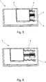
Fig. 5 gezeigten zweiten Ausführungsbeispiel einer Überlastschutzanordnung 1 ist neben dem zweiten Anschlusselement 4 ein weiteres mechanisches Anschlusselement 9 vorhanden, das das Überspannungsschutzbauelement 2 mit dem Träger 5 mechanisch verbindet. Im Unterschied zu dem in denFig. 1 bis 4 dargestellten Ausführungsbeispiel sind das zweite Anschlusselement 4 und der Aktor 7 auf derselben Seite des Überspannungsschutzbauelementes 2 angeordnet. In der zweiten Position wird das zweite Anschlusselement im Gegensatz zu den vorherigen Darstellungen gestreckt und nicht gestaucht. Nicht zu sehen ist, dass die thermische Trennstelle ebenso wie in dem ersten Ausführungsbeispiel im Wesentlichen mittig unterhalb des Überspannungsschutzbauelementes angeordnet ist. Dies gilt ebenso für sämtliche weiteren Ausführungsbeispiele. Damit die Verschiebung gleichförmig geradlinig und nicht schief erfolgt, ist das die Bewegung des Überspannungsschutzbauelementes 2 unterstützende mechanische Anschlusselement 9 ebenfalls auf der derselben Seite wie das zweite Anschlusselement 4 und der Aktor 7 angeordnet. - In den
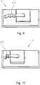
Fig. 7 und 8 ist ein weiteres Ausführungsbeispiel einer thermischen Überlastschutzanordnung 1 in einer ersten Position (Fig. 7 ) und in einer zweiten Position (Fig. 8 ) dargestellt. In dem dargestellten Ausführungsbeispiel ist das thermische Anschlusselement 4 als flexible Litze ausgebildet. - Die
Fig. 9 und 10 zeigen ein viertes Ausführungsbeispiel einer thermischen Überlastschutzanordnung 1, in der das zweite Anschlusselement 4 als federndes Blech ausgebildet ist, das in der zweiten Position gestaucht ist. Zudem ist das zweite Anschlusselement 4 selbst als Zugfederelement und insofern als Aktor 7 ausgebildet, sodass in vorteilhafter Weise auf eine weiteres Aktorelement 7 verzichtet werden kann. - In dem in den
Fig. 11 und 12 dargestellten fünften Ausführungsbeispiel ist das zweite Anschlusselement 4 als Druckfederelement und insofern ebenfalls als Aktor 7 ausgebildet. - In dem in den
Fig. 13 und 14 dargestellten Ausführungsbeispiel ist zusätzlich eine Isolierung 10 zwischen dem als Druckfeder ausgebildeten zweiten Anschlusselement 4 und dem Träger 5 angeordnet, wobei die Isolierung 10 insbesondere in der inFig. 14 gezeigten zweiten Position verhindert, dass das Anschlusselement 4 in elektrischen Kontakt mit dem ersten Anschlusselement 3 bzw. dem thermosensitiven Kontaktelement 6 gerät. - Die
Fig. 15 und 16 zeigen ein nächstes Ausführungsbeispiel einer Überlastschutzanordnung 1, wobei der Aktor 7 als Zugfeder ausgebildet ist. - Das in dem in
Fig. 17 dargestellte achte Ausführungsbeispiel einer thermischen Überlastschutzanordnung 1 weist zwei Überspannungsschutzelemente 2 auf, die gleichermaßen über zwei Anschlusselemente 3, 4 auf einem Träger 5 angeordnet sind. Die beiden Überspannungsschutzbauelement 2 sind in einem Gehäuse 8 angeordnet. Das Gehäuse 8 weist ein Sichtfenster 11 auf, wobei das erste Überspannungsschutzbauelement 2 in der zweiten Position vor dem Sichtfenster 11 angeordnet ist. Insofern ist außerhalb des Gehäuses 8 erkennbar, wenn das erste Überspannungsschutzbauelement 2 aufgrund einer thermischen Überbelastung bewegt wurde. - In Erweiterung dazu weist das in den
Fig. 18 und 19 dargestellte Ausführungsbeispiel ein Anzeigemittel 12 in Form eines Schiebers auf, wobei der Schieber vor das Sichtfenster 11 geschoben wird, wenn wenigstens eines der beiden Überspannungsschutzbauelemente 2 von einer ersten in eine zweite Position bewegt wird. Zusätzlich weist der Schieber eine weitere Fixierungseinrichtung 13 auf, die in der zweiten Position verhindert, dass das Überspannungsschutzbaulement 2 sich zurück in die ersten Position bewegt. -
- 1
- Überlastschutzanordnung
- 2
- Überspannungsschutzbauelement
- 3
- erstes Anschlusselement
- 4
- zweites Anschlusselement
- 5
- Träger
- 6
- thermosensitives Kontaktelement
- 7
- Aktor
- 8
- Gehäuse
- 9
- mechanisches Anschlusselement
- 10
- Isolierung
- 11
- Sichtfenster
- 12
- Anzeigemittel
- 13
- Fixierungseinrichtung
Claims (13)
- Überlastschutzanordnung (1) zum Schutz eines Überspannungsschutzbauelementes (2) umfassend wenigstens ein Überspannungsschutzbauelement (2), zwei Anschlusselemente (3, 4) zum Anschluss des Überspannungsschutzbauelementes (2) an den zu schützenden Strom- oder Signalpfad, einen Träger (5) mit Stromführungselementen und wenigstens einen Aktor (7),
wobei das erste Anschlusselement (3) ein thermosensitives Kontaktelement (6) umfasst,
wobei das wenigstens eine Überspannungsschutzbauelement (2) in einer ersten Position mit seinem ersten Pol über das thermosensitive Kontaktelement (6) mit dem Träger (5) derart verbunden ist, dass über das thermosensitive Kontaktelement (6) eine elektrische Verbindung zu dem zu schützenden Stromkreis herstellbar ist,
wobei der zweite Pol des Überspannungsschutzbauelementes (2) über das zweite Anschlusselement (4) mit einem Stromführungselement des Trägers (5) verbunden ist, und
wobei das wenigstens eine Überspannungsschutzbauelement (2) bei einer thermischen Überbelastung durch den wenigstens einen Aktor (7) in eine zweite Position verbringbar ist, in der der elektrische Kontakt über das thermosensitive Kontaktelement (6) unterbrochen ist,
dadurch gekennzeichnet,
dass das zweite Anschlusselement (4) derart ausgebildet und angeordnet ist, dass es die Bewegung des Überspannungsschutzbauelementes (2) von der ersten Position in die zweite Position ermöglicht. - Überlastungsschutzanordnung (1) nach Anspruch 1, dadurch gekennzeichnet, dass das zweite Anschlusselement (4) derart ausgebildet und angeordnet ist, dass es die Bewegung des Überspannungsschutzbauelementes (2) von der ersten Position in die zweite Position unterstützt.
- Überlastungsschutzanordnung (1) nach Anspruch 1 oder 2, dadurch gekennzeichnet, dass der wenigstens eine Aktor (7) derart ausgestaltet und angeordnet ist, dass er das wenigstens eine Überspannungsschutzbauelement (2) entlang der Oberfläche des Trägers (5) bewegt.
- Überlastungsschutzanordnung (1) nach einem der Ansprüche 1 bis 3, dadurch gekennzeichnet, dass der Aktor (7) als Federelement, vorzugsweise als Druckfeder oder als Zugfeder, ausgebildet ist.
- Überlastungsschutzanordnung (1) nach einem der Ansprüche 1 bis 4, dadurch gekennzeichnet, dass wenigstens ein Halteelement vorhanden ist, das das Überspannungsschutzbauelement (2) nach einer thermischen Überbelastung im Wesentlichen in der zweiten Position hält.
- Überlastungsschutzanordnung (1) nach Anspruch 5, dadurch gekennzeichnet, dass das zweite Anschlusselement (4) und/oder der Aktor (7) als Halteelement ausgebildet ist bzw. sind.
- Überlastungsschutzanordnung (1) nach einem der Ansprüche 1 bis 6, dadurch gekennzeichnet, dass das zweite Anschlusselement (4) als biegbares Anschlusselement, das vorzugsweise wenigstens eine Biegung aufweist, ausgebildet ist.
- Überlastungsschutzanordnung (1) nach einem der Ansprüche 1 bis 7, dadurch gekennzeichnet, dass das zweite Anschlusselement (4) als flexible Litze und/oder als flexibles Blech und/oder als Zugfederelement und/oder als Druckfederelement ausgebildet ist.
- Überlastungsschutzanordnung (1) nach einem der Ansprüche 1 bis 7, dadurch gekennzeichnet, dass das zweite Anschlusselement (4) als Aktor (7) ausgebildet ist.
- Überlastungsschutzanordnung (1) nach einem der Ansprüche 1 bis 9, dadurch gekennzeichnet, dass das wenigstens eine Überspannungsschutzbauelement (2) in der ersten Position unter mechanischer Vorspannung angeordnet ist.
- Überlastungsschutzanordnung (1) nach einem der Ansprüche 1 bis 10, dadurch gekennzeichnet, dass das Überspannungsschutzbauelement (2) und der Träger (5) zumindest teilweise in einem Gehäuse (8) angeordnet sind, wobei ein Anzeigemittel (11) vorhanden ist, durch dessen Position von außerhalb des Gehäuses (8) erkennbar ist, ob das Überspannungsschutzbauelement (2) in der ersten oder der zweiten Position angeordnet ist.
- Überlastschutzanordnung (1) nach Anspruch 11, dadurch gekennzeichnet, dass das Anzeigemittel (11) an dem Überspannungsschutzbauelement (2) angeordnet ist und/oder dass das Anzeigemittel (11) als separates Bauteil mit dem Überspannungsschutzbauelement (2) verbunden ist.
- Überlastschutzanordnung (1) nach einem der Ansprüche 1 bis 12, dadurch gekennzeichnet, dass ein zweites Überspannungsschutzbauelement (2) über zwei weitere Anschlusselemente (3, 4) auf dem Träger (5) angeordnet ist,
wobei das erste Anschlusselement (3) des zweiten Überspannungsschutzbauelementes (2) ein thermosensitives Kontaktelement (6) umfasst,
wobei das zweite Überspannungsschutzbauelement (2) in der ersten Position mit seinem ersten Pol über das thermosensitive Kontaktelement (6) mit dem Träger (5) derart verbunden ist, dass über das thermosensitive Kontaktelement (6) eine elektrische Verbindung zu dem zu schützenden Stromkreis hergestellt ist,
wobei weiterhin der zweite Pol des zweiten Überspannungsschutzbauelementes (2) über das zweite Anschlusselement (4) mit einem Stromführungselement des Träger (5) verbunden ist,
wobei das zweite Überspannungsschutzbauelement (2) bei einer thermischen Überbelastung durch einen Aktor (7) in eine zweite Position verbringbar ist, in der der elektrische Kontakt über das thermosensitive Kontaktelement (6) unterbrochen ist,
wobei das zweite Anschlusselement (4) derart ausgebildet und angeordnet ist, dass es die Bewegung des Überspannungsschutzbauelementes (2) von der ersten Position in die zweite Position ermöglicht,
wobei der Träger (5) und das erste Überspannungsschutzbauelement (2) und das zweite Überspannungsschutzbauelement (2) zumindest teilweise in einem Gehäuse (8) angeordnet sind und
wobei ein Anzeigemittel (11) vorhanden ist, wobei durch die Position des Anzeigemittels außerhalb des Gehäuses (8) erkennbar ist, ob wenigstens ein Überspannungsschutzbauelement (2) in der zweiten Position angeordnet ist.
Applications Claiming Priority (1)
| Application Number | Priority Date | Filing Date | Title |
|---|---|---|---|
| DE102019114424.8A DE102019114424A1 (de) | 2019-05-29 | 2019-05-29 | Überlastschutzanordnung |
Publications (2)
| Publication Number | Publication Date |
|---|---|
| EP3745432A1 true EP3745432A1 (de) | 2020-12-02 |
| EP3745432B1 EP3745432B1 (de) | 2023-12-06 |
Family
ID=70682699
Family Applications (1)
| Application Number | Title | Priority Date | Filing Date |
|---|---|---|---|
| EP20174300.2A Active EP3745432B1 (de) | 2019-05-29 | 2020-05-13 | Überlastschutzanordnung |
Country Status (3)
| Country | Link |
|---|---|
| EP (1) | EP3745432B1 (de) |
| CN (1) | CN112017920B (de) |
| DE (1) | DE102019114424A1 (de) |
Citations (4)
| Publication number | Priority date | Publication date | Assignee | Title |
|---|---|---|---|---|
| DE19626275A1 (de) * | 1996-06-29 | 1998-01-02 | Tridelta Ueberspannungsableite | Niederspannungsableiter |
| EP1467603A1 (de) * | 2003-04-08 | 2004-10-13 | Valeo Climatisation | Schutz gegen Kurzschlüssen auf einer Leiterplatte |
| US8009401B2 (en) * | 2008-02-27 | 2011-08-30 | Schneider Electric Industries Sas | Voltage surge protection device comprising selective disconnection means |
| DE202011110007U1 (de) | 2010-08-06 | 2012-10-08 | Phoenix Contact Gmbh & Co. Kg | Thermische Überlastschutzanordnung |
Family Cites Families (11)
| Publication number | Priority date | Publication date | Assignee | Title |
|---|---|---|---|---|
| FR2848353B1 (fr) * | 2002-12-10 | 2005-06-17 | Soule Protection Surtensions | Dispositif de protection contre des surtensions |
| DE102008057166B4 (de) * | 2008-11-13 | 2020-03-12 | Behr-Hella Thermocontrol Gmbh | Elektrische Schaltung mit Übertemperaturschutz |
| FR2958787B1 (fr) * | 2010-04-09 | 2012-05-11 | Abb France | Dispositif de protection contre les surtensions a deconnecteurs thermiques dedoubles |
| DE102013006052B4 (de) * | 2013-02-08 | 2016-08-04 | DEHN + SÖHNE GmbH + Co. KG. | Überspannungsschutzgerät |
| FR3003394B1 (fr) * | 2013-03-12 | 2015-03-06 | Hager Electro Sas | Actionneur magnetothermique. |
| DE102015000329B3 (de) * | 2015-01-09 | 2016-05-19 | DEHN + SÖHNE GmbH + Co. KG. | Überspannungsschutzgerät mit im thermischen Überlastfall aktivierter mechanischer Abtrennvorrichtung |
| DE102015014163A1 (de) * | 2015-09-08 | 2017-03-09 | DEHN + SÖHNE GmbH + Co. KG. | Vorrichtung zum thermischen Auslösen, Abtrennen und/oder Signalisieren des Zustandes eines Überspannungsschutzgerätes |
| CN206163439U (zh) * | 2016-10-17 | 2017-05-10 | 广西新全通电子技术有限公司 | 一种新型的电涌保护装置 |
| DE102017105029B4 (de) * | 2017-03-09 | 2019-10-31 | Phoenix Contact Gmbh & Co. Kg | Abschaltelement und Überspannungsschutzanordnung mit einem Abschaltelement |
| DE102017112281A1 (de) * | 2017-06-02 | 2018-12-06 | Eaton Electrical Ip Gmbh & Co. Kg | Schutz-Vorrichtung sowie Anordnung mit einer solchen Schutz-Vorrichtung, einem elektrischen Motor und einer Stromversorgung |
| DE102017124224B4 (de) * | 2017-10-18 | 2023-03-02 | Phoenix Contact Gmbh & Co. Kg | Überspannungsschutzgerät |
-
2019
- 2019-05-29 DE DE102019114424.8A patent/DE102019114424A1/de active Pending
-
2020
- 2020-05-13 EP EP20174300.2A patent/EP3745432B1/de active Active
- 2020-05-29 CN CN202010475603.2A patent/CN112017920B/zh active Active
Patent Citations (4)
| Publication number | Priority date | Publication date | Assignee | Title |
|---|---|---|---|---|
| DE19626275A1 (de) * | 1996-06-29 | 1998-01-02 | Tridelta Ueberspannungsableite | Niederspannungsableiter |
| EP1467603A1 (de) * | 2003-04-08 | 2004-10-13 | Valeo Climatisation | Schutz gegen Kurzschlüssen auf einer Leiterplatte |
| US8009401B2 (en) * | 2008-02-27 | 2011-08-30 | Schneider Electric Industries Sas | Voltage surge protection device comprising selective disconnection means |
| DE202011110007U1 (de) | 2010-08-06 | 2012-10-08 | Phoenix Contact Gmbh & Co. Kg | Thermische Überlastschutzanordnung |
Also Published As
| Publication number | Publication date |
|---|---|
| CN112017920A (zh) | 2020-12-01 |
| DE102019114424A1 (de) | 2020-12-03 |
| EP3745432B1 (de) | 2023-12-06 |
| CN112017920B (zh) | 2023-05-12 |
Similar Documents
| Publication | Publication Date | Title |
|---|---|---|
| EP1587188B1 (de) | Überspannungsschutzgerät | |
| DE3323687C2 (de) | Überspannungsableitermagazin für Anschlußleisten der Fernmeldetechnik | |
| DE102008031917B4 (de) | Überspannungschutzelement | |
| DE102009036125A1 (de) | Überspannungsschutzelement | |
| DE202014103262U1 (de) | Überspannungsschutzelement | |
| DE102007004342A1 (de) | Steckbarer Überspannungsableiter | |
| DE202009013505U1 (de) | Überspannungsschutzelement | |
| EP2038972B1 (de) | Gerät zum schutz gegen überspannungen für elektrische anlagen | |
| EP2280457A2 (de) | Überspannungsschutzelement | |
| DE102017124224B4 (de) | Überspannungsschutzgerät | |
| DE202016102520U1 (de) | Kostengünstige thermische Abtrennvorrichtung für eine elektrische Komponente | |
| DE102009008386B4 (de) | Elektronisches Gerät und Kontaktelement zur Verwendung in einem elektronischen Gerät | |
| DE102012024352A1 (de) | Überspannungsschutzgerät | |
| DE202007006934U1 (de) | Steckbarer Überspannungsableiter | |
| DE19722580C1 (de) | Überspannungsschutzstecker mit Fail-Safe | |
| EP3745432B1 (de) | Überlastschutzanordnung | |
| DE102019112680B4 (de) | Überspannungsschutzgerät | |
| DE102017112429B4 (de) | Überspannungsschutzelement | |
| EP0862197B1 (de) | Schutzstecker | |
| DE202019103666U1 (de) | Überspannungsschutzelement und Überspannungsschutzgerät | |
| DE19816907A1 (de) | Schutzstecker für eine Einrichtung der Telekommunikationstechnik | |
| DE102007024622B4 (de) | Überspannungsschutzeinrichtung | |
| DE102017131154B4 (de) | Überspannungsschutzanordnung | |
| DE202020103719U1 (de) | Überspannungsschutzelement und Überspannungsschutzgerät | |
| DE19620340C1 (de) | Überspannungs - Schutzstecker |
Legal Events
| Date | Code | Title | Description |
|---|---|---|---|
| PUAI | Public reference made under article 153(3) epc to a published international application that has entered the european phase |
Free format text: ORIGINAL CODE: 0009012 |
|
| STAA | Information on the status of an ep patent application or granted ep patent |
Free format text: STATUS: THE APPLICATION HAS BEEN PUBLISHED |
|
| AK | Designated contracting states |
Kind code of ref document: A1 Designated state(s): AL AT BE BG CH CY CZ DE DK EE ES FI FR GB GR HR HU IE IS IT LI LT LU LV MC MK MT NL NO PL PT RO RS SE SI SK SM TR |
|
| AX | Request for extension of the european patent |
Extension state: BA ME |
|
| STAA | Information on the status of an ep patent application or granted ep patent |
Free format text: STATUS: REQUEST FOR EXAMINATION WAS MADE |
|
| 17P | Request for examination filed |
Effective date: 20210602 |
|
| RBV | Designated contracting states (corrected) |
Designated state(s): AL AT BE BG CH CY CZ DE DK EE ES FI FR GB GR HR HU IE IS IT LI LT LU LV MC MK MT NL NO PL PT RO RS SE SI SK SM TR |
|
| P01 | Opt-out of the competence of the unified patent court (upc) registered |
Effective date: 20230512 |
|
| GRAP | Despatch of communication of intention to grant a patent |
Free format text: ORIGINAL CODE: EPIDOSNIGR1 |
|
| STAA | Information on the status of an ep patent application or granted ep patent |
Free format text: STATUS: GRANT OF PATENT IS INTENDED |
|
| RIC1 | Information provided on ipc code assigned before grant |
Ipc: H01C 7/12 20060101ALI20230622BHEP Ipc: H05K 1/18 20060101ALI20230622BHEP Ipc: H01H 37/76 20060101ALI20230622BHEP Ipc: H01H 1/40 20060101AFI20230622BHEP |
|
| INTG | Intention to grant announced |
Effective date: 20230707 |
|
| GRAS | Grant fee paid |
Free format text: ORIGINAL CODE: EPIDOSNIGR3 |
|
| GRAA | (expected) grant |
Free format text: ORIGINAL CODE: 0009210 |
|
| STAA | Information on the status of an ep patent application or granted ep patent |
Free format text: STATUS: THE PATENT HAS BEEN GRANTED |
|
| AK | Designated contracting states |
Kind code of ref document: B1 Designated state(s): AL AT BE BG CH CY CZ DE DK EE ES FI FR GB GR HR HU IE IS IT LI LT LU LV MC MK MT NL NO PL PT RO RS SE SI SK SM TR |
|
| REG | Reference to a national code |
Ref country code: GB Ref legal event code: FG4D Free format text: NOT ENGLISH |
|
| REG | Reference to a national code |
Ref country code: CH Ref legal event code: EP |
|
| REG | Reference to a national code |
Ref country code: DE Ref legal event code: R096 Ref document number: 502020006257 Country of ref document: DE |
|
| REG | Reference to a national code |
Ref country code: IE Ref legal event code: FG4D Free format text: LANGUAGE OF EP DOCUMENT: GERMAN |
|
| REG | Reference to a national code |
Ref country code: LT Ref legal event code: MG9D |
|
| PG25 | Lapsed in a contracting state [announced via postgrant information from national office to epo] |
Ref country code: GR Free format text: LAPSE BECAUSE OF FAILURE TO SUBMIT A TRANSLATION OF THE DESCRIPTION OR TO PAY THE FEE WITHIN THE PRESCRIBED TIME-LIMIT Effective date: 20240307 |
|
| PG25 | Lapsed in a contracting state [announced via postgrant information from national office to epo] |
Ref country code: LT Free format text: LAPSE BECAUSE OF FAILURE TO SUBMIT A TRANSLATION OF THE DESCRIPTION OR TO PAY THE FEE WITHIN THE PRESCRIBED TIME-LIMIT Effective date: 20231206 |
|
| PG25 | Lapsed in a contracting state [announced via postgrant information from national office to epo] |
Ref country code: ES Free format text: LAPSE BECAUSE OF FAILURE TO SUBMIT A TRANSLATION OF THE DESCRIPTION OR TO PAY THE FEE WITHIN THE PRESCRIBED TIME-LIMIT Effective date: 20231206 |
|
| PG25 | Lapsed in a contracting state [announced via postgrant information from national office to epo] |
Ref country code: LT Free format text: LAPSE BECAUSE OF FAILURE TO SUBMIT A TRANSLATION OF THE DESCRIPTION OR TO PAY THE FEE WITHIN THE PRESCRIBED TIME-LIMIT Effective date: 20231206 Ref country code: GR Free format text: LAPSE BECAUSE OF FAILURE TO SUBMIT A TRANSLATION OF THE DESCRIPTION OR TO PAY THE FEE WITHIN THE PRESCRIBED TIME-LIMIT Effective date: 20240307 Ref country code: ES Free format text: LAPSE BECAUSE OF FAILURE TO SUBMIT A TRANSLATION OF THE DESCRIPTION OR TO PAY THE FEE WITHIN THE PRESCRIBED TIME-LIMIT Effective date: 20231206 Ref country code: BG Free format text: LAPSE BECAUSE OF FAILURE TO SUBMIT A TRANSLATION OF THE DESCRIPTION OR TO PAY THE FEE WITHIN THE PRESCRIBED TIME-LIMIT Effective date: 20240306 |
|
| PG25 | Lapsed in a contracting state [announced via postgrant information from national office to epo] |
Ref country code: NL Free format text: LAPSE BECAUSE OF FAILURE TO SUBMIT A TRANSLATION OF THE DESCRIPTION OR TO PAY THE FEE WITHIN THE PRESCRIBED TIME-LIMIT Effective date: 20231206 |