EP3745232A1 - Automatisches fahrsystem - Google Patents
Automatisches fahrsystem Download PDFInfo
- Publication number
- EP3745232A1 EP3745232A1 EP18902412.8A EP18902412A EP3745232A1 EP 3745232 A1 EP3745232 A1 EP 3745232A1 EP 18902412 A EP18902412 A EP 18902412A EP 3745232 A1 EP3745232 A1 EP 3745232A1
- Authority
- EP
- European Patent Office
- Prior art keywords
- wireless information
- travel
- automated vehicle
- tag
- information tag
- Prior art date
- Legal status (The legal status is an assumption and is not a legal conclusion. Google has not performed a legal analysis and makes no representation as to the accuracy of the status listed.)
- Withdrawn
Links
- 238000001514 detection method Methods 0.000 abstract description 12
- 238000010586 diagram Methods 0.000 description 9
- 238000000034 method Methods 0.000 description 9
- 235000013399 edible fruits Nutrition 0.000 description 8
- 238000005507 spraying Methods 0.000 description 6
- 238000003306 harvesting Methods 0.000 description 5
- 239000003337 fertilizer Substances 0.000 description 3
- 230000004308 accommodation Effects 0.000 description 2
- 239000004009 herbicide Substances 0.000 description 2
- 239000002420 orchard Substances 0.000 description 2
- 239000000575 pesticide Substances 0.000 description 2
- 239000007921 spray Substances 0.000 description 2
- 240000007594 Oryza sativa Species 0.000 description 1
- 235000007164 Oryza sativa Nutrition 0.000 description 1
- 239000002390 adhesive tape Substances 0.000 description 1
- 235000009566 rice Nutrition 0.000 description 1
Images


Classifications
-
- G—PHYSICS
- G05—CONTROLLING; REGULATING
- G05D—SYSTEMS FOR CONTROLLING OR REGULATING NON-ELECTRIC VARIABLES
- G05D1/00—Control of position, course, altitude or attitude of land, water, air or space vehicles, e.g. using automatic pilots
- G05D1/02—Control of position or course in two dimensions
- G05D1/021—Control of position or course in two dimensions specially adapted to land vehicles
- G05D1/0259—Control of position or course in two dimensions specially adapted to land vehicles using magnetic or electromagnetic means
- G05D1/0261—Control of position or course in two dimensions specially adapted to land vehicles using magnetic or electromagnetic means using magnetic plots
-
- A—HUMAN NECESSITIES
- A01—AGRICULTURE; FORESTRY; ANIMAL HUSBANDRY; HUNTING; TRAPPING; FISHING
- A01B—SOIL WORKING IN AGRICULTURE OR FORESTRY; PARTS, DETAILS, OR ACCESSORIES OF AGRICULTURAL MACHINES OR IMPLEMENTS, IN GENERAL
- A01B69/00—Steering of agricultural machines or implements; Guiding agricultural machines or implements on a desired track
-
- G—PHYSICS
- G01—MEASURING; TESTING
- G01S—RADIO DIRECTION-FINDING; RADIO NAVIGATION; DETERMINING DISTANCE OR VELOCITY BY USE OF RADIO WAVES; LOCATING OR PRESENCE-DETECTING BY USE OF THE REFLECTION OR RERADIATION OF RADIO WAVES; ANALOGOUS ARRANGEMENTS USING OTHER WAVES
- G01S5/00—Position-fixing by co-ordinating two or more direction or position line determinations; Position-fixing by co-ordinating two or more distance determinations
- G01S5/02—Position-fixing by co-ordinating two or more direction or position line determinations; Position-fixing by co-ordinating two or more distance determinations using radio waves
- G01S5/14—Determining absolute distances from a plurality of spaced points of known location
-
- G—PHYSICS
- G05—CONTROLLING; REGULATING
- G05D—SYSTEMS FOR CONTROLLING OR REGULATING NON-ELECTRIC VARIABLES
- G05D1/00—Control of position, course, altitude or attitude of land, water, air or space vehicles, e.g. using automatic pilots
- G05D1/02—Control of position or course in two dimensions
Definitions
- the present invention relates to an automatic travel system enabling an automated vehicle to travel automatically.
- a working vehicle such as a tractor or a rice transplanter
- a target traveling route for allowing the working vehicle to travel automatically is set in advance in a traveling region such as a farm field. Traveling of the working vehicle is controlled in such a way that the current position of the working vehicle is allowed to be acquired by mounting of a satellite positioning system to the working vehicle, etc., and the working vehicle is enabled to automatically travel along the target traveling route, on the basis of the current position of the working vehicle which has been acquired (for example, see Patent Literature 1).
- Patent Literature 1 Japanese Unexamined Patent Application Publication No. 2008-92818
- Patent Literature 1 In a system described in Patent Literature 1, it is necessary to set a target traveling route in advance, and also provide a costly satellite positioning system. Consequently, the structure becomes complicated and the cost is increased.
- the main object of the present invention is to provide an automatic travel system whereby the automated vehicle can be made to travel automatically while simplifying the structure and reducing the cost.
- the first characteristic configuration of the present invention is featured in that the present invention is provided with a plurality of wireless information tags arranged at predetermined positions, a vehicle-side communication portion provided in an automated vehicle and configured to perform communication with the plurality of wireless information tags, a relative position detecting portion configured to acquire an orientation to a wireless information tag and a distance to the wireless information tag by communication between the wireless information tag and the vehicle-side communication portion, and detect a relative position with respect to the wireless information tag, and a travel control portion configured to control traveling of the automated vehicle, on the basis of the relative position detected by the relative position detecting portion.
- the relative position detecting portion can detect the relative position of the automated vehicle with respect to the wireless information tag by communication between the wireless information tag and the vehicle-side communication portion. Therefore, by arranging the wireless information tags to correspond to a travel location where the automated vehicle is to travel automatically, the relative position, which is detected by the relative position detecting portion, of the automated vehicle with respect to each of the wireless information tags can be made to correspond to the travel location where the automated vehicle is to travel automatically.
- the travel control portion can identify the travel location where the automated vehicle is to travel automatically by using the relative position, which is detected by the relative position detecting portion, of the automated vehicle with respect to the wireless information tag and can control the traveling of the automated vehicle such that the automated vehicle travels through the identified travel location. As a result, there is no need to set a target traveling route in advance, and there is also no need to provide a costly satellite positioning system. Thus, it is possible to make the automated vehicle travel automatically while simplifying the structure and reducing the cost.
- the second characteristic configuration of the present invention is featured in that the plurality of wireless information tags include a pair of wireless information tags for travel location identification, which are arranged at an interval in a lateral direction with respect to a traveling direction of the automated vehicle, the relative position detecting portion detects the relative position with respect to each of the pair of wireless information tags for travel location identification, and the travel control portion controls the traveling of the automated vehicle to cause the automated vehicle to travel between the pair of wireless information tags for travel location identification, on the basis of the relative position detected by the relative position detecting portion with respect to each of the pair of wireless information tags for travel location identification.
- the wireless information tags for travel location identification are arranged in a pair in the left-right direction with respect to the travel location where the automated vehicle is to travel automatically.
- the relative position, which is detected by the relative position detecting portion, of the automated vehicle with respect to each of the pair of wireless information tags for travel location identification is set to a position corresponding to the travel location.
- the travel control portion can identify the travel location between the pair of wireless information tags for travel location identification, by using the relative position, which is detected by the relative position detecting portion, of the automated vehicle with respect to each of the pair of wireless information tags for travel location identification and can control the traveling of the automated vehicle such that the automated vehicle travels through the identified travel location. Accordingly, the travel control portion can make the automated vehicle automatically travel appropriately while accurately identifying the travel location between the pair of wireless information tags for travel location identification.
- the third characteristic configuration of the present invention is featured in that the travel control portion controls the traveling of the automated vehicle in accordance with a relationship between a distance to one wireless information tag for travel location identification and a distance to another wireless information tag for travel location identification out of the pair of wireless information tags for travel location identification, to cause the automated vehicle to travel between the pair of wireless information tags for travel location identification.
- the travel control portion performs simple control of controlling the traveling of the automated vehicle in accordance with the relationship between the distance to the wireless information tag for travel location identification of the pair on one side and the distance to the other wireless information tag for travel location identification of the pair on the other side.
- the fourth characteristic configuration of the present invention is featured in that the plurality of wireless information tags include a wireless information tag for obstacle, in which a relative position of an obstacle with respect to the wireless information tag is stored as obstacle information, and the travel control portion controls the traveling of the automated vehicle to cause the automated vehicle to avoid the obstacle, on the basis of the obstacle information which is acquired by communication between the wireless information tag for obstacle and the vehicle-side communication portion.
- the travel control portion can ascertain the relative position of the obstacle with respect to the wireless information tag for obstacle, in addition to the relative position, which is detected by the relative position detecting portion, of the automated vehicle with respect to the wireless information tag for obstacle.
- the travel control portion can identify the relative position of the automated vehicle with the arrangement position of the wireless information tag for obstacle being used as a reference, and the relative position of the obstacle with respect to the automated vehicle by using the relative position of the obstacle, and can control the traveling of the automated vehicle so as to avoid the identified obstacle. Accordingly, even if there exists an obstacle within a traveling region where traveling is to be performed, the automated vehicle can be made to travel automatically in such a manner as to avoid the obstacle.
- the fifth characteristic configuration of the present invention is featured in that the plurality of wireless information tags include a wireless information tag for turning storing turn information for making the automated vehicle turn and travel, and the travel control portion controls the traveling of the automated vehicle, on the basis of the turn information which is acquired by communication between the wireless information tag for turning and the communication portion, to cause the automated vehicle to perform turning traveling.
- the travel control portion can acquire the turn information by communication between the wireless information tag for turning and the vehicle-side communication portion.
- the turn information is information indicating various traveling conditions, etc., for making the automated vehicle turn and travel, such as at what position the turning traveling is to be performed with respect to the wireless information tag for turning, and in which direction the turning traveling is to be performed with respect to the wireless information tag for turning.
- the sixth characteristic configuration of the present invention is featured in that the plurality of wireless information tags include a wireless information tag for position feature storing position feature information regarding an arrangement position of the wireless information tag itself.
- the vehicle-side communication portion performs communication with the wireless information tag, thereby, it is possible to acquire the position feature information regarding the arrangement position of the wireless information tag in question.
- the position feature information is information indicating what position the arrangement position of the wireless information tag corresponds to on the route along which the automated vehicle is made to travel, for example.
- the position feature information can be assumed as information indicating that the position corresponds to a center portion of the route along which the automated vehicle is made to travel linearly, or information indicating that the position corresponds to a start point where the automated vehicle is made to turn and travel. Consequently, the travel control portion can make the automated vehicle travel automatically while ascertaining the exact arrangement position of the wireless information tag with which wireless communication is being performed from the position feature information. Accordingly, the automatic traveling can be performed efficiently.
- the automatic travel system is applied, for example, to orchards in which fruit-bearing trees are cultivated, and greenhouse facilities in which various crops are cultivated inside a greenhouse.
- spraying work of spraying pesticides, fertilizers, and herbicides, and harvesting work or the like are performed.
- the automatic travel system assumes an area within the orchard or greenhouse as a traveling region A where automatic traveling is to be performed.
- a traveling region A of the automated vehicle 1 can be assumed as not only an outside area but also an indoor area, such as within a building.
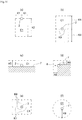
- FIG. 1 although not illustrated in the drawing, a plurality of fruit-bearing trees or crops are cultivated in a line along an up-down direction in the drawing, and a plurality of cultivated lines of fruits and crops are provided at intervals in a left-right direction in the drawing. Further, the plurality of wireless information tags 2 are arranged to overlap the plurality of cultivated lines, and each of the wireless information tags 2 is installed by using a space or the like between the fruit-bearing trees or crops.
- the automated vehicle 1 for example, working vehicles such as a spray working vehicle for spraying pesticides, fertilizers and herbicides, and a harvest working vehicle can be used. However, various working vehicles other than the above can also be applied.
- the automated vehicle 1 is provided with a travel portion 3 including a plurality of wheels, and a car body portion 4 supported by the travel portion 3.
- various devices such as a spraying device, are provided on the car body portion 4.
- various devices such as a harvesting device, are provided on the car body portion 4.
- the automated vehicle 1 is provided with a travel control portion 11 which controls traveling of the automated vehicle 1, a vehicle-side communication portion 12 which performs communication with the wireless information tag 2, a distance detecting portion 13 which detects a distance to the automated vehicle 1 relative to the wireless information tag 2 by communication between the wireless information tag 2 and the vehicle-side communication portion 12, an orientation detecting portion 14 which detects an orientation of the automated vehicle 1 relative to the wireless information tag 2 by communication between the wireless information tag 2 and the vehicle-side communication portion 12, and a vehicle-side storage portion 15 including a nonvolatile memory or the like storing various kinds of information.
- a relative position detecting portion is configured by including the distance detecting portion 13 and the orientation detecting portion 14.
- the travel control portion 11 controls the travel portion 3 such that the traveling direction of the automated vehicle 1 is set to a desired traveling direction, and the vehicle speed is set to a desired vehicle speed, for example.
- the vehicle-side communication portion 12 includes an antenna, a reader, a writer, etc., and wirelessly communicates with the wireless information tag 2 by using radio waves of a predetermined frequency.
- a phase of a signal received from the wireless information tag 2 during movement of the automated vehicle 1 a position of the automated vehicle 1 at a timing when the inclination of a change in the phase is inverted, and a travel distance of the automated vehicle 1, for example, are used.
- a distance to the automated vehicle 1 relative to the wireless information tag 2 and an orientation of the automated vehicle 1 relative to the wireless information tag 2 are calculated. Since the above methods of detection are well-known technique, as disclosed in, for example, Japanese Patent No. 5987187 , a detailed description thereof is omitted. Further, as the method of detecting a distance by the distance detecting portion 13, and the method of detecting an orientation by the orientation detecting portion 14, a detection method different from the well-known technique as disclosed in Japanese Patent No. 5987187 can be used.
- the wireless information tag 2 is provided with a tag-side communication portion 21 including an antenna, etc., for performing communication with the vehicle-side communication portion 12, and a tag-side storage portion 22 including a nonvolatile memory, etc., in which various kinds of information are stored.
- the wireless information tag 2 is configured as a passive type which operates on radio waves transmitted from the automated vehicle 1 as a source of energy, and does not have a battery.
- the communicable range of the wireless information tag 2 is, for example, within 3 to 5 meters.
- the plurality of wireless information tags 2 are used to identify a travel location where the automated vehicle 1 is made to travel automatically in the traveling region A.
- the arrangement positions of the plurality of wireless information tags 2 are set to positions corresponding to the travel location where the automated vehicle 1 is made to travel automatically.
- FIG. 1 exemplifies the travel location (traveling route) where the automated vehicle 1 is made to travel reciprocatingly, which is achieved by a travel mode of allowing the automated vehicle 1 to travel linearly from one end side to the other end side in the up-down direction, reversing the traveling direction by making the automated vehicle 1 turn at the other end side in the up-down direction, and allowing the automated vehicle 1 to travel linearly from the other end side to the one end side in the up-down direction, being executed repetitively.
- a travel mode of allowing the automated vehicle 1 to travel linearly from one end side to the other end side in the up-down direction, reversing the traveling direction by making the automated vehicle 1 turn at the other end side in the up-down direction, and allowing the automated vehicle 1 to travel linearly from the other end side to the one end side in the up-down direction, being executed repetitively.
- the arrangement positions of the plurality of wireless information tags 2 are set such that the wireless information tags 2 are aligned in the up-down direction in FIG. 1 .
- a support strut 5 extending in the vertical direction is disposed, as illustrated in FIG. 3 , for example, and the wireless information tag 2 is attached to a vertical intermediate portion of the support strut 5.
- the wireless information tag 2 is fixed to the support strut 5 by using a fixing tool such as a double-sided adhesive tape, and is attached to the support strut 5 in such a state of being prevented from wobbling or moving.
- the wireless information tag 2 may be attached to the predetermined position in such a way that an accommodation case or the like, in which the wireless information tag 2 can be embedded and accommodated, is fixed to the support strut in advance, and the wireless information tag 2 is embedded and accommodated in the accommodation case.
- the distance detecting portion 13 detects a distance to the automated vehicle 1 relative to the wireless information tag 2
- the orientation detecting portion 14 detects the orientation of the automated vehicle 1 relative to the wireless information tag 2.
- the travel control portion 11 can ascertain a relative position of the automated vehicle 1 with respect to the wireless information tag 2, on the basis of the distance to the automated vehicle 1 relative to the wireless information tag 2, which is detected by the distance detecting portion 13, and the orientation of the automated vehicle 1 relative to the wireless information tag 2, which is detected by the orientation detecting portion 14.
- the travel control portion 11 identifies the travel location of the automated vehicle 1 which has been set in advance, and controls the traveling of the automated vehicle 1 such that the automated vehicle 1 travels through the identified travel location.
- a method for identifying the travel location of the automated vehicle 1, the automatic traveling of the automated vehicle 1 at that time, and the like, will be described later.
- the plurality of wireless information tags 2 include wireless information tags 2a for travel location identification, which are arranged in a pair, at an interval in a horizontal direction (left-right direction in FIG. 1 ) with respect to the traveling direction (up-down direction in FIG. 1 ) of the automated vehicle 1, and a wireless information tag 2b for turning, which stores turn information J to make the automated vehicle 1 turn and travel.
- Left-and-right pairs of wireless information tags 2a for travel location identification are arranged in such a state that they are aligned to be spaced from each other at a first predetermined interval PI, in the traveling direction of the automated vehicle 1, to correspond to the travel location used to make the automated vehicle 1 travel from the one end side to the other end side or from the other end side to the one end side in the up-down direction in FIG. 1 .
- a value smaller than that of the communicable range of the wireless information tag 2 is set.
- the plurality of wireless information tags 2 are arranged such that the intervals between the left-and-right pairs of wireless information tags 2 are set to regular intervals also in the horizontal direction (left-right direction in FIG.
- wireless communication can be carried out between a total of four wireless information tags 2, i.e., each set of two wireless information tags 2 in at least the traveling direction and the left-right direction, and the vehicle-side communication portion 12 of the automated vehicle 1.
- the wireless information tag 2b for turning is arranged to correspond to a position where the automated vehicle 1 is to be turned.
- the automated vehicle 1 is turned at the one end side and the other end side in the up-down direction in the drawing.
- the wireless information tags 2 located at an upper edge portion and a lower edge portion in the up-down direction in the drawing correspond to the wireless information tags 2b for turning.
- the automated vehicle 1 is configured such that the travel control portion 11 can acquire the address information B and the travel disabled area information C by communication between the vehicle-side communication portion 12 and the tag-side communication portion 21.
- the address information B corresponds to information indicating the exact address of location regarding the arrangement position of the wireless information tag 2. For example, by assuming the arrangement position of the wireless information tag 2, which is located at the leftmost side and is at the lowermost side in FIG. 1 , as "Address 1-1", and applying two coordinates with the above wireless information tag 2 being treated as a reference address, the address information B can be represented by two numbers. For example, the arrangement position of the wireless information tag 2, which is the second wireless information tag from the left and is located at the lowermost side, is assumed as "Address 2-1". The address information B can be set such that the first number is increased as the arrangement position of the wireless information tag 2 draws near to the right.
- the arrangement position of the wireless information tag 2, which is located at the leftmost side and is the second wireless information tag from the bottom, is assumed as "Address 1-2".
- the address information B can be set such that the second number is increased as the arrangement position of the wireless information tag 2 draws near to the upper side. Therefore, the arrangement position of the wireless information tag 2, which is located at the rightmost side and is at the uppermost side, can be set to "Address 4-7".
- the address information B set as described above is stored in the tag-side storage portion 22 in each of the plurality of wireless information tags 2.
- the travel disabled area information C corresponds to information indicating an area where the automated vehicle 1 is not permitted to travel. For example, if the automated vehicle 1 comes too close to the wireless information tag 2, there is a risk that the automated vehicle 1 may come into contact with the crops or the wireless information tag 2. Thus, as illustrated in FIG. 10 , a range of area extending from the wireless information tag 2 by a predetermined distance is defined as a travel disabled area C1 (i.e., an area extending from the wireless information tag 2 to a dotted line in FIG. 10 ).
- FIG. 10 (a) illustrates a case where the wireless information tag 2 is arranged at an edge portion relative to the arrangement direction (up-down direction in FIG. 1 ) of the plurality of wireless information tags 2, such as in the case of the wireless information tag 2b for turning.
- FIG. 10 (b) illustrates a case where the wireless information tag 2 is arranged at an intermediate portion relative to the arrangement direction (up-down direction in FIG. 1 ) of the plurality of wireless information tags 2, such as in the case of the wireless information tag 2a for travel location identification.
- FIG. 10 (a) a case where the wireless information tag 2 is arranged at an upper edge portion relative to the arrangement direction (up-down direction in FIG. 1 ) of the plurality of wireless information tags 2 is illustrated.
- a range of area extending from the arrangement position of the wireless information tag 2 to both sides in the left-right direction by a first predetermined distance K1, and also extending from the arrangement position of the wireless information tag 2 to the lower side in the up-down direction by a second predetermined distance K2 is set as the travel disabled area C1.
- a range of area extending from the arrangement position of the wireless information tag 2 to both sides in the left-right direction by a third predetermined distance K3, and also extending from the arrangement position of the wireless information tag 2 to both sides in the up-down direction by a fourth predetermined distance K4 is set as the travel disabled area C1.
- FIG. 10 (c) illustrates a case where the wireless information tag 2 is arranged on, for example, a wall portion 7, although this is not illustrated in FIG. 1 .
- FIG. 10 (d) illustrates a case where the wireless information tag 2 is arranged at a corner portion 8 of the wall portion 7 or the like.
- a range of area extending from the wall portion 7 by a fifth predetermined distance K5 is set as the travel disabled area C1.
- a range of area extending from the wall portion 7 by a sixth predetermined distance K6 is set as the travel disabled area C1, and the travel disabled area C1, which is in a bent shape according to the shape of the corner portion 8, is set.
- the travel disabled area C1 is an area to be set with reference to the arrangement position of the wireless information tag 2, what area is set as the travel disabled area C1 can be changed as appropriate.
- a rectangular range of area extending from the arrangement position of the wireless information tag 2 to both sides in the left-right direction by a seventh predetermined distance K7, and also extending from the arrangement position of the wireless information tag 2 to both sides in the up-down direction by an eighth predetermined distance K can be set as the travel disabled area C1.
- a circular range of area in which a ninth predetermined distance K9 from the arrangement position of the wireless information tag 2 is the radius, with the arrangement position of the wireless information tag 2 being the center can be set as the travel disabled area C1.
- the address information B and the travel disabled area information C are set as described above. Therefore, when the automated vehicle 1 travels, by communication between the vehicle-side communication portion 12 and the tag-side communication portion 21, the travel control portion 11 acquires the address information B and the travel disabled area information C. Thereby, the travel control portion 11 controls the traveling of the automated vehicle 1 such that the automated vehicle 1 does not travel through the travel disabled area C1 while ascertaining the address information B of the wireless information tag 2 with which wireless communication is being performed.
- the travel control portion 11 acquires the address information B by communication between the vehicle-side communication portion 12 and the tag-side communication portion 21. Therefore, the travel control portion 11 understands with which wireless information tag 2, in terms of the address where the wireless information tag 2 is located, the communication is being performed. Thus, when there exists a wireless information tag 2 incapable of performing communication due to trouble or the like along the way during automatic traveling of the automated vehicle 1, the travel control portion 11 can identify the address of location of the wireless information tag 2 in question, and is enabled to specify which wireless information tag 2, among the plurality of wireless information tags 2, has the trouble. Moreover, when there exists a wireless information tag 2 incapable of performing communication due to trouble or the like along the way during automatic traveling of the automated vehicle 1, the travel control portion 11 causes, for example, the automatic traveling of the automated vehicle 1 to stop.
- the wireless information tags 2a for travel location identification are arranged in pairs in the left-right direction with respect to the traveling direction of the automated vehicle 1. Therefore, when the automated vehicle 1 travels, as well as the wireless communication being carried out between the vehicle-side communication portion 12 and the tag-side communication portion 21 of the wireless information tag 2a for travel location identification located on the left side, the wireless communication is carried out between the vehicle-side communication portion 12 and the tag-side communication portion 21 of the wireless information tag 2a for travel location identification located on the right side. Further, the wireless communication is carried out repeatedly between the vehicle-side communication portion 12 and the tag-side communication portion 21 each time a set period elapses. Although the set period can be set by time, the set period can alternatively be set using the conditions other than time, such as each time the automated vehicle 1 moves by a set distance.
- the distance detecting portion 13 detects a first distance L1 to the automated vehicle 1 relative to the wireless information tag 2a for travel location identification which is located on the left side, and a second distance L2 to the automated vehicle 1 relative to the wireless information tag 2a for travel location identification which is located on the right side, each time the set period elapses.
- the orientation detecting portion 14 detects the orientation of the automated vehicle 1 relative to the wireless information tag 2a for travel location identification which is located on the left side, and the orientation of the automated vehicle 1 relative to the wireless information tag 2a for travel location identification which is located on the right side, each time the set period elapses.
- the travel control portion 11 acknowledges the first distance L1 and the second distance L2 by way of the detection by the distance detecting portion 13, and also acknowledges the orientation of the automated vehicle 1 relative to the wireless information tags 2a for travel location identification on both left and right sides by way of the detection by the orientation detecting portion 14. Thereby, the travel control portion 11 ascertains a relative position of the automated vehicle 1 with respect to the wireless information tags 2a for travel location identification on both left and right sides.
- the travel location of the automated vehicle 1 is set in advance with reference to the arrangement positions of the wireless information tags 2a for travel location identification. For example, as illustrated by a dotted line in FIG. 4 , the travel location of the automated vehicle 1 is set to a linear travel location (traveling route) D, which passes through a center point E between the wireless information tag 2a for travel location identification which is located on the left side and the wireless information tag 2a for travel location identification which is located on the right side.
- the travel location of the automated vehicle 1 is set to an area other than the travel disabled area C1, which is set by the travel disabled area information C stored in each of the wireless information tags 2.
- the travel control portion 11 is in possession of setting information for the travel location of the automated vehicle 1 in advance, and controls the traveling of the automated vehicle 1 by using the setting information for the travel location of the automated vehicle 1.
- the travel control portion 11 is aware of the relative position of the automated vehicle 1 with respect to the wireless information tags 2a for travel location identification on both left and right sides. Therefore, by identifying the center point E from the relative position, the travel control portion 11 identifies the travel location (traveling route) D. By controlling the travel portion 3 in accordance with the relationship between the first distance L1 and the second distance L2 such that a difference in speed according to the aforementioned relationship is generated between the left and right wheels, the travel control portion 11 controls the traveling of the automated vehicle 1 so that the automated vehicle 1 travels through the travel location D.
- the relationship between the first distance L1 and the second distance L2 can be assumed as, for example, the ratio between the first distance L1 and the second distance L2 or a difference between the first distance L1 and the second distance L2.
- the travel control portion 11 controls the travel portion 3 such that a difference in speed according to the relationship between the first distance L1 and the second distance L2 is generated between the left and right wheels, with a mode of allowing the speed of the left wheel to be higher than the speed of the right wheel. Consequently, it is possible to have the automated vehicle 1 travel in such a way that it approximates the travel location D, and the automated vehicle 1 can be made to automatically travel through the travel location D.
- the distance detection by the distance detecting portion 13 and the orientation detection by the orientation detecting portion 14 are performed repeatedly each time the wireless communication between the vehicle-side communication portion 12 and the tag-side communication portion 21 is carried out after the elapse of the set period. Accordingly, even if the automated vehicle 1 deviates from the travel location D, the travel control portion 11 is to control the traveling of the automated vehicle 1 so that the automated vehicle 1 approximates the travel location D each time the set period elapses, and thus the automated vehicle 1 can be made to travel automatically through the travel location D.
- the travel portion 3 is controlled such that a difference in speed according to the relationship between the first distance L1 and the second distance L2 (for example, the ratio or difference between the first distance L1 and the second distance L2) is generated between the left and right wheels.
- various types of control can be applied as long as that control can adjust the traveling direction of the automated vehicle 1.
- the travel control portion 11 can control the travel portion 3 such that a torque difference according to the relationship between the first distance L1 and the second distance L2 is generated between the left and right wheels.
- the travel control portion 11 can control the steering angle of a steering wheel or the like provided to the automated vehicle 1 according to the relationship between the first distance L1 and the second distance L2.
- the travel location D passing through the center point E is exemplified.
- the travel location is between the wireless information tag 2a for travel location identification which is located on the left side and the wireless information tag 2a for travel location identification which is located on the right side, and is an area other than the travel disabled area C1, which is set by the travel disabled area information C stored in each of the wireless information tags 2, what location is set as the travel location can be changed as appropriate.
- the travel location of the automated vehicle 1 can be set to a travel location (traveling route) G passing through a deviation point F, which is deviated to approximate the wireless information tag 2a for travel location identification which is located more to the left side than the center point E.
- the travel control portion 11 is aware of the relative position of the automated vehicle 1 with respect to the wireless information tags 2a for travel location identification on both left and right sides. Therefore, by identifying the deviation point F from the relative position, the travel location G can be identified.
- the travel control portion 11 performs the following when the relative position of the automated vehicle 1 with respect to the wireless information tags 2a for travel location identification on both left and right sides reaches a point on a line connecting the arrangement positions of the wireless information tags 2a for travel location identification on both left and right sides. That is, by wireless communication between the tag-side communication portion 21 of each of the next coming wireless information tags 2a for travel location identification on both left and right sides in the traveling direction and the vehicle-side communication portion 12, the detection by the distance detecting portion 13 and the detection by the orientation detecting portion 14 are carried out, and the travel control portion 11 ascertains the relative position of the automated vehicle 1 with respect to the next coming wireless information tags 2a for travel location identification on both left and right sides in the traveling direction.
- the wireless information tags 2 are arranged at the first predetermined intervals P1 smaller than the communicable range of the wireless information tags 2. Therefore, when the relative position of the automated vehicle 1 reaches a point on a line connecting the arrangement positions of the wireless information tags 2a for travel location identification on both left and right sides, wireless communication between the tag-side communication portion 21 of each of the next coming wireless information tags 2a for travel location identification on both left and right sides in the traveling direction and the vehicle-side communication portion 12 is enabled.
- the travel control portion 11 identifies, from the relative position of the automated vehicle 1 which has been ascertained, the center point E between the next coming wireless information tags 2a for travel location identification on both left and right sides in the traveling direction, to identify the travel location D, and controls the traveling of the automated vehicle 1 such that the automated vehicle 1 travels through the identified travel location D.
- the travel control portion 11 switches the wireless information tags 2a for travel location identification for ascertaining the relative position of the automated vehicle 1 to the next coming wireless information tags 2a for travel location identification on both left and right sides in the traveling direction. By doing so, the travel control portion 11 controls the traveling of the automated vehicle 1 so that the automated vehicle 1 travels through the travel location D.
- the timing for switching the wireless information tags 2a for travel location identification for ascertaining the relative position of the automated vehicle 1 is not limited to the timing each time the relative position of the automated vehicle 1 reaches the point on the line connecting the arrangement positions of the wireless information tags 2a for travel location identification on both left and right sides. That is, various timings, such as a timing when the communication with the next wireless information tags 2a for travel location identification is enabled, are applicable.
- FIG. 4 illustrates an example in which the travel locations D and G of the linear shape passing through the center point E and the deviation point F are set as the travel locations of the automated vehicle 1.
- curved travel locations H and I can be set.
- the travel location to be set can be set to the travel location H or I passing through the center point E or the deviation point F between the wireless information tags 2a for travel location identification on both left and right sides. Since the control by the travel control portion 11 is the same as that in the case of performing the automatic traveling through the linear travel locations D and G, description thereof is omitted.
- the wireless information tag 2 located at the edge portion relative to the arrangement direction (up-down direction in FIG. 1 ) of the plurality of wireless information tags 2 is set as the wireless information tag 2b for turning.
- the turn information J is stored in the tag-side storage portion 22, as illustrated in FIG. 2 .
- the turn information J corresponds to information for enabling the automated vehicle 1 to turn and travel, and is information related to a travel location (traveling route) M and a turning radius N, etc., when the turning traveling is to be performed, as illustrated in FIG. 6 , for example.
- the travel location M is set to an area other than the travel disabled area C1, which is set by the travel disabled area information C stored in the wireless information tag 2b for turning.
- FIG. 6 illustrates an example in which the travel location M of an arc shape connecting the center point E, which is between the left and right wireless information tags 2b for turning, and the center point E, which is between the next pairing left and right wireless information tags 2b for turning, is set.
- the travel control portion 11 acquires the turn information J by wireless communication between the tag-side communication portion 21 of the wireless information tag 2b for turning and the vehicle-side communication portion 12.
- the travel control portion 11 employs the wireless communication between the tag-side communication portion 21 of the left and right wireless information tags 2b for turning and the vehicle-side communication portion 12.
- the distance detecting portion 13 detects a distance to the automated vehicle 1 relative to the left and right wireless information tags 2b for turning
- the orientation detecting portion 14 detects the orientation of the automated vehicle 1 relative to the left and right wireless information tags 2b for turning. In this way, the travel control portion 11 ascertains the relative position of the automated vehicle 1 with respect to the left and right wireless information tags 2b for turning.
- the travel control portion 11 identifies the center point E, which corresponds to a start point of the travel location M of the automated vehicle 1 included in the turn information J, and controls the traveling of the automated vehicle 1 such that the automated vehicle 1 passes through the center point E.
- the travel control portion 11 controls the travel portion 3 such that the automated vehicle 1 is made to turn and travel at the turning radius N included in the turn information J. Consequently, the travel control portion 11 controls the traveling of the automated vehicle 1 such that the traveling is performed through the travel location M of the automated vehicle 1, and performs the turning traveling of the automated vehicle 1.
- the travel control portion 11 finishes the turning traveling, and switches the control to the travel control that is realized by communication with the right and left wireless information tags 2a for travel location identification, as described above.
- the travel control portion 11 While it is possible for the travel control portion 11 to start the turning traveling directly when the relative position of the automated vehicle 1 reaches the center point E corresponding to the start point of the travel location M, it is also possible to start the turning traveling after stopping the automated vehicle 1 at the center point E for a while. In addition, while it is possible for the travel control portion 11 to switch the control to the travel control that is realized by communication with the wireless information tags 2a for travel location identification directly when the relative position of the automated vehicle 1 reaches the center point E corresponding to the start point of the travel location M, it is also possible to switch the control to the travel control that is realized by communication with the wireless information tags 2a for travel location identification after stopping the automated vehicle 1 at the center point E for a while.
- a pair of left and right wireless information tags 2 located at the edge portion relative to the arrangement direction of the plurality of wireless information tags 2 are employed as the wireless information tags 2b for turning.
- the wireless information tags 2b for turning it is possible to employ only the wireless information tag 2 that is located on the side for turning traveling (i.e., the right side in FIGS. 1 and 6 ), of the pair of left and right wireless information tags 2, as the wireless information tag 2b for turning, to make the automated vehicle 1 turn and travel.
- the travel control portion 11 makes the automated vehicle 1 travel automatically while identifying the travel location (traveling route) using the relative position of the automated vehicle 1 with respect to the wireless information tags 2, which is enabled by communication with the wireless information tags 2a for travel location identification, and communication with the wireless information tags 2b for turning.
- the automated vehicle 1 is made to automatically travel through the travel location D indicated by the dotted line, for example.
- the automated vehicle 1 travel reciprocatingly along a cultivated line where fruit-bearing trees and crops, which overlap the arrangement positions of the plurality of wireless information tags 2, are cultivated.
- spraying work of spraying fertilizers or the like at the places where the fruit-bearing trees and crops are cultivated, and the harvesting work for the fruit-bearing trees and crops, by the automated vehicle 1.
- the plurality of wireless information tags 2 include a wireless information tag 2c for obstacle in which a relative position of the obstacle Q with respect to the wireless information tag 2c is stored as obstacle information R (see FIG. 2 ), in addition to the wireless information tag 2a for travel location identification, and the wireless information tag 2b for turning.
- the wireless information tag 2 located at a position corresponding to the existing position of the obstacle Q is employed as the wireless information tag 2c for obstacle.
- two wireless information tags 2 that are located near the existing position of the obstacle Q are set as the wireless information tags 2c for obstacle.
- the existing position of the obstacle Q is located, for example, it is possible to change as appropriate which wireless information tag 2 is employed as the wireless information tag 2c for obstacle.
- the obstacle information R is stored in the tag-side storage portion 22. Further, as illustrated in FIG. 7 , the obstacle information R corresponds to information indicating the relative position of the obstacle Q with respect to the wireless information tag 2c for obstacle.
- the relative position of the obstacle Q with respect to the wireless information tag 2c for obstacle is represented by X-Y coordinates in which the wireless information tag 2c for obstacle is the reference point (zero point).
- the obstacle Q exists in an area surrounded by a first edge point S1 (x1, y1), a second edge point S2 (x2, y2), a third edge point S3 (x3, y3), and a fourth edge point S4 (x4, y4).
- the direction of the Y-coordinate conforms to the direction along the traveling direction of the automated vehicle 1
- the direction of the X-coordinate conforms to the left-right direction orthogonal to the traveling direction of the automated vehicle 1.
- the relative position of the obstacle Q with respect to the wireless information tag 2c for obstacle is indicated in a state where the directions of the X-Y coordinates correspond to the traveling direction of the automated vehicle 1.
- wireless communication is carried out between the vehicle-side communication portion 12 and the tag-side communication portion 21 of the wireless information tag 2a for travel location identification which is located on the left, and also, the wireless communication is carried out between the vehicle-side communication portion 12 and the tag-side communication portion 21 of the wireless information tag 2c for obstacle which is located on the right.
- the travel control portion 11 ascertains the relative position of the automated vehicle 1 with respect to the wireless information tag 2a for travel location identification, which is on the left, and the wireless information tag 2c for obstacle, which is on the right, on the basis of distance detection by the distance detecting portion 13, and orientation detection by the orientation detecting portion 14.
- the travel control portion 11 acquires the obstacle information R (see FIG. 7 ) stored in the wireless information tag 2c for obstacle. Therefore, the travel control portion 11 is also aware of the relative position of the obstacle Q with respect to the wireless information tag 2c for obstacle.
- the travel control portion 11 identifies a travel location (traveling route) U for avoiding the obstacle Q, on the basis of the relative position of the automated vehicle 1 with respect to the wireless information tag 2a for travel location identification, which is on the left, and the wireless information tag 2c for obstacle, which is on the right, and the relative position of the obstacle Q with respect to the wireless information tag 2c for obstacle. Further, the travel control portion 11 controls the traveling of the automated vehicle 1 such that the automated vehicle 1 travels through the identified travel location U.
- the travel location U for avoiding the obstacle Q the travel location U passing through a center point T between the left-side wireless information tag 2a for travel location identification and the third edge point S3 of the obstacle Q is set.
- the travel location U is the travel location for allowing the automated vehicle 1 to automatically travel continuously from the travel location D between the left-side wireless information tag 2a for travel location identification and the right-side wireless information tag 2c for obstacle.
- the travel location U causes the traveling to be performed by detouring to the left from the travel location D, for the presence of the obstacle Q, from a place near in the traveling direction as compared to the existing position of the obstacle Q.
- the wireless information tag 2c for obstacle may be arranged at a position corresponding to the existing position of the obstacle Q.
- the travel control portion 11 can acquire the obstacle information R (see FIG. 7 ) stored in the wireless information tag 2c for obstacle, and control the traveling of the automated vehicle 1 so as to avoid the obstacle Q.
- FIG. 7 illustrates the example in which the relative position of the obstacle Q with respect to the wireless information tag 2c for obstacle is represented by the X-Y coordinates with the wireless information tag 2c for obstacle being reference point (zero point).
- the form in which the obstacle information R is stored can be changed as appropriate.
- FIG. 9 it is possible to provide a field in which a plurality of dots V are arranged side by side at a constant predetermined interval W in the up-down direction and the left-right direction, and to indicate the existing position of the obstacle Q by the arrangement positions of the dots V on the field.
- an area surrounded by the arrangement positions of the dots V as indicated by oblique lines corresponds to the existing position of the obstacle Q.
- the up-down direction in FIG. 9 conforms to the direction along the traveling direction of the automated vehicle 1
- the left-right direction in FIG. 9 conforms to the left-right direction orthogonal to the traveling direction of the automated vehicle 1.
- the relative position of the obstacle Q with respect to the wireless information tag 2c for obstacle is indicated in a state where the arrangement directions of the plurality of dots V correspond to the traveling direction of the automated vehicle 1.
- the wireless information tag 2 a plurality of wireless information tags 2 such as the wireless information tag 2a for travel location identification, the wireless information tag 2b for turning, and the wireless information tag 2c for obstacle are exemplified. All of these wireless information tags 2a to 2c are the wireless information tags 2 having a similar configuration.
- the wireless information tag 2 is employed as one of the wireless information tag 2a for travel location identification, the wireless information tag 2b for turning, and the wireless information tag 2c for obstacle.
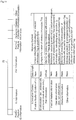
- FIG. 11 storage areas of the tag-side storage portion 22 are illustrated on the upper side, and a table indicating the information stored in each storage area is illustrated on the lower side.
- items of information which are position fixation ID information, ID information, pair information, position feature information, operation instruction information, obstacle information, and the other information, written to the wireless information tag 2 by a writer or the like, the items of information are stored in the predetermined storage areas, respectively, in the tag-side storage portion 22.
- the position fixation ID information is assumed as unique information indicating that the wireless information tag 2 is position-fixed, and this position fixation ID information is stored in the wireless information tag 2 of which the arrangement position is fixed.
- the ID information is unique information of the wireless information tag 2, and is assumed as information including the address information B and the travel disabled area information C.
- the ID information is stored in all of the plurality of wireless information tags 2.
- the pair information is assumed as information indicating the relationship with the wireless information tags 2 to be paired in the left-right direction with respect to the traveling direction of the automated vehicle 1, and the pair information is stored in the wireless information tag 2a for travel location identification.
- the position feature information is assumed as information indicating what kind of position the arrangement position of the wireless information tags 2 corresponds to.
- the position feature information is assumed as information which is one of information indicating that the position corresponds to the intermediate portion of a linear traveling route along which the automated vehicle 1 is made to travel, information indicating that the position corresponds to the edge portion of the linear traveling route along which the automated vehicle 1 is made to travel, and information indicating that the position corresponds to a corner of the traveling region A, in FIG. 1 , for example.
- the position feature information can be stored in all of the plurality of wireless information tags 2.
- the wireless information tag 2 storing the position feature information is assumed as the wireless information tag 2 for position feature. In the present embodiment, all of the wireless information tag 2a for travel location identification, the wireless information tag 2b for turning, and the wireless information tag 2c for obstacle can be employed as the wireless information tag 2 for position feature.
- the operation instruction information is assumed as information for instructing the automated vehicle 1 as to what operation to perform at the arrangement position of the wireless information tag 2.
- the operation position information is assumed as, for example, turn information for enabling the automated vehicle 1 to turn and travel, and information for stopping the automated vehicle 1.
- the obstacle information R is assumed as information indicating the relative position of the obstacle Q with respect to the wireless information tag 2, as illustrated in FIGS. 7 and 9 , and the obstacle information R is stored in the wireless information tag 2c for obstacle.
- the other information is assumed as information specific at the arrangement position of the wireless information tag 2, such as information on crops cultivated at the arrangement position of the wireless information tag 2. Deciding which wireless information tag 2 can be chosen to store the other information can be selected as appropriate.
- a single wireless information tag 2 can be configured as the wireless information tag 2a for travel location identification, the wireless information tag 2b for turning, or the wireless information tag 2c for obstacle. Also, a single wireless information tag 2 can be used as both the wireless information tag 2a for travel location identification and the wireless information tag 2c for obstacle, for example.
- the information stored in the tag-side storage portion 22 can be rewritten. Thus, for example, by rewriting the information stored in the tag-side storage portion 22, the wireless information tag can be changed from the wireless information tag 2a for travel location identification to the wireless information tag 2b for turning.
- the travel control portion 11 controls the traveling of the automated vehicle 1 such that the automated vehicle 1 travels forward while maintaining the traveling direction. Further, it is possible to cause the travel control portion 11 to change the traveling direction of the automated vehicle 1 only when there is a possibility that the automated vehicle 1 may enter the travel disabled area C1, so that the traveling of the automated vehicle 1 can be controlled to avoid the travel disabled area C1. By performing such control, it is possible to allow the automated vehicle 1 to travel forward in an area other than the travel disabled area C1 while preventing entry to the travel disabled area C1.
- the present invention can be applied to various automatic travel systems enabling the automated vehicle to travel automatically.
Landscapes
- Engineering & Computer Science (AREA)
- Physics & Mathematics (AREA)
- General Physics & Mathematics (AREA)
- Radar, Positioning & Navigation (AREA)
- Remote Sensing (AREA)
- Aviation & Aerospace Engineering (AREA)
- Life Sciences & Earth Sciences (AREA)
- Automation & Control Theory (AREA)
- Mechanical Engineering (AREA)
- Electromagnetism (AREA)
- Environmental Sciences (AREA)
- Soil Sciences (AREA)
- Control Of Position, Course, Altitude, Or Attitude Of Moving Bodies (AREA)
- Guiding Agricultural Machines (AREA)
- Position Fixing By Use Of Radio Waves (AREA)
Applications Claiming Priority (2)
| Application Number | Priority Date | Filing Date | Title |
|---|---|---|---|
| JP2018011542A JP6854249B2 (ja) | 2018-01-26 | 2018-01-26 | 自動走行システム |
| PCT/JP2018/040542 WO2019146202A1 (ja) | 2018-01-26 | 2018-10-31 | 自動走行システム |
Publications (2)
| Publication Number | Publication Date |
|---|---|
| EP3745232A1 true EP3745232A1 (de) | 2020-12-02 |
| EP3745232A4 EP3745232A4 (de) | 2021-12-15 |
Family
ID=67395394
Family Applications (1)
| Application Number | Title | Priority Date | Filing Date |
|---|---|---|---|
| EP18902412.8A Withdrawn EP3745232A4 (de) | 2018-01-26 | 2018-10-31 | Automatisches fahrsystem |
Country Status (3)
| Country | Link |
|---|---|
| EP (1) | EP3745232A4 (de) |
| JP (1) | JP6854249B2 (de) |
| WO (1) | WO2019146202A1 (de) |
Cited By (1)
| Publication number | Priority date | Publication date | Assignee | Title |
|---|---|---|---|---|
| EP4393284A4 (de) * | 2021-08-27 | 2025-09-24 | Kubota Kk | Arbeitsmaschine |
Families Citing this family (3)
| Publication number | Priority date | Publication date | Assignee | Title |
|---|---|---|---|---|
| JP7427144B1 (ja) * | 2022-10-03 | 2024-02-02 | フィブイントラロジスティクス株式会社 | 無人搬送車走行システム |
| WO2024075379A1 (ja) * | 2022-10-03 | 2024-04-11 | フィブイントラロジスティクス株式会社 | 無人搬送車走行システム |
| JP2025165740A (ja) * | 2024-04-23 | 2025-11-05 | 株式会社中嶋製作所 | 畜舎洗浄装置、畜舎洗浄方法、及び畜舎洗浄システム |
Family Cites Families (8)
| Publication number | Priority date | Publication date | Assignee | Title |
|---|---|---|---|---|
| JP3764713B2 (ja) * | 2002-09-13 | 2006-04-12 | 三菱重工業株式会社 | 保守点検システム及び保守点検方法 |
| JP2008092818A (ja) * | 2006-10-06 | 2008-04-24 | Yanmar Co Ltd | 農用作業車 |
| JP2009259023A (ja) * | 2008-04-17 | 2009-11-05 | Panasonic Corp | 自走式機器およびそのプログラム |
| CN101957447A (zh) * | 2009-07-16 | 2011-01-26 | 北京石油化工学院 | 基于有源rfid的室内移动机器人定位系统和方法 |
| JP2011076215A (ja) * | 2009-09-29 | 2011-04-14 | Nec Personal Products Co Ltd | 自動走行ルートガイドツールおよび自動走行装置 |
| CN104834313B (zh) * | 2015-05-15 | 2017-12-15 | 济南大学 | 一种基于rfid的大棚智能喷药机器人及方法 |
| JP5987187B1 (ja) * | 2015-10-16 | 2016-09-07 | Rfルーカス株式会社 | 記憶媒体位置検出システム及びプログラム |
| JP2017194764A (ja) * | 2016-04-19 | 2017-10-26 | 古屋製材株式会社 | 自動走行方法及びその方法を利用した自動走行運搬車並びに自動走行システム |
-
2018
- 2018-01-26 JP JP2018011542A patent/JP6854249B2/ja active Active
- 2018-10-31 EP EP18902412.8A patent/EP3745232A4/de not_active Withdrawn
- 2018-10-31 WO PCT/JP2018/040542 patent/WO2019146202A1/ja not_active Ceased
Cited By (1)
| Publication number | Priority date | Publication date | Assignee | Title |
|---|---|---|---|---|
| EP4393284A4 (de) * | 2021-08-27 | 2025-09-24 | Kubota Kk | Arbeitsmaschine |
Also Published As
| Publication number | Publication date |
|---|---|
| JP2019128882A (ja) | 2019-08-01 |
| WO2019146202A1 (ja) | 2019-08-01 |
| EP3745232A4 (de) | 2021-12-15 |
| JP6854249B2 (ja) | 2021-04-07 |
Similar Documents
| Publication | Publication Date | Title |
|---|---|---|
| EP3745232A1 (de) | Automatisches fahrsystem | |
| US9129251B2 (en) | Rail-mounted robotic inventory system | |
| JP6973393B2 (ja) | 移動体誘導システム、移動体、誘導装置およびコンピュータプログラム | |
| CN109416544B (zh) | 移动体引导系统、移动体、引导装置以及存储器 | |
| AU2004226935B2 (en) | Work site tracking system and method | |
| RU2578587C1 (ru) | Устройство и способ для возбуждения приемопередающей метки | |
| ES3015166T3 (en) | Anti-collision system and method for ground vehicles | |
| US20050021195A1 (en) | Dynamic object avoidance with automated guided vehicle | |
| US20110135189A1 (en) | Swarm intelligence-based mobile robot, method for controlling the same, and surveillance robot system | |
| EP3058524B1 (de) | Bewegliche plattform zur automatisierten inventarnahme | |
| WO1998035276A1 (en) | Navigation system for automatic guided vehicle | |
| AU2010319750A1 (en) | Coordination of vehicle movement in a field | |
| US20190087615A1 (en) | Movable reading apparatus with a plurality of antennas | |
| AU2017352853B2 (en) | Improvements to precision guidance system for agricultural vehicles | |
| JP7578543B2 (ja) | 自動走行方法、自動走行システム、及び自動走行プログラム | |
| CN110968090B (zh) | 具有防碰撞设备的自动导引车辆 | |
| EP4098116A1 (de) | Sprüharbeitsverfahren, sprüharbeitssystem und sprüharbeitsprogramm | |
| JP2019530104A (ja) | 在庫品管理システム、運送装置及び運送装置と運送対象物との結合方法 | |
| JP2006236132A (ja) | 自律移動ロボット | |
| KR102123111B1 (ko) | Rfid 리더 장치 및 서버 장치 | |
| CN112123328A (zh) | 人机协作控制方法和系统 | |
| ES2897906T3 (es) | Carro robotizado | |
| JP2022118825A (ja) | 自律移動システム、自律移動方法及び自律移動プログラム | |
| JP2007033119A (ja) | ずれ量検出装置 | |
| WO2020257948A1 (en) | System and method for optical localization |
Legal Events
| Date | Code | Title | Description |
|---|---|---|---|
| STAA | Information on the status of an ep patent application or granted ep patent |
Free format text: STATUS: THE INTERNATIONAL PUBLICATION HAS BEEN MADE |
|
| PUAI | Public reference made under article 153(3) epc to a published international application that has entered the european phase |
Free format text: ORIGINAL CODE: 0009012 |
|
| STAA | Information on the status of an ep patent application or granted ep patent |
Free format text: STATUS: REQUEST FOR EXAMINATION WAS MADE |
|
| 17P | Request for examination filed |
Effective date: 20200724 |
|
| AK | Designated contracting states |
Kind code of ref document: A1 Designated state(s): AL AT BE BG CH CY CZ DE DK EE ES FI FR GB GR HR HU IE IS IT LI LT LU LV MC MK MT NL NO PL PT RO RS SE SI SK SM TR |
|
| AX | Request for extension of the european patent |
Extension state: BA ME |
|
| DAV | Request for validation of the european patent (deleted) | ||
| DAX | Request for extension of the european patent (deleted) | ||
| RIC1 | Information provided on ipc code assigned before grant |
Ipc: G01S 5/14 20060101ALI20210805BHEP Ipc: A01B 69/00 20060101ALI20210805BHEP Ipc: G05D 1/02 20200101AFI20210805BHEP |
|
| A4 | Supplementary search report drawn up and despatched |
Effective date: 20211115 |
|
| RIC1 | Information provided on ipc code assigned before grant |
Ipc: G01S 5/14 20060101ALI20211109BHEP Ipc: A01B 69/00 20060101ALI20211109BHEP Ipc: G05D 1/02 20200101AFI20211109BHEP |
|
| STAA | Information on the status of an ep patent application or granted ep patent |
Free format text: STATUS: EXAMINATION IS IN PROGRESS |
|
| 17Q | First examination report despatched |
Effective date: 20220706 |
|
| STAA | Information on the status of an ep patent application or granted ep patent |
Free format text: STATUS: THE APPLICATION HAS BEEN WITHDRAWN |
|
| 18W | Application withdrawn |
Effective date: 20221028 |