EP3744919B1 - Verbesserter vorgefertigter leichtbalken zum bau von betonböden - Google Patents
Verbesserter vorgefertigter leichtbalken zum bau von betonböden Download PDFInfo
- Publication number
- EP3744919B1 EP3744919B1 EP19177226.8A EP19177226A EP3744919B1 EP 3744919 B1 EP3744919 B1 EP 3744919B1 EP 19177226 A EP19177226 A EP 19177226A EP 3744919 B1 EP3744919 B1 EP 3744919B1
- Authority
- EP
- European Patent Office
- Prior art keywords
- elongated
- anchoring plate
- channel
- joist
- opposing
- Prior art date
- Legal status (The legal status is an assumption and is not a legal conclusion. Google has not performed a legal analysis and makes no representation as to the accuracy of the status listed.)
- Active
Links
Images


Classifications
-
- E—FIXED CONSTRUCTIONS
- E04—BUILDING
- E04B—GENERAL BUILDING CONSTRUCTIONS; WALLS, e.g. PARTITIONS; ROOFS; FLOORS; CEILINGS; INSULATION OR OTHER PROTECTION OF BUILDINGS
- E04B5/00—Floors; Floor construction with regard to insulation; Connections specially adapted therefor
- E04B5/16—Load-carrying floor structures wholly or partly cast or similarly formed in situ
- E04B5/17—Floor structures partly formed in situ
- E04B5/18—Floor structures partly formed in situ with stiffening ribs or other beam-like formations wholly cast between filling members
- E04B5/19—Floor structures partly formed in situ with stiffening ribs or other beam-like formations wholly cast between filling members the filling members acting as self-supporting permanent forms
-
- E—FIXED CONSTRUCTIONS
- E04—BUILDING
- E04C—STRUCTURAL ELEMENTS; BUILDING MATERIALS
- E04C5/00—Reinforcing elements, e.g. for concrete; Auxiliary elements therefor
- E04C5/01—Reinforcing elements of metal, e.g. with non-structural coatings
- E04C5/06—Reinforcing elements of metal, e.g. with non-structural coatings of high bending resistance, i.e. of essentially three-dimensional [3D] extent, e.g. lattice girders
- E04C5/065—Light-weight girders, e.g. with precast parts
- E04C5/0653—Light-weight girders, e.g. with precast parts with precast parts
Definitions
- the present invention relates to a pre-fabricated lightweight joist for constructing concrete floors.
- the invention further relates to an intermediate structure and a concrete floor comprising the pre-fabricating lightweight joists.
- the invention further relates to a method for making the pre-fabricated lightweight joists.
- the manufacture of concrete floors for example spanning between multiple supporting walls of a construction such as a building, is known in the state of the art.
- the conventional method comprises as a first step providing a plurality of elongated joists extending in a longitudinal direction, each joist comprising an elongated channel having a substantially U-shaped cross-section delimited by a bottom wall and two opposing sidewalls, and an elongated lattice structure formed by an elongated upper bar connected by a truss to two elongated lower bars, wherein the two elongated lower bars are positioned within the elongated channel along the longitudinal direction.
- the plurality of joists are positioned parallel to each other on the supporting walls, for example with their longitudinal extremities, in particular with the longitudinal extremities of their elongated lattice structure, supported by opposing supporting walls.
- Vertical loads exerted onto the joists are supported by vertical load supporting means such as the opposing supporting walls and such as temporary shoring posts supporting the elongated channel at discrete positions along the longitudinal direction.
- a space is left between neighboring parallel joists, which space is subsequently bridged by positioning interjoist components such as hollow-core slabs in between two neighboring joists.
- the interjoist components are typically supported by free ends of the elongated channel sidewalls of two neighboring joists.
- the joists supported a.o.
- the weight exerted onto the interjoist components is securely supported by the vertical load supporting means via the elongated lattice structure, substantially independent of the vicinity of the vertical load supporting means to the position of vertical load application.
- the two elongated lower bars are mechanically anchored into the elongated channel by pre-filling the elongated channel with concrete such as to surround the two elongated lower bars with concrete, which after hardening forms a mechanically stable joist.
- pre-fabricate the joists for example at a factory, and to transport the pre-fabricated joists to the construction location were the concrete floor has to be constructed.
- Pre-fabricated joists are particularly desired in order to decrease construction times.
- Pre-fabricated joists wherein concrete is pre-filled in the elongated channel is however not practical, as the concrete substantially increases the weight of the pre-fabricated joists.
- These high-weight pre-fabricated joists are costly to transport from the factory to the construction location, and are particularly difficult to install, i.e. to lift the joists up to the position where it is supported by opposing supporting walls.
- clamping element in patent publication WO2016005679 is referred to as a ⁇ linking shim 5'. It has however been found in the present invention, that the intermediate structures formed by the light-weight pre-fabricated joists of the state of the art substantially lack mechanical stability.
- WO201301 9134 Another joist is for example known from WO201301 9134 which provides in an anchoring plate to secure an elongated lattice structure in an elongated channel.
- the anchoring plate has however been found cumbersome to use to secure the elongated lattice structure in the channel.
- WO2013019134 discloses a pre-fabricated lightweight joist according to the preamble of claim 1.
- the pre-fabricated lightweight joist for constructing concrete floors according to the present invention comprises an elongated channel for receiving concrete, wherein the elongated channel extends along a longitudinal direction.
- the elongated channel has a substantially U-shaped cross-section delimited by a bottom wall and two opposing sidewalls. Each of the walls of the elongated channel in particular extends along the longitudinal direction.
- the U-shaped cross-section is preferably taken along a plane perpendicular to the longitudinal direction.
- the joist further comprises an elongated lattice structure, in particular extending in the longitudinal direction.
- the lattice structure is formed by an elongated upper bar connected by a truss, for example a sinusoidal truss, to two elongated lower bars, for example forming a triangular structure in a plane perpendicular to the longitudinal direction.
- the lattice structure is preferably a metallic structure for example comprising steel.
- the two elongated lower bars are mechanically anchored within the elongated channel along the longitudinal direction.
- first anchoring means preferably comprising an elongated groove, i.e. elongated along the longitudinal direction.
- the joist further comprises at least one anchoring plate, for example arranged to engage the first anchoring means, preferably arranged to engage with the elongated grooves provided in the opposing sidewalls of the elongated channel.
- Each anchoring plate for example comprises second anchoring means complementary to the first anchoring means, the second anchoring means preferably comprising opposing first and second edges, forming protrusions suited to be inserted into the elongated grooves provided in the opposed sidewalls of the elongated channel.
- the two elongated lower bars of the elongated lattice are located within the elongated channel between the bottom wall of the elongated channel and the first anchoring means such as preferably the elongated grooves.
- the two elongated lower bars are mechanically anchored within the elongated channel by extending the at least one anchoring plate between the first anchoring means such as preferably the elongated grooves for example provided in the opposing sidewalls of the elongated channel, such that the at least one anchoring plate is provided between the two elongated lower bars and the elongated upper bar.
- the anchoring plate for example interconnects the opposing first anchoring means, for example interconnects the elongated grooves in the opposing sidewalls of the elongated channel.
- the joist of the present invention confers the desired mechanical stability to the resulting intermediate structure of joists and interjoist components, whilst limiting the weight of the joists thus enabling facilitated transport between the factory where the joists are pre-fabricated and the construction location, as well as enabling facilitated use of the pre-fabricated joists at the construction location such as facilitated mounting of the pre-fabricated joists onto the vertical load supporting means.
- the elongated channel sidewalls of the joists of the present invention when assembled into the intermediate structure comprising parallel joists and interjoist components supported on the free ends of the sidewalls of neighboring parallel joists, have a limited tendency to bend towards the loaded interjoist component, thus limiting the risk that the elongated lower bars are released from the elongated channels, thus limiting the risk of mechanical instability of the intermediate structure.
- the free ends of the sidewalls adjacent the loaded interjoist component are prevented from bending towards the interjoist component because the anchoring plate, being interconnected to both the opposing sidewalls of the elongated channel, acts as a spring countering the bending of the free end of the sidewall.
- the at least one anchoring plate provides additional security means, for example maintaining mechanical stability even when elongated lower bars are unintentionally released from the clamping elements.
- elongated channels of the light-weight pre-fabricated joists of the present invention are not required to be filled with a filling material such as concrete or polyurethane in order to confer the mechanical stability to the joists and intermediate structures.
- a filling material such as concrete or polyurethane
- the elongated channel can be filled with concrete in the final step of manufacturing the concrete floor, namely when concrete is poured over the intermediate structure.
- the concrete that surrounds the two elongated lower bars in the elongated channel is therefore substantially monolithic with the remaining concrete in the concrete floor such as the concrete provided over the interjoist components.
- Providing a monolithic concrete structure drastically increases the mechanical stability of the concrete floor with respect to concrete floors comprising pre-filled joists such as joists pre-filled with concrete or pre-filled with polyurethane.
- pre-filled joists such as joists pre-filled with concrete or pre-filled with polyurethane.
- an interface layer is present between the pre-filled material and the concrete that is poured during the final manufacturing step. It has been found that this interface layer is particularly prone to crack formation under excessive mechanical stress, for example upon bending of the joist due to vertical loads being applied to it. It has particularly been found that cracks tend to form at the interface layer when the concrete floor is subject to fire, due to amongst others the bending of the joists due to the thermal expansion of the lattice structure.
- the type and/or number of anchoring plates can be easily changed, for example increased, even after fabrication of the joists, for example until the pouring of the concrete in the last manufacturing step.
- an additional anchoring plate for example of a different type than the anchoring plates already attached to the elongated channel, can be easily attached to the first anchoring means of the elongated channel such as to the elongated grooves provided in the opposed elongated channel sidewalls.
- the attachment of an additional anchoring plate for example does not require the removal of the elongated lattice and/or the other anchoring plates, from the elongated channel.
- Changing the amount and/or type of anchoring plates can for example be performed at the construction location, for example in view of changed loading requirements for the joists.
- the at least one anchoring plate contacts the two elongated lower bars.
- a vertical load being applied to an interjoist component in the intermediate structure would push the channel downwards.
- the interconnected anchoring plates are pushed downwards due to the vertical load.
- the anchoring plates will be supported by the elongated lattice structure, thus preventing further downward movement of the channel.
- the elongated lattice structure thus efficiently transfers the vertical load to the vertical load supporting means.
- the elongated channel has a height direction, preferably perpendicular to the bottom wall i.e. when the bottom wall is flat.
- the elongated channel further has a width direction perpendicular to the longitudinal direction and the height direction, i.e. extending between the opposing sidewalls of the channel.
- the two elongated lower bars are mechanically anchored within the elongated channel by eliminating the translational degrees of freedom along the height direction, for example at least preventing the separation of the channel and the elongated lattice structure along the height direction.
- the elongated channel is provided with spacers fixed to the bottom wall, wherein the spacers hold the two elongated lower bars at an elevated position with respect to the bottom wall.
- Providing spacers enables the concrete to better surround the two elongated lower bars when pouring the concrete in the last step of manufacturing the concrete floor.
- the component referred to as ⁇ linking shim 5' in patent publication WO2016005679 can be provided as a spacer.
- the spacers are arranged to accommodate different types of lattice structures, i.e. as well lattice structures having elongated lower bars with large diameters and lattice structures having elongated lower bars with small diameters.
- the two elongated lower bars are mechanically anchored within the elongated channel by further eliminating the translational degrees of freedom along the width direction, preferably by providing the spacers engaging the elongated lower bars.
- the two elongated lower bars are mechanically anchored within the elongated channel by further eliminating all rotational degrees of freedom.
- the present embodiment is preferably obtained by providing at least two non-axially positioned spacers, i.e. by providing at least one spacer for each elongated lower bar.
- the first anchoring means preferably the elongated grooves such as the elongated groove provided in each sidewall, extend parallel to each other substantially in the longitudinal direction, preferably along substantially the entire length of the elongated channel, for example along the entire length of the elongated channel.
- Providing parallel first anchoring means facilitates the engagement with the anchoring plate.
- the first anchoring means are provided within the channel, i.e. not an a surface of the sidewall outside of the channel.
- the first anchoring means are provided adjacent to the sidewall free ends, thereby optimally preventing the bending of the sidewalls towards the adjacent loaded interjoist component.
- multiple anchoring plates are provided along the longitudinal direction.
- the multiple anchoring plates are separated from each other along the longitudinal direction such as to allow the pouring of concrete into the elongated channel in the final manufacturing step for making the concrete floors.
- the anchoring plate has a width extending between a first edge and an opposing second edge, a thickness extending between a first major surface and an opposing second major surface, and a depth extending between a third edge and an opposing fourth edge, wherein the width is bigger than the depth, and wherein the depth is bigger than the thickness.
- the second anchoring means are provided along the first and second edges of the anchoring plates.
- the first and second edges are the second anchoring means, i.e. form protrusions arranged to engage within the elongated grooves provided in the opposing channel sidewalls.
- the thickness of the anchoring plate, at least adjacent the first and second edges, is substantially equal, for example only slightly superior, to the height of the opening of the elongated grooves such that the anchoring plate can be securely press-fitted into the elongated grooves.
- the anchoring plate is movable between a first position wherein the second anchoring means provided on the anchoring plate engage the first anchoring means of the sidewalls, and a second position wherein the second anchoring means provided on the anchoring plate are disengaged from the first anchoring means of the sidewalls.
- the anchoring plate can be brought from the second position to the first position, as well as from the first position to the second position, i.e. the anchoring plate is releasably engaged to the channel.
- Providing releasably connected anchoring plates enables to easily adjust the spacing between the anchoring plates, for example performed at the construction location, for example in view of changed loading requirements for the joists.
- the anchoring plate is rotatable between a first position wherein the second anchoring means provided on the anchoring plate engage the first anchoring means of the sidewalls, and a second position wherein the second anchoring means provided on the anchoring plate are disengaged from the first anchoring means of the sidewalls.
- the anchoring plate is rotatable between a first position wherein the first edge and the second opposing edge of the anchoring plate engage the opposing elongated grooves of the sidewalls, and a second position wherein the first edge and the second opposing edge of the anchoring plate are disengaged from the opposing grooves of the sidewalls.
- the anchoring plate is bendable along its depth direction between a first position wherein the anchoring plate is substantially unbended such that second anchoring means provided on the anchoring plate engage the first anchoring means of the sidewalls, and a second position wherein the anchoring plate is substantially bended such that the second anchoring means provided on the anchoring plate are disengaged from the first anchoring means of the sidewalls.
- the anchoring plate is bendable along its depth direction between a first position wherein the anchoring plate is substantially unbended such that first edge and the second opposing edge of the anchoring plate engage the opposing elongated grooves of the sidewalls, and a second position wherein the anchoring plate is substantially bended such that the first edge and the second opposing edge of the anchoring plate is disengaged from the opposing grooves of the sidewalls.
- the first anchoring means are elongated grooves for example penetrating the sidewall in the width direction of the channel and extending along the longitudinal direction along the channel
- the perpendicular distance between the bottoms of the opposing elongated grooves defines an inter-groove width.
- the bottoms of the elongated grooves are for example the positions along the width direction where the groove stops.
- the inter-groove width is preferably substantially constant along the longitudinal direction of the channel.
- the width of the anchoring plate is preferably equal or superior to the inter-groove width.
- the width of the anchoring plate is preferably substantially equal, for example only slightly superior to the inter-groove width, such that such that the anchoring plate can be securely press-fitted into the elongated grooves.
- the anchoring plate is provided with a protrusion extending from at least one of, preferably both of, the major surfaces of the anchoring plate in the height direction of the anchoring plate, wherein the protrusion is provided with a tunnel extending in the depth direction of the anchoring plate, wherein the tunnel is configured to receive a third elongated lower bar.
- the third elongated lower bar is preferably a metallic bar and preferably extends substantially parallel to two elongated lower bars of the lattice structure.
- the third elongated lower bar is preferably inserted into the tunnels once all anchoring plates are attached to the channel.
- the anchoring plate is a substantially flat plate.
- the anchoring plate for example is not curved.
- the anchoring plate comprises substantially flat end sections proximate the first edge and opposing second edge, and a substantially flat middle section between the end sections, wherein the middle section forms a raised plateau with respect to the end sections, and wherein the middle section is arranged to contact the two elongated lower bars.
- the first and second end sections of the anchoring plate are symmetrically disposed to each other.
- the present embodiment has the particular advantage that one anchoring plate can be used for different types of lattice structures, i.e. for lattice structures having elongated lower bars with large diameters and small diameters.
- the anchoring plate By merely flipping over the anchoring plate, for example such that the major surface of the anchoring plate that previously faced the bottom wall of the channel is now facing towards the elongated upper bar, the distance between the raised plateau of the anchoring plate and the bottom wall can be adapted.
- the anchoring plate can for example be provided with the raised plateau bulging towards the bottom wall of the channel, such as to ensure that the anchoring plate engages and thus mechanically anchors the two elongated lower bars of the lattice structure.
- the anchoring plate can for example be flipped with the raised plateau bulging away from the bottom wall of the channel, such that the two elongated lower bars of the lattice structure to be placed between the anchoring plate and the bottom wall/or i.e. the spacers provided on the bottom wall.
- the elongated channel walls are made from a thermally insulating material, preferably a thermally insulating plastic material.
- the present embodiment has the advantage that the joist provides thermal insulation, without requiring to provide further insulation material such as polyurethane foam within the channel.
- the channel according to the present invention as opposed to conventional metallic channels, does not form a cold bridge.
- the present invention thus enables to create a monolithic concrete floor, due to the lack of pre-filling of the channel, whilst ensuring sufficient thermal insulation.
- the two elongated lower bars are substantially surrounded by air.
- the joists of the present invention are light-weight pre-fabricated joists, which are mechanically stable when assembled into an intermediate structure and which enable to provide a concrete floor where the concrete is substantially monolithic.
- the joist is provided with at least one supporting element at each of its longitudinal extremities.
- the supporting element is provided with a top surface on which the two elongated lower bars of the lattice structure rest.
- the supporting element is furthermore provided with a bottom surface resting on the supporting wall of the construction such as the building.
- the supporting element for example transfers vertical loads from the lattice structure onto the supporting wall of the construction, enabling to optimally release the channel from the vertical load transmission to the supporting wall.
- the supporting element is preferably attached to the lattice structure, for example by welding or clamping the supporting element to the two elongated lower bars.
- the joists are supported by vertical load supporting means such as opposing supporting walls of the construction and optionally temporary shoring posts.
- the intermediate structure is not yet provided with concrete. Concrete is poured in the last manufacturing step for creating the concrete floor.
- the two elongated lower bars in the intermediate structure are substantially surrounded by air.
- the concrete floor according to the present invention is a monolithic concrete structure, wherein no interface layer is present between the concrete provided in the channel and the concrete provided on the interjoist components.
- the method comprises the subsequent steps of:
- the step of mechanically anchoring the elongated lattice structure to the elongated channel comprises rotating the at least one anchoring plate from the second position to the first position.
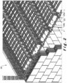
- FIG. 1 shows a perspective view of a joist 1 according to one embodiment of the present invention.
- the joist 1 is a pre-fabricated lightweight joist 1 for constructing concrete floors.
- the joist 1 comprises an elongated channel 2 for receiving concrete, the elongated channel 2 extending along a longitudinal direction, the elongated channel 2 having a substantially U-shaped cross-section delimited by a bottom wall 3 and two opposing sidewalls 4a, 4b.
- the elongated sidewalls 4a, 4b extend along a height direction from the bottom wall 3 up to a free end 24a, 24b.
- the free ends 24a, 24b of the sidewalls 4a, 4b are arranged for, in use, supporting interjoist components.
- the joist 1 further comprising an elongated metallic lattice structure 5 formed by an elongated upper bar 6 connected by a V-shaped truss, i.e. an armature, to two elongated lower bars 8a, 8b.
- Each one of the opposing sidewalls 4a, 4b of the elongated channel 2 is provided with a first anchoring means comprising an elongated groove 9a, 9b extending in the longitudinal direction adjacent to the free ends 24a, 24b of the sidewalls 4a, 4b.
- the joist 1 further comprises multiple anchoring plates 10 arranged to alleviate the separation of the channel 2 and the lattice structure 5 along the height direction.
- the two elongated lower bars 8a, 8b of the elongated lattice 5 are located within the elongated channel 2 between the bottom wall 3 of the elongated channel 2 and the elongated grooves 9a, 9b.
- the two elongated lower bars 8a, 8b are mechanically anchored within the elongated channel 2 by extending the multiple anchoring plates 10 between the elongated grooves 9a, 9b such that the multiple anchoring plates 10 are provided between the two elongated lower bars 8a, 8b and the elongated upper bar 6.
- the two elongated lower bars 8a, 8b are raised with respect to the bottom wall 3 of the channel 2 by a set of spacers 11.
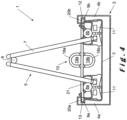
- Figure 2 shows a perspective view of an intermediate structure 22 according to one embodiment of the present invention.
- the intermediate structure 22 comprises multiple two pre-fabricated lightweight joists 1 such as the joists 1 presented in figure 1 .
- Multiple interjoist component 23 are supported by the sidewall free ends 24a, 24b of the elongated channels 2 of neighboring joists 1.
- the joists 1 are supported on opposing supporting walls of the construction, for example of the building.
- a concrete floor can be formed by pouring concrete onto the intermediate structure 22.
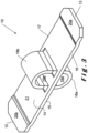
- FIG 3 shows a perspective view of an anchoring plate 10 according to one embodiment of the present invention, for example as used in the joists 1 of figure 1 or 2 .
- the anchoring plate 10 has a width extending between a first edge 12 and an opposing second edge 13, a thickness extending between a first major surface 14 and an opposing second major surface 15, and a depth extending between a third edge 16 and an opposing fourth edge 17. The width is bigger than the depth, and the depth is bigger than the thickness.
- the first and second edges 12, 13 are the second anchoring means, i.e. form protrusions arranged to engage within the elongated grooves 9a, 9b provided in the opposing channel sidewalls 4a, 4b.
- the anchoring plate 10 is provided with two protrusions 18a, 18b each one extending from the major surfaces 14, 15 of the anchoring plate in the height direction of the anchoring plate 10. Each protrusion 18a, 18b is provided with a tunnel 19a, 19b extending in the depth direction of the anchoring plate 10.
- the tunnel 19a, 19b is configured to receive a third elongated metallic lower bar.
- the anchoring plate 10 comprises substantially flat end sections 20b, 20a proximate the first edge 12 and opposing second edge 13, and a substantially flat middle section 21 between the end sections 20a, 20b.
- the middle section 21 forms a raised plateau with respect to the end sections 20a, 20b.
- the middle section 21 is arranged to contact the two elongated lower bars 8a, 8b.
- the present embodiment has the particular advantage that one anchoring plate 10 can be used for different types of lattice structures 5, i.e. for lattice structures 5 having elongated lower bars 8a, 8b with large diameters and small diameters as respectively shown in figures 4 and 5 .
- the anchoring plate 10 By merely flipping over the anchoring plate 10, for example such that the major surface 15 of the anchoring plate 10 that previously faced the bottom wall 3 of the channel 2 is now facing towards the elongated upper bar 6, the distance between the anchoring plate 10 and the bottom wall 3 can be adapted.
- the anchoring plate 10 can for example be provided with the raised plateau 21 bulging towards the bottom wall 3 of the channel 2, such as to ensure that the anchoring plate 10 engages and thus mechanically anchors the two elongated lower bars 8a, 8b of the lattice structure 5.
- the anchoring plate 10 can for example be flipped with the raised plateau 21 bulging away from the bottom wall 3 of the channel 2, such that the two elongated lower bars 8a, 8b of the lattice structure 5 can be placed between the anchoring plate 10 and the spacers 11 provided on the bottom wall 3.
Landscapes
- Engineering & Computer Science (AREA)
- Architecture (AREA)
- Civil Engineering (AREA)
- Structural Engineering (AREA)
- Physics & Mathematics (AREA)
- Electromagnetism (AREA)
- Floor Finish (AREA)
- Reinforcement Elements For Buildings (AREA)
- Rod-Shaped Construction Members (AREA)
Claims (12)
- Ein vorgefertigter Leichtbalken (1) zum Bau von Betonböden, wobei der Balken (1) einen länglichen Kanal (2) zum Aufnehmen von Beton umfasst, wobei sich der längliche Kanal (2) entlang einer Längsrichtung erstreckt, wobei der längliche Kanal (2) einen im Wesentlichen U-förmigen Querschnitt hat, begrenzt durch eine untere Wand (3) und zwei gegenüberliegende Seitenwände (4a, 4b), wobei der Balken (1) ferner einen länglichen Gitteraufbau (5) umfasst, geformt durch eine längliche obere Stange (6), verbunden durch einen Stab (7) mit zwei länglichen unteren Stangen (8a, 8b), wobei die zwei länglichen unteren Stangen (8a, 8b) mechanisch im länglichen Kanal (2) entlang der Längsrichtung verankert sind, wobei jede der gegenüberliegenden Seitenwände (4a, 4b) des länglichen Kanals (2) mit einer länglichen Nut (9a, 9b) versehen ist, wobei der Balken (1) ferner zumindest eine Verankerungsplatte (10) umfasst, wobei sich die zwei länglichen unteren Stangen (8a, 8b) des länglichen Gitters (5) innerhalb des länglichen Kanals (2) zwischen der unteren Wand (3) des länglichen Kanals (2) und den länglichen Nuten (9a, 9b) befinden, und wobei die zwei länglichen unteren Stangen (8a, 8b) durch Verlängern der zumindest eine Verankerungsplatte (10) zwischen den länglichen Nuten (9a, 9b) mechanisch so im länglichen Kanal (2) verankert sind, dass die zumindest eine Verankerungsplatte (10) zwischen den zwei länglichen unteren Stangen (8a, 8b) und der länglichen oberen Stange (6) bereitgestellt ist, wobei die Verankerungsplatte (10) eine Breite hat, welche sich zwischen einer ersten Kante (12) und einer gegenüberliegenden zweiten Kante (13) erstreckt, eine Dicke, welche sich zwischen einer ersten Hauptfläche (14) und einer gegenüberliegenden zweiten Hauptfläche (15) erstreckt, und eine Tiefe, welche sich zwischen einer dritten Kante (16) und einer gegenüberliegenden vierten Kante (17) erstreckt, wobei die Breite größer ist als die Tiefe, und wobei die Tiefe größer ist als die Dicke, dadurch gekennzeichnet, dass die Verankerungsplatte (10) drehbar zwischen einer ersten Position, in der die erste Kante (12) und die zweite gegenüberliegende Kante (13) der Verankerungsplatte (10) in die gegenüberliegenden länglichen Nuten (9a, 9b) der Seitenwände (4a, 4b) eingreifen, und einer zweiten Position, in der die erste Kante (12) und die zweite gegenüberliegende Kante (13) der Verankerungsplatte (10) von den gegenüberliegenden Nuten (9a, 9b) der Seitenwände (4a, 4b) ausgerückt sind.
- Der vorgefertigte Leichtbalken (1) nach dem vorigen Anspruch, wobei die zumindest eine Verankerungsplatte (10) die zwei länglichen unteren Stangen (8a, 8b) berührt.
- Der vorgefertigte Leichtbalken (1) nach dem vorigen Anspruch, wobei der längliche Kanal (2) eine Höhenrichtung und eine Breitenrichtung senkrecht zur Längsrichtung und der Höhenrichtung hat, wobei die zwei länglichen unteren Stangen (8a, 8b) mechanisch im länglichen Kanal (2) verankert sind, indem die translatorischen Freiheitsgrade entlang der Höhenrichtung unterbunden sind.
- Der vorgefertigte Leichtbalken (1) nach dem vorigen Anspruch, wobei der längliche Kanal (2) mit Abstandhaltern (11) versehen ist, befestigt an der unteren Wand (3), wobei die Abstandhalter (11) die zwei länglichen unteren Stangen (8a, 8b) in einer erhobenen Position in Bezug auf die untere Wand (3) halten.
- Der vorgefertigte Leichtbalken (1) nach irgendeinem der vorigen Ansprüche, wobei die länglichen Nuten (9a, 9b) im Wesentlichen in der Längsrichtung, bevorzugt entlang im Wesentlichen der gesamten Länge des länglichen Kanals (2), parallel zueinander verlaufen.
- Der vorgefertigte Leichtbalken (1) nach irgendeinem der vorigen Ansprüche, wobei der senkrechte Abstand zwischen den Böden der gegenüberliegenden länglichen Nuten (9a, 9b) eine Zwischennutbreite definiert, wobei die Zwischennutbreite entlang der Längsrichtung im Wesentlichen konstant ist, und wobei die Breite der Verankerungsplatte (10) gleich oder größer als die Zwischennutbreite ist.
- Der vorgefertigte Leichtbalken (1) nach irgendeinem der vorigen Ansprüche, wobei die Verankerungsplatte (10) mit eine Ausbuchtung (18a, 18b) versehen ist, welche sich von zumindest einer der Hauptflächen (14, 15) der Verankerungsplatte (10) in die Höhenrichtung der Verankerungsplatte (10) erstreckt, wobei die Ausbuchtung (18a, 18b) mit einem Tunnel (19a, 19b) versehen ist, welcher sich in die Tiefenrichtung der Verankerungsplatte (10) erstreckt, wobei der Tunnel (19a, 19b) konfiguriert ist, um eine dritte längliche untere Stange aufzunehmen.
- Der vorgefertigte Leichtbalken (1) nach irgendeinem der vorigen Ansprüche, wobei die Verankerungsplatte (10) im Wesentliche flache Endabschnitte (20a, 20b) nahe der ersten Kante (12) und der gegenüberliegenden zweiten Kante (13), und einen im Wesentlichen flachen Mittelabschnitt (21) zwischen den Endabschnitten (20a, 20b) umfasst, wobei der Mittelabschnitt (21) ein erhobenes Plateau in Bezug auf die Endabschnitte (20a, 20b) formt, und wobei der Mittelabschnitt (21) angeordnet ist, um die zwei länglichen unteren Stangen (8a, 8b) zu berühren.
- Der vorgefertigte Leichtbalken (1) nach irgendeinem der vorigen Ansprüche, wobei die Wände (3, 4a, 4b) des länglichen Kanals (2) aus einem thermisch isolierenden Material hergestellt sind, bevorzugt einem thermisch isolierenden Kunststoffmaterial.
- Eine Zwischenstruktur (22), welche zumindest zwei vorgefertigte Leichtbalken (1) nach irgendeinem der vorigen Ansprüche umfasst, wobei eine Zwischenbalkenkomponente (23) durch die seitenwandfreien Enden (24a, 24b) der länglichen Kanäle (2) nebeneinander liegender Balken (1) getragen wird.
- Ein Betonboden, welcher zumindest zwei vorgefertigte Leichtbalken (1) nach irgendeinem der vorigen Ansprüche 1 bis 99 umfasst, wobei eine Zwischenbalkenkomponente (23) durch die seitenwandfreien Enden (24a, 24b) der länglichen Kanäle (2) nebeneinander liegender Balken (1) getragen wird, wobei Beton so auf die Balken (1) und die Zwischenbalkenkomponente (23) gegossen wurde, dass er die länglichen Stangen (6, 8a, 8b) der Gitter (5) jedes Balkens (1) im Wesentlichen umgibt.
- Verfahren zur Herstellung vorgefertigter Leichtbalken (1) nach irgendeinem der vorigen Ansprüche 1 bis 919, wobei das Verfahren die folgenden, aufeinanderfolgenden Schritte umfasst:• Bereitstellen des länglichen Kanals (2), des länglichen Gitteraufbaus (5) und der zumindest einen Verankerungsplatte (10),• Platzieren der zwei länglichen unteren Stangen (8a, 8b) des länglichen Gitteraufbaus (5) zwischen der unteren Wand (3) des länglichen Kanals (2) und den länglichen Nuten (9a, 9b),• mechanisches Verankern des länglichen Gitteraufbaus (5) mit dem länglichen Kanal (2) durch Einführen der Verankerungsplatte (10) in die länglichen Nuten (9a, 9b), sodass sich die Verankerungsplatte (10) zwischen den länglichen Nuten (9a, 9b) erstreckt,wobei der Schritt des mechanischen Verankern des länglichen Gitteraufbaus (5) mit dem länglichen Kanal (2) das Drehen der zumindest einen Verankerungsplatte (10) von der zweiten Position in die erste Position umfasst.
Priority Applications (3)
| Application Number | Priority Date | Filing Date | Title |
|---|---|---|---|
| EP19177226.8A EP3744919B1 (de) | 2019-05-29 | 2019-05-29 | Verbesserter vorgefertigter leichtbalken zum bau von betonböden |
| FR2005591A FR3096701B1 (fr) | 2019-05-29 | 2020-05-27 | Poutrelle légère préfabriquée améliorée pour la construction de planchers en béton |
| BE20205368A BE1027279B1 (fr) | 2019-05-29 | 2020-05-27 | Poutrelle légère préfabriquée améliorée pour la construction de planchers en béton |
Applications Claiming Priority (1)
| Application Number | Priority Date | Filing Date | Title |
|---|---|---|---|
| EP19177226.8A EP3744919B1 (de) | 2019-05-29 | 2019-05-29 | Verbesserter vorgefertigter leichtbalken zum bau von betonböden |
Publications (3)
| Publication Number | Publication Date |
|---|---|
| EP3744919A1 EP3744919A1 (de) | 2020-12-02 |
| EP3744919B1 true EP3744919B1 (de) | 2024-08-21 |
| EP3744919C0 EP3744919C0 (de) | 2024-08-21 |
Family
ID=66676341
Family Applications (1)
| Application Number | Title | Priority Date | Filing Date |
|---|---|---|---|
| EP19177226.8A Active EP3744919B1 (de) | 2019-05-29 | 2019-05-29 | Verbesserter vorgefertigter leichtbalken zum bau von betonböden |
Country Status (3)
| Country | Link |
|---|---|
| EP (1) | EP3744919B1 (de) |
| BE (1) | BE1027279B1 (de) |
| FR (1) | FR3096701B1 (de) |
Family Cites Families (4)
| Publication number | Priority date | Publication date | Assignee | Title |
|---|---|---|---|---|
| DE896999C (de) * | 1951-08-25 | 1953-11-16 | Betonwerke Mutter & Schuessler | Gittertraeger als Bewehrung einer Stahlbetonrippendecke |
| FR2918087B3 (fr) * | 2007-06-28 | 2012-01-27 | Daniel Fovet | Poutrelle auto-portante et isolante de plancher ou toiture |
| RS54106B1 (sr) * | 2011-08-03 | 2015-10-30 | Milan KEKANOVIĆ | Postupak izgradnje objekata od montažno-monolitnih zidova i međuspratnih ploča |
| FR3023312B1 (fr) | 2014-07-07 | 2017-11-03 | Isoltop | Poutrelle pour la realisation d'un plancher |
-
2019
- 2019-05-29 EP EP19177226.8A patent/EP3744919B1/de active Active
-
2020
- 2020-05-27 FR FR2005591A patent/FR3096701B1/fr active Active
- 2020-05-27 BE BE20205368A patent/BE1027279B1/fr active IP Right Grant
Also Published As
| Publication number | Publication date |
|---|---|
| EP3744919A1 (de) | 2020-12-02 |
| BE1027279A1 (fr) | 2020-12-08 |
| FR3096701A1 (fr) | 2020-12-04 |
| BE1027279B1 (fr) | 2021-04-20 |
| EP3744919C0 (de) | 2024-08-21 |
| FR3096701B1 (fr) | 2022-05-13 |
Similar Documents
| Publication | Publication Date | Title |
|---|---|---|
| US8418422B2 (en) | Wall anchoring device and method | |
| US4702053A (en) | Composite insulated wall | |
| EP0996795B1 (de) | Säule aus verbundstahl-beton | |
| EP2522788A2 (de) | Lasttransportvorrichtung | |
| US20100065716A1 (en) | Device for anchoring concrete to an insulating panel and form employing device | |
| EP2966235A1 (de) | Baustein für wandkonstruktion | |
| KR102177975B1 (ko) | 데크플레이트를 이용한 보 거푸집 시스템 및 보 거푸집 제작설치방법 | |
| KR101783460B1 (ko) | 조립식 보강벽돌 | |
| JP6343277B2 (ja) | 鉄筋コンクリート床を構築するための焼結した発泡ポリスチレンの組み立て式要素 | |
| US20110247291A1 (en) | Reinforcement Bar Support Device | |
| WO2019027618A1 (en) | CONCRETE BUILDING ELEMENTS AND ASSOCIATED ASSEMBLIES, AND ASSOCIATED METHODS | |
| KR20170108215A (ko) | 아이 형강 하프피씨 바닥판 및 이의 제작 방법 그리고 그 시공방법 | |
| EP3744919B1 (de) | Verbesserter vorgefertigter leichtbalken zum bau von betonböden | |
| KR20190135876A (ko) | 오메가 수평근과 줄눈 록킹재를 통한 벽돌 벽체 내진보강 장치 및 이를 이용한 벽돌 벽체의 시공 방법 | |
| KR101304335B1 (ko) | 절곡성형부재를 구비한 프리캐스트 콘크리트 합성슬래브 및 그 시공 방법 | |
| KR102148250B1 (ko) | 수평형 압축 보강재 삽입형 하이브리드 단열판 및 이를 이용한 기초구조 | |
| KR101383817B1 (ko) | 역타공법 | |
| EP2260158A2 (de) | Platte zur konstruktion einer biegeresistenten struktur und verfahren zu konstruktion einer derartigen struktur | |
| CN213952451U (zh) | 一种预制池壁单元构件及装配式池塘 | |
| KR101677233B1 (ko) | 천정 벽돌과 이를 적용한 건축물의 천정 구조물 및 그 시공 방법 | |
| EP2397619A1 (de) | System aus selbsttragenden Mauerwerkswänden und Bauverfahren | |
| EP4491819A1 (de) | Baustein | |
| GB2552437A (en) | Shuttering system | |
| EP4108846B1 (de) | Verwendung zweier vorrichtungen um bauelemente miteinander zu verbinden und resultierende anordnung | |
| KR102112282B1 (ko) | 벽돌 세트 및 그것을 이용해 시공된 벽체 구조 |
Legal Events
| Date | Code | Title | Description |
|---|---|---|---|
| PUAI | Public reference made under article 153(3) epc to a published international application that has entered the european phase |
Free format text: ORIGINAL CODE: 0009012 |
|
| STAA | Information on the status of an ep patent application or granted ep patent |
Free format text: STATUS: THE APPLICATION HAS BEEN PUBLISHED |
|
| AK | Designated contracting states |
Kind code of ref document: A1 Designated state(s): AL AT BE BG CH CY CZ DE DK EE ES FI FR GB GR HR HU IE IS IT LI LT LU LV MC MK MT NL NO PL PT RO RS SE SI SK SM TR |
|
| AX | Request for extension of the european patent |
Extension state: BA ME |
|
| STAA | Information on the status of an ep patent application or granted ep patent |
Free format text: STATUS: REQUEST FOR EXAMINATION WAS MADE |
|
| 17P | Request for examination filed |
Effective date: 20210602 |
|
| RBV | Designated contracting states (corrected) |
Designated state(s): AL AT BE BG CH CY CZ DE DK EE ES FI FR GB GR HR HU IE IS IT LI LT LU LV MC MK MT NL NO PL PT RO RS SE SI SK SM TR |
|
| STAA | Information on the status of an ep patent application or granted ep patent |
Free format text: STATUS: EXAMINATION IS IN PROGRESS |
|
| 17Q | First examination report despatched |
Effective date: 20230123 |
|
| GRAP | Despatch of communication of intention to grant a patent |
Free format text: ORIGINAL CODE: EPIDOSNIGR1 |
|
| STAA | Information on the status of an ep patent application or granted ep patent |
Free format text: STATUS: GRANT OF PATENT IS INTENDED |
|
| INTG | Intention to grant announced |
Effective date: 20240313 |
|
| GRAS | Grant fee paid |
Free format text: ORIGINAL CODE: EPIDOSNIGR3 |
|
| GRAA | (expected) grant |
Free format text: ORIGINAL CODE: 0009210 |
|
| STAA | Information on the status of an ep patent application or granted ep patent |
Free format text: STATUS: THE PATENT HAS BEEN GRANTED |
|
| AK | Designated contracting states |
Kind code of ref document: B1 Designated state(s): AL AT BE BG CH CY CZ DE DK EE ES FI FR GB GR HR HU IE IS IT LI LT LU LV MC MK MT NL NO PL PT RO RS SE SI SK SM TR |
|
| REG | Reference to a national code |
Ref country code: GB Ref legal event code: FG4D |
|
| RIN1 | Information on inventor provided before grant (corrected) |
Inventor name: BERGHMAN, KOENRAAD Inventor name: COSNIER, BERNARD |
|
| REG | Reference to a national code |
Ref country code: CH Ref legal event code: EP |
|
| REG | Reference to a national code |
Ref country code: IE Ref legal event code: FG4D |
|
| REG | Reference to a national code |
Ref country code: DE Ref legal event code: R096 Ref document number: 602019057278 Country of ref document: DE |
|
| U01 | Request for unitary effect filed |
Effective date: 20240919 |
|
| U07 | Unitary effect registered |
Designated state(s): AT BE BG DE DK EE FI FR IT LT LU LV MT NL PT RO SE SI Effective date: 20241010 |
|
| PG25 | Lapsed in a contracting state [announced via postgrant information from national office to epo] |
Ref country code: NO Free format text: LAPSE BECAUSE OF FAILURE TO SUBMIT A TRANSLATION OF THE DESCRIPTION OR TO PAY THE FEE WITHIN THE PRESCRIBED TIME-LIMIT Effective date: 20241121 |
|
| PG25 | Lapsed in a contracting state [announced via postgrant information from national office to epo] |
Ref country code: GR Free format text: LAPSE BECAUSE OF FAILURE TO SUBMIT A TRANSLATION OF THE DESCRIPTION OR TO PAY THE FEE WITHIN THE PRESCRIBED TIME-LIMIT Effective date: 20241122 Ref country code: PL Free format text: LAPSE BECAUSE OF FAILURE TO SUBMIT A TRANSLATION OF THE DESCRIPTION OR TO PAY THE FEE WITHIN THE PRESCRIBED TIME-LIMIT Effective date: 20240821 |
|
| PG25 | Lapsed in a contracting state [announced via postgrant information from national office to epo] |
Ref country code: IS Free format text: LAPSE BECAUSE OF FAILURE TO SUBMIT A TRANSLATION OF THE DESCRIPTION OR TO PAY THE FEE WITHIN THE PRESCRIBED TIME-LIMIT Effective date: 20241221 |
|
| PG25 | Lapsed in a contracting state [announced via postgrant information from national office to epo] |
Ref country code: HR Free format text: LAPSE BECAUSE OF FAILURE TO SUBMIT A TRANSLATION OF THE DESCRIPTION OR TO PAY THE FEE WITHIN THE PRESCRIBED TIME-LIMIT Effective date: 20240821 |
|
| PG25 | Lapsed in a contracting state [announced via postgrant information from national office to epo] |
Ref country code: ES Free format text: LAPSE BECAUSE OF FAILURE TO SUBMIT A TRANSLATION OF THE DESCRIPTION OR TO PAY THE FEE WITHIN THE PRESCRIBED TIME-LIMIT Effective date: 20240821 Ref country code: RS Free format text: LAPSE BECAUSE OF FAILURE TO SUBMIT A TRANSLATION OF THE DESCRIPTION OR TO PAY THE FEE WITHIN THE PRESCRIBED TIME-LIMIT Effective date: 20241121 |
|
| PG25 | Lapsed in a contracting state [announced via postgrant information from national office to epo] |
Ref country code: RS Free format text: LAPSE BECAUSE OF FAILURE TO SUBMIT A TRANSLATION OF THE DESCRIPTION OR TO PAY THE FEE WITHIN THE PRESCRIBED TIME-LIMIT Effective date: 20241121 Ref country code: PL Free format text: LAPSE BECAUSE OF FAILURE TO SUBMIT A TRANSLATION OF THE DESCRIPTION OR TO PAY THE FEE WITHIN THE PRESCRIBED TIME-LIMIT Effective date: 20240821 Ref country code: NO Free format text: LAPSE BECAUSE OF FAILURE TO SUBMIT A TRANSLATION OF THE DESCRIPTION OR TO PAY THE FEE WITHIN THE PRESCRIBED TIME-LIMIT Effective date: 20241121 Ref country code: IS Free format text: LAPSE BECAUSE OF FAILURE TO SUBMIT A TRANSLATION OF THE DESCRIPTION OR TO PAY THE FEE WITHIN THE PRESCRIBED TIME-LIMIT Effective date: 20241221 Ref country code: HR Free format text: LAPSE BECAUSE OF FAILURE TO SUBMIT A TRANSLATION OF THE DESCRIPTION OR TO PAY THE FEE WITHIN THE PRESCRIBED TIME-LIMIT Effective date: 20240821 Ref country code: GR Free format text: LAPSE BECAUSE OF FAILURE TO SUBMIT A TRANSLATION OF THE DESCRIPTION OR TO PAY THE FEE WITHIN THE PRESCRIBED TIME-LIMIT Effective date: 20241122 Ref country code: ES Free format text: LAPSE BECAUSE OF FAILURE TO SUBMIT A TRANSLATION OF THE DESCRIPTION OR TO PAY THE FEE WITHIN THE PRESCRIBED TIME-LIMIT Effective date: 20240821 |
|
| PG25 | Lapsed in a contracting state [announced via postgrant information from national office to epo] |
Ref country code: SM Free format text: LAPSE BECAUSE OF FAILURE TO SUBMIT A TRANSLATION OF THE DESCRIPTION OR TO PAY THE FEE WITHIN THE PRESCRIBED TIME-LIMIT Effective date: 20240821 |
|
| PG25 | Lapsed in a contracting state [announced via postgrant information from national office to epo] |
Ref country code: CZ Free format text: LAPSE BECAUSE OF FAILURE TO SUBMIT A TRANSLATION OF THE DESCRIPTION OR TO PAY THE FEE WITHIN THE PRESCRIBED TIME-LIMIT Effective date: 20240821 |
|
| PG25 | Lapsed in a contracting state [announced via postgrant information from national office to epo] |
Ref country code: SK Free format text: LAPSE BECAUSE OF FAILURE TO SUBMIT A TRANSLATION OF THE DESCRIPTION OR TO PAY THE FEE WITHIN THE PRESCRIBED TIME-LIMIT Effective date: 20240821 |
|
| U20 | Renewal fee for the european patent with unitary effect paid |
Year of fee payment: 7 Effective date: 20250401 |
|
| PLBE | No opposition filed within time limit |
Free format text: ORIGINAL CODE: 0009261 |
|
| STAA | Information on the status of an ep patent application or granted ep patent |
Free format text: STATUS: NO OPPOSITION FILED WITHIN TIME LIMIT |
|
| PGFP | Annual fee paid to national office [announced via postgrant information from national office to epo] |
Ref country code: GB Payment date: 20250520 Year of fee payment: 7 |
|
| 26N | No opposition filed |
Effective date: 20250522 |
|
| REG | Reference to a national code |
Ref country code: CH Ref legal event code: H13 Free format text: ST27 STATUS EVENT CODE: U-0-0-H10-H13 (AS PROVIDED BY THE NATIONAL OFFICE) Effective date: 20251223 |
|
| PG25 | Lapsed in a contracting state [announced via postgrant information from national office to epo] |
Ref country code: CH Free format text: LAPSE BECAUSE OF NON-PAYMENT OF DUE FEES Effective date: 20250531 |
|
| PG25 | Lapsed in a contracting state [announced via postgrant information from national office to epo] |
Ref country code: MC Free format text: LAPSE BECAUSE OF FAILURE TO SUBMIT A TRANSLATION OF THE DESCRIPTION OR TO PAY THE FEE WITHIN THE PRESCRIBED TIME-LIMIT Effective date: 20240821 |
|
| PG25 | Lapsed in a contracting state [announced via postgrant information from national office to epo] |
Ref country code: IE Free format text: LAPSE BECAUSE OF NON-PAYMENT OF DUE FEES Effective date: 20250529 |