EP3744563A2 - Power control device for vehicle, vehicle, method of controlling vehicle, and computer program product - Google Patents
Power control device for vehicle, vehicle, method of controlling vehicle, and computer program product Download PDFInfo
- Publication number
- EP3744563A2 EP3744563A2 EP20176392.7A EP20176392A EP3744563A2 EP 3744563 A2 EP3744563 A2 EP 3744563A2 EP 20176392 A EP20176392 A EP 20176392A EP 3744563 A2 EP3744563 A2 EP 3744563A2
- Authority
- EP
- European Patent Office
- Prior art keywords
- voltage
- vehicle
- voltage battery
- converter
- low
- Prior art date
- Legal status (The legal status is an assumption and is not a legal conclusion. Google has not performed a legal analysis and makes no representation as to the accuracy of the status listed.)
- Granted
Links
- 238000000034 method Methods 0.000 title claims description 12
- 238000004590 computer program Methods 0.000 title claims description 4
- 239000007858 starting material Substances 0.000 claims description 20
- 230000001172 regenerating effect Effects 0.000 claims description 3
- 230000002401 inhibitory effect Effects 0.000 claims description 2
- 238000012545 processing Methods 0.000 description 23
- 239000000725 suspension Substances 0.000 description 11
- 230000006870 function Effects 0.000 description 9
- 238000012423 maintenance Methods 0.000 description 7
- 238000010248 power generation Methods 0.000 description 6
- HBBGRARXTFLTSG-UHFFFAOYSA-N Lithium ion Chemical compound [Li+] HBBGRARXTFLTSG-UHFFFAOYSA-N 0.000 description 5
- 230000007423 decrease Effects 0.000 description 5
- 238000001514 detection method Methods 0.000 description 5
- 229910001416 lithium ion Inorganic materials 0.000 description 5
- 238000010586 diagram Methods 0.000 description 4
- 230000001133 acceleration Effects 0.000 description 2
- 230000005540 biological transmission Effects 0.000 description 2
- 239000003990 capacitor Substances 0.000 description 1
- 238000006243 chemical reaction Methods 0.000 description 1
- 238000002485 combustion reaction Methods 0.000 description 1
- 230000003247 decreasing effect Effects 0.000 description 1
- 230000000694 effects Effects 0.000 description 1
- 239000000446 fuel Substances 0.000 description 1
- 230000008929 regeneration Effects 0.000 description 1
- 238000011069 regeneration method Methods 0.000 description 1
Images


Classifications
-
- B—PERFORMING OPERATIONS; TRANSPORTING
- B60—VEHICLES IN GENERAL
- B60R—VEHICLES, VEHICLE FITTINGS, OR VEHICLE PARTS, NOT OTHERWISE PROVIDED FOR
- B60R16/00—Electric or fluid circuits specially adapted for vehicles and not otherwise provided for; Arrangement of elements of electric or fluid circuits specially adapted for vehicles and not otherwise provided for
- B60R16/02—Electric or fluid circuits specially adapted for vehicles and not otherwise provided for; Arrangement of elements of electric or fluid circuits specially adapted for vehicles and not otherwise provided for electric constitutive elements
- B60R16/03—Electric or fluid circuits specially adapted for vehicles and not otherwise provided for; Arrangement of elements of electric or fluid circuits specially adapted for vehicles and not otherwise provided for electric constitutive elements for supply of electrical power to vehicle subsystems or for
- B60R16/0307—Electric or fluid circuits specially adapted for vehicles and not otherwise provided for; Arrangement of elements of electric or fluid circuits specially adapted for vehicles and not otherwise provided for electric constitutive elements for supply of electrical power to vehicle subsystems or for using generators driven by a machine different from the vehicle motor
-
- B—PERFORMING OPERATIONS; TRANSPORTING
- B60—VEHICLES IN GENERAL
- B60L—PROPULSION OF ELECTRICALLY-PROPELLED VEHICLES; SUPPLYING ELECTRIC POWER FOR AUXILIARY EQUIPMENT OF ELECTRICALLY-PROPELLED VEHICLES; ELECTRODYNAMIC BRAKE SYSTEMS FOR VEHICLES IN GENERAL; MAGNETIC SUSPENSION OR LEVITATION FOR VEHICLES; MONITORING OPERATING VARIABLES OF ELECTRICALLY-PROPELLED VEHICLES; ELECTRIC SAFETY DEVICES FOR ELECTRICALLY-PROPELLED VEHICLES
- B60L58/00—Methods or circuit arrangements for monitoring or controlling batteries or fuel cells, specially adapted for electric vehicles
- B60L58/10—Methods or circuit arrangements for monitoring or controlling batteries or fuel cells, specially adapted for electric vehicles for monitoring or controlling batteries
- B60L58/18—Methods or circuit arrangements for monitoring or controlling batteries or fuel cells, specially adapted for electric vehicles for monitoring or controlling batteries of two or more battery modules
- B60L58/20—Methods or circuit arrangements for monitoring or controlling batteries or fuel cells, specially adapted for electric vehicles for monitoring or controlling batteries of two or more battery modules having different nominal voltages
-
- B—PERFORMING OPERATIONS; TRANSPORTING
- B60—VEHICLES IN GENERAL
- B60R—VEHICLES, VEHICLE FITTINGS, OR VEHICLE PARTS, NOT OTHERWISE PROVIDED FOR
- B60R16/00—Electric or fluid circuits specially adapted for vehicles and not otherwise provided for; Arrangement of elements of electric or fluid circuits specially adapted for vehicles and not otherwise provided for
- B60R16/02—Electric or fluid circuits specially adapted for vehicles and not otherwise provided for; Arrangement of elements of electric or fluid circuits specially adapted for vehicles and not otherwise provided for electric constitutive elements
- B60R16/03—Electric or fluid circuits specially adapted for vehicles and not otherwise provided for; Arrangement of elements of electric or fluid circuits specially adapted for vehicles and not otherwise provided for electric constitutive elements for supply of electrical power to vehicle subsystems or for
- B60R16/033—Electric or fluid circuits specially adapted for vehicles and not otherwise provided for; Arrangement of elements of electric or fluid circuits specially adapted for vehicles and not otherwise provided for electric constitutive elements for supply of electrical power to vehicle subsystems or for characterised by the use of electrical cells or batteries
-
- B—PERFORMING OPERATIONS; TRANSPORTING
- B60—VEHICLES IN GENERAL
- B60W—CONJOINT CONTROL OF VEHICLE SUB-UNITS OF DIFFERENT TYPE OR DIFFERENT FUNCTION; CONTROL SYSTEMS SPECIALLY ADAPTED FOR HYBRID VEHICLES; ROAD VEHICLE DRIVE CONTROL SYSTEMS FOR PURPOSES NOT RELATED TO THE CONTROL OF A PARTICULAR SUB-UNIT
- B60W10/00—Conjoint control of vehicle sub-units of different type or different function
- B60W10/24—Conjoint control of vehicle sub-units of different type or different function including control of energy storage means
- B60W10/26—Conjoint control of vehicle sub-units of different type or different function including control of energy storage means for electrical energy, e.g. batteries or capacitors
-
- B—PERFORMING OPERATIONS; TRANSPORTING
- B60—VEHICLES IN GENERAL
- B60K—ARRANGEMENT OR MOUNTING OF PROPULSION UNITS OR OF TRANSMISSIONS IN VEHICLES; ARRANGEMENT OR MOUNTING OF PLURAL DIVERSE PRIME-MOVERS IN VEHICLES; AUXILIARY DRIVES FOR VEHICLES; INSTRUMENTATION OR DASHBOARDS FOR VEHICLES; ARRANGEMENTS IN CONNECTION WITH COOLING, AIR INTAKE, GAS EXHAUST OR FUEL SUPPLY OF PROPULSION UNITS IN VEHICLES
- B60K6/00—Arrangement or mounting of plural diverse prime-movers for mutual or common propulsion, e.g. hybrid propulsion systems comprising electric motors and internal combustion engines ; Control systems therefor, i.e. systems controlling two or more prime movers, or controlling one of these prime movers and any of the transmission, drive or drive units Informative references: mechanical gearings with secondary electric drive F16H3/72; arrangements for handling mechanical energy structurally associated with the dynamo-electric machine H02K7/00; machines comprising structurally interrelated motor and generator parts H02K51/00; dynamo-electric machines not otherwise provided for in H02K see H02K99/00
- B60K6/20—Arrangement or mounting of plural diverse prime-movers for mutual or common propulsion, e.g. hybrid propulsion systems comprising electric motors and internal combustion engines ; Control systems therefor, i.e. systems controlling two or more prime movers, or controlling one of these prime movers and any of the transmission, drive or drive units Informative references: mechanical gearings with secondary electric drive F16H3/72; arrangements for handling mechanical energy structurally associated with the dynamo-electric machine H02K7/00; machines comprising structurally interrelated motor and generator parts H02K51/00; dynamo-electric machines not otherwise provided for in H02K see H02K99/00 the prime-movers consisting of electric motors and internal combustion engines, e.g. HEVs
- B60K6/22—Arrangement or mounting of plural diverse prime-movers for mutual or common propulsion, e.g. hybrid propulsion systems comprising electric motors and internal combustion engines ; Control systems therefor, i.e. systems controlling two or more prime movers, or controlling one of these prime movers and any of the transmission, drive or drive units Informative references: mechanical gearings with secondary electric drive F16H3/72; arrangements for handling mechanical energy structurally associated with the dynamo-electric machine H02K7/00; machines comprising structurally interrelated motor and generator parts H02K51/00; dynamo-electric machines not otherwise provided for in H02K see H02K99/00 the prime-movers consisting of electric motors and internal combustion engines, e.g. HEVs characterised by apparatus, components or means specially adapted for HEVs
- B60K6/26—Arrangement or mounting of plural diverse prime-movers for mutual or common propulsion, e.g. hybrid propulsion systems comprising electric motors and internal combustion engines ; Control systems therefor, i.e. systems controlling two or more prime movers, or controlling one of these prime movers and any of the transmission, drive or drive units Informative references: mechanical gearings with secondary electric drive F16H3/72; arrangements for handling mechanical energy structurally associated with the dynamo-electric machine H02K7/00; machines comprising structurally interrelated motor and generator parts H02K51/00; dynamo-electric machines not otherwise provided for in H02K see H02K99/00 the prime-movers consisting of electric motors and internal combustion engines, e.g. HEVs characterised by apparatus, components or means specially adapted for HEVs characterised by the motors or the generators
- B60K2006/268—Electric drive motor starts the engine, i.e. used as starter motor
-
- B—PERFORMING OPERATIONS; TRANSPORTING
- B60—VEHICLES IN GENERAL
- B60L—PROPULSION OF ELECTRICALLY-PROPELLED VEHICLES; SUPPLYING ELECTRIC POWER FOR AUXILIARY EQUIPMENT OF ELECTRICALLY-PROPELLED VEHICLES; ELECTRODYNAMIC BRAKE SYSTEMS FOR VEHICLES IN GENERAL; MAGNETIC SUSPENSION OR LEVITATION FOR VEHICLES; MONITORING OPERATING VARIABLES OF ELECTRICALLY-PROPELLED VEHICLES; ELECTRIC SAFETY DEVICES FOR ELECTRICALLY-PROPELLED VEHICLES
- B60L2210/00—Converter types
- B60L2210/10—DC to DC converters
- B60L2210/12—Buck converters
-
- B—PERFORMING OPERATIONS; TRANSPORTING
- B60—VEHICLES IN GENERAL
- B60L—PROPULSION OF ELECTRICALLY-PROPELLED VEHICLES; SUPPLYING ELECTRIC POWER FOR AUXILIARY EQUIPMENT OF ELECTRICALLY-PROPELLED VEHICLES; ELECTRODYNAMIC BRAKE SYSTEMS FOR VEHICLES IN GENERAL; MAGNETIC SUSPENSION OR LEVITATION FOR VEHICLES; MONITORING OPERATING VARIABLES OF ELECTRICALLY-PROPELLED VEHICLES; ELECTRIC SAFETY DEVICES FOR ELECTRICALLY-PROPELLED VEHICLES
- B60L2240/00—Control parameters of input or output; Target parameters
- B60L2240/40—Drive Train control parameters
- B60L2240/52—Drive Train control parameters related to converters
- B60L2240/526—Operating parameters
-
- B—PERFORMING OPERATIONS; TRANSPORTING
- B60—VEHICLES IN GENERAL
- B60L—PROPULSION OF ELECTRICALLY-PROPELLED VEHICLES; SUPPLYING ELECTRIC POWER FOR AUXILIARY EQUIPMENT OF ELECTRICALLY-PROPELLED VEHICLES; ELECTRODYNAMIC BRAKE SYSTEMS FOR VEHICLES IN GENERAL; MAGNETIC SUSPENSION OR LEVITATION FOR VEHICLES; MONITORING OPERATING VARIABLES OF ELECTRICALLY-PROPELLED VEHICLES; ELECTRIC SAFETY DEVICES FOR ELECTRICALLY-PROPELLED VEHICLES
- B60L2270/00—Problem solutions or means not otherwise provided for
- B60L2270/40—Problem solutions or means not otherwise provided for related to technical updates when adding new parts or software
-
- B—PERFORMING OPERATIONS; TRANSPORTING
- B60—VEHICLES IN GENERAL
- B60W—CONJOINT CONTROL OF VEHICLE SUB-UNITS OF DIFFERENT TYPE OR DIFFERENT FUNCTION; CONTROL SYSTEMS SPECIALLY ADAPTED FOR HYBRID VEHICLES; ROAD VEHICLE DRIVE CONTROL SYSTEMS FOR PURPOSES NOT RELATED TO THE CONTROL OF A PARTICULAR SUB-UNIT
- B60W2540/00—Input parameters relating to occupants
- B60W2540/06—Ignition switch
-
- Y—GENERAL TAGGING OF NEW TECHNOLOGICAL DEVELOPMENTS; GENERAL TAGGING OF CROSS-SECTIONAL TECHNOLOGIES SPANNING OVER SEVERAL SECTIONS OF THE IPC; TECHNICAL SUBJECTS COVERED BY FORMER USPC CROSS-REFERENCE ART COLLECTIONS [XRACs] AND DIGESTS
- Y02—TECHNOLOGIES OR APPLICATIONS FOR MITIGATION OR ADAPTATION AGAINST CLIMATE CHANGE
- Y02T—CLIMATE CHANGE MITIGATION TECHNOLOGIES RELATED TO TRANSPORTATION
- Y02T10/00—Road transport of goods or passengers
- Y02T10/60—Other road transportation technologies with climate change mitigation effect
- Y02T10/70—Energy storage systems for electromobility, e.g. batteries
-
- Y—GENERAL TAGGING OF NEW TECHNOLOGICAL DEVELOPMENTS; GENERAL TAGGING OF CROSS-SECTIONAL TECHNOLOGIES SPANNING OVER SEVERAL SECTIONS OF THE IPC; TECHNICAL SUBJECTS COVERED BY FORMER USPC CROSS-REFERENCE ART COLLECTIONS [XRACs] AND DIGESTS
- Y02—TECHNOLOGIES OR APPLICATIONS FOR MITIGATION OR ADAPTATION AGAINST CLIMATE CHANGE
- Y02T—CLIMATE CHANGE MITIGATION TECHNOLOGIES RELATED TO TRANSPORTATION
- Y02T10/00—Road transport of goods or passengers
- Y02T10/60—Other road transportation technologies with climate change mitigation effect
- Y02T10/72—Electric energy management in electromobility
Definitions
- the present disclosure relates to a power control device for a vehicle, and particularly to a control device for a power supply mounted on the vehicle.
- the present disclosure also relates to a vehicle, a method of controlling a vehicle, and a computer program product.
- JP2016-118126A discloses an engine stop control device.
- the engine stop control device is provided with a first power storage part and a second power storage part.
- a generator charges the second power storage part, and the engine is stopped after the necessary power is stored.
- the engine stop control device actuates a DC-DC converter according to charged states of the first power storage part and the second power storage part, and charges the first power storage part at a low-voltage side after the voltage of the power accumulated in the second power storage part at a high-voltage side is reduced.
- power control devices for vehicles are known in which two power storage parts with different operating voltages are provided, a DC-DC converter is actuated according to the charged states of the power storage parts, and the power accumulated in the power storage parts are transferred from one side to another to efficiently utilize the power.
- a power unit for vehicles provided with a high-voltage battery and a low-voltage battery and a power unit for vehicles provided with a capacitor and a lead battery which is a low-voltage battery, as the first and second power storage parts, are known.
- a portion of the power accumulated in the high-voltage power storage part or the power generated by a motor generator is reduced in voltage by using the DC-DC converter after an engine startup, and is supplied to the lead battery or various electrical loads.
- the present disclosure is made in view of the above situation, and one purpose thereof is fully using in-vehicle electric apparatuses and effectively utilizing electrical energy regenerated by a generator, even before the engine is started.
- a power control device for a power supply mounted on a vehicle or a power control device for a vehicle which includes a generator mounted on the vehicle and configured to regenerate power from kinetic energy of the vehicle, a high-voltage battery configured to accumulate the power regenerated by the generator, a low-voltage battery of which a nominal voltage is lower than the high-voltage battery, a voltage converter configured to lower an output voltage from the high-voltage battery and charge the low-voltage battery at the lowered voltage, and a controller configured to control the voltage converter.
- the controller operates the voltage converter to start the charging of the low-voltage battery after the vehicle is powered ON and before an engine mounted on the vehicle is started.
- the generator regenerates the power from the kinetic energy of the vehicle, and the generated power is accumulated in the high-voltage battery.
- the voltage converter lowers the output voltage from the high-voltage battery, and charges at the lowered voltage the low-voltage battery of which the nominal voltage is lower than the high-voltage battery.
- the controller operates the voltage converter to start charging the low-voltage battery after the vehicle is powered ON and before the engine mounted on the vehicle is started.
- the low-voltage battery can be prevented from being insufficiently charged, even if in-vehicle electric apparatuses are used for a comparatively long period of time before the engine startup. Moreover, according to this configuration, before the mounted engine is started, the voltage converter is operated and the output voltage from the high-voltage battery is lowered to charge the low-voltage battery.
- the high-voltage battery still has the capacity to be charged when starting the engine and it becomes possible to charge the high-voltage battery with the power regenerated during the operation of the vehicle, thereby effectively utilizing the regenerated power.
- the controller may inhibit the voltage converter from starting the charging of the low-voltage battery, when the voltage of the high-voltage battery is below a given voltage while the vehicle is powered ON.
- the controller may control the voltage converter so that an output current from the voltage converter becomes below a given maximum current after the engine is started, and particularly, restrict the output current below a given first current lower than the maximum current after the vehicle is powered ON and before the engine is started.
- the voltage converter generates power by outputting a large current.
- the voltage converter outputs the large current for a comparatively long period of time, its temperature rises, and therefore, the output current cannot avoid being lowered to protect the voltage converter.
- the output current from the voltage converter is restricted to or below the given first current which is lower than the maximum current, excessive increase of the temperature of the voltage converter before the engine is started can be prevented. Therefore, it can be prevented that it becomes impossible to supply the required current from the voltage converter during the operation of the vehicle after the engine is started.
- the controller may control the voltage converter so that the charging of the low-voltage battery from the high-voltage battery is suspended while cranking is performed, or a starter motor is driven, after the vehicle is powered ON.
- the power control device may further include a relay device configured to switch between a connected state and a disconnected state of the high-voltage battery and the voltage converter, and a hood sensor configured to detect an open state and a closed state of a hood of the vehicle.
- the controller may switch the relay device to the disconnected state or maintain the relay device in the disconnected state, when the open state of the hood is detected by the hood sensor after the vehicle is powered ON.
- the controller may increase a target voltage when operating the voltage converter to charge the low-voltage battery after the vehicle is powered ON and before the engine is started.
- a vehicle includes the above power control device.
- a method of controlling a power supply for a vehicle includes the steps of regenerating power from kinetic energy of the vehicle, accumulating the regenerated power in a high-voltage battery having a higher nominal voltage than a low-voltage battery, lowering, by a voltage converter, an output voltage from the high-voltage battery and charging the low-voltage battery at the lowered voltage, and controlling the voltage converter to start the charging of the low-voltage battery after the vehicle is powered ON and before an engine mounted on the vehicle is started.
- a computer program product includes computer-readable instructions which, when loaded and executed on the above power control device, perform the above method.
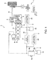
- Fig. 1 is a block diagram schematically illustrating the overall configuration of a hybrid vehicle to which the power control device according to this embodiment of the present disclosure is applied.
- a hybrid vehicle 1 mainly includes an engine 11, a gear-driven starter 12, an ISG (Integrated Starter Generator) 13, a lithium ion battery 14, a DC-DC converter 17 that is a voltage converter, a lead storage battery 19, a high-voltage electrical load 20, and a low-voltage electrical load 21.
- the lithium ion battery 14 is suitably referred to as a "high-voltage battery 14," and the lead storage battery 19 is suitably referred to as a "low-voltage battery 19.”
- the high-voltage battery 14 may be different from the lithium ion battery.
- the low-voltage battery 19 may be different from the lead storage battery.
- the engine 11 is an internal combustion engine (a gasoline engine or a diesel engine) which generates a driving force for the hybrid vehicle 1.
- the driving force of the engine 11 is particularly transmitted to wheels 5 through an output shaft 9, a transmission 2, a reduction gear 3, and a drive shaft 4.
- the output shaft 9 of the engine 11 is coupled to the gear-driven starter 12 through gears.
- the gear-driven starter 12 starts the engine 11 by using power supplied from the low-voltage battery 19, when an ignition switch 22 ( Fig. 2 ) is turned ON by a driver.
- the hybrid vehicle 1 has a brake system 7 for giving a braking force according to operation of a brake pedal by a driver to the vehicle 1.
- This brake system 7 is comprised of an electric brake.
- the engine 11 may not be used as a driving source of the hybrid vehicle 1.
- the ISG 13 is a motor generator provided with a power generation function for generating power by being driven by the engine 11, and an electric drive function for generating a driving force for the hybrid vehicle 1.
- the ISG 13 is coupled to the output shaft 9 of the engine 11 through a belt 8.
- the ISG 13 is electrically connected to the high-voltage battery 14 through a resistor 6a and one or more switch elements 6b and 6c. These switch elements 6b and 6c function as relay devices which change connection/disconnection of the DC-DC converter 17 with the high-voltage battery 14.
- the switch element 6b on the side where the resistor 6a is provided is turned ON to prevent damage of the electronic components by inrush current, etc. Then, the switch element 6c is turned ON to maintain the connection between the ISG 13 and the high-voltage battery 14.
- the ISG 13 when the ISG 13 operates for the power generation function, it functions as a generator which generates power by rotating a rotor which rotates in a magnetic field while being interlocked with the output shaft 9 of the engine 11.
- the ISG 13 has a rectifier (not illustrated) therein and converts the generated AC power into DC power by using the rectifier.
- the power generated by the ISG 13 is supplied to the high-voltage battery 14 and charges it, or is supplied to the high-voltage electric load 20.
- the ISG 13 operates for the electric drive function, it drives the output shaft 9 of the engine 11 through the belt 8 by using the power stored in the high-voltage battery 14.
- a pendulum type variable tension tensioner decoupling alternator tensioner
- the high-voltage battery 14 includes a plurality of batteries, particularly lithium ion batteries, connected in series
- the low-voltage battery 19 includes a plurality of batteries, particularly lead storage batteries, connected in series.
- the nominal voltage of the high-voltage battery 14 is 24VDC or about 24VDC
- the nominal voltage of the low-voltage battery 19 is 12VDC or about 12VDC.
- the high-voltage battery 14 and the low-voltage battery 19 store electric energy by way of a chemical reaction, they are not suitable for rapid charge and discharge, but they have a characteristic of being able to store a comparatively large amount of power because they are easily able to secure charge capacities.
- the DC-DC converter 17 is provided between the high-voltage battery 14 and the low-voltage battery 19.
- the DC-DC converter 17 outputs the input voltage after it changed the voltage, for example, by ON/OFF switching of the built-in switching element.
- the DC-DC converter 17 lowers the output voltage of the high-voltage battery 14 and supplies it to the low-voltage battery 19 to charge the low-voltage battery 19.
- the DC-DC converter 17 lowers the voltage of about 24VDC supplied from the high-voltage battery 14 to about 12VDC and outputs it to the low-voltage battery 19.
- the output of the DC-DC converter 17 is connected to a converter output current sensor 18 which is a current sensor for detecting an output current from the DC-DC converter 17.
- a converter output current sensor 18 which is a current sensor for detecting an output current from the DC-DC converter 17.
- Currents supplied to the low-voltage battery 19, the low-voltage electric load 21, etc. from the DC-DC converter 17 flow through the converter output current sensor 18 which can measure the sum total value of these currents.
- the high-voltage electric load 20 is an electric load which operates, for example, at the voltage of about 24VDC
- the low-voltage electric load 21 is an electric load which operates, for example, at the voltage of about 12VDC, which is lower than that of the high-voltage electric load 20.
- At least one of the power generated by the ISG 13 and the power charged in the high-voltage battery 14 is supplied to the high-voltage electric load 20.
- the high-voltage electric load 20 includes a heater (a seat heater, etc.)
- the low-voltage electric load 21 includes an electrically assisted power steering system (EAPS), an air-conditioner, and an audiovisual apparatus.
- EAPS electrically assisted power steering system
- FIG. 2 is a block diagram schematically illustrating the electrical configuration of the power control device according to this embodiment of the present disclosure.
- the hybrid vehicle 1 is particularly controlled by a controller 10 as illustrated in Fig. 2 .
- This controller 10 is comprised of a computer provided with one or more processors, various kinds of programs interpreted and executed by the processor (including a primary control program, such as operating system (OS), and application program(s) which is activated on the OS to implement specific function(s)), and internal memory, such as ROM and RAM, which store the program(s) and various kinds of data.
- OS operating system
- RAM random access memory
- the controller 10 mainly accepts inputs of detection signals corresponding to parameters detected by at least one of the ignition switch 22, a converter input voltage sensor 30, a battery voltage sensor 34, a battery temperature sensor 35, an ISG temperature sensor 36, the converter output current sensor 18, and an engine hood sensor 38.
- the ignition switch 22 outputs a state of the ignition switch 22 to the controller 10.
- the converter input voltage sensor 30 detects an input voltage of the DC-DC converter 17.
- the battery voltage sensor 34 detects terminal voltages of the high-voltage battery 14 and the low-voltage battery 19.
- the battery temperature sensor 35 detects temperature of the low-voltage battery 19.
- the ISG temperature sensor 36 detects temperature of the ISG 13.
- the converter output current sensor 18 detects the current outputted from the DC-DC converter 17.
- the hood sensor 38 outputs a detection signal indicative of whether a hood of the vehicle 1 is in an open state or a closed state.
- the controller 10 outputs respective control signals to the ISG 13, the DC-DC converter 17, the gear-driven starter 12, the switch elements 6b and 6c, the high-voltage electric load 20, and the low-voltage electric load 21 based on the detection signals from the respective sensors 18, 30, 34, 35, 36, and 38 described above.
- the controller 10 controls the power generation operation and electrically driving operation of the ISG 13, the voltage lowering operation by the DC-DC converter 17, the driving and suspension of the high-voltage electric load 20, the low-voltage electric load 21, and the gear-driven starter 12, and ON/OFF of the switch elements 6b and 6c.
- the controller 10 executes, by using at least the ISG 13, one or a plurality of controls defined according to the operating state of the hybrid vehicle 1 for the purpose of improving fuel efficiency, etc.
- the one or the plurality of controls include an acceleration assist control for generating power from the ISG 13 to assist the acceleration by the engine 11 when the hybrid vehicle 1 accelerates, a slowdown regeneration control for regenerating power by the ISG 13 when the hybrid vehicle 1 slows down, a non-generating control for inhibiting power generation by the ISG 13 for supplying the power to the high-voltage electric load 20 and the low-voltage electric load 21 when a given condition (e.g., a situation to prevent an increase in the load of the engine 11 due to the power generation by the ISG 13) is satisfied, and an idling stop control for automatically stopping the engine 11 when the hybrid vehicle 1 stops and for generating power from the ISG 13 to restart the engine 11 when the hybrid vehicle 1 then departs.
- an acceleration assist control for generating power from the ISG 13 to assist the acceleration by the engine 11 when the hybrid vehicle 1 accelerates
- a slowdown regeneration control for regenerating power by the ISG 13 when the hybrid vehicle 1 slows down
- a non-generating control for inhibiting power generation
- the controller 10 executes a control for operating each of the high-voltage electric load 20 and the low-voltage electric load 21.
- the controller 10 executes a control for supplying at least one of the power generated by the ISG 13 and the power charged in the high-voltage battery 14 to the high-voltage electric load 20.
- the controller 10 executes a control for supplying to the low-voltage electric load 21 at least one of the power charged in the high-voltage battery 14 and lowered in the voltage by the DC-DC converter 17, and the power charged in the low-voltage battery 19.
- the power control device is mainly comprised of the ISG 13 as a “generator,” the high-voltage battery 14, the low-voltage battery 19, the DC-DC converter 17 as a “voltage converter,” and the controller 10.
- FIGs. 3A and 3B illustrate a flowchart of operation of the power control device according to this embodiment of the present disclosure. All of the steps as shown in Figs. 3A and 3B may not be necessarily executed.
- Fig. 4 is a time chart illustrating the operation of the power control device according to this embodiment of the present disclosure.
- the flowchart illustrated in Figs. 3A and 3B illustrates control processing of the DC-DC converter 17 executed by the controller 10 after or immediately after the hybrid vehicle 1 is powered ON.
- the time chart of Fig. 4 illustrates one example of the operation of the power control device after or immediately after the hybrid vehicle 1 is powered ON.
- a state of the ignition switch 22, a state of the gear-driven starter 12, an engine speed, a target voltage of the low-voltage battery 19, an instructed voltage to the DC-DC converter 17, output current of the DC-DC converter 17, and an output instruction of the DC-DC converter 17 are sequentially illustrated from the top.
- the flowchart illustrated in Figs. 3A and 3B is executed particularly by the controller 10.
- the hybrid vehicle 1 is powered ON at a time t 1 .
- the phrase "the vehicle is powered ON" as used herein means that the electric apparatus(es) (the high-voltage electric load 20 and/or the low-voltage electric load 21) mounted on the vehicle is made into a usable state.
- the ignition switch 22 can be turned ON by a key operation, and the vehicle can be powered ON by rotating a key from the "Lock” position to the "ACC (accessory power ON) position," or to the "ON (ignition power ON) position.” Moreover, in a push start button type vehicle, the vehicle can be powered ON by pushing a start button once (accessory power ON) or twice (ignition power ON), for example.
- the switch element 6c is switched to the position of CLOSE. That is, the controller 10 particularly sends the control signal to the switch element 6c to switch the switch element 6c, which is a relay device, to the CLOSE position so that the high-voltage battery 14 is connected to the ISG 13 which is a generator, and the high-voltage battery 14 is connected to the DC-DC converter 17.
- Step S2 the controller 10 particularly determines whether the hood (not illustrated) of the hybrid vehicle 1 is in an open state or a closed state based on the detection signal transmitted from the hood sensor 38. If the hood is closed, the controller 10 particularly shifts to Step S3, and on the other hand, if the hood is opened, the controller 10 particularly shifts to Step S15.
- Step S15 the switch element 6c is again switched to the OPEN position, and the controller 10 particularly ends the processing of the flowchart illustrated in Figs. 3A and 3B in the state where the DC-DC converter 17 is disconnected from the high-voltage battery 14. That is, it is assumed in the state where the hood is opened that the maintenance of the hybrid vehicle 1 is performed. However, for example, in a state where the high-voltage battery 14 is connected to the DC-DC converter 17 and the low-voltage battery 19 is charged through the DC-DC converter 17 controlled by the controller 10, an update of the control program etc. of the controller 10 cannot be performed. Therefore, when the hood is opened, the controller 10 particularly switches the switch element 6c to the OPEN position so that various maintenances are possible.
- the controller 10 since the hood is not opened (i.e., the hood is closed), the controller 10 particularly shifts the processing in the flowchart to Step S3, where it determines an amount of charge (SOC: State of Charge) of the high-voltage battery 14.
- SOC State of Charge
- the controller 10 particularly estimates the amount of charge of the high-voltage battery 14 based on the terminal voltage of the high-voltage battery 14 detected by the battery voltage sensor 34, and if this amount of charge is 50% or more, the controller 10 particularly shifts to Step S4.
- Step S15 the controller 10 particularly shifts to Step S15, where it switches the switch element 6c to the OPEN position similar to the case where the hood is open, and then ends the processing of the flowchart illustrated in Figs. 3A and 3B . That is, if the amount of charge of the high-voltage battery 14 is less than 50%, since the amount of charge of the high-voltage battery 14 may decrease excessively if the output voltage of the high-voltage battery 14 is lowered and the low-voltage battery 19 is charged, one or more processings at and/or after Step S4 will not be performed.
- Step S4 the controller 10 particularly shifts to Step S4, where it transmits an instruction signal for starting the lowering of the output voltage of the high-voltage battery 14 to the DC-DC converter 17. That is, at the time t 1 of the time chart of Fig. 4 , the output instruction of the DC-DC converter 17 is switched from OFF to ON.
- the controller 10 particularly sets the target output voltage to be outputted to the low-voltage battery 19 from the DC-DC converter 17 as 14V. That is, the DC-DC converter 17 lowers the voltage of the power outputted from the high-voltage battery 14 based on the instruction signal from the controller 10, and then lets current flow into the low-voltage battery 19 to charge the low-voltage battery 19.
- the low-voltage battery 19 is not charged.
- the high-voltage battery 14 has the capacity to accept this power, and therefore, the regenerated power can be accumulated effectively in the high-voltage battery 14.
- the low-voltage battery 19 when the lead battery, etc. is used as the low-voltage battery 19, since a natural electric discharge occurs, the low-voltage battery 19 is not normally in a fully-charged state when the vehicle is powered ON, and therefore, the power from the high-voltage battery 14 can be charged to the low-voltage battery 19.
- Step S6 of Fig. 3A the controller 10 again determines based on the detection signal transmitted from the hood sensor 38 whether the hood (not illustrated) of the hybrid vehicle 1 is in the open state or the closed state. If the hood is opened, the controller 10 particularly shifts to Step S16, where the lowering of the voltage by the DC-DC converter 17 is suspended, and it then ends the processing of the flowchart illustrated in Figs. 3A and 3B . That is, even after the lowering of the voltage by the DC-DC converter 17 is started, the lowering of the voltage by the DC-DC converter 17 is suspended when the hood is opened, and the hybrid vehicle 1 is shifted to the state where the maintenance is possible.
- the voltage lowering will not be resumed even after the hood is again closed.
- the lowering of the voltage by the DC-DC converter 17 is resumed after the engine 11 is started.
- the time chart illustrated in Fig. 4 since the hood is not opened after the power is turned ON at the time t 1 , the lowering of the voltage by the DC-DC converter 17 is continued.
- the controller 10 particularly determines an amount of charge of the high-voltage battery 14.
- the controller 10 particularly estimates the amount of charge of the high-voltage battery 14 based on the terminal voltage of the high-voltage battery 14, and if the amount of charge is 50% or more, the controller 10 particularly shifts to Step S8.
- Step S16 where it suspends the lowering of the voltage by the DC-DC converter 17 similar to the case where the hood is opened, and ends the processing of the flowchart illustrated in Figs. 3A and 3B . That is, even after the charging of the low-voltage battery 19 from the high-voltage battery 14 is started, the charging of the low-voltage battery 19 is stopped when the amount of charge of the high-voltage battery 14 decreases to less than 50%. Therefore, an excessive decrease in the amount of charge of the high-voltage battery 14 is prevented. In the time chart illustrated in Fig. 4 , since the amount of charge of the high-voltage battery 14 is not decreased to less than 50% after the charging of the low-voltage battery 19 is started at the time t 1 , the lowering of the voltage by the DC-DC converter 17 is continued.
- Step S8 of Fig. 3A the controller 10 particularly determines whether the starter switch of the engine 11 is turned ON, and if turned ON, the controller 10 particularly shifts to Step S9 of Fig. 3B , and on the other hand, if not turned ON, it returns to Step S6. That is, in the flowchart of Fig. 3A , after the lowering of the voltage by the DC-DC converter 17 is started, processings at Steps S6 ⁇ S7 ⁇ S8 ⁇ S6 are repeated until the starter switch is turned ON. In this embodiment, the starter switch of the engine 11 is turned ON by rotating the ignition switch 22 of the vehicle to the "START" position from the "ON" position.
- the charging current to the low-voltage battery 19 and the current supplied to the low-voltage electric load 21 are outputted through the DC-DC converter 17.
- the output current from the DC-DC converter 17 increases.
- the output current from the DC-DC converter 17 is kept at less than or equal to a given first current. Note that although the output current from the DC-DC converter 17 is kept at less than or equal to a given maximum current during the operation of the engine 11, the first current set before the engine 11 is started is set at a current that is less than the maximum current.
- the output current is controlled to the first current that is less than the maximum current before the engine 11 is started.
- the first current is set as 20A, and when the output current reaches 20A, the output voltage of the DC-DC converter 17 is lowered to decrease the charging current to the low-voltage battery 19.
- the controller 10 When the starter switch is turned ON, the controller 10 particularly shifts the processing in the flowchart to Step S9 of Fig. 3B , where it suspends the lowering of the voltage by the DC-DC converter 17. That is, the controller 10 particularly transmits the control signal to the DC-DC converter 17 to suspend the lowering of the voltage by the DC-DC converter 17.
- Step S10 the controller 10 particularly determines whether the suspension processing of the DC-DC converter 17 is finished. That is, when the suspension processing is finished, the DC-DC converter 17 into which the control signal for suspension the voltage lowering is inputted from the controller 10 particularly returns to the controller 10 a signal indicating that the suspension processing is finished.
- the controller 10 determines that the suspension processing of the DC-DC converter 17 is finished. If the suspension processing is finished, the controller 10 particularly shifts to Step S12, and on the other hand, if the suspension processing is not finished, the controller 10 shifts to Step S11.
- the controller 10 particularly determines whether a given time is lapsed after the control signal is transmitted to the DC-DC converter 17 at Step S9, and if the given time is lapsed, the controller 10 particularly shifts to Step S12, and on the other hand, if the given time is not lapsed, it returns to Step S10.
- the controller 10 particularly executes the processing at Step S12. Therefore, even when the signal indicating that the suspension processing is finished is not received because of a certain reason, the controller 10 can certainly execute the processings at and after Step S12.
- Step S12 the controller 10 particularly drives the gear-driven starter 12 to crank the engine 11.
- the ignition switch 22 is rotated to the "START" position at the time t 2 (or the starter switch is operated to be “ON”).
- the controller 10 particularly switches the output instruction to the DC-DC converter 17 to "OFF,” and makes the output current of the DC-DC converter 17 to zero.
- the gear-driven starter 12 being driven, the rotating speed of the output shaft 9 of the engine 11 increases.
- the controller 10 when the engine 11 is started at Step S13, the controller 10 particularly resumes the lowering of the voltage by the DC-DC converter 17 at Step S14, and then ends the processing of the flowchart illustrated in Figs. 3A and 3B .
- the controller 10 In the time chart of Fig. 4 , after the gear-driven starter 12 is driven at the time t 2 , the controller 10 particularly starts the engine at a time t 3 .
- the controller 10 particularly switches the output instruction to the DC-DC converter 17 to "ON" to resume the current output from the DC-DC converter 17.
- the controller 10 sets the output current from the DC-DC converter 17 based on the output currents required for the high-voltage battery 14 and the low-voltage battery 19, the amount of charge of these batteries, etc.
- the output current from the DC-DC converter 17 is restricted to current below the given maximum current set larger than the first current (20A).
- the output instruction to the DC-DC converter 17 is turned “OFF,” and the low-voltage battery target voltage and the DC-DC converter instructed voltage are maintained at the values before the cranking is started.
- the output instruction to the DC-DC converter 17 is turned “OFF,” the output current from the DC-DC converter 17 is set to zero, regardless of the target voltage or the instructed voltage.
- the present disclosure may be configured so that the low-voltage battery target voltage and the DC-DC converter instructed voltage are lowered or set to zero corresponding to the output instruction to the DC-DC converter 17.
- the present disclosure may also be configured so that the charging of the low-voltage battery 19 is suspended by reducing the low-voltage battery target voltage and the DC-DC converter instructed voltage or setting them to zero, while maintaining the output instruction to the DC-DC converter 17 at "ON.”
- the low-voltage battery 19 can be prevented from being insufficiently charged, even if the low-voltage electric load 21 is used for a comparatively long period of time before the engine startup.
- the DC-DC converter 17 is operated and the output voltage from the high-voltage battery 14 is lowered to charge the low-voltage battery 19. Therefore, even when the high-voltage battery 14 is fully-charged, the high-voltage battery 14 still has the capacity to be charged when starting the engine and it becomes possible to charge the high-voltage battery 14 with the power regenerated during the operation of the vehicle 1, thereby effectively utilizing the regenerated power.
- the power control device of this embodiment while the vehicle 1 is powered ON, if the voltage of the high-voltage battery 14 is below the given voltage, since the charging of the low-voltage battery 19 by the DC-DC converter 17 is not started (Steps S3 ⁇ S15 of Fig. 3A ), the high-voltage battery 14 being insufficiently charged due to charging the low-voltage battery 19 can be avoided.
- the power control device of this embodiment after the vehicle 1 is powered ON and before the engine is started, since the output current from the DC-DC converter 17 is restricted to or below the given first current which is lower than the maximum current, the temperature of the DC-DC converter 17 excessively increasing before the engine is started can be prevented. Therefore, it can be prevented that it becomes impossible to supply the required current from the DC-DC converter 17 during the operation of the vehicle 1 after the engine 11 is started.
- the power control device of this embodiment in the state where the cranking is performed (from the time t 2 to the time t 3 of Fig. 4 ), since the charging of the low-voltage battery 19 from the high-voltage battery 14 is suspended, it can be prevented that the current is excessively drawn from the high-voltage battery 14 and the excessive voltage drop, etc. occurs.
Abstract
Description
- The present disclosure relates to a power control device for a vehicle, and particularly to a control device for a power supply mounted on the vehicle. The present disclosure also relates to a vehicle, a method of controlling a vehicle, and a computer program product.
-
JP2016-118126A - Like
JP2016-118126A - However, after the vehicle is powered ON (after turning an ignition switch to an "ON" position) and before the engine is started, electric apparatuses mounted on the vehicle may be used for a comparatively long period of time, and in such a case, a problem arises in that the electrical energy accumulated in the low-voltage battery runs out. Moreover, if the vehicle is operated in a state where the high-voltage battery is fully-charged, electrical energy regenerated by the generator cannot be accumulated in the high-voltage battery, and therefore, there is a problem in that the regenerated electric energy cannot effectively be utilized.
- Therefore, the present disclosure is made in view of the above situation, and one purpose thereof is fully using in-vehicle electric apparatuses and effectively utilizing electrical energy regenerated by a generator, even before the engine is started.
- According to one aspect of the present disclosure, a power control device for a power supply mounted on a vehicle or a power control device for a vehicle is provided, which includes a generator mounted on the vehicle and configured to regenerate power from kinetic energy of the vehicle, a high-voltage battery configured to accumulate the power regenerated by the generator, a low-voltage battery of which a nominal voltage is lower than the high-voltage battery, a voltage converter configured to lower an output voltage from the high-voltage battery and charge the low-voltage battery at the lowered voltage, and a controller configured to control the voltage converter. The controller operates the voltage converter to start the charging of the low-voltage battery after the vehicle is powered ON and before an engine mounted on the vehicle is started.
- According to this configuration, the generator regenerates the power from the kinetic energy of the vehicle, and the generated power is accumulated in the high-voltage battery. The voltage converter lowers the output voltage from the high-voltage battery, and charges at the lowered voltage the low-voltage battery of which the nominal voltage is lower than the high-voltage battery. The controller operates the voltage converter to start charging the low-voltage battery after the vehicle is powered ON and before the engine mounted on the vehicle is started.
- According to this configuration, since the voltage converter is operated and the charging of the low-voltage battery is started after the vehicle is powered ON and before the engine is started, the low-voltage battery can be prevented from being insufficiently charged, even if in-vehicle electric apparatuses are used for a comparatively long period of time before the engine startup. Moreover, according to this configuration, before the mounted engine is started, the voltage converter is operated and the output voltage from the high-voltage battery is lowered to charge the low-voltage battery. Therefore, even when the high-voltage battery is fully-charged, the high-voltage battery still has the capacity to be charged when starting the engine and it becomes possible to charge the high-voltage battery with the power regenerated during the operation of the vehicle, thereby effectively utilizing the regenerated power.
- The controller may inhibit the voltage converter from starting the charging of the low-voltage battery, when the voltage of the high-voltage battery is below a given voltage while the vehicle is powered ON.
- According to this configuration, while the vehicle is powered ON, if the voltage of the high-voltage battery is below the given voltage, since the charging of the low-voltage battery by the voltage converter is not started, the high-voltage battery being insufficiently charged due to charging the low-voltage battery can be avoided.
- The controller may control the voltage converter so that an output current from the voltage converter becomes below a given maximum current after the engine is started, and particularly, restrict the output current below a given first current lower than the maximum current after the vehicle is powered ON and before the engine is started.
- In general, the voltage converter generates power by outputting a large current. Thus, when the voltage converter outputs the large current for a comparatively long period of time, its temperature rises, and therefore, the output current cannot avoid being lowered to protect the voltage converter. According to this configuration, after the vehicle is powered ON and before the engine is started, since the output current from the voltage converter is restricted to or below the given first current which is lower than the maximum current, excessive increase of the temperature of the voltage converter before the engine is started can be prevented. Therefore, it can be prevented that it becomes impossible to supply the required current from the voltage converter during the operation of the vehicle after the engine is started.
- The controller may control the voltage converter so that the charging of the low-voltage battery from the high-voltage battery is suspended while cranking is performed, or a starter motor is driven, after the vehicle is powered ON.
- In general, when the cranking is performed, a comparatively large current is needed to drive a starter motor. According to this configuration, in the state where the cranking is performed, since the charging of the low-voltage battery from the high-voltage battery is suspended, the current being excessively drawn from the high-voltage battery and the excessive voltage drop, etc. can be prevented from occurring.
- The power control device may further include a relay device configured to switch between a connected state and a disconnected state of the high-voltage battery and the voltage converter, and a hood sensor configured to detect an open state and a closed state of a hood of the vehicle. The controller may switch the relay device to the disconnected state or maintain the relay device in the disconnected state, when the open state of the hood is detected by the hood sensor after the vehicle is powered ON.
- When the hood of the vehicle is in the open state, it is considered that maintenance of the vehicle, such as an update of the control program of the power control device, is to be performed. However, if the voltage converter is operated and the charging of the low-voltage battery is performed after the vehicle is powered ON and before the engine is started, a part of the maintenance cannot be performed. According to this configuration, when the open state of the hood is detected by the hood sensor, since the relay device which switches connection/disconnection of the voltage converter to the high-voltage battery is switched to the disconnected state, the maintenance of the vehicle can be prevented from being impeded.
- The controller may increase a target voltage when operating the voltage converter to charge the low-voltage battery after the vehicle is powered ON and before the engine is started.
- According to this configuration, by increasing the target voltage of the low-voltage battery while the power is turned ON, the amount of charge to the low-voltage battery from the high-voltage battery increases and the high-voltage battery has more capacity to be charged, thereby effectively utilizing the regenerated power.
- Particularly, a vehicle includes the above power control device.
- According to another aspect of the present disclosure, a method of controlling a power supply for a vehicle, or a method of controlling a vehicle is provided, which includes the steps of regenerating power from kinetic energy of the vehicle, accumulating the regenerated power in a high-voltage battery having a higher nominal voltage than a low-voltage battery, lowering, by a voltage converter, an output voltage from the high-voltage battery and charging the low-voltage battery at the lowered voltage, and controlling the voltage converter to start the charging of the low-voltage battery after the vehicle is powered ON and before an engine mounted on the vehicle is started.
- Particularly, a computer program product includes computer-readable instructions which, when loaded and executed on the above power control device, perform the above method.
-
-
Fig. 1 is a block diagram schematically illustrating the overall configuration of a hybrid vehicle to which a power control device for a vehicle according to one embodiment of the present disclosure is applied. -
Fig. 2 is a block diagram schematically illustrating an electrical configuration of the power control device for the vehicle according to this embodiment of the present disclosure. -
Figs. 3A and3B illustrate a flowchart of operation of the power control device for the vehicle according to this embodiment of the present disclosure. -
Fig. 4 is a time chart illustrating operation of the power control device for the vehicle according to this embodiment of the present disclosure. - Next, a power control device for a vehicle according to one embodiment of the present disclosure is described with reference to the accompanying drawings.
- First, a device configuration of the power control device according to this embodiment of the present disclosure is described.
Fig. 1 is a block diagram schematically illustrating the overall configuration of a hybrid vehicle to which the power control device according to this embodiment of the present disclosure is applied. As illustrated inFig. 1 , ahybrid vehicle 1 mainly includes anengine 11, a gear-drivenstarter 12, an ISG (Integrated Starter Generator) 13, alithium ion battery 14, a DC-DC converter 17 that is a voltage converter, alead storage battery 19, a high-voltageelectrical load 20, and a low-voltageelectrical load 21. Below, since the voltage (nominal voltage) of thelithium ion battery 14 is higher than the voltage (nominal voltage) of thelead storage battery 19, thelithium ion battery 14 is suitably referred to as a "high-voltage battery 14," and thelead storage battery 19 is suitably referred to as a "low-voltage battery 19." The high-voltage battery 14 may be different from the lithium ion battery. Similarly, the low-voltage battery 19 may be different from the lead storage battery. - The
engine 11 is an internal combustion engine (a gasoline engine or a diesel engine) which generates a driving force for thehybrid vehicle 1. The driving force of theengine 11 is particularly transmitted towheels 5 through anoutput shaft 9, atransmission 2, areduction gear 3, and adrive shaft 4. Theoutput shaft 9 of theengine 11 is coupled to the gear-drivenstarter 12 through gears. The gear-drivenstarter 12 starts theengine 11 by using power supplied from the low-voltage battery 19, when an ignition switch 22 (Fig. 2 ) is turned ON by a driver. Moreover, thehybrid vehicle 1 has abrake system 7 for giving a braking force according to operation of a brake pedal by a driver to thevehicle 1. Thisbrake system 7 is comprised of an electric brake. Theengine 11 may not be used as a driving source of thehybrid vehicle 1. - The
ISG 13 is a motor generator provided with a power generation function for generating power by being driven by theengine 11, and an electric drive function for generating a driving force for thehybrid vehicle 1. TheISG 13 is coupled to theoutput shaft 9 of theengine 11 through abelt 8. Moreover, theISG 13 is electrically connected to the high-voltage battery 14 through aresistor 6a and one ormore switch elements switch elements DC converter 17 with the high-voltage battery 14. - When first connecting the
ISG 13 with the high-voltage battery 14, theswitch element 6b on the side where theresistor 6a is provided is turned ON to prevent damage of the electronic components by inrush current, etc. Then, theswitch element 6c is turned ON to maintain the connection between theISG 13 and the high-voltage battery 14. - Moreover, when the
ISG 13 operates for the power generation function, it functions as a generator which generates power by rotating a rotor which rotates in a magnetic field while being interlocked with theoutput shaft 9 of theengine 11. TheISG 13 has a rectifier (not illustrated) therein and converts the generated AC power into DC power by using the rectifier. - The power generated by the
ISG 13 is supplied to the high-voltage battery 14 and charges it, or is supplied to the high-voltageelectric load 20. On the other hand, when theISG 13 operates for the electric drive function, it drives theoutput shaft 9 of theengine 11 through thebelt 8 by using the power stored in the high-voltage battery 14. Note that in order to adjust the tension of thebelt 8, for example, when switching theISG 13 between the operation for the power generation function and the operation for the electric drive function, a pendulum type variable tension tensioner (decoupling alternator tensioner) may be applied to thebelt 8. - The high-
voltage battery 14 includes a plurality of batteries, particularly lithium ion batteries, connected in series, and the low-voltage battery 19 includes a plurality of batteries, particularly lead storage batteries, connected in series. For example, the nominal voltage of the high-voltage battery 14 is 24VDC or about 24VDC, and the nominal voltage of the low-voltage battery 19 is 12VDC or about 12VDC. - Since the high-
voltage battery 14 and the low-voltage battery 19 store electric energy by way of a chemical reaction, they are not suitable for rapid charge and discharge, but they have a characteristic of being able to store a comparatively large amount of power because they are easily able to secure charge capacities. - The DC-
DC converter 17 is provided between the high-voltage battery 14 and the low-voltage battery 19. The DC-DC converter 17 outputs the input voltage after it changed the voltage, for example, by ON/OFF switching of the built-in switching element. In detail, the DC-DC converter 17 lowers the output voltage of the high-voltage battery 14 and supplies it to the low-voltage battery 19 to charge the low-voltage battery 19. For example, the DC-DC converter 17 lowers the voltage of about 24VDC supplied from the high-voltage battery 14 to about 12VDC and outputs it to the low-voltage battery 19. - Moreover, the output of the DC-
DC converter 17 is connected to a converter outputcurrent sensor 18 which is a current sensor for detecting an output current from the DC-DC converter 17. Currents supplied to the low-voltage battery 19, the low-voltageelectric load 21, etc. from the DC-DC converter 17 flow through the converter outputcurrent sensor 18 which can measure the sum total value of these currents. - The high-voltage
electric load 20 is an electric load which operates, for example, at the voltage of about 24VDC, and the low-voltageelectric load 21 is an electric load which operates, for example, at the voltage of about 12VDC, which is lower than that of the high-voltageelectric load 20. At least one of the power generated by theISG 13 and the power charged in the high-voltage battery 14 is supplied to the high-voltageelectric load 20. - Moreover, at least one of the power which is generated by the
ISG 13, charged in the high-voltage battery 14, and lowered in the voltage by the DC-DC converter 17, and the power charged in the low-voltage battery 19 is supplied to the low-voltageelectric load 21. In one example, the high-voltageelectric load 20 includes a heater (a seat heater, etc.), the low-voltageelectric load 21 includes an electrically assisted power steering system (EAPS), an air-conditioner, and an audiovisual apparatus. - Next, referring to
Fig. 2 , an electrical configuration of the power control device according to this embodiment of the present disclosure is described.Fig. 2 is a block diagram schematically illustrating the electrical configuration of the power control device according to this embodiment of the present disclosure. - In this embodiment, the
hybrid vehicle 1 is particularly controlled by acontroller 10 as illustrated inFig. 2 . Thiscontroller 10 is comprised of a computer provided with one or more processors, various kinds of programs interpreted and executed by the processor (including a primary control program, such as operating system (OS), and application program(s) which is activated on the OS to implement specific function(s)), and internal memory, such as ROM and RAM, which store the program(s) and various kinds of data. - In detail, as illustrated in
Fig. 2 , thecontroller 10 mainly accepts inputs of detection signals corresponding to parameters detected by at least one of theignition switch 22, a converterinput voltage sensor 30, abattery voltage sensor 34, abattery temperature sensor 35, anISG temperature sensor 36, the converter outputcurrent sensor 18, and anengine hood sensor 38. Theignition switch 22 outputs a state of theignition switch 22 to thecontroller 10. The converterinput voltage sensor 30 detects an input voltage of the DC-DC converter 17. - The
battery voltage sensor 34 detects terminal voltages of the high-voltage battery 14 and the low-voltage battery 19. Thebattery temperature sensor 35 detects temperature of the low-voltage battery 19. TheISG temperature sensor 36 detects temperature of theISG 13. - The converter output
current sensor 18 detects the current outputted from the DC-DC converter 17. Thehood sensor 38 outputs a detection signal indicative of whether a hood of thevehicle 1 is in an open state or a closed state. - Moreover, the
controller 10 outputs respective control signals to theISG 13, the DC-DC converter 17, the gear-drivenstarter 12, theswitch elements electric load 20, and the low-voltageelectric load 21 based on the detection signals from therespective sensors - Thus, the
controller 10 controls the power generation operation and electrically driving operation of theISG 13, the voltage lowering operation by the DC-DC converter 17, the driving and suspension of the high-voltageelectric load 20, the low-voltageelectric load 21, and the gear-drivenstarter 12, and ON/OFF of theswitch elements - Typically, the
controller 10 executes, by using at least theISG 13, one or a plurality of controls defined according to the operating state of thehybrid vehicle 1 for the purpose of improving fuel efficiency, etc. - The one or the plurality of controls include an acceleration assist control for generating power from the
ISG 13 to assist the acceleration by theengine 11 when thehybrid vehicle 1 accelerates, a slowdown regeneration control for regenerating power by theISG 13 when thehybrid vehicle 1 slows down, a non-generating control for inhibiting power generation by theISG 13 for supplying the power to the high-voltageelectric load 20 and the low-voltageelectric load 21 when a given condition (e.g., a situation to prevent an increase in the load of theengine 11 due to the power generation by the ISG 13) is satisfied, and an idling stop control for automatically stopping theengine 11 when thehybrid vehicle 1 stops and for generating power from theISG 13 to restart theengine 11 when thehybrid vehicle 1 then departs. - Further, the
controller 10 executes a control for operating each of the high-voltageelectric load 20 and the low-voltageelectric load 21. In detail, when operating the high-voltageelectric load 20, thecontroller 10 executes a control for supplying at least one of the power generated by theISG 13 and the power charged in the high-voltage battery 14 to the high-voltageelectric load 20. - On the other hand, when operating the low-voltage
electric load 21, thecontroller 10 executes a control for supplying to the low-voltageelectric load 21 at least one of the power charged in the high-voltage battery 14 and lowered in the voltage by the DC-DC converter 17, and the power charged in the low-voltage battery 19. - Note that "the power control device" according to this embodiment of the present disclosure is mainly comprised of the
ISG 13 as a "generator," the high-voltage battery 14, the low-voltage battery 19, the DC-DC converter 17 as a "voltage converter," and thecontroller 10. - Next, referring to
Figs. 3A and3B , and4 , operation of the power control device according to this embodiment of the present disclosure is described.Figs. 3A and3B illustrate a flowchart of operation of the power control device according to this embodiment of the present disclosure. All of the steps as shown inFigs. 3A and3B may not be necessarily executed.Fig. 4 is a time chart illustrating the operation of the power control device according to this embodiment of the present disclosure. - The flowchart illustrated in
Figs. 3A and3B illustrates control processing of the DC-DC converter 17 executed by thecontroller 10 after or immediately after thehybrid vehicle 1 is powered ON. The time chart ofFig. 4 illustrates one example of the operation of the power control device after or immediately after thehybrid vehicle 1 is powered ON. InFig. 4 , a state of theignition switch 22, a state of the gear-drivenstarter 12, an engine speed, a target voltage of the low-voltage battery 19, an instructed voltage to the DC-DC converter 17, output current of the DC-DC converter 17, and an output instruction of the DC-DC converter 17 are sequentially illustrated from the top. - First, when the
hybrid vehicle 1 is powered ON, the flowchart illustrated inFigs. 3A and3B is executed particularly by thecontroller 10. In the time chart illustrating one example inFig. 4 , thehybrid vehicle 1 is powered ON at a time t1. Note that the phrase "the vehicle is powered ON" as used herein means that the electric apparatus(es) (the high-voltageelectric load 20 and/or the low-voltage electric load 21) mounted on the vehicle is made into a usable state. - In this embodiment, the
ignition switch 22 can be turned ON by a key operation, and the vehicle can be powered ON by rotating a key from the "Lock" position to the "ACC (accessory power ON) position," or to the "ON (ignition power ON) position." Moreover, in a push start button type vehicle, the vehicle can be powered ON by pushing a start button once (accessory power ON) or twice (ignition power ON), for example. - At Step S1 of the flowchart illustrated in
Fig. 3A , theswitch element 6c is switched to the position of CLOSE. That is, thecontroller 10 particularly sends the control signal to theswitch element 6c to switch theswitch element 6c, which is a relay device, to the CLOSE position so that the high-voltage battery 14 is connected to theISG 13 which is a generator, and the high-voltage battery 14 is connected to the DC-DC converter 17. - Next, at Step S2, the
controller 10 particularly determines whether the hood (not illustrated) of thehybrid vehicle 1 is in an open state or a closed state based on the detection signal transmitted from thehood sensor 38. If the hood is closed, thecontroller 10 particularly shifts to Step S3, and on the other hand, if the hood is opened, thecontroller 10 particularly shifts to Step S15. - At Step S15, the
switch element 6c is again switched to the OPEN position, and thecontroller 10 particularly ends the processing of the flowchart illustrated inFigs. 3A and3B in the state where the DC-DC converter 17 is disconnected from the high-voltage battery 14. That is, it is assumed in the state where the hood is opened that the maintenance of thehybrid vehicle 1 is performed. However, for example, in a state where the high-voltage battery 14 is connected to the DC-DC converter 17 and the low-voltage battery 19 is charged through the DC-DC converter 17 controlled by thecontroller 10, an update of the control program etc. of thecontroller 10 cannot be performed. Therefore, when the hood is opened, thecontroller 10 particularly switches theswitch element 6c to the OPEN position so that various maintenances are possible. - On the other hand, in the time chart illustrated in
Fig. 4 , since the hood is not opened (i.e., the hood is closed), thecontroller 10 particularly shifts the processing in the flowchart to Step S3, where it determines an amount of charge (SOC: State of Charge) of the high-voltage battery 14. In detail, thecontroller 10 particularly estimates the amount of charge of the high-voltage battery 14 based on the terminal voltage of the high-voltage battery 14 detected by thebattery voltage sensor 34, and if this amount of charge is 50% or more, thecontroller 10 particularly shifts to Step S4. - On the other hand, if the amount of charge is less than 50%, the
controller 10 particularly shifts to Step S15, where it switches theswitch element 6c to the OPEN position similar to the case where the hood is open, and then ends the processing of the flowchart illustrated inFigs. 3A and3B . That is, if the amount of charge of the high-voltage battery 14 is less than 50%, since the amount of charge of the high-voltage battery 14 may decrease excessively if the output voltage of the high-voltage battery 14 is lowered and the low-voltage battery 19 is charged, one or more processings at and/or after Step S4 will not be performed. - Next, in the time chart illustrated in
Fig. 4 , since the amount of charge is 50% or more, thecontroller 10 particularly shifts to Step S4, where it transmits an instruction signal for starting the lowering of the output voltage of the high-voltage battery 14 to the DC-DC converter 17. That is, at the time t1 of the time chart ofFig. 4 , the output instruction of the DC-DC converter 17 is switched from OFF to ON. - Further, at Step S5, the
controller 10 particularly sets the target output voltage to be outputted to the low-voltage battery 19 from the DC-DC converter 17 as 14V. That is, the DC-DC converter 17 lowers the voltage of the power outputted from the high-voltage battery 14 based on the instruction signal from thecontroller 10, and then lets current flow into the low-voltage battery 19 to charge the low-voltage battery 19. - Here, if the voltage outputted to the low-
voltage battery 19 from the DC-DC converter 17 is low, although power is supplied to the low-voltageelectric load 21, the charging current does not substantially flow to the low-voltage battery 19, and therefore, the low-voltage battery 19 is not charged. - In this embodiment, by outputting the voltage of 14V from the DC-
DC converter 17 to the low-voltage battery 19 of the 12V nominal voltage to supply the charging current to the low-voltage battery 19 and charge the low-voltage battery 19. Moreover, in the time chart ofFig. 4 , when the power is turned ON at the time t1, the instructed voltage of the DC-DC converter 17 is raised, and the target terminal voltage of the low-voltage battery 19 is also raised, thereby increasing the output current from the DC-DC converter 17. - Thus, by lowering the output of the high-
voltage battery 14 and charging the low-voltage battery 19, the amount of charge of the low-voltage battery 19 increases and the amount of charge of the high-voltage battery 14 decreases. Therefore, even when a large amount of power is regenerated by theISG 13 during the operation of thehybrid vehicle 1, the high-voltage battery 14 has the capacity to accept this power, and therefore, the regenerated power can be accumulated effectively in the high-voltage battery 14. - On the other hand, when the lead battery, etc. is used as the low-
voltage battery 19, since a natural electric discharge occurs, the low-voltage battery 19 is not normally in a fully-charged state when the vehicle is powered ON, and therefore, the power from the high-voltage battery 14 can be charged to the low-voltage battery 19. - Next, at Step S6 of
Fig. 3A , thecontroller 10 again determines based on the detection signal transmitted from thehood sensor 38 whether the hood (not illustrated) of thehybrid vehicle 1 is in the open state or the closed state. If the hood is opened, thecontroller 10 particularly shifts to Step S16, where the lowering of the voltage by the DC-DC converter 17 is suspended, and it then ends the processing of the flowchart illustrated inFigs. 3A and3B . That is, even after the lowering of the voltage by the DC-DC converter 17 is started, the lowering of the voltage by the DC-DC converter 17 is suspended when the hood is opened, and thehybrid vehicle 1 is shifted to the state where the maintenance is possible. - Moreover, in this embodiment, when the hood is opened while the DC-
DC converter 17 is lowering the voltage, and the voltage lowering is suspended, the voltage lowering will not be resumed even after the hood is again closed. In this case, the lowering of the voltage by the DC-DC converter 17 is resumed after theengine 11 is started. In the time chart illustrated inFig. 4 , since the hood is not opened after the power is turned ON at the time t1, the lowering of the voltage by the DC-DC converter 17 is continued. - Further, at Step S7, the
controller 10 particularly determines an amount of charge of the high-voltage battery 14. In detail, thecontroller 10 particularly estimates the amount of charge of the high-voltage battery 14 based on the terminal voltage of the high-voltage battery 14, and if the amount of charge is 50% or more, thecontroller 10 particularly shifts to Step S8. - On the other hand, if the amount of charge is less than 50%, the
controller 10 particularly shifts to Step S16, where it suspends the lowering of the voltage by the DC-DC converter 17 similar to the case where the hood is opened, and ends the processing of the flowchart illustrated inFigs. 3A and3B . That is, even after the charging of the low-voltage battery 19 from the high-voltage battery 14 is started, the charging of the low-voltage battery 19 is stopped when the amount of charge of the high-voltage battery 14 decreases to less than 50%. Therefore, an excessive decrease in the amount of charge of the high-voltage battery 14 is prevented. In the time chart illustrated inFig. 4 , since the amount of charge of the high-voltage battery 14 is not decreased to less than 50% after the charging of the low-voltage battery 19 is started at the time t1, the lowering of the voltage by the DC-DC converter 17 is continued. - Next, at Step S8 of
Fig. 3A , thecontroller 10 particularly determines whether the starter switch of theengine 11 is turned ON, and if turned ON, thecontroller 10 particularly shifts to Step S9 ofFig. 3B , and on the other hand, if not turned ON, it returns to Step S6. That is, in the flowchart ofFig. 3A , after the lowering of the voltage by the DC-DC converter 17 is started, processings at Steps S6→S7→S8→S6 are repeated until the starter switch is turned ON. In this embodiment, the starter switch of theengine 11 is turned ON by rotating theignition switch 22 of the vehicle to the "START" position from the "ON" position. - After the charging of the low-
voltage battery 19 is started at the time t1 ofFig. 4 , the charging current to the low-voltage battery 19 and the current supplied to the low-voltageelectric load 21 are outputted through the DC-DC converter 17. Here, if the amount of charge of the low-voltage battery 19 is small, or if the low-voltageelectric load 21 with a large power consumption is operated, the output current from the DC-DC converter 17 increases. - However, even when a large output current is required for the DC-
DC converter 17, the output current from the DC-DC converter 17 is kept at less than or equal to a given first current. Note that although the output current from the DC-DC converter 17 is kept at less than or equal to a given maximum current during the operation of theengine 11, the first current set before theengine 11 is started is set at a current that is less than the maximum current. - That is, when the large output current is taken out from the DC-
DC converter 17, the temperature of the DC-DC converter 17 increases, and if the large current is continuously taken out and the temperature increases to a given value, the output of current is suspended in order to protect the circuit components of the DC-DC converter 17. Therefore, if the large current is drawn before theengine 11 is started and the temperature of the DC-DC converter 17 is greatly raised, the required power may become impossible to be drawn from the DC-DC converter 17 during the operation of theengine 11. In order to avoid this effect, the output current is controlled to the first current that is less than the maximum current before theengine 11 is started. - In this embodiment, the first current is set as 20A, and when the output current reaches 20A, the output voltage of the DC-
DC converter 17 is lowered to decrease the charging current to the low-voltage battery 19. - On the other hand, in the time chart illustrated in
Fig. 4 , after the charging of the low-voltage battery 19 is started at the time t1, processings at Steps S6→S7→S8→S6 are repeated, and the starter switch is then turned ON at a time t2. - When the starter switch is turned ON, the
controller 10 particularly shifts the processing in the flowchart to Step S9 ofFig. 3B , where it suspends the lowering of the voltage by the DC-DC converter 17. That is, thecontroller 10 particularly transmits the control signal to the DC-DC converter 17 to suspend the lowering of the voltage by the DC-DC converter 17. - Next, at Step S10, the
controller 10 particularly determines whether the suspension processing of the DC-DC converter 17 is finished. That is, when the suspension processing is finished, the DC-DC converter 17 into which the control signal for suspension the voltage lowering is inputted from thecontroller 10 particularly returns to the controller 10 a signal indicating that the suspension processing is finished. - When the signal indicating that the suspension processing is finished is received from the DC-
DC converter 17, thecontroller 10 determines that the suspension processing of the DC-DC converter 17 is finished. If the suspension processing is finished, thecontroller 10 particularly shifts to Step S12, and on the other hand, if the suspension processing is not finished, thecontroller 10 shifts to Step S11. - At Step S11, the
controller 10 particularly determines whether a given time is lapsed after the control signal is transmitted to the DC-DC converter 17 at Step S9, and if the given time is lapsed, thecontroller 10 particularly shifts to Step S12, and on the other hand, if the given time is not lapsed, it returns to Step S10. By this processing, if the signal indicating that the suspension processing is finished is inputted from the DC-DC converter 17 or if the given time is lapsed after the control signal is transmitted at Step S9, thecontroller 10 particularly executes the processing at Step S12. Therefore, even when the signal indicating that the suspension processing is finished is not received because of a certain reason, thecontroller 10 can certainly execute the processings at and after Step S12. - Next, at Step S12, the
controller 10 particularly drives the gear-drivenstarter 12 to crank theengine 11. In the time chart ofFig. 4 , theignition switch 22 is rotated to the "START" position at the time t2 (or the starter switch is operated to be "ON"). In connection with this, thecontroller 10 particularly switches the output instruction to the DC-DC converter 17 to "OFF," and makes the output current of the DC-DC converter 17 to zero. Moreover, by the gear-drivenstarter 12 being driven, the rotating speed of theoutput shaft 9 of theengine 11 increases. - Further, when the
engine 11 is started at Step S13, thecontroller 10 particularly resumes the lowering of the voltage by the DC-DC converter 17 at Step S14, and then ends the processing of the flowchart illustrated inFigs. 3A and3B . In the time chart ofFig. 4 , after the gear-drivenstarter 12 is driven at the time t2, thecontroller 10 particularly starts the engine at a time t3. - In connection with this, the
controller 10 particularly switches the output instruction to the DC-DC converter 17 to "ON" to resume the current output from the DC-DC converter 17. Note that after theengine 11 is started, thecontroller 10 sets the output current from the DC-DC converter 17 based on the output currents required for the high-voltage battery 14 and the low-voltage battery 19, the amount of charge of these batteries, etc. Moreover, after theengine 11 is started, the output current from the DC-DC converter 17 is restricted to current below the given maximum current set larger than the first current (20A). - Note that in the time chart of
Fig. 4 , while the cranking is performed from the time t2 to the time t3, the output instruction to the DC-DC converter 17 is turned "OFF," and the low-voltage battery target voltage and the DC-DC converter instructed voltage are maintained at the values before the cranking is started. Thus, in the power control device of this embodiment, if the output instruction to the DC-DC converter 17 is turned "OFF," the output current from the DC-DC converter 17 is set to zero, regardless of the target voltage or the instructed voltage. Alternatively, the present disclosure may be configured so that the low-voltage battery target voltage and the DC-DC converter instructed voltage are lowered or set to zero corresponding to the output instruction to the DC-DC converter 17. Alternatively, the present disclosure may also be configured so that the charging of the low-voltage battery 19 is suspended by reducing the low-voltage battery target voltage and the DC-DC converter instructed voltage or setting them to zero, while maintaining the output instruction to the DC-DC converter 17 at "ON." - According to the power control device of this embodiment of the present disclosure, since the DC-
DC converter 17 is operated and the charging of the low-voltage battery 19 is started after thevehicle 1 is powered ON (after the time t1 ofFig. 4 ) and before theengine 11 mounted on thevehicle 1 is started (before the time t3 ofFig. 4 ), the low-voltage battery 19 can be prevented from being insufficiently charged, even if the low-voltageelectric load 21 is used for a comparatively long period of time before the engine startup. - Moreover, according to the power control device of this embodiment, before the mounted
engine 11 is started, the DC-DC converter 17 is operated and the output voltage from the high-voltage battery 14 is lowered to charge the low-voltage battery 19. Therefore, even when the high-voltage battery 14 is fully-charged, the high-voltage battery 14 still has the capacity to be charged when starting the engine and it becomes possible to charge the high-voltage battery 14 with the power regenerated during the operation of thevehicle 1, thereby effectively utilizing the regenerated power. - Moreover, according to the power control device of this embodiment, while the
vehicle 1 is powered ON, if the voltage of the high-voltage battery 14 is below the given voltage, since the charging of the low-voltage battery 19 by the DC-DC converter 17 is not started (Steps S3→S15 ofFig. 3A ), the high-voltage battery 14 being insufficiently charged due to charging the low-voltage battery 19 can be avoided. - Further, according to the power control device of this embodiment, after the
vehicle 1 is powered ON and before the engine is started, since the output current from the DC-DC converter 17 is restricted to or below the given first current which is lower than the maximum current, the temperature of the DC-DC converter 17 excessively increasing before the engine is started can be prevented. Therefore, it can be prevented that it becomes impossible to supply the required current from the DC-DC converter 17 during the operation of thevehicle 1 after theengine 11 is started. - Moreover, according to the power control device of this embodiment, in the state where the cranking is performed (from the time t2 to the time t3 of
Fig. 4 ), since the charging of the low-voltage battery 19 from the high-voltage battery 14 is suspended, it can be prevented that the current is excessively drawn from the high-voltage battery 14 and the excessive voltage drop, etc. occurs. - Further, according to the power control device of this embodiment, when the open state of the hood is detected by the hood sensor 38 (Step S2→S15 of
Fig. 3A ), since theswitch element 6c which switches the connection/disconnection of the DC-DC converter 17 to the high-voltage battery 14 is switched to the disconnected state (Step S15 ofFig. 3A ), it can be prevented that the maintenance of thevehicle 1 is impeded. - As described above, although the desirable embodiment of the present disclosure is described, various changes may be made to the above embodiment. Particularly, in the above embodiment, although the power control device of the present disclosure is applied to the hybrid vehicle, the present disclosure is also applicable to vehicles other than the hybrid vehicle.
- It should be understood that the embodiments herein are illustrative and not restrictive, since the scope of the invention is defined by the appended claims rather than by the description preceding them, and all changes that fall within metes and bounds of the claims are therefore intended to be embraced by the claims.
-
- 1
- Hybrid Vehicle
- 2
- Transmission
- 3
- Reduction Gear
- 4
- Drive Shaft
- 5
- Wheel
- 6a
- Resistor
- 6b, 6c
- Switch Element (Relay Device)
- 7
- Brake System
- 8
- Belt
- 9
- Output Shaft
- 10
- Controller
- 11
- Engine
- 12
- Gear-driven Starter
- 13
- ISG (Generator)
- 14
- High-Voltage Battery
- 17
- DC-DC Converter (Voltage Converter)
- 18
- Converter Output Current Sensor (Current Sensor)
- 19
- Low-voltage Battery
- 20
- High-voltage Electric Load
- 21
- Low-voltage Electric Load
- 22
- Ignition Switch
- 30
- Converter Input Voltage Sensor
- 34
- Battery Voltage Sensor
- 35
- Battery Temperature Sensor
- 36
- ISG Temperature Sensor
- 38
- Hood Sensor
Claims (15)
- A power control device a vehicle (1), the power control device comprising:a generator (13) mounted on the vehicle (1) and configured to regenerate power from kinetic energy of the vehicle (1);a high-voltage battery (14) configured to accumulate the power regenerated by the generator (13);a low-voltage battery (19) of which a nominal voltage is lower than a nominal voltage of the high-voltage battery (14);a voltage converter (17) configured to lower an output voltage from the high-voltage battery (14) and charge the low-voltage battery (19) at the lowered voltage; anda controller (10) configured to control the voltage converter (17), and to operate the voltage converter (17) to start the charging of the low-voltage battery (19) after the vehicle (1) is powered ON and before an engine (11) mounted on the vehicle (1) is started.
- The power control device of claim 1, wherein the controller (10) is configured to inhibit the voltage converter (17) from starting the charging of the low-voltage battery (19), when the voltage of the high-voltage battery (14) is below a given voltage while the vehicle (1) is powered ON.
- The power control device of claim 1 or 2, wherein the controller (10) is configured to control the voltage converter (17) so that an output current from the voltage converter (17) becomes below a given maximum current after the engine (11) is started.
- The power control device of any one of the preceding claims, wherein the controller (10) is configured to restrict the output current below a given first current lower than the maximum current after the vehicle (1) is powered ON and before the engine (11) is started.
- The power control device of any one of the preceding claims, wherein the controller (10) is configured to control the voltage converter (17) so that the charging of the low-voltage battery (19) from the high-voltage battery (14) is suspended while cranking is performed, or a starter motor is driven, after the vehicle (1) is powered ON.
- The power control device of any one of the preceding claims, further comprising:a relay device (6b, 6c) configured to switch between a connected state and a disconnected state of the high-voltage battery (14) and the voltage converter (17); anda hood sensor (38) configured to detect an open state and a closed state of a hood of the vehicle (1),wherein the controller (10) is configured to switch the relay device (6b, 6c) to the disconnected state, when the open state of the hood is detected by the hood sensor (38) after the vehicle (1) is powered ON.
- The power control device of any one of claims 1 to 6, the preceding claims, further comprising:a relay device (6b, 6c) configured to switch between a connected state and a disconnected state of the high-voltage battery (14) and the voltage converter (17); anda hood sensor (38) configured to detect an open state and a closed state of a hood of the vehicle (1),wherein the controller (10) is configured to maintain the relay device (6b, 6c) in the disconnected state, when the open state of the hood is detected by the hood sensor (38) after the vehicle (1) is powered ON.
- The power control device of any one of the preceding claims, wherein the controller (10) is configured increase a target voltage when operating the voltage converter (17) to charge the low-voltage battery (19) after the vehicle (1) is powered ON and before the engine (11) is started.
- A vehicle (1) comprising the power control device of any one of the preceding claims.
- A method of controlling a vehicle (1), comprising the steps of:regenerating power from kinetic energy of the vehicle (1);accumulating the regenerated power in a high-voltage battery (14) having a higher nominal voltage than a low-voltage battery (19);lowering, by a voltage converter (17), an output voltage from the high-voltage battery (14) and charging the low-voltage battery (19) at the lowered voltage; andcontrolling the voltage converter (17) to start the charging of the low-voltage battery (19) after the vehicle (1) is powered ON and before an engine (11) mounted on the vehicle (1) is started.
- The method of claim 10, further comprising inhibiting the voltage converter (17) from starting the charging of the low-voltage battery (19), when the voltage of the high-voltage battery (14) is below a given voltage while the vehicle (1) is powered ON.
- The method of claim 10 or 11, further comprising:controlling the voltage converter (17) so that an output current from the voltage converter (17) becomes below a given maximum current after the engine (11) is started; andrestricting the output current below a given first current lower than the maximum current after the vehicle (1) is powered ON and before the engine (11) is started.
- The method of any one of claims 10 to 12, further comprising suspending the charging of the low-voltage battery (19) from the high-voltage battery (14) while cranking is performed after the vehicle (1) is powered ON.
- The method of any one of claims 10 to 13, wherein the vehicle (1) includes a relay device (6b, 6c) configured to switch between a connected state and a disconnected state of the high-voltage battery (14) and the voltage converter (17) and a hood sensor (38) configured to detect an open state and a closed state of a hood of the vehicle (1), the method further comprising
switching the relay device (6b, 6c) to the disconnected state or maintaining the relay device (6b, 6c) in the disconnected state, when the open state of the hood is detected by the hood sensor (38) after the vehicle (1) is powered ON. - A computer program product comprising computer-readable instructions which, when loaded and executed on the power control device of any of claims 1 to 9, perform a method of any one of claims 10 to 14.
Applications Claiming Priority (1)
| Application Number | Priority Date | Filing Date | Title |
|---|---|---|---|
| JP2019099050A JP7373114B2 (en) | 2019-05-28 | 2019-05-28 | Vehicle power control device |
Publications (3)
| Publication Number | Publication Date |
|---|---|
| EP3744563A2 true EP3744563A2 (en) | 2020-12-02 |
| EP3744563A3 EP3744563A3 (en) | 2021-01-06 |
| EP3744563B1 EP3744563B1 (en) | 2022-11-23 |
Family
ID=70857004
Family Applications (1)
| Application Number | Title | Priority Date | Filing Date |
|---|---|---|---|
| EP20176392.7A Active EP3744563B1 (en) | 2019-05-28 | 2020-05-26 | Power control device for vehicle, vehicle, method of controlling vehicle, and computer program product |
Country Status (3)
| Country | Link |
|---|---|
| US (1) | US11110872B2 (en) |
| EP (1) | EP3744563B1 (en) |
| JP (1) | JP7373114B2 (en) |
Families Citing this family (1)
| Publication number | Priority date | Publication date | Assignee | Title |
|---|---|---|---|---|
| US11131285B2 (en) * | 2019-01-07 | 2021-09-28 | Ford Global Technologies, Llc | Vehicle electrical system and methods |
Citations (1)
| Publication number | Priority date | Publication date | Assignee | Title |
|---|---|---|---|---|
| JP2016118126A (en) | 2014-12-19 | 2016-06-30 | マツダ株式会社 | Stop control device for engine |
Family Cites Families (16)
| Publication number | Priority date | Publication date | Assignee | Title |
|---|---|---|---|---|
| JP2000324857A (en) * | 1999-03-11 | 2000-11-24 | Toyota Motor Corp | Variety of power units, and equipment, motor driver, and hybrid vehicle provided with the same |
| JP3839199B2 (en) * | 1999-10-06 | 2006-11-01 | 本田技研工業株式会社 | Control device for hybrid vehicle |
| JP3381708B2 (en) * | 2000-05-02 | 2003-03-04 | トヨタ自動車株式会社 | VEHICLE, POWER SUPPLY SYSTEM CONTROL DEVICE, POWER SUPPLY SYSTEM CONTROL METHOD, AND VEHICLE START-UP CONTROL METHOD |
| US7199551B2 (en) | 2003-09-26 | 2007-04-03 | Ford Global Technologies, Llc | Method and system for controllably transferring energy from a high voltage bus to a low voltage bus in a hybrid electric vehicle |
| JP2009077556A (en) * | 2007-09-21 | 2009-04-09 | Fuji Heavy Ind Ltd | Start controller for electric car |
| JP5206819B2 (en) | 2011-02-14 | 2013-06-12 | トヨタ自動車株式会社 | Vehicle and vehicle control method |
| EP3118445B1 (en) * | 2014-03-13 | 2019-12-18 | Panasonic Intellectual Property Management Co., Ltd. | Engine starting device |
| JP6595785B2 (en) | 2015-03-31 | 2019-10-23 | 株式会社Subaru | Vehicle power supply |
| JP6694254B2 (en) | 2015-09-24 | 2020-05-13 | 株式会社Subaru | Vehicle control device |
| US10023177B2 (en) * | 2016-03-09 | 2018-07-17 | Ford Global Technologies, Llc | System and method for engine starting in a hybrid vehicle based on engine stop position |
| US10597024B2 (en) * | 2016-03-10 | 2020-03-24 | Ford Global Technologies, Llc | System and method for powering start-stop and hybrid vehicle components and accessories |
| US10189470B2 (en) * | 2016-08-17 | 2019-01-29 | GM Global Technology Operations LLC | Hybrid vehicle propulsion systems and methods |
| JP6364460B2 (en) * | 2016-09-13 | 2018-07-25 | 本田技研工業株式会社 | Control device for hybrid vehicle |
| KR102406065B1 (en) * | 2016-12-14 | 2022-06-08 | 현대자동차주식회사 | Method for controlling energy regeneration of mild hybrid vehicle |
| JP7047461B2 (en) * | 2018-02-28 | 2022-04-05 | 株式会社デンソー | Control device |
| US11015566B2 (en) * | 2018-08-31 | 2021-05-25 | N4 Innovations, Llc | System for controlling power supplied to a starter motor |
-
2019
- 2019-05-28 JP JP2019099050A patent/JP7373114B2/en active Active
-
2020
- 2020-04-03 US US16/839,352 patent/US11110872B2/en active Active
- 2020-05-26 EP EP20176392.7A patent/EP3744563B1/en active Active
Patent Citations (1)
| Publication number | Priority date | Publication date | Assignee | Title |
|---|---|---|---|---|
| JP2016118126A (en) | 2014-12-19 | 2016-06-30 | マツダ株式会社 | Stop control device for engine |
Also Published As
| Publication number | Publication date |
|---|---|
| JP2020192866A (en) | 2020-12-03 |
| US11110872B2 (en) | 2021-09-07 |
| EP3744563B1 (en) | 2022-11-23 |
| US20200377044A1 (en) | 2020-12-03 |
| JP7373114B2 (en) | 2023-11-02 |
| EP3744563A3 (en) | 2021-01-06 |
Similar Documents
| Publication | Publication Date | Title |
|---|---|---|
| US8020650B2 (en) | Control of a starter-alternator during a high-voltage battery fault condition | |
| JP3857146B2 (en) | Control device for hybrid vehicle | |
| JP3568840B2 (en) | Hybrid vehicle control device | |
| JP5262084B2 (en) | Vehicle control device | |
| JP6003743B2 (en) | Power supply | |
| JP6082420B2 (en) | Vehicle power supply | |
| JP6459945B2 (en) | Control device for electric vehicle | |
| GB2293802A (en) | Hybrid drive for a road vehicle | |
| CN108437969B (en) | Vehicle control device | |
| EP3533668B1 (en) | Vehicular power supply system control method and vehicular power supply system | |
| JP2017212808A (en) | Power supply device for vehicle | |
| JP2005045883A (en) | Hybrid vehicle | |
| EP3744563A2 (en) | Power control device for vehicle, vehicle, method of controlling vehicle, and computer program product | |
| JP6561803B2 (en) | High voltage controller | |
| CN110654247A (en) | Power supply device for vehicle | |
| JP7373113B2 (en) | Vehicle power control device | |
| JP3838203B2 (en) | Vehicle control device | |
| JP2020089031A (en) | Power supply control device of vehicle | |
| JP3730246B2 (en) | Control device and control method for hybrid vehicle | |
| JP7114026B2 (en) | vehicle power supply controller | |
| JP7254267B2 (en) | Hybrid vehicle control device | |
| JP7316519B2 (en) | vehicle power supply controller | |
| CN112208472A (en) | Power supply device for vehicle | |
| JP4122918B2 (en) | Power supply control device for idle stop vehicle | |
| JP7412675B2 (en) | Vehicle power control device |
Legal Events
| Date | Code | Title | Description |
|---|---|---|---|
| PUAI | Public reference made under article 153(3) epc to a published international application that has entered the european phase |
Free format text: ORIGINAL CODE: 0009012 |
|
| STAA | Information on the status of an ep patent application or granted ep patent |
Free format text: STATUS: THE APPLICATION HAS BEEN PUBLISHED |
|
| AK | Designated contracting states |
Kind code of ref document: A2 Designated state(s): AL AT BE BG CH CY CZ DE DK EE ES FI FR GB GR HR HU IE IS IT LI LT LU LV MC MK MT NL NO PL PT RO RS SE SI SK SM TR |
|
| AX | Request for extension of the european patent |
Extension state: BA ME |
|
| PUAL | Search report despatched |
Free format text: ORIGINAL CODE: 0009013 |
|
| AK | Designated contracting states |
Kind code of ref document: A3 Designated state(s): AL AT BE BG CH CY CZ DE DK EE ES FI FR GB GR HR HU IE IS IT LI LT LU LV MC MK MT NL NO PL PT RO RS SE SI SK SM TR |
|
| AX | Request for extension of the european patent |
Extension state: BA ME |
|
| RIC1 | Information provided on ipc code assigned before grant |
Ipc: B60K 6/26 20071001ALN20201201BHEP Ipc: B60L 58/20 20190101AFI20201201BHEP |
|
| STAA | Information on the status of an ep patent application or granted ep patent |
Free format text: STATUS: REQUEST FOR EXAMINATION WAS MADE |
|
| STAA | Information on the status of an ep patent application or granted ep patent |
Free format text: STATUS: EXAMINATION IS IN PROGRESS |
|
| 17P | Request for examination filed |
Effective date: 20210701 |
|
| RBV | Designated contracting states (corrected) |
Designated state(s): AL AT BE BG CH CY CZ DE DK EE ES FI FR GB GR HR HU IE IS IT LI LT LU LV MC MK MT NL NO PL PT RO RS SE SI SK SM TR |
|
| 17Q | First examination report despatched |
Effective date: 20210727 |
|
| GRAP | Despatch of communication of intention to grant a patent |
Free format text: ORIGINAL CODE: EPIDOSNIGR1 |
|
| STAA | Information on the status of an ep patent application or granted ep patent |
Free format text: STATUS: GRANT OF PATENT IS INTENDED |
|
| RIC1 | Information provided on ipc code assigned before grant |
Ipc: B60K 6/26 20071001ALN20220603BHEP Ipc: B60L 58/20 20190101AFI20220603BHEP |
|
| INTG | Intention to grant announced |
Effective date: 20220701 |
|
| GRAS | Grant fee paid |
Free format text: ORIGINAL CODE: EPIDOSNIGR3 |
|
| GRAA | (expected) grant |
Free format text: ORIGINAL CODE: 0009210 |
|
| STAA | Information on the status of an ep patent application or granted ep patent |
Free format text: STATUS: THE PATENT HAS BEEN GRANTED |
|
| AK | Designated contracting states |
Kind code of ref document: B1 Designated state(s): AL AT BE BG CH CY CZ DE DK EE ES FI FR GB GR HR HU IE IS IT LI LT LU LV MC MK MT NL NO PL PT RO RS SE SI SK SM TR |
|
| REG | Reference to a national code |
Ref country code: GB Ref legal event code: FG4D |
|
| REG | Reference to a national code |
Ref country code: CH Ref legal event code: EP |
|
| REG | Reference to a national code |
Ref country code: AT Ref legal event code: REF Ref document number: 1532951 Country of ref document: AT Kind code of ref document: T Effective date: 20221215 Ref country code: DE Ref legal event code: R096 Ref document number: 602020006407 Country of ref document: DE |
|
| REG | Reference to a national code |
Ref country code: IE Ref legal event code: FG4D |
|
| REG | Reference to a national code |
Ref country code: LT Ref legal event code: MG9D |
|
| REG | Reference to a national code |
Ref country code: NL Ref legal event code: MP Effective date: 20221123 |
|
| REG | Reference to a national code |
Ref country code: AT Ref legal event code: MK05 Ref document number: 1532951 Country of ref document: AT Kind code of ref document: T Effective date: 20221123 |
|
| PG25 | Lapsed in a contracting state [announced via postgrant information from national office to epo] |
Ref country code: SE Free format text: LAPSE BECAUSE OF FAILURE TO SUBMIT A TRANSLATION OF THE DESCRIPTION OR TO PAY THE FEE WITHIN THE PRESCRIBED TIME-LIMIT Effective date: 20221123 Ref country code: PT Free format text: LAPSE BECAUSE OF FAILURE TO SUBMIT A TRANSLATION OF THE DESCRIPTION OR TO PAY THE FEE WITHIN THE PRESCRIBED TIME-LIMIT Effective date: 20230323 Ref country code: NO Free format text: LAPSE BECAUSE OF FAILURE TO SUBMIT A TRANSLATION OF THE DESCRIPTION OR TO PAY THE FEE WITHIN THE PRESCRIBED TIME-LIMIT Effective date: 20230223 Ref country code: LT Free format text: LAPSE BECAUSE OF FAILURE TO SUBMIT A TRANSLATION OF THE DESCRIPTION OR TO PAY THE FEE WITHIN THE PRESCRIBED TIME-LIMIT Effective date: 20221123 Ref country code: FI Free format text: LAPSE BECAUSE OF FAILURE TO SUBMIT A TRANSLATION OF THE DESCRIPTION OR TO PAY THE FEE WITHIN THE PRESCRIBED TIME-LIMIT Effective date: 20221123 Ref country code: ES Free format text: LAPSE BECAUSE OF FAILURE TO SUBMIT A TRANSLATION OF THE DESCRIPTION OR TO PAY THE FEE WITHIN THE PRESCRIBED TIME-LIMIT Effective date: 20221123 Ref country code: AT Free format text: LAPSE BECAUSE OF FAILURE TO SUBMIT A TRANSLATION OF THE DESCRIPTION OR TO PAY THE FEE WITHIN THE PRESCRIBED TIME-LIMIT Effective date: 20221123 |
|
| PG25 | Lapsed in a contracting state [announced via postgrant information from national office to epo] |
Ref country code: RS Free format text: LAPSE BECAUSE OF FAILURE TO SUBMIT A TRANSLATION OF THE DESCRIPTION OR TO PAY THE FEE WITHIN THE PRESCRIBED TIME-LIMIT Effective date: 20221123 Ref country code: PL Free format text: LAPSE BECAUSE OF FAILURE TO SUBMIT A TRANSLATION OF THE DESCRIPTION OR TO PAY THE FEE WITHIN THE PRESCRIBED TIME-LIMIT Effective date: 20221123 Ref country code: LV Free format text: LAPSE BECAUSE OF FAILURE TO SUBMIT A TRANSLATION OF THE DESCRIPTION OR TO PAY THE FEE WITHIN THE PRESCRIBED TIME-LIMIT Effective date: 20221123 Ref country code: IS Free format text: LAPSE BECAUSE OF FAILURE TO SUBMIT A TRANSLATION OF THE DESCRIPTION OR TO PAY THE FEE WITHIN THE PRESCRIBED TIME-LIMIT Effective date: 20230323 Ref country code: HR Free format text: LAPSE BECAUSE OF FAILURE TO SUBMIT A TRANSLATION OF THE DESCRIPTION OR TO PAY THE FEE WITHIN THE PRESCRIBED TIME-LIMIT Effective date: 20221123 Ref country code: GR Free format text: LAPSE BECAUSE OF FAILURE TO SUBMIT A TRANSLATION OF THE DESCRIPTION OR TO PAY THE FEE WITHIN THE PRESCRIBED TIME-LIMIT Effective date: 20230224 |
|
| PG25 | Lapsed in a contracting state [announced via postgrant information from national office to epo] |
Ref country code: NL Free format text: LAPSE BECAUSE OF FAILURE TO SUBMIT A TRANSLATION OF THE DESCRIPTION OR TO PAY THE FEE WITHIN THE PRESCRIBED TIME-LIMIT Effective date: 20221123 |
|
| PG25 | Lapsed in a contracting state [announced via postgrant information from national office to epo] |
Ref country code: SM Free format text: LAPSE BECAUSE OF FAILURE TO SUBMIT A TRANSLATION OF THE DESCRIPTION OR TO PAY THE FEE WITHIN THE PRESCRIBED TIME-LIMIT Effective date: 20221123 Ref country code: RO Free format text: LAPSE BECAUSE OF FAILURE TO SUBMIT A TRANSLATION OF THE DESCRIPTION OR TO PAY THE FEE WITHIN THE PRESCRIBED TIME-LIMIT Effective date: 20221123 Ref country code: EE Free format text: LAPSE BECAUSE OF FAILURE TO SUBMIT A TRANSLATION OF THE DESCRIPTION OR TO PAY THE FEE WITHIN THE PRESCRIBED TIME-LIMIT Effective date: 20221123 Ref country code: DK Free format text: LAPSE BECAUSE OF FAILURE TO SUBMIT A TRANSLATION OF THE DESCRIPTION OR TO PAY THE FEE WITHIN THE PRESCRIBED TIME-LIMIT Effective date: 20221123 Ref country code: CZ Free format text: LAPSE BECAUSE OF FAILURE TO SUBMIT A TRANSLATION OF THE DESCRIPTION OR TO PAY THE FEE WITHIN THE PRESCRIBED TIME-LIMIT Effective date: 20221123 |
|
| PGFP | Annual fee paid to national office [announced via postgrant information from national office to epo] |
Ref country code: DE Payment date: 20230418 Year of fee payment: 4 |
|
| REG | Reference to a national code |
Ref country code: DE Ref legal event code: R097 Ref document number: 602020006407 Country of ref document: DE |
|
| PG25 | Lapsed in a contracting state [announced via postgrant information from national office to epo] |
Ref country code: SK Free format text: LAPSE BECAUSE OF FAILURE TO SUBMIT A TRANSLATION OF THE DESCRIPTION OR TO PAY THE FEE WITHIN THE PRESCRIBED TIME-LIMIT Effective date: 20221123 Ref country code: AL Free format text: LAPSE BECAUSE OF FAILURE TO SUBMIT A TRANSLATION OF THE DESCRIPTION OR TO PAY THE FEE WITHIN THE PRESCRIBED TIME-LIMIT Effective date: 20221123 |
|
| PLBE | No opposition filed within time limit |
Free format text: ORIGINAL CODE: 0009261 |
|
| STAA | Information on the status of an ep patent application or granted ep patent |
Free format text: STATUS: NO OPPOSITION FILED WITHIN TIME LIMIT |
|
| 26N | No opposition filed |
Effective date: 20230824 |
|
| PG25 | Lapsed in a contracting state [announced via postgrant information from national office to epo] |
Ref country code: SI Free format text: LAPSE BECAUSE OF FAILURE TO SUBMIT A TRANSLATION OF THE DESCRIPTION OR TO PAY THE FEE WITHIN THE PRESCRIBED TIME-LIMIT Effective date: 20221123 |
|
| REG | Reference to a national code |
Ref country code: CH Ref legal event code: PL |
|
| PG25 | Lapsed in a contracting state [announced via postgrant information from national office to epo] |
Ref country code: MC Free format text: LAPSE BECAUSE OF FAILURE TO SUBMIT A TRANSLATION OF THE DESCRIPTION OR TO PAY THE FEE WITHIN THE PRESCRIBED TIME-LIMIT Effective date: 20221123 |
|
| REG | Reference to a national code |
Ref country code: BE Ref legal event code: MM Effective date: 20230531 |
|
| PG25 | Lapsed in a contracting state [announced via postgrant information from national office to epo] |
Ref country code: MC Free format text: LAPSE BECAUSE OF FAILURE TO SUBMIT A TRANSLATION OF THE DESCRIPTION OR TO PAY THE FEE WITHIN THE PRESCRIBED TIME-LIMIT Effective date: 20221123 Ref country code: LU Free format text: LAPSE BECAUSE OF NON-PAYMENT OF DUE FEES Effective date: 20230526 Ref country code: LI Free format text: LAPSE BECAUSE OF NON-PAYMENT OF DUE FEES Effective date: 20230531 Ref country code: CH Free format text: LAPSE BECAUSE OF NON-PAYMENT OF DUE FEES Effective date: 20230531 |
|
| REG | Reference to a national code |
Ref country code: IE Ref legal event code: MM4A |
|
| PG25 | Lapsed in a contracting state [announced via postgrant information from national office to epo] |
Ref country code: IE Free format text: LAPSE BECAUSE OF NON-PAYMENT OF DUE FEES Effective date: 20230526 |