EP3744285B1 - Mikroskopsystem und verfahren zur steuerung eines chirurgischen mikroskops - Google Patents
Mikroskopsystem und verfahren zur steuerung eines chirurgischen mikroskops Download PDFInfo
- Publication number
- EP3744285B1 EP3744285B1 EP19176723.5A EP19176723A EP3744285B1 EP 3744285 B1 EP3744285 B1 EP 3744285B1 EP 19176723 A EP19176723 A EP 19176723A EP 3744285 B1 EP3744285 B1 EP 3744285B1
- Authority
- EP
- European Patent Office
- Prior art keywords
- user
- customization
- sensor
- processor
- operational setting
- Prior art date
- Legal status (The legal status is an assumption and is not a legal conclusion. Google has not performed a legal analysis and makes no representation as to the accuracy of the status listed.)
- Active
Links
Images
Classifications
-
- G—PHYSICS
- G16—INFORMATION AND COMMUNICATION TECHNOLOGY [ICT] SPECIALLY ADAPTED FOR SPECIFIC APPLICATION FIELDS
- G16H—HEALTHCARE INFORMATICS, i.e. INFORMATION AND COMMUNICATION TECHNOLOGY [ICT] SPECIALLY ADAPTED FOR THE HANDLING OR PROCESSING OF MEDICAL OR HEALTHCARE DATA
- G16H40/00—ICT specially adapted for the management or administration of healthcare resources or facilities; ICT specially adapted for the management or operation of medical equipment or devices
- G16H40/60—ICT specially adapted for the management or administration of healthcare resources or facilities; ICT specially adapted for the management or operation of medical equipment or devices for the operation of medical equipment or devices
- G16H40/63—ICT specially adapted for the management or administration of healthcare resources or facilities; ICT specially adapted for the management or operation of medical equipment or devices for the operation of medical equipment or devices for local operation
-
- A—HUMAN NECESSITIES
- A61—MEDICAL OR VETERINARY SCIENCE; HYGIENE
- A61B—DIAGNOSIS; SURGERY; IDENTIFICATION
- A61B90/00—Instruments, implements or accessories specially adapted for surgery or diagnosis and not covered by any of the groups A61B1/00 - A61B50/00, e.g. for luxation treatment or for protecting wound edges
- A61B90/20—Surgical microscopes characterised by non-optical aspects
-
- G—PHYSICS
- G02—OPTICS
- G02B—OPTICAL ELEMENTS, SYSTEMS OR APPARATUS
- G02B21/00—Microscopes
- G02B21/0004—Microscopes specially adapted for specific applications
- G02B21/0012—Surgical microscopes
-
- G—PHYSICS
- G02—OPTICS
- G02B—OPTICAL ELEMENTS, SYSTEMS OR APPARATUS
- G02B21/00—Microscopes
- G02B21/32—Micromanipulators structurally combined with microscopes
-
- G—PHYSICS
- G02—OPTICS
- G02B—OPTICAL ELEMENTS, SYSTEMS OR APPARATUS
- G02B21/00—Microscopes
- G02B21/36—Microscopes arranged for photographic purposes or projection purposes or digital imaging or video purposes including associated control and data processing arrangements
- G02B21/365—Control or image processing arrangements for digital or video microscopes
-
- G—PHYSICS
- G06—COMPUTING OR CALCULATING; COUNTING
- G06K—GRAPHICAL DATA READING; PRESENTATION OF DATA; RECORD CARRIERS; HANDLING RECORD CARRIERS
- G06K17/00—Methods or arrangements for effecting co-operative working between equipments covered by two or more of main groups G06K1/00 - G06K15/00, e.g. automatic card files incorporating conveying and reading operations
-
- G—PHYSICS
- G06—COMPUTING OR CALCULATING; COUNTING
- G06N—COMPUTING ARRANGEMENTS BASED ON SPECIFIC COMPUTATIONAL MODELS
- G06N20/00—Machine learning
-
- G—PHYSICS
- G06—COMPUTING OR CALCULATING; COUNTING
- G06V—IMAGE OR VIDEO RECOGNITION OR UNDERSTANDING
- G06V40/00—Recognition of biometric, human-related or animal-related patterns in image or video data
- G06V40/10—Human or animal bodies, e.g. vehicle occupants or pedestrians; Body parts, e.g. hands
Definitions
- the present invention relates to a microscope system, comprising a surgical microscope and a method for controlling a surgical microscope.
- Surgical microscopes offer a wide range of settings and customizations allowing to be adopted to the needs and preferences of the surgeons.
- the process to adjust an appropriate operational setting and the process of customization to the needs of a specific user remain inherently complex, cumbersome, and time-consuming processes.
- switching and interaction between the customization profiles are still cumbersome in daily work when using the surgical microscope in an operating room (OR).
- DE 10 2008 043534 A1 discloses a surgical microscope comprising a database for storing user specific operating parameters, multiple user interfaces, and a processor.
- the user interfaces allow different users to identify themselves and the processor is configured to load operating parameters specific to the identified user.
- a user interface located outside an operating theater may not provide full control.
- Document DE 103 49 419 A1 discloses a surgical microscope comprising a memory for storing customization profiles and an iris identification unit.
- Document WO 01/80739 A1 discloses a medical imaging device having a database for storing user default preferences and a user identification unit. With regards to the state of the art, reference is further made to Documents US 2016/081755 A1 and US 2017/151034 A1 .
- an object of the present invention to provide an improved microscope system comprising a surgical microscope and a method for controlling a surgical microscope.
- the proposed microscope system comprises a surgical microscope, a memory configured to store a plurality of customization profiles, each customization profile defining at least one predetermined operational setting, a user identification unit configured to detect a user identification, and a processor configured to select one of said plurality of customization profiles based on the detected user identification and to operate the surgical microscope in accordance with the at least one predetermined operational setting defined by the selected customization profile, wherein the user identification unit comprises one or more sensors configured to detect the user identification, the sensors comprise at least a first sensor and a second sensor integrated in the surgical microscope, at least one of the plurality of customization profiles includes at least a first operational setting and a second operational setting, the processor is configured to select the first operational setting if the user input is detected by the first sensor, and the processor is configured to select the second operational setting if the user input is detected by the second sensor.
- the microscope system enables a user who may be a surgeon or a surgical assistant to adjust a predetermined operational setting of the surgical microscope merely by providing a user identification to the microscope system.
- the detection of the user identification by means of a user identification unit causes the processor of the microscope system to use a specific customization profile which is stored in a memory and assigned to the customization profile of this specific user.
- the selected customization profile defines the operational setting which shall be used for the specific user. Accordingly, the user does not have to do more than to input the user identification in order to put the surgical microscope into full operation, i.e. into an operating state which is adopted to the needs and preferences of the user.
- the predetermined operational setting defined by a specific customization profile may comprise a plurality of setting parameters which are used to operate the surgical microscope in accordance with the user preferences.
- These setting parameters may e.g. include parameters directly related to the imaging of an object such as focus or zoom parameters or parameters defining the field of view to be imaged.
- the setting parameters may e.g. further include parameters which are related to the processing of the captured image, for example parameters determining how the captured image is to be displayed on a monitor. Needless to say that the afore-mentioned parameters are to be understood only as examples, and the operational setting may comprise any parameter suitable for operating the surgical microscope.
- the processor is configured to create at least one of the plurality of customization profiles by prompting a user input including customization information.
- the processor provides a setup assistance function which may guide the user to create a specific customization profile according to his or her preferences. This can be achieved by prompting the user to input a customization information into the microscope system, for example by asking questions which may be presented to the user e.g. by means of a graphical user interface.
- the processor may be configured to provide a sequence of queries, each query prompting said user input.
- a sequence may comprise a list of questions or options presented to the user, each prompting a corresponding user input to respond thereto choosing a specific configuration.
- the set of questions or options may be presented in such a way that depending on how the user responds thereto, the user is invited by the processor to set a specific preference or to proceed to the next question or option.
- An exemplary interaction between the processor and the user may be as follows: Initially, the user wants to know what a specific button to be operated by the user might be used for. For this, the user pushes the button, and then the processor informs the user about the functionality of the button, i.e. a set of available functions.
- the user wants to set a specific function within the functionality of the button.
- the user might want to record a specific workflow macro which would allow the user to record a sequence of actions, e.g. switch to fluorescence mode, capture and save three images, and then switch back to the previous imaging mode.
- the user identification unit comprises at least two sensors (in the following also referred to as sensor means or sensor arrangement) configured to detect the user identification.
- sensor means provide a physical interface between the processor on the one hand and an interface medium on the other hand, wherein said interface medium comprises identification means which are configured to be recognized by the sensor means in order to identify the user before the surgical microscope is put into operation.
- the afore-mentioned sensor means may comprise at least one sensor selected from a group including a radio-frequency identification sensor, a code reader, an optical sensor, a microphone, a tactile sensor, a camera, and a touch sensitive screen.
- a suitable interface medium identifying the specific user may be selected dependent on the type of the sensor used for providing the physical interface.
- an RFID chip may be used as an interface medium in a case in which the sensor is formed by a radio-frequency identification sensor.
- An RFID chip may be implemented in form of a card permanently used by the specific user, such as a hospital identifier (ID) or an ID specifically issued for an operating room and/or the use of specific medical devices.
- ID hospital identifier
- ID specifically issued for an operating room and/or the use of specific medical devices.
- single use RFID chips may be attached on bracelets which can be worn by the user together with OR clothes which usually are single use articles likewise.
- an RFID chip could be embedded within the clothes. In such a case, the user would have to inform the microscope system once that this specific RFID chip is the identifier of the user.
- a QR code may be used as an interface medium in connection with a code reader, e.g. a camera. If the interface medium is formed by a QR code, the latter may already be printed on a hospital ID or attached on the ID in form of a sticker.
- the QR code may be recognized by a camera on the control panel side of the surgical microscope. Alternatively, the QR code may be printed on the user's clothes on the spot by a printer connected to the surgical microscope.
- the user's voice or the user's hand or finger generating a knock pattern may be used as an interface medium identifying the specific user.
- the user's hand or finger may be used likewise when the physical interface is formed by a tactile sensor or a touch sensitive screen.
- a kind of knocking pattern may also be used by means of keys dedicated to this specific purpose. For instance, keys or buttons located on a handle of the surgical microscope may be clicked simultaneously several times in order to recognize a specific user.
- the recognition may be performed at the very beginning of the commissioning of the surgical microscope to put the specific user on a list of recent users.
- a knock pattern performed by the user on the microscope may be detected likewise. For instance, a user might perform a multiple and then a single knock, and every time the ID is detected, the customization profile changes accordingly.
- the senor means comprises an optical eye recognition means.
- an optical eye recognition means may be formed e.g. by a camera.
- the optical eye recognition means may be included in an optical eyepiece of the surgical microscope.
- the optical eye recognition means By integrating the optical eye recognition means into the eyepiece, whenever the user approaches the eyepiece of the surgical microscope to look through, the user's eye is recognized thereby identifying the user so that the customization profile associated with the specific user can be selected immediately. Thus, the user does not feel as being forced to take any action in order to be recognized. Operating the surgical microscope becomes very convenient.
- the sensor means comprises at least a first sensor and a second sensor, wherein at least one of the plurality of customization profiles includes at least a first operational setting and a second operational setting.
- the processor is configured to select the first operational setting if the user input is detected by the first sensor and to select the second operational setting if the user input is detected by the second sensor.
- the surgical microscope may have multiple sensors such as RFID (contactless) readers, cameras, and microphones. Depending on which sensor is used to be recognized, a different operational setting within the customization profile associated with the specific user will be selected.
- the surgical microscope may have two RFID readers on both sides of an optics carrier, and the customization profile may be programmed for the specific user such that by identifying the user by means of the RFID reader located on the right side, a first operational setting may be selected which is e.g. the default setting of the recognized user. In contrast, if the user is identified by the RFID reader on the left side, a current operational setting may be applied for the recognized user, i.e. the user adopts the current setting. Needless to say that a plurality of different combinations of recognition actions may be programmed to perform specific functions or macros.
- the processor is configured to create the at least one of the plurality of customization profiles based on a machine learning algorithm.
- the machine learning algorithm may be programmed such that the microscope system successively learns with continued use enabling the microscope system to offer options which are likely to be selected based on previous use.
- the microscope system may use the machine learning algorithm to learn that certain users work together.
- the customization profile of another user may be offered.
- the microscope system may learn that in case a specific user tries to focus longer than a typical duration, it is likely that the user might also want to capture and save images. Accordingly, an option to capture and save images may be offered automatically to the user.
- the processor may be configured to merge at least two of the plurality of customization profiles, which are assigned to different user information, into a common customization profile.
- a team of users may be defined wherein each user of the team is allowed to rely on all customization profiles which have been created for other users of the team.
- This embodiment may be advantageously combined with the machine learning algorithm based on which the team of users may be composed.
- the processor may be configured to detect a user actuation during operation of the surgical microscope and to modify the at least one of the plurality of customization profiles based on the detected user actuation. Also such an embodiment may be advantageously combined with the machine learning algorithm. According to another aspect, a method and corresponding computer program for controlling a surgical microscope is provided, as defined in claims 10 and 11.
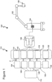
- FIG 1 is a schematic diagram showing a microscope system 100 according to an embodiment.
- the microscope system 100 comprises a surgical microscope 102 typically operated by a surgeon and/or an assistant in an operating room to perform surgery on a patient, such as brain, eye or spine surgery.
- the microscope system 100 further comprises a processor 104 and a memory 106 which may be part of control unit 108.
- the control unit 108 may be formed by a computer device.
- the control unit 108 comprising the processor 104 and the memory 106 is coupled to a user identification unit 110 which is configured to detect a user identification authorizing the user (e.g. a surgeon or nurse) designated by 112 in Figure 1 .
- the user identification unit 110 comprises sensor means e.g. in form of a plurality of sensors 114, 116, 118, 120, 122.
- the user identification unit 110 further comprises identification means e.g. in form of a plurality of interface media 124, 126, 128, 130, 132.
- each of the plurality of sensors 114 to 122 is configured to interact with one of the interface media 124 to 132 as illustrated by arrows P in Figure 1 .
- each interface medium 124 to 132 comprises an identification means which is configured to be recognized by the associated sensor 114 to 122 in order to identify the user before the surgical microscope 102 is put into operation.
- the sensor means formed by the plurality of sensors 114 to 122 provides a physical interface between the control unit 108 on the one hand and the associated interface media 124 to 132 on the other hand.
- the memory 106 is configured to store a plurality of customization profiles. Each of the customization profiles stored in the memory 106 defines at least one predetermined operational setting according to which the surgical microscope 102 operates once the surgical microscope 102 is put into operation after the user 112 has been identified by means of the user identification unit 110. For illustrative purposes only, the different operational settings are referred to with reference sign 134 in Figure 1 .
- the processor 104 is configured to select one of the plurality of customization profiles based on the user identification which is provided by one of the interface media 124 to 132 and detected by the associated sensor 114 to 122. Among the plurality of customization profiles stored in the memory 106, the processor 104 selects the one profile which belongs to the specific user recognized by the user identification. With selecting this customization profile, the user is enabled to operate the surgical microscope 102 in accordance with the operational setting defined by the selected customization profile.
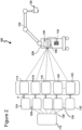
- Figure 2 illustrates a modification of the embodiment shown in Figure 1 .
- the control unit 108 including the processor 104 and the memory 106 is formed by a component physically separated from the surgical microscope
- the modified configuration of Figure 2 includes a control unit 208 which is integrated with the surgical microscope 102.
- the control unit 208 includes the processor 104 and the memory 106.
- the configurations illustrated in Figures 1 and 2 are identical.
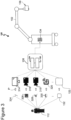
- Figure 3 shows an exemplary configuration which is based on the embodiment of Figure 1 .
- This exemplary configuration shall illustrate which types of sensors and associated interface media may be used to form the sensor means for identifying the user.
- the sensor means of the user identification unit 110 may comprise a touch sensitive screen 314 (corresponding to sensor 114 in Figure 1 ) interacting with a hand or a finger 324 of the user (corresponding to interface medium 124 in Figure 1 ).
- the sensor means may comprise a first camera 316 (corresponding to sensor 116 in Figure 1 ) interacting with a QR code 326 (corresponding to interface medium 126 in Figure 1 ).
- the sensor means may further comprise a second camera 318 (corresponding to sensor 118 in Figure 1 ) interacting with a user's eye 328 (corresponding to interface medium 128 in Figure 1 ).
- the sensor means may further comprise an RFID (contactless) reader 320 (corresponding to sensor 120 in Figure 1 ) interacting with an RFID (contactless) chip 330 (corresponding to interface medium 130 in Figure 1 ).
- sensors 314 to 320 are merely examples, and any other types of sensors and interface media may be used provided that these sensors and interface media are suitable to detect a user identification based on which the specific user can be recognized. Further, it goes without saying that the configuration shown in Figure 3 may also be based on the embodiment of Figure 2 .
- the sensors 114 to 122 and 314 to 320 are illustrated as being physically separated from the surgical microscope 102. However, this illustration serves only to simplify the diagrams. At least two of the sensors 114 to 122, 314 to 320 are integrated with the surgical microscope 102. For example, the camera 318 recognizing the user's eye 328 may be integrated into an eyepiece 136 of the surgical microscope.
- the sensor means shown in Figures 1 to 3 comprises a plurality of sensors 114 to 122, 314 to 320 and associated interface media 124 to 132, 324 to 330.
- the sensor means comprises at least a first sensor and a second sensor, both of which being formed by an RFID chip
- the processor 104 is configured to select a first operational setting if the user input is detected by the first sensor, and to select the second operational setting if the user input is detected by the second sensor.
- the first and second operational settings may be included in a single customization profile belonging to the specific user. Thus, by selecting one of the two RFID readers, the user is enabled to select the corresponding operational setting associated with the selected RFID reader.
- the processor 104 serves to select the customization profile based on an identification of the user 112 and to operate the surgical microscope 102 in accordance with the operational setting which is defined by the selected customization profile.
- the processor 104 may not be limited to the afore-mentioned function.
- the processor 104 may further be configured to provide a setup assistance function guiding the user 112 in a process for creating a specific customization profile according to his or her preferences, this profile being storable in the memory 106.
- the processor 104 may be configured to prompt the user 112 to input customization information.
- the processor 104 may cause a display device (not shown in the Figures) to present questions or options to which the user 112 can respond to in order to create the desired profile.
- the processor 104 may e.g. provide a sequence of queries, each query prompting a user input based on which the customization profile can be created.
- the processor 104 may further be configured to apply a machine learning algorithm. Using such a machine learning algorithm, the processor 104 may create the customization profiles to be stored in the memory 106.
- the processor 104 may also be configured to merge at least two customization profiles, which are assigned to different user information, i.e. to different users, into a common customization profile to be stored in the memory 106.
- Such a configuration has its benefits in case that a team of users is working with the surgical microscope 102, and each user of the team shall have the possibility of using also the profiles of the other users.
- the processor 104 may be configured to detect a user actuation during operation of the surgical microscope 102 in order to modify the customization profile belonging to this user based on the detected user actuation. Also for such a configuration, the processor 104 may advantageously use the machine learning algorithm.
- aspects have been described in the context of an apparatus, it is clear that these aspects also represent a description of the corresponding method, where a block or device corresponds to a method step or a feature of a method step. Analogously, aspects described in the context of a method step also represent a description of a corresponding block or item or feature of a corresponding apparatus.
- Some or all of the method steps may be executed by (or using) a hardware apparatus, like for example, a processor, a microprocessor, a programmable computer or an electronic circuit. In some embodiments, some one or more of the most important method steps may be executed by such an apparatus.
- embodiments of the invention can be implemented in hardware or in software.
- the implementation can be performed using a non-transitory storage medium such as a digital storage medium, for example a floppy disc, a DVD, a Blu-Ray, a CD, a ROM, a PROM, and EPROM, an EEPROM or a FLASH memory, having electronically readable control signals stored thereon, which cooperate (or are capable of cooperating) with a programmable computer system such that the respective method is performed. Therefore, the digital storage medium may be computer readable.
- Some embodiments according to the invention comprise a data carrier having electronically readable control signals, which are capable of cooperating with a programmable computer system, such that the method according to claim 10 is performed on the surgical microscope according to any one of the claims 1 to 9.
- embodiments of the present invention can be implemented as a computer program product with a program code, the program code being operative for performing the method according to claim 10 on the surgical microscope according to any one of the claims 1 to 9 when the computer program product runs on a computer.
- the program code may, for example, be stored on a machine readable carrier.
- an embodiment of the present invention is, therefore, a computer program according to claim 11.
- a further embodiment of the present invention is, therefore, a storage medium (or a data carrier, or a computer-readable medium) comprising, stored thereon, the computer program of claim 11.
- the data carrier, the digital storage medium or the recorded medium are typically tangible and/or non-transitionary.
- a further embodiment of the present invention is an apparatus as described herein comprising a processor and the storage medium.
- a further embodiment of the invention is, therefore, a data stream or a sequence of signals representing the computer program according to claim 11.
- the data stream or the sequence of signals may, for example, be configured to be transferred via a data communication connection, for example, via the internet.
- a further embodiment comprises a processing means, for example, a computer or a programmable logic device, configured to, or adapted to, perform the method according to claim 10 on the surgical microscope according to any one of the claims 1 to 9.
- a processing means for example, a computer or a programmable logic device, configured to, or adapted to, perform the method according to claim 10 on the surgical microscope according to any one of the claims 1 to 9.
- a further embodiment comprises a computer having installed thereon the computer program of claim 11.
- a programmable logic device for example, a field programmable gate array
- a field programmable gate array may cooperate with a microprocessor in order to perform one of the methods described herein.
- the methods are preferably performed by any hardware apparatus.
Landscapes
- Engineering & Computer Science (AREA)
- Physics & Mathematics (AREA)
- Health & Medical Sciences (AREA)
- General Physics & Mathematics (AREA)
- Surgery (AREA)
- Analytical Chemistry (AREA)
- Optics & Photonics (AREA)
- Chemical & Material Sciences (AREA)
- Multimedia (AREA)
- General Health & Medical Sciences (AREA)
- Life Sciences & Earth Sciences (AREA)
- Theoretical Computer Science (AREA)
- Medical Informatics (AREA)
- Biomedical Technology (AREA)
- Computer Vision & Pattern Recognition (AREA)
- Public Health (AREA)
- Heart & Thoracic Surgery (AREA)
- Software Systems (AREA)
- Oral & Maxillofacial Surgery (AREA)
- Nuclear Medicine, Radiotherapy & Molecular Imaging (AREA)
- Molecular Biology (AREA)
- Animal Behavior & Ethology (AREA)
- Pathology (AREA)
- Veterinary Medicine (AREA)
- Human Computer Interaction (AREA)
- Business, Economics & Management (AREA)
- Evolutionary Computation (AREA)
- Artificial Intelligence (AREA)
- Computing Systems (AREA)
- General Engineering & Computer Science (AREA)
- Mathematical Physics (AREA)
- Data Mining & Analysis (AREA)
- General Business, Economics & Management (AREA)
- Epidemiology (AREA)
- Primary Health Care (AREA)
- Microscoopes, Condenser (AREA)
- User Interface Of Digital Computer (AREA)
- Medical Treatment And Welfare Office Work (AREA)
Claims (11)
- Mikroskopsystem (100), umfassend:ein Operationsmikroskop (102),einen Speicher (106), der konfiguriert ist, eine Vielzahl von Anpassungsprofilen zu speichern, wobei jedes Anpassungsprofil mindestens eine vorbestimmte Betriebseinstellung (134) definiert,eine Benutzeridentifikationseinheit (110), die konfiguriert ist, eine Benutzeridentifikation zu erkennen, undeinen Prozessor (104), der konfiguriert ist, eines der Vielzahl von Anpassungsprofilen basierend auf der erkannten Benutzeridentifikation auszuwählen und das Operationsmikroskop (102) gemäß der mindestens einen vorbestimmten Betriebseinstellung (134), die durch das ausgewählte Anpassungsprofil definiert ist, zu betreiben,wobei die Benutzeridentifikationseinheit (106) einen oder mehrere Sensoren (114-122, 324-330) umfasst, die konfiguriert sind, die Benutzeridentifikation zu erkennen,die Sensoren (114-122, 324-330) mindestens einen ersten Sensor und einen zweiten Sensor umfassen, die in das Operationsmikroskop (102) integriert sind,mindestens eines der Vielzahl von Anpassungsprofilen mindestens eine erste Betriebseinstellung und eine zweite Betriebseinstellung einschließt,der Prozessor (104) konfiguriert ist, die erste Betriebseinstellung auszuwählen, wenn die Benutzereingabe durch den ersten Sensor erkannt wird, undder Prozessor (104) konfiguriert ist, die zweite Betriebseinstellung auszuwählen, wenn die Benutzereingabe durch den zweiten Sensor erkannt wird.
- Mikroskopsystem (100) nach Anspruch 1, wobei der Prozessor (104) konfiguriert ist, mindestens eines der Vielzahl von Anpassungsprofilen zu erstellen, indem er eine Benutzereingabe einschließend Anpassungsinformationen auffordert.
- Mikroskopsystem (100) nach Anspruch 1 oder 2, wobei der Prozessor (104) konfiguriert ist, eine Sequenz von Abfragen bereitzustellen, wobei jede Abfrage die Benutzereingabe auffordert.
- Mikroskopsystem (100) nach einem der vorstehenden Ansprüche, wobei der eine oder die mehreren Sensoren mindestens einen Sensor umfassen, der aus einer Gruppe einschließend einen Funkfrequenzidentifikationssensor (318), einen Codeleser (316), einen optischen Sensor (318), ein Mikrofon, einen taktilen Sensor (314), eine Kamera (316, 318) und einen berührungsempfindlichen Bildschirm (314) ausgewählt ist.
- Mikroskopsystem (100) nach einem der vorstehenden Ansprüche, wobei der eine oder die mehreren Sensoren ein optisches Augenerkennungsmittel (318) umfassen.
- Mikroskopsystem (100) nach Anspruch 5, wobei das optische Augenerkennungsmittel in einem optischen Okular (136) des Operationsmikroskops (102) eingeschlossen ist.
- Mikroskopsystem (100) nach einem der vorstehenden Ansprüche, wobei der Prozessor (104) konfiguriert ist, mindestens eines der Vielzahl von Anpassungsprofilen basierend auf einem Maschinenlernalgorithmus zu erstellen.
- Mikroskopsystem (100) nach einem der vorstehenden Ansprüche, wobei der Prozessor (104) konfiguriert ist, mindestens zwei der Vielzahl von Anpassungsprofilen, die verschiedenen Benutzerinformationen zugewiesen sind, zu einem gemeinsamen Anpassungsprofil zusammenzuführen.
- Mikroskopsystem (100) nach einem der vorstehenden Ansprüche, wobei der Prozessor (104) konfiguriert ist, eine Benutzerbetätigung während des Betriebs des Operationsmikroskops (102) zu erkennen und das mindestens eine der Vielzahl von Anpassungsprofilen basierend auf der erkannten Benutzerbetätigung zu modifizieren.
- Verfahren zum Steuern eines Operationsmikroskops (102), umfassend die folgenden Schritte:Bereitstellen einer Vielzahl von Anpassungsprofilen, wobei jedes Anpassungsprofil mindestens eine vorbestimmte Betriebseinstellung (134) definiert, wobei mindestens eines der Vielzahl von Anpassungsprofilen mindestens eine erste Betriebseinstellung und eine zweite Betriebseinstellung einschließt,Erkennen einer Benutzeridentifikation mit einem ersten Sensor, der in das Operationsmikroskop (102) integriert ist, oder einem zweiten Sensor, der in das Operationsmikroskop (102) integriert ist,Auswählen eines der Vielzahl von Anpassungsprofilen basierend auf der erkannten Benutzeridentifikation,Auswählen der ersten Betriebseinstellung, wenn der Benutzer durch den ersten Sensor erkannt wird,Auswählen der zweiten Betriebseinstellung, wenn der Benutzer durch den zweiten Sensor erkannt wird, undBetreiben des Operationsmikroskops (102) gemäß der ausgewählten Betriebseinstellung (134), die durch das ausgewählte Anpassungsprofil definiert ist.
- Computerprogramm mit einem Programmcode zum Veranlassen eines Operationsmikroskops (102) nach einem der Ansprüche 1 bis 9, das Verfahren nach Anspruch 10 durchzuführen, wenn das Computerprogramm auf einem Prozessor (104) durchgeführt wird.
Priority Applications (4)
| Application Number | Priority Date | Filing Date | Title |
|---|---|---|---|
| EP19176723.5A EP3744285B1 (de) | 2019-05-27 | 2019-05-27 | Mikroskopsystem und verfahren zur steuerung eines chirurgischen mikroskops |
| JP2020090948A JP6926278B2 (ja) | 2019-05-27 | 2020-05-25 | 顕微鏡システムおよび手術用顕微鏡を制御するための方法 |
| US15/929,867 US11536938B2 (en) | 2019-05-27 | 2020-05-27 | Microscope system and method for controlling a surgical microscope |
| CN202010460227.XA CN112002405A (zh) | 2019-05-27 | 2020-05-27 | 显微镜系统和用于控制手术显微镜的方法 |
Applications Claiming Priority (1)
| Application Number | Priority Date | Filing Date | Title |
|---|---|---|---|
| EP19176723.5A EP3744285B1 (de) | 2019-05-27 | 2019-05-27 | Mikroskopsystem und verfahren zur steuerung eines chirurgischen mikroskops |
Publications (2)
| Publication Number | Publication Date |
|---|---|
| EP3744285A1 EP3744285A1 (de) | 2020-12-02 |
| EP3744285B1 true EP3744285B1 (de) | 2024-11-27 |
Family
ID=66655225
Family Applications (1)
| Application Number | Title | Priority Date | Filing Date |
|---|---|---|---|
| EP19176723.5A Active EP3744285B1 (de) | 2019-05-27 | 2019-05-27 | Mikroskopsystem und verfahren zur steuerung eines chirurgischen mikroskops |
Country Status (4)
| Country | Link |
|---|---|
| US (1) | US11536938B2 (de) |
| EP (1) | EP3744285B1 (de) |
| JP (1) | JP6926278B2 (de) |
| CN (1) | CN112002405A (de) |
Families Citing this family (3)
| Publication number | Priority date | Publication date | Assignee | Title |
|---|---|---|---|---|
| DE102020108345A1 (de) * | 2020-03-26 | 2021-09-30 | Carl Zeiss Meditec Ag | Einlesen von Codes mittels Operationsmikroskop-Kamera |
| EP4509080A3 (de) * | 2021-03-24 | 2025-05-21 | Leica Instruments (Singapore) Pte. Ltd. | Operationsmikroskopsystem und entsprechendes system, verfahren und computerprogramm für ein operationsmikroskopsystem |
| DE102021204031A1 (de) | 2021-04-22 | 2022-10-27 | Carl Zeiss Meditec Ag | Verfahren zum Betreiben eines Operationsmikroskops und Operationsmikroskop |
Citations (1)
| Publication number | Priority date | Publication date | Assignee | Title |
|---|---|---|---|---|
| DE102008043534A1 (de) * | 2008-11-06 | 2010-05-12 | Carl Zeiss Surgical Gmbh | Zentrale Gerätesteuerung im Operationssaal |
Family Cites Families (14)
| Publication number | Priority date | Publication date | Assignee | Title |
|---|---|---|---|---|
| ES2222518T3 (es) * | 1996-08-29 | 2005-02-01 | BAUSCH & LOMB INCORPORATED | Control de frecuencia y de potencia de dos bucles. |
| JP2003530938A (ja) * | 2000-04-26 | 2003-10-21 | ジーイー・メディカル・システムズ・グローバル・テクノロジー・カンパニー・エルエルシー | 医療装置のユーザカスタム化のオートメーション化 |
| DE10349419B4 (de) * | 2003-10-17 | 2006-10-12 | Carl Zeiss Surgical Gmbh | Verfahren zum automatischen Einstellen mindestens eines Geräteparameters eines medizinischen Gerätes, medizinisches Gerät und medizinisches System |
| CN103491848B (zh) * | 2011-12-26 | 2015-10-07 | 奥林巴斯医疗株式会社 | 医疗用内窥镜系统 |
| US20140063219A1 (en) * | 2012-08-28 | 2014-03-06 | General Electric Company | System and method including a portable user profile for medical imaging systems |
| CN104379096B (zh) * | 2013-06-14 | 2016-09-21 | 视乐有限公司 | 用于定制屈光手术的自动机器设置 |
| JP6574939B2 (ja) * | 2014-09-16 | 2019-09-18 | ソニー株式会社 | 表示制御装置、表示制御方法、表示制御システムおよび頭部装着ディスプレイ |
| EP3289540A1 (de) * | 2015-04-29 | 2018-03-07 | Koninklijke Philips N.V. | Verfahren und vorrichtung zum betrieb einer vorrichtung durch mitglieder einer gruppe |
| FR3043512B1 (fr) * | 2015-11-05 | 2017-11-17 | Continental Automotive France | Dispositif de detection bidirectionnelle d'approche d'un equipement portable d'acces main libre a un vehicule et procede de detection associe |
| US10426339B2 (en) * | 2016-01-13 | 2019-10-01 | Novartis Ag | Apparatuses and methods for parameter adjustment in surgical procedures |
| EP3266403B1 (de) * | 2016-03-30 | 2020-04-15 | Sony Corporation | Steuerungsvorrichtung, steuerungsverfahren und betrieb einer mikroskopvorrichtung |
| JP2018105974A (ja) * | 2016-12-26 | 2018-07-05 | ソニー株式会社 | 手術用ルーペ |
| US10554780B2 (en) * | 2017-02-24 | 2020-02-04 | Samsung Electronics Co., Ltd. | System and method for automated personalization of an environment |
| CN111225639B (zh) * | 2017-10-17 | 2022-10-18 | 爱尔康公司 | 自定义眼科手术轮廓 |
-
2019
- 2019-05-27 EP EP19176723.5A patent/EP3744285B1/de active Active
-
2020
- 2020-05-25 JP JP2020090948A patent/JP6926278B2/ja active Active
- 2020-05-27 US US15/929,867 patent/US11536938B2/en active Active
- 2020-05-27 CN CN202010460227.XA patent/CN112002405A/zh active Pending
Patent Citations (1)
| Publication number | Priority date | Publication date | Assignee | Title |
|---|---|---|---|---|
| DE102008043534A1 (de) * | 2008-11-06 | 2010-05-12 | Carl Zeiss Surgical Gmbh | Zentrale Gerätesteuerung im Operationssaal |
Also Published As
| Publication number | Publication date |
|---|---|
| US20200409129A1 (en) | 2020-12-31 |
| JP6926278B2 (ja) | 2021-08-25 |
| CN112002405A (zh) | 2020-11-27 |
| JP2020192324A (ja) | 2020-12-03 |
| EP3744285A1 (de) | 2020-12-02 |
| US11536938B2 (en) | 2022-12-27 |
Similar Documents
| Publication | Publication Date | Title |
|---|---|---|
| US11536938B2 (en) | Microscope system and method for controlling a surgical microscope | |
| CN104950702B (zh) | 通过生物认证来判别操作员的机器人系统 | |
| DK2996015T3 (en) | PROCEDURE TO USE IMPROVED REALITY AS HMI VIEW | |
| US8270729B2 (en) | Image authenticating apparatus, image authenticating method, recording medium, electronic device, and circuit substrate | |
| EP2525271B1 (de) | Verfahren und Vorrichtung zur Verarbeitung der Eingabe in einem mobilen Endgerät | |
| CN109230927B (zh) | 电梯的控制方法、装置、计算机设备及存储介质 | |
| US20180130556A1 (en) | Method of and apparatus for operating a device by members of a group | |
| US20100183199A1 (en) | Systems and methods for biometric identification | |
| US20070211915A1 (en) | Gesture activated home appliance | |
| US11978284B2 (en) | Authentication data generation device, authentication device, authentication data generation method, and recording medium | |
| JP2010108070A (ja) | ユーザインタフェース制御装置、ユーザインタフェース制御方法およびプログラム | |
| US20210369391A1 (en) | Microscope system and method for controlling a surgical microscope | |
| EP4223250A1 (de) | Operationsmikroskopsystem und system, verfahren und computerprogramm für ein mikroskop eines operationsmikroskopsystems | |
| EP3173899A1 (de) | Anzeigevorrichtung und -verfahren zur benachrichtigung der position einer authentifizierungsvorrichtung in einem anzeigebereich | |
| US10354242B2 (en) | Scanner gesture recognition | |
| EP3416347A1 (de) | Verfahren zum einstellen der daten einer vorrichtung zur analyse von körperinformationen | |
| CN109508587A (zh) | 身体信息分析装置及其底妆分析方法 | |
| CN107340962B (zh) | 基于虚拟现实设备的输入方法、装置及虚拟现实设备 | |
| CN110574031A (zh) | 用于电子设备的登记方案 | |
| JP2009205203A (ja) | 虹彩認証装置 | |
| WO2022009802A1 (ja) | 操作システム、処理システム、操作方法、プログラム、及び記憶媒体 | |
| CN112702482B (zh) | 一种摄像头调节焦距的方法以及装置 | |
| KR20180000974A (ko) | 터치스크린 장치 및 그 지문 인식 방법 | |
| CN113885710A (zh) | 智能设备的控制方法、控制装置及智能系统 | |
| JP6345502B2 (ja) | 医用画像診断装置 |
Legal Events
| Date | Code | Title | Description |
|---|---|---|---|
| PUAI | Public reference made under article 153(3) epc to a published international application that has entered the european phase |
Free format text: ORIGINAL CODE: 0009012 |
|
| STAA | Information on the status of an ep patent application or granted ep patent |
Free format text: STATUS: THE APPLICATION HAS BEEN PUBLISHED |
|
| AK | Designated contracting states |
Kind code of ref document: A1 Designated state(s): AL AT BE BG CH CY CZ DE DK EE ES FI FR GB GR HR HU IE IS IT LI LT LU LV MC MK MT NL NO PL PT RO RS SE SI SK SM TR |
|
| AX | Request for extension of the european patent |
Extension state: BA ME |
|
| STAA | Information on the status of an ep patent application or granted ep patent |
Free format text: STATUS: REQUEST FOR EXAMINATION WAS MADE |
|
| 17P | Request for examination filed |
Effective date: 20210601 |
|
| RBV | Designated contracting states (corrected) |
Designated state(s): AL AT BE BG CH CY CZ DE DK EE ES FI FR GB GR HR HU IE IS IT LI LT LU LV MC MK MT NL NO PL PT RO RS SE SI SK SM TR |
|
| STAA | Information on the status of an ep patent application or granted ep patent |
Free format text: STATUS: EXAMINATION IS IN PROGRESS |
|
| 17Q | First examination report despatched |
Effective date: 20220908 |
|
| P01 | Opt-out of the competence of the unified patent court (upc) registered |
Effective date: 20230414 |
|
| GRAP | Despatch of communication of intention to grant a patent |
Free format text: ORIGINAL CODE: EPIDOSNIGR1 |
|
| STAA | Information on the status of an ep patent application or granted ep patent |
Free format text: STATUS: GRANT OF PATENT IS INTENDED |
|
| RIC1 | Information provided on ipc code assigned before grant |
Ipc: G06V 40/10 20220101ALI20240607BHEP Ipc: G02B 21/36 20060101ALI20240607BHEP Ipc: G02B 21/00 20060101ALI20240607BHEP Ipc: A61B 90/20 20160101AFI20240607BHEP |
|
| INTG | Intention to grant announced |
Effective date: 20240624 |
|
| GRAS | Grant fee paid |
Free format text: ORIGINAL CODE: EPIDOSNIGR3 |
|
| GRAA | (expected) grant |
Free format text: ORIGINAL CODE: 0009210 |
|
| STAA | Information on the status of an ep patent application or granted ep patent |
Free format text: STATUS: THE PATENT HAS BEEN GRANTED |
|
| AK | Designated contracting states |
Kind code of ref document: B1 Designated state(s): AL AT BE BG CH CY CZ DE DK EE ES FI FR GB GR HR HU IE IS IT LI LT LU LV MC MK MT NL NO PL PT RO RS SE SI SK SM TR |
|
| REG | Reference to a national code |
Ref country code: GB Ref legal event code: FG4D |
|
| REG | Reference to a national code |
Ref country code: CH Ref legal event code: EP |
|
| REG | Reference to a national code |
Ref country code: IE Ref legal event code: FG4D |
|
| REG | Reference to a national code |
Ref country code: DE Ref legal event code: R096 Ref document number: 602019062478 Country of ref document: DE |
|
| REG | Reference to a national code |
Ref country code: LT Ref legal event code: MG9D |
|
| REG | Reference to a national code |
Ref country code: NL Ref legal event code: MP Effective date: 20241127 |
|
| PG25 | Lapsed in a contracting state [announced via postgrant information from national office to epo] |
Ref country code: HR Free format text: LAPSE BECAUSE OF FAILURE TO SUBMIT A TRANSLATION OF THE DESCRIPTION OR TO PAY THE FEE WITHIN THE PRESCRIBED TIME-LIMIT Effective date: 20241127 Ref country code: IS Free format text: LAPSE BECAUSE OF FAILURE TO SUBMIT A TRANSLATION OF THE DESCRIPTION OR TO PAY THE FEE WITHIN THE PRESCRIBED TIME-LIMIT Effective date: 20250327 Ref country code: PT Free format text: LAPSE BECAUSE OF FAILURE TO SUBMIT A TRANSLATION OF THE DESCRIPTION OR TO PAY THE FEE WITHIN THE PRESCRIBED TIME-LIMIT Effective date: 20250327 |
|
| PG25 | Lapsed in a contracting state [announced via postgrant information from national office to epo] |
Ref country code: FI Free format text: LAPSE BECAUSE OF FAILURE TO SUBMIT A TRANSLATION OF THE DESCRIPTION OR TO PAY THE FEE WITHIN THE PRESCRIBED TIME-LIMIT Effective date: 20241127 Ref country code: NL Free format text: LAPSE BECAUSE OF FAILURE TO SUBMIT A TRANSLATION OF THE DESCRIPTION OR TO PAY THE FEE WITHIN THE PRESCRIBED TIME-LIMIT Effective date: 20241127 |
|
| REG | Reference to a national code |
Ref country code: AT Ref legal event code: MK05 Ref document number: 1744972 Country of ref document: AT Kind code of ref document: T Effective date: 20241127 |
|
| PG25 | Lapsed in a contracting state [announced via postgrant information from national office to epo] |
Ref country code: BG Free format text: LAPSE BECAUSE OF FAILURE TO SUBMIT A TRANSLATION OF THE DESCRIPTION OR TO PAY THE FEE WITHIN THE PRESCRIBED TIME-LIMIT Effective date: 20241127 |
|
| PG25 | Lapsed in a contracting state [announced via postgrant information from national office to epo] |
Ref country code: ES Free format text: LAPSE BECAUSE OF FAILURE TO SUBMIT A TRANSLATION OF THE DESCRIPTION OR TO PAY THE FEE WITHIN THE PRESCRIBED TIME-LIMIT Effective date: 20241127 |
|
| PG25 | Lapsed in a contracting state [announced via postgrant information from national office to epo] |
Ref country code: NO Free format text: LAPSE BECAUSE OF FAILURE TO SUBMIT A TRANSLATION OF THE DESCRIPTION OR TO PAY THE FEE WITHIN THE PRESCRIBED TIME-LIMIT Effective date: 20250227 |
|
| PG25 | Lapsed in a contracting state [announced via postgrant information from national office to epo] |
Ref country code: LV Free format text: LAPSE BECAUSE OF FAILURE TO SUBMIT A TRANSLATION OF THE DESCRIPTION OR TO PAY THE FEE WITHIN THE PRESCRIBED TIME-LIMIT Effective date: 20241127 Ref country code: AT Free format text: LAPSE BECAUSE OF FAILURE TO SUBMIT A TRANSLATION OF THE DESCRIPTION OR TO PAY THE FEE WITHIN THE PRESCRIBED TIME-LIMIT Effective date: 20241127 Ref country code: GR Free format text: LAPSE BECAUSE OF FAILURE TO SUBMIT A TRANSLATION OF THE DESCRIPTION OR TO PAY THE FEE WITHIN THE PRESCRIBED TIME-LIMIT Effective date: 20250228 |
|
| PG25 | Lapsed in a contracting state [announced via postgrant information from national office to epo] |
Ref country code: PL Free format text: LAPSE BECAUSE OF FAILURE TO SUBMIT A TRANSLATION OF THE DESCRIPTION OR TO PAY THE FEE WITHIN THE PRESCRIBED TIME-LIMIT Effective date: 20241127 |
|
| PG25 | Lapsed in a contracting state [announced via postgrant information from national office to epo] |
Ref country code: RS Free format text: LAPSE BECAUSE OF FAILURE TO SUBMIT A TRANSLATION OF THE DESCRIPTION OR TO PAY THE FEE WITHIN THE PRESCRIBED TIME-LIMIT Effective date: 20250227 |
|
| PG25 | Lapsed in a contracting state [announced via postgrant information from national office to epo] |
Ref country code: SM Free format text: LAPSE BECAUSE OF FAILURE TO SUBMIT A TRANSLATION OF THE DESCRIPTION OR TO PAY THE FEE WITHIN THE PRESCRIBED TIME-LIMIT Effective date: 20241127 |
|
| PGFP | Annual fee paid to national office [announced via postgrant information from national office to epo] |
Ref country code: DE Payment date: 20250528 Year of fee payment: 7 |
|
| PG25 | Lapsed in a contracting state [announced via postgrant information from national office to epo] |
Ref country code: DK Free format text: LAPSE BECAUSE OF FAILURE TO SUBMIT A TRANSLATION OF THE DESCRIPTION OR TO PAY THE FEE WITHIN THE PRESCRIBED TIME-LIMIT Effective date: 20241127 |
|
| PGFP | Annual fee paid to national office [announced via postgrant information from national office to epo] |
Ref country code: GB Payment date: 20250520 Year of fee payment: 7 |
|
| PG25 | Lapsed in a contracting state [announced via postgrant information from national office to epo] |
Ref country code: EE Free format text: LAPSE BECAUSE OF FAILURE TO SUBMIT A TRANSLATION OF THE DESCRIPTION OR TO PAY THE FEE WITHIN THE PRESCRIBED TIME-LIMIT Effective date: 20241127 |
|
| PGFP | Annual fee paid to national office [announced via postgrant information from national office to epo] |
Ref country code: FR Payment date: 20250526 Year of fee payment: 7 |
|
| PG25 | Lapsed in a contracting state [announced via postgrant information from national office to epo] |
Ref country code: RO Free format text: LAPSE BECAUSE OF FAILURE TO SUBMIT A TRANSLATION OF THE DESCRIPTION OR TO PAY THE FEE WITHIN THE PRESCRIBED TIME-LIMIT Effective date: 20241127 |
|
| PG25 | Lapsed in a contracting state [announced via postgrant information from national office to epo] |
Ref country code: SK Free format text: LAPSE BECAUSE OF FAILURE TO SUBMIT A TRANSLATION OF THE DESCRIPTION OR TO PAY THE FEE WITHIN THE PRESCRIBED TIME-LIMIT Effective date: 20241127 |
|
| PG25 | Lapsed in a contracting state [announced via postgrant information from national office to epo] |
Ref country code: CZ Free format text: LAPSE BECAUSE OF FAILURE TO SUBMIT A TRANSLATION OF THE DESCRIPTION OR TO PAY THE FEE WITHIN THE PRESCRIBED TIME-LIMIT Effective date: 20241127 |
|
| PG25 | Lapsed in a contracting state [announced via postgrant information from national office to epo] |
Ref country code: IT Free format text: LAPSE BECAUSE OF FAILURE TO SUBMIT A TRANSLATION OF THE DESCRIPTION OR TO PAY THE FEE WITHIN THE PRESCRIBED TIME-LIMIT Effective date: 20241127 |
|
| REG | Reference to a national code |
Ref country code: DE Ref legal event code: R097 Ref document number: 602019062478 Country of ref document: DE |
|
| PG25 | Lapsed in a contracting state [announced via postgrant information from national office to epo] |
Ref country code: SE Free format text: LAPSE BECAUSE OF FAILURE TO SUBMIT A TRANSLATION OF THE DESCRIPTION OR TO PAY THE FEE WITHIN THE PRESCRIBED TIME-LIMIT Effective date: 20241127 |
|
| PLBE | No opposition filed within time limit |
Free format text: ORIGINAL CODE: 0009261 |
|
| STAA | Information on the status of an ep patent application or granted ep patent |
Free format text: STATUS: NO OPPOSITION FILED WITHIN TIME LIMIT |
|
| 26N | No opposition filed |
Effective date: 20250828 |