EP3744164B1 - Cutting assembly for an agricultural or forestry cutting device - Google Patents
Cutting assembly for an agricultural or forestry cutting device Download PDFInfo
- Publication number
- EP3744164B1 EP3744164B1 EP19177104.7A EP19177104A EP3744164B1 EP 3744164 B1 EP3744164 B1 EP 3744164B1 EP 19177104 A EP19177104 A EP 19177104A EP 3744164 B1 EP3744164 B1 EP 3744164B1
- Authority
- EP
- European Patent Office
- Prior art keywords
- cutting
- knife
- assembly according
- cutting assembly
- edge
- Prior art date
- Legal status (The legal status is an assumption and is not a legal conclusion. Google has not performed a legal analysis and makes no representation as to the accuracy of the status listed.)
- Active
Links
- 238000005520 cutting process Methods 0.000 title claims description 98
- 230000001154 acute effect Effects 0.000 claims description 3
- 239000000463 material Substances 0.000 description 7
- 244000025254 Cannabis sativa Species 0.000 description 4
- 241000196324 Embryophyta Species 0.000 description 4
- 230000013011 mating Effects 0.000 description 2
- 241000233866 Fungi Species 0.000 description 1
- 229910000760 Hardened steel Inorganic materials 0.000 description 1
- 241001124569 Lycaenidae Species 0.000 description 1
- 230000000712 assembly Effects 0.000 description 1
- 238000000429 assembly Methods 0.000 description 1
- 230000001419 dependent effect Effects 0.000 description 1
- 238000011161 development Methods 0.000 description 1
- 230000018109 developmental process Effects 0.000 description 1
- 238000003306 harvesting Methods 0.000 description 1
- 230000035515 penetration Effects 0.000 description 1
- 238000010008 shearing Methods 0.000 description 1
- 235000013311 vegetables Nutrition 0.000 description 1
Images
Classifications
-
- A—HUMAN NECESSITIES
- A01—AGRICULTURE; FORESTRY; ANIMAL HUSBANDRY; HUNTING; TRAPPING; FISHING
- A01D—HARVESTING; MOWING
- A01D34/00—Mowers; Mowing apparatus of harvesters
- A01D34/01—Mowers; Mowing apparatus of harvesters characterised by features relating to the type of cutting apparatus
- A01D34/02—Mowers; Mowing apparatus of harvesters characterised by features relating to the type of cutting apparatus having reciprocating cutters
- A01D34/13—Cutting apparatus
- A01D34/14—Knife-bars
-
- A—HUMAN NECESSITIES
- A01—AGRICULTURE; FORESTRY; ANIMAL HUSBANDRY; HUNTING; TRAPPING; FISHING
- A01D—HARVESTING; MOWING
- A01D34/00—Mowers; Mowing apparatus of harvesters
- A01D34/01—Mowers; Mowing apparatus of harvesters characterised by features relating to the type of cutting apparatus
- A01D34/02—Mowers; Mowing apparatus of harvesters characterised by features relating to the type of cutting apparatus having reciprocating cutters
- A01D34/13—Cutting apparatus
- A01D34/18—Guard fingers; Ledger-plates
Definitions
- the invention relates to a cutting arrangement for an agricultural or forestry cutter, comprising: a lower part and an upper part which together form at least one finger which extends along a longitudinal axis, a blade gap being formed between the lower part and the upper part, a knife which is guided back and forth in the blade gap in a drive direction transversely to the longitudinal axis and which has at least one cutting edge.
- Cutting assemblies are known, for example, in mowers, which usually have a finger bar on which several fingers are arranged. A knife is guided in an oscillating manner relative to the finger bar, the knife comprising a knife rail to which a plurality of knife blades are attached. The knife blades form cutting edges that work together with shearbars formed by the mowing fingers.
- a corresponding mowing finger arrangement is in the publication EP 2 366 274 A2 described.
- the US 196107A describes a cutting or mowing mechanism with a mowing finger, in which a blade gap is formed, with a knife being guided back and forth in the blade gap, which has a cutting edge which has a lower cutting bevel and an upper cutting bevel.
- the DE 32 29 743 A1 shows a finger bar mower for harvesting machines with a reciprocating mowing knife made of knife blades arranged on a knife bar, which interact with the mowing fingers as counter-blades.
- a lower part and an upper part together form a mowing finger, with a blade gap being formed between the lower part and the upper part.
- the knife blades have a cutting edge which has a cutting bevel facing the upper part.
- the lower part is in two parts executed, wherein a guide part and a carrier together form the lower part and the guide part is arranged in sections between carrier and upper part.
- the U.S. 1,945,301 A refers to a blade guard of mowers and harvesters.
- the guard finger has an upper, rearwardly extending shield which serves to protect the knife blade and to provide an upper edge on each side against which the grass can rest under the action of the knives.
- the blade is provided with serrations on its side edges forming teeth which engage the grass or the like to ensure the grass or the like is held in the correct position for shearing.
- the U.S. 2002/005035 A1 relates to a mowing finger for an agricultural mowing machine of the kind commonly used in grass, grain and vegetable cutting machines, having two equal and parallel juxtaposed fingers formed by two superimposed hardened steel plates which are spaced in their rear and central portions exhibit. The front areas are connected, forming sharp points that curve upwards. A cutting gap is formed in the central portions to allow for the oscillating movement of the cutting blades, the blades of which act with serrated side edges to produce the shear cuts.
- a disadvantage of the cutting arrangements provided for mowing or for cutting crops is that they are limited to cutting stalks.
- An object of the invention is to provide a cutting arrangement which allows cutting of plant parts with greater strength and/or hardness.
- the cutting arrangement according to the invention for an agricultural or forestry cutter comprises a lower part and an upper part which together form at least one finger which extends along a longitudinal axis, with a blade gap being formed between the lower part and the upper part, and a knife which is Blade gap is guided back and forth in a drive direction transverse to the longitudinal axis and which has at least one cutting edge.
- the cutting edge has a lower cutting bevel facing the lower part and an upper cutting bevel facing the upper part.
- the cutting edge does not work together with a counter blade at the blade gap.
- the cutting edge therefore does not perform a scissor cut in conjunction with the finger.
- the finger advantageously serves as a counter-holder and the knife cuts through the material to be cut in the manner of a wedge cut or ax cut by means of the cutting edge with the lower cutting bevel and the upper cutting bevel. This allows clippings of greater thickness and strength to be cut through, such as branches.
- the lower cutting bevel and the upper cutting bevel preferably meet at a cutting edge and preferably enclose an acute cutting edge angle.
- the designations lower part and upper part do not refer to a specific orientation of the cutterbar in relation to a ground or a working machine, but only define top and bottom with regard to the cutterbar itself.
- the longitudinal axis of the finger extends in a Cartesian coordinate system with three spatial directions X, Y and Z in the X-direction, while the driving direction of the knife is in particular in the Z-direction.
- the bottom and the top are spaced apart in the Y-direction.
- the designations of components as upper and lower components are spaced apart in the Y-direction, with the upper components being located closer to the top than the bottom and with the bottom components being located closer to the bottom than the top.
- the part of the material to be cut is on the side of the upper part when cutting.
- the knife has a lower contact surface facing the lower part, to which the lower cutting bevel is arranged running at an angle, and that the knife has an upper contact surface facing the upper part, to which the upper cutting bevel is arranged running at an angle.
- the lower contact surface and the upper contact surface are preferably arranged parallel to one another.
- the cutting edge is preferably arranged in a thickness direction of the blade between the lower contact surface and the upper contact surface.
- the lower part is designed in two parts, with a guide part and a carrier together forming the lower part and with the guide part being arranged at least in sections between the carrier and the upper part.
- the guide part has a lower guide surface that delimits the knife gap and the upper part has an upper guide surface that also delimits the knife gap, the lower guide surface and the upper guide surface being arranged parallel to one another.
- the guide part has at least one lower counter-edge and the upper part has at least one upper counter-edge, which the cutting edge is guided past during the reciprocating movement of the knife, the upper counter-edge being toothed and the lower counter-edge being straight.
- the guide part preferably has lower mating edges on both sides of the longitudinal axis and the upper part has upper mating edges on both sides of the longitudinal axis.
- the lower part and the upper part form two or more fingers, the fingers being arranged parallel to one another and via at least one web on the lower part and/or on the upper part are connected to each other.
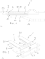
- the cutting assembly according to the invention for an agricultural or forestry cutter comprises a lower part 2 and an upper part 3, which together form at least one finger 1, the extends along a longitudinal axis.
- the lower part 2 and the upper part 3 form two fingers 1, the fingers 1 being arranged parallel to one another and connected to one another via at least one web 21 on the lower part 2 and/or on the upper part 3.
- This embodiment is also called double finger.
- two webs 21 are provided on the upper part 3 and one web 21 on the lower part 2, as in FIG figure 2 is recognizable.
- the lower part 2 and the upper part 3 are connected to one another at the tips 20 of the fingers 1 .
- the arrangement of the finger 1 by means of fastening means on a finger bar (not shown) is known to a person skilled in the art.
- the longitudinal axes of the two fingers 1 (not shown) extend parallel to one another in the X direction in a Cartesian coordinate system with three spatial directions X, Y and Z.
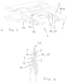
- a blade gap 4 is formed between the lower part 2 and the upper part 3 .
- a knife 5 is guided back and forth in a drive direction transverse to the longitudinal axis.
- the driving direction of the knife corresponds in particular to the Z-direction.
- the bottom part 2 and the top part 3 are spaced apart in the Y-direction.
- the Y-direction corresponds to a thickness direction Y of the blade 5.
- the blade 5 has at least one cutting edge 6, which is described below with reference to FIG Figures 8 to 10 is described in more detail.
- the cutting edge 6 has a lower cutting bevel 7 facing the lower part 2 and an upper cutting bevel 8 facing the upper part 3 .
- the cutting edge 11 does not work together with a shearbar on the blade gap 4.
- the cutting edge 11 therefore does not perform a scissor cut in conjunction with the finger 1.
- the finger 1 serves as a counter-holder and the knife cuts through the material to be cut in the manner of a wedge cut or ax cut using the cutting edge 11. This allows cutting material of greater strength and strength to be severed, for example branches.
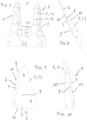
- the knife 5 preferably consists of a plurality of knife blades 22, each of which has at least one cutting edge 6, only one knife blade 22 being shown here.
- the skilled person is the arrangement of several knife blades 22 means Fastening means known on a cutter bar, not shown, to form the knife 5.
- the knife blade 22 preferably has two cutting edges 6 facing away from one another.
- the lower cutting bevel 7 and the upper cutting bevel 8 preferably abut one another at a cutting edge 11 and preferably enclose an acute cutting edge angle.
- the knife 5 has a lower contact surface 9 which faces the lower part 2 and to which the lower cutting bevel 7 is arranged running at an angle.
- An upper contact surface 10 of the blade 5 facing the upper part 3 is arranged at an angle to the upper cutting bevel 8 .
- the lower contact surface 9 and the upper contact surface 10 are preferably arranged parallel to one another.
- the cutting edge 6 is arranged between the lower contact surface 9 and the upper contact surface 10 in the thickness direction Y of the blade 5 .
- the lower bearing surface 9 and the upper bearing surface 10 interact with the blade gap 4, which is described below with reference to FIG Figures 5 to 7 is explained in more detail.
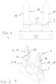
- the lower part 2 is designed in two parts, with a guide part 12 and a carrier 14 forming the lower part 2 together.
- the guide part 12 is arranged in sections between the carrier 14 and the upper part 3 .
- the carrier 14 and the guide part 12 are in particular firmly connected to one another.
- the guide part 12 has a lower guide surface 15 which delimits the blade gap 4 together with an upper guide surface 16 on the upper part 3 .
- the lower guide surface 15 and the upper guide surface 16 are arranged parallel to one another.
- the guide part 12 has at least one lower counter-edge 17 and the upper part 3 has at least one upper counter-edge 18, past which the cutting edge 6 is guided during the reciprocating movement of the knife 5.
- the guide part 12 has four lower counter-edges 17, namely two per finger 1.
- the upper part 3 accordingly has four upper counter-edges 18.
- the upper counter-edges 18 have teeth 19, while the lower counter-edges 17 are straight.
- the toothing 19 advantageously holds the material to be cut during cutting.
- the material to be cut is fanned out by the teeth 19 only in the sections where no special requirements are placed on the cut.
- the part of the clippings remaining on the plant is advantageously given a clean cut by the straight counter-edges 17, as a result of which regrowth and/or penetration of fungi is prevented.
Description
Die Erfindung betrifft eine Schneidanordnung für ein land- oder forstwirtschaftliches Schneidwerk umfassend: ein Unterteil und ein Oberteil, die gemeinsam zumindest einen Finger bilden, der sich entlang einer Längsachse erstreckt, wobei zwischen dem Unterteil und dem Oberteil ein Klingenspalt ausgebildet ist, ein Messer, das in dem Klingenspalt in einer Antriebsrichtung quer zur Längsachse hin und her gehend geführt ist und das zumindest eine Schneide aufweist.The invention relates to a cutting arrangement for an agricultural or forestry cutter, comprising: a lower part and an upper part which together form at least one finger which extends along a longitudinal axis, a blade gap being formed between the lower part and the upper part, a knife which is guided back and forth in the blade gap in a drive direction transversely to the longitudinal axis and which has at least one cutting edge.
Schneidanordnungen sind beispielsweise bei Mähwerken bekannt, die in der Regel einen Fingerbalken aufweisen, an dem mehrere Finger angeordnet sind. Relativ zum Fingerbalken ist ein Messer oszillierend geführt, wobei das Messer eine Messerschiene umfasst, an der mehrere Messerklingen befestigt sind. Die Messerklingen bilden Schneiden, die mit Gegenschneiden, die durch die Mähfinger gebildet sind, zusammenarbeiten. Eine entsprechende Mähfingeranordnung ist in der Druckschrift
Die
Die
Die
Die
Ein Nachteil der zum Mähen beziehungsweise zum Schneiden von Erntegut vorgesehenen Schneidanordnungen besteht darin, dass diese auf das Schneiden von Halmen beschränkt sind.A disadvantage of the cutting arrangements provided for mowing or for cutting crops is that they are limited to cutting stalks.
Eine Aufgabe der Erfindung besteht darin, eine Schneidanordnung anzugeben, welche das Schneiden von Pflanzenteilen mit höherer Stärke und/oder Härte erlaubt.An object of the invention is to provide a cutting arrangement which allows cutting of plant parts with greater strength and/or hardness.
Die Aufgabe wird durch die Schneidanordnung gemäß Anspruch 1 gelöst. In den Unteransprüchen sind vorteilhafte Ausführungsformen und Weiterbildungen angegeben.The object is solved by the cutting arrangement according to
Die erfindungsgemäße Schneidanordnung für ein land- oder forstwirtschaftliches Schneidwerk umfasst ein Unterteil und ein Oberteil, die gemeinsam zumindest einen Finger bilden, der sich entlang einer Längsachse erstreckt, wobei zwischen dem Unterteil und dem Oberteil ein Klingenspalt ausgebildet ist, sowie ein Messer, das in dem Klingenspalt in einer Antriebsrichtung quer zur Längsachse hin und her gehend geführt ist und das zumindest eine Schneide aufweist. Erfindungsgemäß weist die Schneide eine dem Unterteil zugewandte untere Schneidfase und eine dem Oberteil zugewandte obere Schneidfase auf.The cutting arrangement according to the invention for an agricultural or forestry cutter comprises a lower part and an upper part which together form at least one finger which extends along a longitudinal axis, with a blade gap being formed between the lower part and the upper part, and a knife which is Blade gap is guided back and forth in a drive direction transverse to the longitudinal axis and which has at least one cutting edge. According to the invention, the cutting edge has a lower cutting bevel facing the lower part and an upper cutting bevel facing the upper part.
Im Unterschied zum Stand der Technik arbeitet die Schneide nicht mit einer Gegenschneide an dem Klingenspalt zusammen. Die Schneide vollführt also keinen Scherenschnitt im Zusammenspiel mit dem Finger. Der Finger dient hier statt dessen vorteilhaft als Gegenhalter und das Messer durchtrennt das Schnittgut in der Art eines Keilschnitts oder Axtschnitts mittels der Schneide mit der unteren Schneidfase und der oberen Schneidfase. Dadurch kann Schnittgut höherer Stärke und Festigkeit durchtrennt werden, beispielsweise Äste. Die untere Schneidfase und die obere Schneidfase stoßen vorzugsweise an einer Schneidkante aneinander und schließen bevorzugt einen spitzen Schneidenwinkel ein.In contrast to the prior art, the cutting edge does not work together with a counter blade at the blade gap. The cutting edge therefore does not perform a scissor cut in conjunction with the finger. Instead, the finger advantageously serves as a counter-holder and the knife cuts through the material to be cut in the manner of a wedge cut or ax cut by means of the cutting edge with the lower cutting bevel and the upper cutting bevel. This allows clippings of greater thickness and strength to be cut through, such as branches. The lower cutting bevel and the upper cutting bevel preferably meet at a cutting edge and preferably enclose an acute cutting edge angle.
Die Bezeichnungen Unterteil und Oberteil beziehen sich nicht auf eine bestimmte Ausrichtung des Schneidwerks bezüglich eines Bodens oder einer Arbeitsmaschine, sondern definieren oben und unten nur bezüglich des Schneidwerks selbst. Die Längsachse des Fingers erstreckt sich in einem kartesischen Koordinatensystem mit drei Raumrichtungen X, Y und Z in der X-Richtung, während die Antriebsrichtung des Messers insbesondere in der Z-Richtung liegt. Das Unterteil und das Oberteil sind in der Y-Richtung beabstandet angeordnet. Die Bezeichnungen von Bauteilen als obere und untere Bauteile sind, im Sinne der Erfindung, in der Y-Richtung beabstandet angeordnet, wobei die oberen Bauteile dem Oberteil näher angeordnet sind als dem Unterteil und wobei die unteren Bauteile dem Unterteil näher angeordnet sind als dem Oberteil.The designations lower part and upper part do not refer to a specific orientation of the cutterbar in relation to a ground or a working machine, but only define top and bottom with regard to the cutterbar itself. The longitudinal axis of the finger extends in a Cartesian coordinate system with three spatial directions X, Y and Z in the X-direction, while the driving direction of the knife is in particular in the Z-direction. The bottom and the top are spaced apart in the Y-direction. In the context of the invention, the designations of components as upper and lower components are spaced apart in the Y-direction, with the upper components being located closer to the top than the bottom and with the bottom components being located closer to the bottom than the top.
Bei der Verwendung des Schneidwerks ist vorgesehen, dass das Unterteil dem nach dem Schnitt an der Pflanze verbleibenden Teil des Schneidguts zugewandt ist. Der abzuschneidende Teil des Schneidguts befindet sich beim Schnitt auf der Seite des Oberteils.When using the cutter is provided that the lower part of the facing the part of the cuttings remaining on the plant. The part of the material to be cut is on the side of the upper part when cutting.
Gemäß einer bevorzugten Ausführungsform ist vorgesehen, dass das Messer eine dem Unterteil zugewandte untere Anlagefläche aufweist, zu der die untere Schneidfase winklig verlaufend angeordnet ist und dass das Messer eine dem Oberteil zugewandte obere Anlagefläche aufweist, zu der die obere Schneidfase winklig verlaufend angeordnet ist. Die untere Anlagefläche und die obere Anlagefläche sind vorzugsweise parallel zueinander angeordnet. Die Schneidkante ist weiterhin bevorzugt in einer Dickenrichtung des Messers zwischen der unteren Anlagefläche und der oberen Anlagefläche angeordnet.According to a preferred embodiment, it is provided that the knife has a lower contact surface facing the lower part, to which the lower cutting bevel is arranged running at an angle, and that the knife has an upper contact surface facing the upper part, to which the upper cutting bevel is arranged running at an angle. The lower contact surface and the upper contact surface are preferably arranged parallel to one another. Furthermore, the cutting edge is preferably arranged in a thickness direction of the blade between the lower contact surface and the upper contact surface.
Erfindungsgemäß ist vorgesehen, dass das Unterteil zweiteilig ausgeführt ist, wobei ein Führungsteil und ein Träger gemeinsam das Unterteil bilden und wobei das Führungsteil zumindest abschnittsweise zwischen dem Träger und dem Oberteil angeordnet ist. Das Führungsteil weist insbesondere eine untere Führungsfläche auf, die den Messerspalt begrenzt und das Oberteil weist eine obere Führungsfläche auf, die ebenfalls den Messerspalt begrenzt, wobei die untere Führungsfläche und die obere Führungsfläche parallel zueinander angeordnet sind.According to the invention, it is provided that the lower part is designed in two parts, with a guide part and a carrier together forming the lower part and with the guide part being arranged at least in sections between the carrier and the upper part. In particular, the guide part has a lower guide surface that delimits the knife gap and the upper part has an upper guide surface that also delimits the knife gap, the lower guide surface and the upper guide surface being arranged parallel to one another.
Weiterhin erfindungsgemäß ist vorgesehen, dass das Führungsteil zumindest eine untere Gegenkante und das Oberteil zumindest eine obere Gegenkante aufweist, an denen die Schneide bei der Hin- und Herbewegung des Messers vorbeigeführt wird, wobei die obere Gegenkante gezahnt und die untere Gegenkante geradlinig ausgebildet ist. Bevorzugt weist das Führungsteil beidseitig der Längsachse untere Gegenkanten und das Oberteil beidseitig der Längsachse obere Gegenkanten aufweist.Furthermore, according to the invention, it is provided that the guide part has at least one lower counter-edge and the upper part has at least one upper counter-edge, which the cutting edge is guided past during the reciprocating movement of the knife, the upper counter-edge being toothed and the lower counter-edge being straight. The guide part preferably has lower mating edges on both sides of the longitudinal axis and the upper part has upper mating edges on both sides of the longitudinal axis.
Gemäß einer weiteren bevorzugten Ausführungsform ist vorgesehen, dass das Unterteil und das Oberteil zwei oder mehr Finger bilden, wobei die Finger parallel zueinander angeordnet und über mindestens einen Steg am Unterteil und/oder am Oberteil miteinander verbunden sind.According to a further preferred embodiment it is provided that the lower part and the upper part form two or more fingers, the fingers being arranged parallel to one another and via at least one web on the lower part and/or on the upper part are connected to each other.
Nachfolgend wird die Erfindung anhand eines Ausführungsbeispiels mit Bezug auf die beiliegenden Zeichnungen näher erläutert. Die Ausführungen sind beispielhaft und schränken den allgemeinen Erfindungsgedanken nicht ein.The invention is explained in more detail below using an exemplary embodiment with reference to the accompanying drawings. The statements are exemplary and do not restrict the general idea of the invention.
Es zeigen
-
Figur 1 -
Figur 2Figur 1 -
Figur 3Figur 1 -
Figur 4Figur 1 -
Figur 5Figur 1 -
Figur 6Figur 5 -
Figur 7Figur 5 -
Figur 8Figur 1 -
Figur 9Figur 8 -
Figur 10Figur 8
-
figure 1 an embodiment of a cutting assembly according to the invention in a side view; -
figure 2 the embodiment according tofigure 1 in a perspective view; -
figure 3 the embodiment according tofigure 1 in another perspective view; -
figure 4 the embodiment according tofigure 1 in another perspective view; -
figure 5 two fingers of the embodiment according tofigure 1 in a side view; -
figure 6 the two fingers accordinglyfigure 5 in a perspective view; -
figure 7 the two fingers accordinglyfigure 5 in another perspective view; -
figure 8 a knife according to the embodimentfigure 1 in a perspective view; -
figure 9 the knife according tofigure 8 in another perspective view; -
figure 10 the knife according tofigure 8 in another perspective view;
In den
Zwischen dem Unterteil 2 und dem Oberteil 3 ist ein Klingenspalt 4 ausgebildet. In dem Klingenspalt 4 ist ein Messer 5 in einer Antriebsrichtung quer zur Längsachse hin und her gehend geführt. Die Antriebsrichtung des Messers entspricht insbesondere der Z-Richtung. Das Unterteil 2 und das Oberteil 3 sind in der Y-Richtung beabstandet angeordnet. Die Y-Richtung entspricht einer Dickenrichtung Y des Messers 5. Das Messer 5 weist zumindest eine Schneide 6 auf, welche nachfolgend mit Bezug auf die
In den
Das Messer 5 besteht vorzugsweise aus mehreren Messerklingen 22, die jeweils die mindestens eine Schneide 6 aufweisen, wobei hier jeweils nur eine Messerklinge 22 dargestellt ist. Dem Fachmann ist die Anordnung mehrerer Messerklingen 22 mittels Befestigungsmitteln an einem nicht dargestellten Messerbalken bekannt, um das Messer 5 zu bilden. Die Messerklinge 22 weist vorzugsweise zwei voneinander abgewandte Schneiden 6 auf. Die untere Schneidfase 7 und der oberen Schneidfase 8 stoßen vorzugsweise an einer Schneidkante 11 aneinander und schließen bevorzugt einen spitzen Schneidenwinkel ein. In der gezeigten Ausführungsform weist das Messer 5 eine dem Unterteil 2 zugewandte untere Anlagefläche 9 auf, zu der die untere Schneidfase 7 winklig verlaufend angeordnet ist. Eine dem Oberteil 3 zugewandte obere Anlagefläche 10 des Messers 5 ist zu der die obere Schneidfase 8 winklig verlaufend angeordnet. Die untere Anlagefläche 9 und die obere Anlagefläche 10 sind vorzugsweise parallel zueinander angeordnet. Die Schneidkante 6 ist in der Dickenrichtung Y des Messers 5 zwischen der unteren Anlagefläche 9 und der oberen Anlagefläche 10 angeordnet. Die untere Anlagefläche 9 und die obere Anlagefläche 10 wirken mit dem Klingenspalt 4 zusammen, was nachfolgend mit Bezug auf die
In den
- 11
- Fingerfinger
- 22
- Unterteillower part
- 33
- Oberteiltop
- 44
- Klingenspaltblade gap
- 55
- MesserKnife
- 66
- Schneidecutting edge
- 77
- Untere SchneidfaseLower cutting bevel
- 88th
- Obere SchneidfaseUpper cutting bevel
- 99
- Untere AnlageflächeLower contact surface
- 1010
- Obere AnlageflächeUpper contact surface
- 1111
- Schneidkantecutting edge
- 1212
- Führungsteilguide part
- 1414
- Trägercarrier
- 1515
- Untere FührungsflächeLower guide surface
- 1616
- Obere FührungsflächeUpper guide surface
- 1717
- Untere GegenkanteLower counter edge
- 1818
- Obere GegenkanteUpper opposite edge
- 1919
- ZahnungPerforation
- 2020
- SpitzeTop
- 2121
- Stegweb
- 2222
- Messerklingeknife blade
- XX
- X-Richtung, LängsrichtungX direction, longitudinal direction
- YY
- Y-Richtung, Dickenrichtung des MessersY direction, thickness direction of the knife
- ZZ
- Z-Richtung, QuerrichtungZ direction, transverse direction
Claims (13)
- Cutting assembly for an agricultural or forestry cutter, the cutting assembly comprising:a lower member (2) and an upper member (3), which together form at least one finger guard extending along a longitudinal axis, wherein a blade gap is formed between the lower member and the upper member, anda knife (5), which is guided in a reciprocating manner in the blade gap in a drive direction transverse to the longitudinal axis, and which has at least one cutting edge, wherein the cutting edge has a lower cutting bevel facing the lower member and an upper cutting bevel facing the upper member,wherein the lower member is designed in two parts, wherein a guide member and a support (14) together form the lower member, and wherein the guide member is arranged at least in sections between the support and the upper member,wherein the guide member (12) has at least one lower abutment edge and the upper member has at least one upper abutment edge, past which the cutting edge is driven during the reciprocating movement of the knife, and wherein the upper abutment edge is serrated and the lower abutment edge is formed straight.
- Cutting assembly according to claim 1,
characterized in
that the knife (5) has a lower contact surface facing the lower member, to which the lower cutting bevel extends inclined, and in that the knife has an upper contact surface facing the upper member, to which the upper cutting bevel extends inclined. - Cutting assembly according to claim 2,
characterized in
that the lower contact surface and the upper contact surface are arranged parallel to each other. - Cutting assembly according to any one of claims 1 to 3,
characterized in
that the lower cutting bevel and the upper cutting bevel contact each other along a cutting edge line (11) and enclose an acute cutting edge angle. - Cutting assembly according to claim 4,
characterized in
that in a thickness direction of the knife the cutting edge line (11) is arranged between the lower contact surface and the upper contact surface. - Cutting assembly according to claim 1,
characterized in
that the guide member has a lower guide surface which delimits the blade gap and that the upper member (3) has an upper guide surface which delimits the blade gap, wherein the lower guide surface and the upper guide surface are arranged parallel to one another. - Cutting assembly according to any one of claims 1 to 6,
characterized in
that the guide member (12) has lower abutment edges on both sides of the longitudinal axis and the upper member has upper abutment edges on both sides of the longitudinal axis. - Cutting assembly according to one of the claims 1 to 7,
characterized in
that the lower member (2) and the upper member (3) are connected to each other at a tip. - Cutting assembly according to one of the claims 1 to 8,
characterized in
that the lower member (2) and the upper member (3) form two or more finger guards, wherein the finger guards are arranged parallel to each other and are connected to each other via at least one web on the lower member and/or on the upper member. - Cutting assembly according to one of the claims 1 to 9,
characterized in
that the knife (5) comprises knife blades (22), which comprises the at least one cutting edge. - Cutting assembly according to claim 10,
characterized in
that the knife blades (22) comprise two cutting edges facing away from each other. - Use of a cutting assembly according to claim 1 for cutting branches.
- Use according to claim 12,
characterized in
that the lower member (2) faces the part of the branches remaining on the plant after cutting.
Priority Applications (11)
| Application Number | Priority Date | Filing Date | Title |
|---|---|---|---|
| PL19177104.7T PL3744164T3 (en) | 2019-05-28 | 2019-05-28 | Cutting assembly for an agricultural or forestry cutting device |
| ES19177104T ES2949624T3 (en) | 2019-05-28 | 2019-05-28 | Cutting arrangement for an agricultural or forestry cutting mechanism |
| EP19177104.7A EP3744164B1 (en) | 2019-05-28 | 2019-05-28 | Cutting assembly for an agricultural or forestry cutting device |
| BR112021023745A BR112021023745A2 (en) | 2019-05-28 | 2020-05-27 | Cutting layout for an agricultural or forestry cutting unit |
| CA3142111A CA3142111C (en) | 2019-05-28 | 2020-05-27 | Cutting assembly for an agricultural or forestry cutter |
| PCT/EP2020/064776 WO2020239879A1 (en) | 2019-05-28 | 2020-05-27 | Cutting arrangement for an agricultural or forestry cutting unit |
| CN202080039973.XA CN113950242B (en) | 2019-05-28 | 2020-05-27 | Cutting assembly for an agricultural or forestry cutter |
| AU2020281826A AU2020281826A1 (en) | 2019-05-28 | 2020-05-27 | Cutting assembly for an agricultural or forestry cutter |
| UAA202106606A UA126998C2 (en) | 2019-05-28 | 2020-05-27 | Cutting arrangement for an agricultural or forestry cutting unit |
| JP2021570802A JP2022534599A (en) | 2019-05-28 | 2020-05-27 | Cutting assembly for cutting mechanism for agriculture and forestry |
| US17/595,865 US20220312671A1 (en) | 2019-05-28 | 2020-05-27 | Cutting assembly for an agricultural or forestry cutter |
Applications Claiming Priority (1)
| Application Number | Priority Date | Filing Date | Title |
|---|---|---|---|
| EP19177104.7A EP3744164B1 (en) | 2019-05-28 | 2019-05-28 | Cutting assembly for an agricultural or forestry cutting device |
Publications (3)
| Publication Number | Publication Date |
|---|---|
| EP3744164A1 EP3744164A1 (en) | 2020-12-02 |
| EP3744164B1 true EP3744164B1 (en) | 2023-06-07 |
| EP3744164C0 EP3744164C0 (en) | 2023-06-07 |
Family
ID=66676273
Family Applications (1)
| Application Number | Title | Priority Date | Filing Date |
|---|---|---|---|
| EP19177104.7A Active EP3744164B1 (en) | 2019-05-28 | 2019-05-28 | Cutting assembly for an agricultural or forestry cutting device |
Country Status (11)
| Country | Link |
|---|---|
| US (1) | US20220312671A1 (en) |
| EP (1) | EP3744164B1 (en) |
| JP (1) | JP2022534599A (en) |
| CN (1) | CN113950242B (en) |
| AU (1) | AU2020281826A1 (en) |
| BR (1) | BR112021023745A2 (en) |
| CA (1) | CA3142111C (en) |
| ES (1) | ES2949624T3 (en) |
| PL (1) | PL3744164T3 (en) |
| UA (1) | UA126998C2 (en) |
| WO (1) | WO2020239879A1 (en) |
Families Citing this family (1)
| Publication number | Priority date | Publication date | Assignee | Title |
|---|---|---|---|---|
| EP4094560A1 (en) * | 2021-05-27 | 2022-11-30 | SMF - Holding GmbH | Blade, in particular for a mower of an agricultural machine |
Family Cites Families (18)
| Publication number | Priority date | Publication date | Assignee | Title |
|---|---|---|---|---|
| US195907A (en) * | 1877-10-09 | thomson | ||
| GB191114070A (en) * | 1910-11-22 | 1911-12-14 | Albert J Seger | Improvements in and relating to Cutting Mechanisms for Mowing Machines and the like |
| US1959070A (en) * | 1932-03-07 | 1934-05-15 | Deere & Co | Cotton harvester |
| US1945301A (en) * | 1933-07-21 | 1934-01-30 | Wilson Ira Herbert | Guard for mowing and analogous machines |
| DE1690130U (en) * | 1954-07-06 | 1954-12-30 | Hermann Lederle | FOUR-EDGE CUTTER BLADE. |
| AU1555066A (en) * | 1966-12-20 | 1969-06-12 | Keech Castings Pty. Ltd | Finger and cutter base for mowers and headers |
| JPS4864352U (en) * | 1971-11-25 | 1973-08-15 | ||
| DE2855234C2 (en) * | 1978-12-21 | 1986-02-20 | Gustav Schumacher Ii | Double mower fingers for finger bar mowers |
| JPS5618026U (en) * | 1979-07-19 | 1981-02-17 | ||
| DE2945960A1 (en) * | 1979-11-14 | 1981-05-27 | Gustav Schumacher Ii | Mower beam finger assembly - has upper portion extending rearwards to beam and supported from it |
| DE3229743A1 (en) * | 1982-08-10 | 1984-02-16 | K G S - Maschinenbau GmbH, 5239 Unnau | CUTTER BAR |
| AU3200984A (en) * | 1983-08-16 | 1985-02-21 | Donald George Brooks | Knife guard filler fingers |
| JPS60133807A (en) * | 1983-12-21 | 1985-07-17 | 松下電工株式会社 | Reamer |
| AR025540A1 (en) * | 2000-06-29 | 2002-12-04 | Ind Alazan De Hovsepian Y Cia S R L | PUNTON UNIT FOR AGRICULTURAL CUTTING MACHINE. |
| PL2238822T3 (en) * | 2009-04-06 | 2012-07-31 | Erfindergemeinschaft Gustav Und Fred Schumacher Gbr | Mowing finger assembly |
| DE102010011941A1 (en) * | 2010-03-18 | 2011-09-22 | Gebr. Schumacher Gerätebaugesellschaft mbH | mowing finger arrangement |
| CA2805967C (en) * | 2013-02-15 | 2021-10-19 | Dave Dietrich | Cutting header with finger mounted raised divider pans |
| WO2015085409A1 (en) * | 2013-12-12 | 2015-06-18 | Macdon Industries Ltd. | Sickle cutter system |
-
2019
- 2019-05-28 ES ES19177104T patent/ES2949624T3/en active Active
- 2019-05-28 PL PL19177104.7T patent/PL3744164T3/en unknown
- 2019-05-28 EP EP19177104.7A patent/EP3744164B1/en active Active
-
2020
- 2020-05-27 US US17/595,865 patent/US20220312671A1/en active Pending
- 2020-05-27 BR BR112021023745A patent/BR112021023745A2/en unknown
- 2020-05-27 UA UAA202106606A patent/UA126998C2/en unknown
- 2020-05-27 AU AU2020281826A patent/AU2020281826A1/en active Pending
- 2020-05-27 JP JP2021570802A patent/JP2022534599A/en active Pending
- 2020-05-27 CA CA3142111A patent/CA3142111C/en active Active
- 2020-05-27 CN CN202080039973.XA patent/CN113950242B/en active Active
- 2020-05-27 WO PCT/EP2020/064776 patent/WO2020239879A1/en active Application Filing
Also Published As
| Publication number | Publication date |
|---|---|
| CN113950242B (en) | 2024-02-27 |
| PL3744164T3 (en) | 2023-10-23 |
| ES2949624T3 (en) | 2023-10-02 |
| US20220312671A1 (en) | 2022-10-06 |
| AU2020281826A1 (en) | 2021-12-23 |
| EP3744164A1 (en) | 2020-12-02 |
| WO2020239879A1 (en) | 2020-12-03 |
| CA3142111C (en) | 2024-04-02 |
| CN113950242A (en) | 2022-01-18 |
| CA3142111A1 (en) | 2020-12-03 |
| UA126998C2 (en) | 2023-03-01 |
| JP2022534599A (en) | 2022-08-02 |
| BR112021023745A2 (en) | 2022-01-04 |
| EP3744164C0 (en) | 2023-06-07 |
Similar Documents
| Publication | Publication Date | Title |
|---|---|---|
| DE102007007985B4 (en) | Cutting unit for cutting stalky clippings | |
| DE19749338A1 (en) | Chopper for shredding straw, preferably straw | |
| WO2000041554A1 (en) | Cutting blade for a trimmer | |
| EP3791709A1 (en) | Knife blade for a cutting device | |
| EP3744164B1 (en) | Cutting assembly for an agricultural or forestry cutting device | |
| EP2633750A1 (en) | Knife | |
| EP2574226B1 (en) | Mowing finger assembly | |
| DE102018119326B3 (en) | Double blade cutting system | |
| EP3664593B1 (en) | Knife blade for a cutting knife of an agricultural harvesting machine | |
| EP1728415B1 (en) | Method and apparatus for cutting of grass cuttings with a cutter bar | |
| DE4020114A1 (en) | Double cutter with contrary rotating reciprocating action - comprises two sets of differently formed blades and one set cuts straw and other trims hedges | |
| EP3462830B1 (en) | Cutting blade for double oscillating blade system | |
| EP0800339A1 (en) | Blade shape | |
| DE2164548B2 (en) | Device for cutting hedges | |
| DE3826984A1 (en) | Mowing rotor | |
| EP4230030A1 (en) | Foliage cutting device | |
| DE102013007303A1 (en) | Cutting unit for a harvester | |
| DE2945960A1 (en) | Mower beam finger assembly - has upper portion extending rearwards to beam and supported from it | |
| EP4241552A1 (en) | Hand held portable cutting device | |
| DE3733063C2 (en) | ||
| DE102005006257A1 (en) | Combined agricultural crop cutter and crop lifter has crescent profile with break point notch and rigid root mounting | |
| DE3906351A1 (en) | KNIFE BLADE FOR HARNESSES OF HARVESTING MACHINES | |
| DE120792C (en) | ||
| CH627047A5 (en) | Mowing appliance | |
| EP4321009A1 (en) | Dual knife cutting system |
Legal Events
| Date | Code | Title | Description |
|---|---|---|---|
| PUAI | Public reference made under article 153(3) epc to a published international application that has entered the european phase |
Free format text: ORIGINAL CODE: 0009012 |
|
| STAA | Information on the status of an ep patent application or granted ep patent |
Free format text: STATUS: THE APPLICATION HAS BEEN PUBLISHED |
|
| AK | Designated contracting states |
Kind code of ref document: A1 Designated state(s): AL AT BE BG CH CY CZ DE DK EE ES FI FR GB GR HR HU IE IS IT LI LT LU LV MC MK MT NL NO PL PT RO RS SE SI SK SM TR |
|
| AX | Request for extension of the european patent |
Extension state: BA ME |
|
| STAA | Information on the status of an ep patent application or granted ep patent |
Free format text: STATUS: REQUEST FOR EXAMINATION WAS MADE |
|
| 17P | Request for examination filed |
Effective date: 20210602 |
|
| RBV | Designated contracting states (corrected) |
Designated state(s): AL AT BE BG CH CY CZ DE DK EE ES FI FR GB GR HR HU IE IS IT LI LT LU LV MC MK MT NL NO PL PT RO RS SE SI SK SM TR |
|
| STAA | Information on the status of an ep patent application or granted ep patent |
Free format text: STATUS: EXAMINATION IS IN PROGRESS |
|
| 17Q | First examination report despatched |
Effective date: 20210809 |
|
| GRAP | Despatch of communication of intention to grant a patent |
Free format text: ORIGINAL CODE: EPIDOSNIGR1 |
|
| STAA | Information on the status of an ep patent application or granted ep patent |
Free format text: STATUS: GRANT OF PATENT IS INTENDED |
|
| INTG | Intention to grant announced |
Effective date: 20221220 |
|
| GRAS | Grant fee paid |
Free format text: ORIGINAL CODE: EPIDOSNIGR3 |
|
| GRAA | (expected) grant |
Free format text: ORIGINAL CODE: 0009210 |
|
| STAA | Information on the status of an ep patent application or granted ep patent |
Free format text: STATUS: THE PATENT HAS BEEN GRANTED |
|
| AK | Designated contracting states |
Kind code of ref document: B1 Designated state(s): AL AT BE BG CH CY CZ DE DK EE ES FI FR GB GR HR HU IE IS IT LI LT LU LV MC MK MT NL NO PL PT RO RS SE SI SK SM TR |
|
| REG | Reference to a national code |
Ref country code: GB Ref legal event code: FG4D Free format text: NOT ENGLISH |
|
| REG | Reference to a national code |
Ref country code: CH Ref legal event code: EP Ref country code: AT Ref legal event code: REF Ref document number: 1571850 Country of ref document: AT Kind code of ref document: T Effective date: 20230615 Ref country code: DE Ref legal event code: R096 Ref document number: 502019007876 Country of ref document: DE |
|
| U01 | Request for unitary effect filed |
Effective date: 20230619 |
|
| U07 | Unitary effect registered |
Designated state(s): AT BE BG DE DK EE FI FR IT LT LU LV MT NL PT SE SI Effective date: 20230627 |
|
| REG | Reference to a national code |
Ref country code: LT Ref legal event code: MG9D |
|
| REG | Reference to a national code |
Ref country code: ES Ref legal event code: FG2A Ref document number: 2949624 Country of ref document: ES Kind code of ref document: T3 Effective date: 20231002 |
|
| PG25 | Lapsed in a contracting state [announced via postgrant information from national office to epo] |
Ref country code: NO Free format text: LAPSE BECAUSE OF FAILURE TO SUBMIT A TRANSLATION OF THE DESCRIPTION OR TO PAY THE FEE WITHIN THE PRESCRIBED TIME-LIMIT Effective date: 20230907 |
|
| PG25 | Lapsed in a contracting state [announced via postgrant information from national office to epo] |
Ref country code: RS Free format text: LAPSE BECAUSE OF FAILURE TO SUBMIT A TRANSLATION OF THE DESCRIPTION OR TO PAY THE FEE WITHIN THE PRESCRIBED TIME-LIMIT Effective date: 20230607 Ref country code: HR Free format text: LAPSE BECAUSE OF FAILURE TO SUBMIT A TRANSLATION OF THE DESCRIPTION OR TO PAY THE FEE WITHIN THE PRESCRIBED TIME-LIMIT Effective date: 20230607 Ref country code: GR Free format text: LAPSE BECAUSE OF FAILURE TO SUBMIT A TRANSLATION OF THE DESCRIPTION OR TO PAY THE FEE WITHIN THE PRESCRIBED TIME-LIMIT Effective date: 20230908 |
|
| PG25 | Lapsed in a contracting state [announced via postgrant information from national office to epo] |
Ref country code: SK Free format text: LAPSE BECAUSE OF FAILURE TO SUBMIT A TRANSLATION OF THE DESCRIPTION OR TO PAY THE FEE WITHIN THE PRESCRIBED TIME-LIMIT Effective date: 20230607 |
|
| PG25 | Lapsed in a contracting state [announced via postgrant information from national office to epo] |
Ref country code: IS Free format text: LAPSE BECAUSE OF FAILURE TO SUBMIT A TRANSLATION OF THE DESCRIPTION OR TO PAY THE FEE WITHIN THE PRESCRIBED TIME-LIMIT Effective date: 20231007 |
|
| PG25 | Lapsed in a contracting state [announced via postgrant information from national office to epo] |
Ref country code: SM Free format text: LAPSE BECAUSE OF FAILURE TO SUBMIT A TRANSLATION OF THE DESCRIPTION OR TO PAY THE FEE WITHIN THE PRESCRIBED TIME-LIMIT Effective date: 20230607 Ref country code: SK Free format text: LAPSE BECAUSE OF FAILURE TO SUBMIT A TRANSLATION OF THE DESCRIPTION OR TO PAY THE FEE WITHIN THE PRESCRIBED TIME-LIMIT Effective date: 20230607 Ref country code: RO Free format text: LAPSE BECAUSE OF FAILURE TO SUBMIT A TRANSLATION OF THE DESCRIPTION OR TO PAY THE FEE WITHIN THE PRESCRIBED TIME-LIMIT Effective date: 20230607 Ref country code: IS Free format text: LAPSE BECAUSE OF FAILURE TO SUBMIT A TRANSLATION OF THE DESCRIPTION OR TO PAY THE FEE WITHIN THE PRESCRIBED TIME-LIMIT Effective date: 20231007 Ref country code: CZ Free format text: LAPSE BECAUSE OF FAILURE TO SUBMIT A TRANSLATION OF THE DESCRIPTION OR TO PAY THE FEE WITHIN THE PRESCRIBED TIME-LIMIT Effective date: 20230607 |
|
| PLBE | No opposition filed within time limit |
Free format text: ORIGINAL CODE: 0009261 |
|
| STAA | Information on the status of an ep patent application or granted ep patent |
Free format text: STATUS: NO OPPOSITION FILED WITHIN TIME LIMIT |