EP3744163B1 - Düngeeinrichtung mit verteileinrichtung und -platte für flüssige substanzen, verfahren zum einstellen des durchsatzes - Google Patents
Düngeeinrichtung mit verteileinrichtung und -platte für flüssige substanzen, verfahren zum einstellen des durchsatzes Download PDFInfo
- Publication number
- EP3744163B1 EP3744163B1 EP20177513.7A EP20177513A EP3744163B1 EP 3744163 B1 EP3744163 B1 EP 3744163B1 EP 20177513 A EP20177513 A EP 20177513A EP 3744163 B1 EP3744163 B1 EP 3744163B1
- Authority
- EP
- European Patent Office
- Prior art keywords
- distribution
- plate
- distribution plate
- fertilizer
- openings
- Prior art date
- Legal status (The legal status is an assumption and is not a legal conclusion. Google has not performed a legal analysis and makes no representation as to the accuracy of the status listed.)
- Active
Links
- 238000009826 distribution Methods 0.000 title claims description 174
- 239000003337 fertilizer Substances 0.000 title claims description 68
- 239000012530 fluid Substances 0.000 title claims description 45
- 239000000126 substance Substances 0.000 title claims description 35
- 238000000034 method Methods 0.000 title claims description 5
- 230000007480 spreading Effects 0.000 claims description 3
- 238000003892 spreading Methods 0.000 claims description 3
- 230000008447 perception Effects 0.000 claims description 2
- 238000005520 cutting process Methods 0.000 description 11
- 230000008901 benefit Effects 0.000 description 9
- 230000006835 compression Effects 0.000 description 5
- 238000007906 compression Methods 0.000 description 5
- 239000007787 solid Substances 0.000 description 5
- 210000003608 fece Anatomy 0.000 description 3
- 239000010871 livestock manure Substances 0.000 description 3
- 230000009471 action Effects 0.000 description 2
- 238000011109 contamination Methods 0.000 description 2
- 230000001419 dependent effect Effects 0.000 description 2
- 230000000694 effects Effects 0.000 description 2
- 239000007788 liquid Substances 0.000 description 2
- 230000008859 change Effects 0.000 description 1
- 230000008878 coupling Effects 0.000 description 1
- 238000010168 coupling process Methods 0.000 description 1
- 238000005859 coupling reaction Methods 0.000 description 1
- 238000006073 displacement reaction Methods 0.000 description 1
- 239000000446 fuel Substances 0.000 description 1
- 230000006870 function Effects 0.000 description 1
- 230000005484 gravity Effects 0.000 description 1
- 230000013011 mating Effects 0.000 description 1
- 239000002184 metal Substances 0.000 description 1
- 238000003825 pressing Methods 0.000 description 1
- 238000005086 pumping Methods 0.000 description 1
- 238000010008 shearing Methods 0.000 description 1
- 239000002689 soil Substances 0.000 description 1
- XLYOFNOQVPJJNP-UHFFFAOYSA-N water Substances O XLYOFNOQVPJJNP-UHFFFAOYSA-N 0.000 description 1
Images


Classifications
-
- A—HUMAN NECESSITIES
- A01—AGRICULTURE; FORESTRY; ANIMAL HUSBANDRY; HUNTING; TRAPPING; FISHING
- A01C—PLANTING; SOWING; FERTILISING
- A01C23/00—Distributing devices specially adapted for liquid manure or other fertilising liquid, including ammonia, e.g. transport tanks or sprinkling wagons
- A01C23/001—Sludge spreaders, e.g. liquid manure spreaders
- A01C23/002—Sludge spreaders, e.g. liquid manure spreaders provided with auxiliary arrangements, e.g. pumps, agitators, cutters
-
- A—HUMAN NECESSITIES
- A01—AGRICULTURE; FORESTRY; ANIMAL HUSBANDRY; HUNTING; TRAPPING; FISHING
- A01C—PLANTING; SOWING; FERTILISING
- A01C23/00—Distributing devices specially adapted for liquid manure or other fertilising liquid, including ammonia, e.g. transport tanks or sprinkling wagons
- A01C23/007—Metering or regulating systems
Definitions
- the invention concerns a distribution plate for use in a distribution device for fluid substances, such as for example fertilizer, and to a distribution device for fluid substances provided with at least one such distribution plate.
- the invention also relates to a fertilizer device for spreading fluid substances over the ground, which comprises at least one such distribution device.
- the invention also relates to a method for controlling the output of a distribution device for fluid substances.
- fertilizer devices In soil fertilizing, fertilizer devices (fertilizers) are used which are designed for the even distribution of fluid fertilizer over the ground.
- the fertilizer devices are equipped with one or more (usually two) spreader arms carrying several pipes, by means of which the fluid fertilizer is conducted to the various distribution openings in order to reach the ground from there.
- distributors are used which are often placed on the spreader arms in order to limit the total pipe length.
- the existing distributors are provided with a fertilizer inlet that is connected to a fertilizer reservoir (for example a manure tanker), and with several fertilizer outlets to which the several pipes are connected.
- These distributors are also equipped with one or more rotating blades and a perforated disc arranged on the inside of the distributor against the fertilizer outlets, which perforated disc is positioned relative to the fertilizer outlets such that the holes in the perforated disc coincide with the fertilizer outlets.
- the existing distributors are often also equipped with an air feed system which must ensure that the fertilizer outlets are provided with air at the moment they are closed by the rotating blades. The air feed thus (partly) eliminates the vacuum that can occur in the pipes when the fertilizer outlets are closed without air feed. The presence of air feed therefore leads to a more constant output of fluid fertilizer.
- a distributor In order to obtain an optimal distribution of the fluid fertilizer over the ground, it is desirable to distribute the fluid fertilizer via a large number of pipes (of the order of several tens).
- a distributor must therefore be provided with a large number of fertilizer outlets.
- the distributor must offer sufficient space for a fertilizer inlet and a motor connected to the blades.
- an air inlet must be connected to the distributor.
- the distributors must be compact in order to take up little space on the spreader arms and must not be too heavy.
- the spreader arms may be folded up, for example along a fertilizer truck or behind a tractor, in order to allow transport by road. The spreader arms, together with the vehicle, must then have a width which remains below the legally permitted transport width.
- the distributors should have modest dimensions. To ensure a sufficiently compact distributor, in generally known distributors this is achieved at the cost of the number of fertilizer outlets or the diameter of the fertilizer inlet, which leads to a distributor with an insufficient number of fertilizer outlets and/or a reduced capacity.
- Such a distribution device is described for example in European patent application EP 3 175 696 .
- One disadvantage of the existing distribution devices is that the capacity (output) thereof cannot be adjusted; the capacity of the existing distribution devices is therefore not adjustable, or only very roughly adjustable identically over all outlet openings.
- the German Gebrauchsmuster DE 20 2018 003796 discloses a device for the distribution of liquids containing solids.
- a distributor connected to a liquid manure tank has a knife that is rotatable in a housing and cooperates with a disc provided with holes.
- the disc is composed of two parts; a first disc and a counter disc, both provided with holes and movable relative to each other such that the feedthrough of the cooperating openings may be changed.
- the German Gebrauchsmuster DE 203 08 082 discloses a device for the distribution of fluids with varying viscosities wherein a rotatable shredding knife cooperates with a stationary disc provided with multiple holes.
- the multiple hole stationary disc is provided with a second disc which is identical with respect to the holes provided and which is displaceable with respect to the fixed disc, between a position in which the mating holes of the discs leave the openings fully open and a position with fully closed openings.
- the object of the invention is to achieve an improved distribution plate, distribution device and fertilizer device with which the distribution capacity can be adapted more precisely and more controllably than in the distribution devices according to the prior art.
- the invention provides a distribution plate for use in a distribution device for fluid substances, such as for example fertilizer, according to claim 1.
- a distribution plate for use in a distribution device for fluid substances, such as for example fertilizer, according to claim 1.
- the fluid substance (fertilizer) to be distributed often contains solid parts, so there is a high chance of clogging of one or more openings; in particular if these openings have an adjustable size, the structure which allows such adjustable size can vary easily lead to an increased chance of clogging.
- the flat supply side of the distribution plate is defined by at least two plate parts, the chance of clogging is however limited to the chance of clogging which is present in distribution plates according to the prior art distribution plates. Because the plate parts engage in each other such that together they define the supply side, the plate parts come into contact with the cutter blade moving along this side. Each plate part coming into contact with the cutter blade may therefore be cleaned by the blade and freed from contamination.
- top sides of the passage opening in the distribution plate are formed by at least two plate parts movable relative to each other, by changing the mutual positioning of these top sides, the spacing of the sides can be changed, whereby the size of a passage opening changes.
- the advantage of this is that, depending on the properties of the fluid substance to be distributed, the optimum size of the passage openings can be set by the relative movement of the plate parts.
- changing the size of the openings in the distribution plate means removing a distributor and replacing the distribution plate therein by another distribution plate in which the openings provided have a different size from the size of the passage openings in the original distribution plate.
- the present invention makes it possible, in a relatively simple fashion, to vary the size of the openings in a distribution plate of a distributor in a continuous fashion.
- the configuration of the distribution plate can easily be adapted (optimised) continuously according to circumstances. This leads to an improved function of the distributor and requires less work (fitting and removal of distribution plates for adjustment are superfluous).
- the relative movability of the plate parts may be achieved in various ways, for example by rotating and/or translating the plate parts relative to each other.
- passage openings are self-clearing towards the flat supply side. Any (coarse) contaminating parts which could lead to clogging of the passage opening can easily be removed from such a passage opening again by this design, or can even pass spontaneously out of the passage opening.
- a passage opening shaped to be self-clearing can be achieved by tapering the passage openings, wherein the narrower sides of the passage openings lie on the supply side of the distribution plate. The tapering passage openings also ensure that the edges do not lie skewed on the supply side on which the at least one cutting blade moves, which leads to an improved cutting effect.
- the sides of the passage openings are provided with a sharp edge, for example an edge with an angle of 80 - 100°.
- the distribution plate is substantially circular and/or the passage openings are arranged substantially coaxially in the distribution plate.
- Such a form of distribution plate fits well with the existing fertilizer distributors, in which a distribution plate according to the present invention can advantageously be installed without very extensive changes having to be made to the other parts of a distributor.
- the passage openings have mutually different sizes. Due to the relative movement of the plate parts specifically designed for this, the size differences between the passage openings can be changed. Thus depending on circumstances, the distribution of the fluid substance to be distributed can also be varied via the various passage openings in a distribution plate with passage openings of different sizes.
- At least some of the passage openings can be closed completely by the relative movement of the plate parts.
- the invention furthermore provides a distribution device for fluid substances, such as for example fertilizer, comprising: a distribution chamber which is provided with at least one supply and several outlets for fluid substances; an adjustable distribution plate according to the present invention as described above, adjoining the several outlets; a rotor situated in the distribution chamber and provided with at least one cutter blade which can be moved along the openings in the distribution plate, said cutter blade being configured for alternately covering the openings; a drive for driving the rotor by means of a drive shaft; and a gas supply connected to the side of the cutter blade facing towards the outlet.
- a drive shaft means the shaft or part of the shaft which forms a direct connection between the rotor and the drive, wherein a first end of the drive shaft is connected to the rotor and a second end of the drive shaft is connected to the drive.
- the distribution plate is arranged on the inside of the distribution device against the outlets, and also serves as a counter-blade for the at least one cutter blade moved by the rotor, the holes of which preferably coincide with the outlets.
- the outlets are located on two end sides of the distribution chamber, and a distribution plate according to the invention is provided on both end sides of the distribution chamber. This greatly increases the number of outlets that can be connected to the distribution chamber.
- the rotor is provided with at least two cutter blades which are pressed against distribution plates arranged on the end sides of the distribution chamber. Also, the at least two cutter blades hereby guarantee that solid parts can be chopped in front of each of the passage openings in the distribution plates.
- the rotor of the distribution device may be provided with a plurality of cutter blades in order to simultaneously cover several outlets. If several passage openings in a distribution plate are covered simultaneously by the cutter blades, the pressure in the distribution chamber and at the other passage openings increases, which improves the throughflow and distribution of the fluid substances through the outlets and the pipes connected thereto. It is also possible to arrange the cutter blades rotationally symmetrically on the rotor, whereby the centre of gravity of the rotor coincides with the centre line of the drive shaft, and vibrations and resonances of the rotating drive shaft can be limited.
- the rotor may also be provided with at least two cutter blades which can be pressed against the distribution plates arranged on the end sides of the distribution chamber.
- the cutter blade of the distribution device is pressed against the distribution plate under pretension, for example by means of a compression spring.
- a compression spring offers a simple way of achieving the pretension under which the at least one cutter blade is pressed against the outlets. Also, such a compression spring can be placed behind the cutter blade, so that this forms part of the attachment of the cutter blade to the rotor.
- the distribution device may be fitted with a drive. Such operation can take place manually, for example by means of a handle, slide or rotary knob which can be operated from the outside, but it is also possible to mechanise this, for example by hydraulic, pneumatic or electric means.
- the distribution device is also provided with at least one sensor coupled to the drive of the plate parts of the adjustable distribution plate, the operation of the adjustable distribution plate may also be fully automated and for example made dependent on variables perceived by the sensor, such as for example the pressure, flow speed and/or viscosity of the fluid substance to be distributed. It is also possible to make automatic operation position-dependent by coupling this to a position sensor (such as e.g. for a GPS signal).
- the passage openings of the distribution plate may be closed when leaving a specific location, and/or the outflow may be adjusted depending on local circumstances (at micro level), i.e. by adapting the outflow openings in the distribution plate, it is possible to anticipate at very local level any differences which may be present on a single plot of land to be treated.
- At least one cutter blade is provided with a hollow shank placed perpendicularly on the cutter blade, which hollow shank is received rotatably in a hollow tubular holder that is connected to the driveable rotor.
- the hollow shank received rotatably in the hollow tubular holder allows rotation of the cutter blade relative to the rotor, allowing variation in the part of the cutter blade which performs the cutting action, which benefits the durability of the cutter blade.
- the at least one cutter blade of the distribution device against the distribution plate under pretension.
- the pretension guarantees the contact of the cutter blade with the distribution plate, whereby the cutter blade can fully cover the outlets alternately, which further benefits the pressure build-up in the distribution chamber.
- the cutter blade can move directly along the holes in the distribution plate, whereby the cutting action of the blades takes place on the basis of shearing. This allows the angle at which the cutter blade is ground to be increased without loss of effectiveness of the cutter blade, which further benefits the durability of the cutting edge of the cutter blade.
- parts of the outlets connected to the distribution chamber are located on at least two concentric circles around the centre line of the distribution chamber. Providing two rows of outlets one inside the other increases the number of outlets that can be connected to the distribution chamber. A large number of outlets allows an equally large number of pipes connected to the distribution openings to be attached to the outlets, which ensures a wide spread of fluid substance on the ground. Also, a larger number of outlets also increases the flow, and thereby the maximum capacity of the distribution device.
- the supply for fluid substance and the drive are located on the top or end sides of the distribution chamber. Because the gas supply and the drive shaft can be attached to one and the same side of the distribution chamber, by fixing the supply for fluid substance on the top side of the distribution chamber, more space is created for the supply of fluid substance. In this way, the supply for fluid substance can be widened, whereby the capacity of the distribution device is further enlarged. Also, widening the supply for fluid substance may be accompanied by a decrease in pumping resistance, which gives a fuel saving.
- the invention also provides a fertilizer device for spreading fluid substances, such as for example fertilizer, over the ground, and provided with two spreader arms, wherein the spreader arms are each provided with a number of distribution openings, and wherein each of the spreader arms is provided with at least one distribution device according to the present invention, for distributing fluid substance via the distribution openings from a central fertilizer supply by means of pipes, wherein the size of the passage openings of the at least one distribution plate can be adjusted by the relative movement of the plate parts of the distribution plate.
- a fertilizer device for spreading fluid substances such as for example fertilizer
- the spreader arms are each provided with a number of distribution openings
- each of the spreader arms is provided with at least one distribution device according to the present invention, for distributing fluid substance via the distribution openings from a central fertilizer supply by means of pipes, wherein the size of the passage openings of the at least one distribution plate can be adjusted by the relative movement of the plate parts of the distribution plate.
- the distribution accuracy of the output (flow rate) of the fluid substance (fertilizer) to be distributed from such a fertilizer device is greater, because of the use of the distribution device according to the invention, than in existing fertilizer devices and is also easy to adjust without increasing the susceptibility to fault.
- the fertilizer device may be provided with a drive (manual, mechanical and/or automated) which is connected to at least one of the plate parts for relative movement of the plate parts.
- the size of the holes in the at least one distribution plate of the at least one distribution device can be adjusted, as a result of which the fertilizer distribution (the flow rate of the fertilizer output) can be controlled.
- the adjustment of the size of the openings in the distribution plate can be controlled using the perceived physical variables and/or the location of the fertilizer device.
- the invention furthermore provides a method for adjusting the output of a distribution device for fluid substances according to the present invention, wherein the size of the passage openings of the at least one distribution plate is adjusted by relative movement of the plate parts of the distribution plate.
- Figure 1 shows a top view of a distribution plate 1 which is composed of two separate plate parts 2 and 3.
- the plate parts together leave a concentric ring of passage openings 4, the size (scope) of which can be adjusted/controlled by the relative rotation of the plate parts 2, 3.
- figure 1B shows a cross-section through a part of the distribution plate 1 from figure 1A at the level of a passage opening 4.
- the plate part 3 can be moved in accordance with arrow P 1 relative to plate part 2, with the result that the effective scope of the passage opening 4 becomes smaller or larger.
- the two plate parts 3, 4 together define a flat supply side 5 over which a blade can scrape, as explained in more detail below with reference to figure 4 .
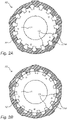
- Figures 2A and 2B show an alternative embodiment of a distribution plate 10 with two plate parts 11, 12 which are rotatable relative to each other.
- the part openings 13, 14 in the respective plate parts 11, 12 adjoin each other, and in figure 2B these part openings 13, 14 are moved apart such that they do not adjoin each other.
- by the relative movement not only is the scope of the passage openings changed but also the number of passage openings is changed.
- FIG 3 shows a perspective view of a distribution device 100 according to the present invention.
- the distribution device 100 comprises a cylindrical distribution chamber 101, on a first end side of which a supply 102 is connected for fluid substances such as for example fertilizer. This side also comprises several outlets 103 for the discharge of fluid substances via pipes (not shown) to be connected to the outlets 103.
- the distribution device 100 On a second end side of the distribution chamber 101, the distribution device 100 is provided with a drive 104 which is configured, by means of a drive shaft (not shown here), for driving a rotor 120 situated in the distribution chamber 101 (see figure 4 ).
- the second end side of the distribution chamber 101 is also provided with several outlets 103 and a gas inlet 107, which gas inlet 107 may be in contact with a gas supply (also not shown here).
- the distribution device 100 is furthermore provided with a foot 108 for fixing to an external structure such as a spreader arm (see figure 5 ).
- the foot 108 may serve as a settling reservoir for foreign parts such as stones and metal objects which may contaminate the fluid substance and cannot be chopped. These foreign parts may be periodically removed via an opening on the underside of the foot 108.
- two movable bars 109 are visible which are displaceable in slots 110 arranged in the housing 101. By displacement in the slots 110, the bars 109 can change the state of the adjustable cutting plates present in the distribution device, which are not shown here but for example correspond to the cutting plates shown in figures 1 , 2A and 2B .
- the bars 109 By moving the bars 109, the size of the openings in the cutting plates of the distribution device 100 can be adjusted.
- the bars 109 shown here can be moved manually, but it is also possible to provide a drive, for example in the form of a pneumatic or hydraulic cylinder or an electric motor, in order to mechanise and in some cases automate the operation of the bars 109.
- Figure 4 shows a cross-section through the distribution device 100 shown in figure 3 .
- a rotor 120 which is driven by the drive 104, and on the outside of which are several hollow tubular holders 121.
- the holders 121 are each configured for rotatably receiving one or more conical cutter blades 123 which are connected to hollow shanks 122.
- compression springs 124 are placed in the holders, for pressing the cutter blades 123 against a distribution plate 126 (also known as a cutting plate or perforated plate) arranged on a side wall 125 of the distribution chamber 101.
- the distribution plate 126 and side wall 125 of the distribution chamber 101 are provided with holes 127 which are arranged in a circle close to the circumference and to which outlets 128 are connected.
- the size (surface area) of the holes 127 can be adjusted because the size of the holes is determined by two plate parts 129, 130 which can be rotated relative to each other over a limited angular distance (only the segments of the plate part 129 shown as darker are visible, because in this figure the majority of the plate part 129 is hidden by the plate part 130).
- the mutual twist (rotation) of the plate parts 129, 130 allows the darker segments to be covered to a greater or lesser extent by the openings in the plate part 130.
- the size of the holes 127 is fully adjustable.
- the working of the distribution device 100 is as follows. Fluid substance enters the distribution chamber 101 via a supply (not shown here, but marked 102 in figure 3 ), after which it flows via a deflector element 131 of the rotor 120 from two sides in the direction of the outlets 128.
- the deflector element 131 may be configured as a removable plate in order to be able to eliminate any contamination or clogging (for example by rinsing with water).
- the cutter blades 123 chop any solid parts present in the fluid substance, and on rotation of the rotor 120 alternately cover the holes 127.
- the cutter blades 123 are also provided with an opening for supplying the outlet 128 with air or another gas.
- This gas is supplied in the direction of the rotor 120 via a gas inlet 132, at least partly through the drive shaft, after which the gas flows in the direction of tubular holders 121 via a side of the deflector element 131 facing the drive shaft. Via holes arranged in the tubular holders 121, the gas passes along the coils of the compression spring 124 through the hollow shanks 122 of the cutter blades 123 to emerge below the cutter blades 123.
- the distribution device 100 is mounted on an external structure of the fertilizer device. Also, the foot 108 may serve as a settling reservoir for foreign parts which cannot be chopped.
- FIG. 5 shows a diagrammatic view of a fertilizer device 150 (here in the form of a manure tanker) provided with a tank 151 and a substructure 152 with wheels 153.
- a metering device 154 is provided on the back of the substructure 152.
- the metering device 154 comprises a frame 155 which is attached to the substructure 152.
- the frame 155 is connected via horizontal frame rotation shafts 156 to a central metering arm segment 157.
- the central metering arm segment 157 is in the folded transport state in the figure.
- the central metering arm segment 157 may be folded down into a working position by means of cylinders 158.
- the central metering arm segment 157 is provided with fertilizer outlet elements 159 protruding obliquely upward.
- a second metering arm segment 160 (on the right in this figure) is pivotably connected to the central metering arm segment 157 and also carries protruding outlet elements 159, wherein the segment rotation axis (pivot axis between the central metering arm segment 157 and the second metering arm segment 160) is shown by a dotted line 161.
- a second metering arm segment 162 on the left is also pivotably attached to the central metering arm segment 157; in this figure description however, no further attention is paid to the second metering arm segment 162 on the left since it corresponds mirror-symmetrically to the second metering arm segment 160 on the right.
- the second metering arm segment 160 is provided with protruding outlet elements 159 that are connected by hoses (not shown in this figure for the sake of clarity) to the outlets 103 (in figure 3 , and marked 128 in figure 4 ), and connected to a fertilizer distribution device 100 which is incorporated in the second metering arm segment 160.
- hoses not shown in this figure for the sake of clarity
- the output of fluid fertilizer from the outlet elements 159 can thus be influenced.
Landscapes
- Life Sciences & Earth Sciences (AREA)
- Engineering & Computer Science (AREA)
- Water Supply & Treatment (AREA)
- Soil Sciences (AREA)
- Environmental Sciences (AREA)
- Fertilizing (AREA)
Claims (18)
- Verteilplatte (1, 10, 126) zur Verwendung in einer Verteileinrichtung (100) für flüssige Substanzen, wie z. B. Dünger, umfassend eine ebene Platte (1, 10, 126), die mit einer ebenen Versorgungsseite (5) versehen ist, in der mehrere Durchtrittsöffnungen (4, 127) für flüssige Substanzen vorgesehen sind, wobei die ebene Platte (1, 10, 126) mindestens zwei relativ zueinander bewegbare Plattenteile (2, 3; 11, 12; 129, 130) umfasst,
wobei die Größe mindestens einiger der Durchtrittsöffnungen (4, 127) durch die Relativbewegung der Plattenteile (2, 3; 11, 12; 129, 130) verändert werden kann, dadurch gekennzeichnet, dass die flache Versorgungsseite (5) der Verteilplatte (1, 10, 126) durch die mindestens zwei Plattenteile (2, 3; 11, 12; 129, 130) definiert ist. - Verteilplatte (1, 10, 126) gemäß Anspruch 1, dadurch gekennzeichnet, dass die Oberseiten einer Durchtrittsöffnung (4, 127) in der Verteilplatte (1, 10, 126) durch mindestens zwei relativ zueinander bewegbare Plattenteile (2, 3; 11, 12; 129, 130) gebildet sind.
- Verteilplatte (1, 10, 126) gemäß Anspruch 1 oder 2, dadurch gekennzeichnet, dass die Plattenteile (2, 3; 11, 12; 129, 130) relativ zueinander drehbar sind.
- Verteilplatte (1, 10, 126) gemäß einem der vorhergehenden Ansprüche, dadurch gekennzeichnet, dass die Plattenteile (2, 3; 11, 12; 129, 130) relativ zueinander verschiebbar sind.
- Verteilplatte (1, 10, 26) gemäß einem der vorhergehenden Ansprüche, dadurch gekennzeichnet, dass mindestens einige der Seiten der Durchtrittsöffnungen (4, 127) mit einer scharfen Kante, beispielsweise einer Kante mit einem Winkel von 80 - 100°, versehen sind.
- Verteilplatte (1, 10, 126) gemäß einem der vorhergehenden Ansprüche, dadurch gekennzeichnet, dass die Durchtrittsöffnungen (4, 127) zur flachen Versorgungsseite (5) hin selbstreinigend sind.
- Verteilplatte (1, 10, 126) gemäß einem der vorhergehenden Ansprüche, dadurch gekennzeichnet, dass die Verteilplatte (1, 10, 126) im Wesentlichen kreisförmig ist.
- Verteilplatte (1, 10, 126) gemäß Anspruch 7, dadurch gekennzeichnet, dass die Durchtrittsöffnungen (4, 127) im Wesentlichen koaxial in der Verteilplatte (1, 10, 126) angeordnet sind.
- Verteilplatte (1, 10, 126) gemäß einem der vorhergehenden Ansprüche, dadurch gekennzeichnet, dass die Durchtrittsöffnungen (4, 127) zueinander unterschiedliche Größen aufweisen.
- Verteilplatte (1, 10, 126) gemäß einem der vorhergehenden Ansprüche, dadurch gekennzeichnet, dass mindestens einige der Durchtrittsöffnungen (4, 127) durch die Relativbewegung der Plattenteile (2, 3; 11, 12; 129, 130) vollständig geschlossen werden können.
- Verteileinrichtung (100) für flüssige Substanzen, wie z. B. Düngemittel, umfassend:- eine Verteilkammer (101), die mit mindestens einem Zulauf (102) und mehreren Auslässen (103, 128) für flüssige Substanzen versehen ist;- eine verstellbare Verteilplatte (1, 10, 126) gemäß einem der vorhergehenden Ansprüche, die an die einzelnen Auslässe (103, 128) anschließt;- einen Rotor (120), der sich in der Verteilkammer (101) befindet und mit mindestens einem Schneidmesser (123) versehen ist, das entlang der Öffnungen (4, 127) in der Verteilplatte (1, 10, 126) bewegt werden kann, wobei das Schneidmesser (123) dazu ausgelegt ist, die Öffnungen (4, 127) abwechselnd abzudecken;- einen Antrieb (104) zum Antreiben des Rotors (120) mittels einer Antriebswelle; und- eine Gaszufuhr (107, 132), die mit der dem Auslass (103, 128) zugewandten Seite des Schneidmessers (123) verbunden ist.
- Verteileinrichtung (100) gemäß Anspruch 11, dadurch gekennzeichnet, dass die Einrichtung (100) mit einem Antrieb zur Relativbewegung der Plattenteile (2, 3; 11, 12; 129, 130) der verstellbaren Verteilplatte (1, 10, 126) versehen ist.
- Verteileinrichtung (100) gemäß Anspruch 12, dadurch gekennzeichnet, dass die Verteileinrichtung (100) mit mindestens einem Sensor versehen ist, der mit dem Antrieb der Plattenteile (2, 3; 11, 12; 129, 130) der verstellbaren Verteilplatte (1, 10, 126) gekoppelt ist.
- Düngeeinrichtung (150) zum Verteilen von flüssigen Substanzen, wie z. B. Dünger, über den Boden, die mit zwei Streuerarmen (160, 161) versehen ist, wobei die Streuerarme (160, 161) jeweils mit einer Anzahl von Verteilöffnungen (159) versehen sind, und wobei jeder der Streuerarme (160, 161) mit mindestens einer Verteileinrichtung (100) gemäß einem der Ansprüche 11 - 13 zum Verteilen von flüssiger Substanz über die Verteilöffnungen (159) von einer zentralen Düngemittelversorgung (151) mittels Rohren versehen ist,
wobei die Größe der Durchtrittsöffnungen (4, 127) der mindestens einen Verteilplatte (1, 10, 126) durch die Relativbewegung der Plattenteile (2, 3; 11, 12; 129, 130) der Verteilplatte (1, 10, 126) eingestellt werden kann. - Düngeeinrichtung (100) gemäß Anspruch 14, dadurch gekennzeichnet, dass die Einrichtung (100) mit einem Antrieb versehen ist, der mit mindestens einem der Plattenteile (2, 3; 11, 12; 129, 130) zur Relativbewegung der Plattenteile (2, 3; 11, 12; 129, 130) verbunden ist.
- Düngeeinrichtung (100) gemäß Anspruch 15, dadurch gekennzeichnet, dass der Antrieb mindestens eines der Plattenteile (2, 3; 11, 12; 129, 130) mit mindestens einem Sensor zur automatischen Erfassung physikalischer Größen gekoppelt ist.
- Düngeeinrichtung (100) gemäß Anspruch 15 oder 16, dadurch gekennzeichnet, dass der Antrieb mindestens eines der Plattenteile (2, 3; 11, 12; 129, 130) mit mindestens einem Sensor zur automatischen Standortbestimmung gekoppelt ist.
- Verfahren zum Einstellen des Durchsatzes einer Verteileinrichtung (100) für flüssige Substanzen gemäß einem der Ansprüche 11 - 13, wobei die Größe der Durchtrittsöffnungen (4, 127) der mindestens einen Verteilplatte (1, 10, 126) durch Relativbewegung der Plattenteile (2, 3; 11, 12; 129, 130) der Verteilplatte (1, 10, 126) eingestellt wird.
Applications Claiming Priority (1)
| Application Number | Priority Date | Filing Date | Title |
|---|---|---|---|
| NL2023238 | 2019-05-29 |
Publications (2)
| Publication Number | Publication Date |
|---|---|
| EP3744163A1 EP3744163A1 (de) | 2020-12-02 |
| EP3744163B1 true EP3744163B1 (de) | 2022-03-30 |
Family
ID=71579500
Family Applications (1)
| Application Number | Title | Priority Date | Filing Date |
|---|---|---|---|
| EP20177513.7A Active EP3744163B1 (de) | 2019-05-29 | 2020-05-29 | Düngeeinrichtung mit verteileinrichtung und -platte für flüssige substanzen, verfahren zum einstellen des durchsatzes |
Country Status (2)
| Country | Link |
|---|---|
| EP (1) | EP3744163B1 (de) |
| DK (1) | DK3744163T3 (de) |
Cited By (1)
| Publication number | Priority date | Publication date | Assignee | Title |
|---|---|---|---|---|
| TWI826300B (zh) * | 2023-04-07 | 2023-12-11 | 國立高雄科技大學 | 環保肥料膠囊 |
Families Citing this family (2)
| Publication number | Priority date | Publication date | Assignee | Title |
|---|---|---|---|---|
| DE102019215135A1 (de) * | 2019-10-01 | 2021-04-01 | Röhren- Und Pumpenwerk Bauer Ges.M.B.H. | Verteilvorrichtung für eine Trübe |
| DE202021102511U1 (de) * | 2021-05-07 | 2022-08-11 | Vogelsang Gmbh & Co. Kg | Verteilervorrichtung mit verstellbarem Durchtrittsquerschnitt |
Family Cites Families (4)
| Publication number | Priority date | Publication date | Assignee | Title |
|---|---|---|---|---|
| EP0772965A1 (de) * | 1995-11-09 | 1997-05-14 | Josef Fliegl | Gülleverteiler |
| DE20308082U1 (de) * | 2003-05-23 | 2004-09-30 | Hugo Vogelsang Maschinenbau Gmbh | Gerät zum Verteilen von Flüssigkeiten mit unterschiedlichen Viskositäten |
| DE102015121039A1 (de) | 2015-12-03 | 2017-06-08 | Bomech B.V. | Verteilvorrichtung, Düngevorrichtung und Verfahren zum Verteilen von flüssigen Substanzen |
| DE202018003796U1 (de) * | 2018-08-16 | 2018-09-07 | Stapel Gmbh | Verteilvorrichtung für eine mit Feststoffen befrachtete Flüssigkeit |
-
2020
- 2020-05-29 EP EP20177513.7A patent/EP3744163B1/de active Active
- 2020-05-29 DK DK20177513.7T patent/DK3744163T3/da active
Cited By (1)
| Publication number | Priority date | Publication date | Assignee | Title |
|---|---|---|---|---|
| TWI826300B (zh) * | 2023-04-07 | 2023-12-11 | 國立高雄科技大學 | 環保肥料膠囊 |
Also Published As
| Publication number | Publication date |
|---|---|
| EP3744163A1 (de) | 2020-12-02 |
| DK3744163T3 (da) | 2022-06-13 |
Similar Documents
| Publication | Publication Date | Title |
|---|---|---|
| EP3744163B1 (de) | Düngeeinrichtung mit verteileinrichtung und -platte für flüssige substanzen, verfahren zum einstellen des durchsatzes | |
| EP3175696B1 (de) | Verteilungsvorrichtung, gülleausbringvorrichtung und verfahren zur verteilung von flüssigen substanzen | |
| US4926622A (en) | Combined rotary cutter and herbicide applicator and method | |
| RU2211555C2 (ru) | Дозировочная система высевающего устройства | |
| EP0074155A1 (de) | Pulverstreuvorrichtung | |
| AU2017203665A1 (en) | Modular metering apparatus for an air seeder | |
| EP3051938B1 (de) | Landwirtschaftliche verteilmaschine mit einem dosiersystem | |
| NZ208359A (en) | Fertiliser spreader: coverage reducible by adjustment | |
| US7624692B2 (en) | Sand dispenser for a scarifier | |
| EP0520784B1 (de) | Verbesserungen an Vorrichtungen zum Einbringen von Gülle oder weiteren Flüssigkeiten in den Boden | |
| EP3840562A1 (de) | Dosiereinheit für pulver- oder partikelförmiges verteilgut und verteilmaschine mit einer solchen dosiereinheit | |
| EP2183952B1 (de) | Säherz und Einzelkornsämaschine | |
| DE102007038510B4 (de) | Vorrichtung zum Dosieren und Verteilen von landwirtschaftlichen und kommunalen Schüttgütern | |
| US6293438B1 (en) | Methods and apparatus for metering material | |
| GB2251166A (en) | Slurry spreaders | |
| CA1224824A (en) | Apparatus for spreading granular material | |
| DE3935104A1 (de) | Schleuderduengerstreuer | |
| EP3359742B1 (de) | Winterdienst-streugerät | |
| US20120032003A1 (en) | Distribution system for liquid manure spreader | |
| DE10248613B4 (de) | Streugerät | |
| CN210434004U (zh) | 一种新型降膜蒸发器物料布料装置 | |
| SI25841A (sl) | Izboljšan sekljalnik gnojevke za razdeljevalnik gnojevke in razdeljevalnik z omenjenim sekljalnikom | |
| DE29715481U1 (de) | Gerät zum Verteilen von Gülle und Klärschlamm | |
| DE4021266A1 (de) | Vorrichtung zum einbringen von fluessigduenger, insbesondere mischduenger, in den boden | |
| EP4321008A1 (de) | Verteilungsvorrichtung für flüssige substanzen |
Legal Events
| Date | Code | Title | Description |
|---|---|---|---|
| PUAI | Public reference made under article 153(3) epc to a published international application that has entered the european phase |
Free format text: ORIGINAL CODE: 0009012 |
|
| STAA | Information on the status of an ep patent application or granted ep patent |
Free format text: STATUS: THE APPLICATION HAS BEEN PUBLISHED |
|
| AK | Designated contracting states |
Kind code of ref document: A1 Designated state(s): AL AT BE BG CH CY CZ DE DK EE ES FI FR GB GR HR HU IE IS IT LI LT LU LV MC MK MT NL NO PL PT RO RS SE SI SK SM TR |
|
| AX | Request for extension of the european patent |
Extension state: BA ME |
|
| STAA | Information on the status of an ep patent application or granted ep patent |
Free format text: STATUS: REQUEST FOR EXAMINATION WAS MADE |
|
| 17P | Request for examination filed |
Effective date: 20210602 |
|
| RBV | Designated contracting states (corrected) |
Designated state(s): AL AT BE BG CH CY CZ DE DK EE ES FI FR GB GR HR HU IE IS IT LI LT LU LV MC MK MT NL NO PL PT RO RS SE SI SK SM TR |
|
| GRAP | Despatch of communication of intention to grant a patent |
Free format text: ORIGINAL CODE: EPIDOSNIGR1 |
|
| STAA | Information on the status of an ep patent application or granted ep patent |
Free format text: STATUS: GRANT OF PATENT IS INTENDED |
|
| RIC1 | Information provided on ipc code assigned before grant |
Ipc: A01C 23/00 20060101AFI20210930BHEP |
|
| INTG | Intention to grant announced |
Effective date: 20211015 |
|
| GRAS | Grant fee paid |
Free format text: ORIGINAL CODE: EPIDOSNIGR3 |
|
| GRAA | (expected) grant |
Free format text: ORIGINAL CODE: 0009210 |
|
| STAA | Information on the status of an ep patent application or granted ep patent |
Free format text: STATUS: THE PATENT HAS BEEN GRANTED |
|
| AK | Designated contracting states |
Kind code of ref document: B1 Designated state(s): AL AT BE BG CH CY CZ DE DK EE ES FI FR GB GR HR HU IE IS IT LI LT LU LV MC MK MT NL NO PL PT RO RS SE SI SK SM TR |
|
| REG | Reference to a national code |
Ref country code: GB Ref legal event code: FG4D |
|
| REG | Reference to a national code |
Ref country code: CH Ref legal event code: EP |
|
| REG | Reference to a national code |
Ref country code: AT Ref legal event code: REF Ref document number: 1478355 Country of ref document: AT Kind code of ref document: T Effective date: 20220415 |
|
| REG | Reference to a national code |
Ref country code: DE Ref legal event code: R096 Ref document number: 602020002406 Country of ref document: DE |
|
| REG | Reference to a national code |
Ref country code: IE Ref legal event code: FG4D |
|
| REG | Reference to a national code |
Ref country code: NL Ref legal event code: FP |
|
| REG | Reference to a national code |
Ref country code: DK Ref legal event code: T3 Effective date: 20220608 |
|
| REG | Reference to a national code |
Ref country code: LT Ref legal event code: MG9D |
|
| PG25 | Lapsed in a contracting state [announced via postgrant information from national office to epo] |
Ref country code: SE Free format text: LAPSE BECAUSE OF FAILURE TO SUBMIT A TRANSLATION OF THE DESCRIPTION OR TO PAY THE FEE WITHIN THE PRESCRIBED TIME-LIMIT Effective date: 20220330 Ref country code: RS Free format text: LAPSE BECAUSE OF FAILURE TO SUBMIT A TRANSLATION OF THE DESCRIPTION OR TO PAY THE FEE WITHIN THE PRESCRIBED TIME-LIMIT Effective date: 20220330 Ref country code: NO Free format text: LAPSE BECAUSE OF FAILURE TO SUBMIT A TRANSLATION OF THE DESCRIPTION OR TO PAY THE FEE WITHIN THE PRESCRIBED TIME-LIMIT Effective date: 20220630 Ref country code: LT Free format text: LAPSE BECAUSE OF FAILURE TO SUBMIT A TRANSLATION OF THE DESCRIPTION OR TO PAY THE FEE WITHIN THE PRESCRIBED TIME-LIMIT Effective date: 20220330 Ref country code: HR Free format text: LAPSE BECAUSE OF FAILURE TO SUBMIT A TRANSLATION OF THE DESCRIPTION OR TO PAY THE FEE WITHIN THE PRESCRIBED TIME-LIMIT Effective date: 20220330 Ref country code: BG Free format text: LAPSE BECAUSE OF FAILURE TO SUBMIT A TRANSLATION OF THE DESCRIPTION OR TO PAY THE FEE WITHIN THE PRESCRIBED TIME-LIMIT Effective date: 20220630 |
|
| REG | Reference to a national code |
Ref country code: AT Ref legal event code: MK05 Ref document number: 1478355 Country of ref document: AT Kind code of ref document: T Effective date: 20220330 |
|
| PG25 | Lapsed in a contracting state [announced via postgrant information from national office to epo] |
Ref country code: LV Free format text: LAPSE BECAUSE OF FAILURE TO SUBMIT A TRANSLATION OF THE DESCRIPTION OR TO PAY THE FEE WITHIN THE PRESCRIBED TIME-LIMIT Effective date: 20220330 Ref country code: GR Free format text: LAPSE BECAUSE OF FAILURE TO SUBMIT A TRANSLATION OF THE DESCRIPTION OR TO PAY THE FEE WITHIN THE PRESCRIBED TIME-LIMIT Effective date: 20220701 Ref country code: FI Free format text: LAPSE BECAUSE OF FAILURE TO SUBMIT A TRANSLATION OF THE DESCRIPTION OR TO PAY THE FEE WITHIN THE PRESCRIBED TIME-LIMIT Effective date: 20220330 |
|
| PG25 | Lapsed in a contracting state [announced via postgrant information from national office to epo] |
Ref country code: SM Free format text: LAPSE BECAUSE OF FAILURE TO SUBMIT A TRANSLATION OF THE DESCRIPTION OR TO PAY THE FEE WITHIN THE PRESCRIBED TIME-LIMIT Effective date: 20220330 Ref country code: SK Free format text: LAPSE BECAUSE OF FAILURE TO SUBMIT A TRANSLATION OF THE DESCRIPTION OR TO PAY THE FEE WITHIN THE PRESCRIBED TIME-LIMIT Effective date: 20220330 Ref country code: RO Free format text: LAPSE BECAUSE OF FAILURE TO SUBMIT A TRANSLATION OF THE DESCRIPTION OR TO PAY THE FEE WITHIN THE PRESCRIBED TIME-LIMIT Effective date: 20220330 Ref country code: PT Free format text: LAPSE BECAUSE OF FAILURE TO SUBMIT A TRANSLATION OF THE DESCRIPTION OR TO PAY THE FEE WITHIN THE PRESCRIBED TIME-LIMIT Effective date: 20220801 Ref country code: ES Free format text: LAPSE BECAUSE OF FAILURE TO SUBMIT A TRANSLATION OF THE DESCRIPTION OR TO PAY THE FEE WITHIN THE PRESCRIBED TIME-LIMIT Effective date: 20220330 Ref country code: EE Free format text: LAPSE BECAUSE OF FAILURE TO SUBMIT A TRANSLATION OF THE DESCRIPTION OR TO PAY THE FEE WITHIN THE PRESCRIBED TIME-LIMIT Effective date: 20220330 Ref country code: CZ Free format text: LAPSE BECAUSE OF FAILURE TO SUBMIT A TRANSLATION OF THE DESCRIPTION OR TO PAY THE FEE WITHIN THE PRESCRIBED TIME-LIMIT Effective date: 20220330 Ref country code: AT Free format text: LAPSE BECAUSE OF FAILURE TO SUBMIT A TRANSLATION OF THE DESCRIPTION OR TO PAY THE FEE WITHIN THE PRESCRIBED TIME-LIMIT Effective date: 20220330 |
|
| PG25 | Lapsed in a contracting state [announced via postgrant information from national office to epo] |
Ref country code: PL Free format text: LAPSE BECAUSE OF FAILURE TO SUBMIT A TRANSLATION OF THE DESCRIPTION OR TO PAY THE FEE WITHIN THE PRESCRIBED TIME-LIMIT Effective date: 20220330 Ref country code: IS Free format text: LAPSE BECAUSE OF FAILURE TO SUBMIT A TRANSLATION OF THE DESCRIPTION OR TO PAY THE FEE WITHIN THE PRESCRIBED TIME-LIMIT Effective date: 20220730 Ref country code: AL Free format text: LAPSE BECAUSE OF FAILURE TO SUBMIT A TRANSLATION OF THE DESCRIPTION OR TO PAY THE FEE WITHIN THE PRESCRIBED TIME-LIMIT Effective date: 20220330 |
|
| REG | Reference to a national code |
Ref country code: DE Ref legal event code: R097 Ref document number: 602020002406 Country of ref document: DE |
|
| PG25 | Lapsed in a contracting state [announced via postgrant information from national office to epo] |
Ref country code: MC Free format text: LAPSE BECAUSE OF FAILURE TO SUBMIT A TRANSLATION OF THE DESCRIPTION OR TO PAY THE FEE WITHIN THE PRESCRIBED TIME-LIMIT Effective date: 20220330 Ref country code: LU Free format text: LAPSE BECAUSE OF NON-PAYMENT OF DUE FEES Effective date: 20220529 |
|
| PLBE | No opposition filed within time limit |
Free format text: ORIGINAL CODE: 0009261 |
|
| STAA | Information on the status of an ep patent application or granted ep patent |
Free format text: STATUS: NO OPPOSITION FILED WITHIN TIME LIMIT |
|
| 26N | No opposition filed |
Effective date: 20230103 |
|
| PG25 | Lapsed in a contracting state [announced via postgrant information from national office to epo] |
Ref country code: SI Free format text: LAPSE BECAUSE OF FAILURE TO SUBMIT A TRANSLATION OF THE DESCRIPTION OR TO PAY THE FEE WITHIN THE PRESCRIBED TIME-LIMIT Effective date: 20220330 |
|
| P01 | Opt-out of the competence of the unified patent court (upc) registered |
Effective date: 20230515 |
|
| PG25 | Lapsed in a contracting state [announced via postgrant information from national office to epo] |
Ref country code: IT Free format text: LAPSE BECAUSE OF FAILURE TO SUBMIT A TRANSLATION OF THE DESCRIPTION OR TO PAY THE FEE WITHIN THE PRESCRIBED TIME-LIMIT Effective date: 20220330 |
|
| REG | Reference to a national code |
Ref country code: CH Ref legal event code: PL |
|
| PG25 | Lapsed in a contracting state [announced via postgrant information from national office to epo] |
Ref country code: LI Free format text: LAPSE BECAUSE OF NON-PAYMENT OF DUE FEES Effective date: 20230531 Ref country code: CH Free format text: LAPSE BECAUSE OF NON-PAYMENT OF DUE FEES Effective date: 20230531 |
|
| PG25 | Lapsed in a contracting state [announced via postgrant information from national office to epo] |
Ref country code: MK Free format text: LAPSE BECAUSE OF FAILURE TO SUBMIT A TRANSLATION OF THE DESCRIPTION OR TO PAY THE FEE WITHIN THE PRESCRIBED TIME-LIMIT Effective date: 20220330 Ref country code: CY Free format text: LAPSE BECAUSE OF FAILURE TO SUBMIT A TRANSLATION OF THE DESCRIPTION OR TO PAY THE FEE WITHIN THE PRESCRIBED TIME-LIMIT Effective date: 20220330 |
|
| PG25 | Lapsed in a contracting state [announced via postgrant information from national office to epo] |
Ref country code: HU Free format text: LAPSE BECAUSE OF FAILURE TO SUBMIT A TRANSLATION OF THE DESCRIPTION OR TO PAY THE FEE WITHIN THE PRESCRIBED TIME-LIMIT; INVALID AB INITIO Effective date: 20200529 |
|
| PGFP | Annual fee paid to national office [announced via postgrant information from national office to epo] |
Ref country code: NL Payment date: 20240526 Year of fee payment: 5 |
|
| PG25 | Lapsed in a contracting state [announced via postgrant information from national office to epo] |
Ref country code: TR Free format text: LAPSE BECAUSE OF FAILURE TO SUBMIT A TRANSLATION OF THE DESCRIPTION OR TO PAY THE FEE WITHIN THE PRESCRIBED TIME-LIMIT Effective date: 20220330 |
|
| PGFP | Annual fee paid to national office [announced via postgrant information from national office to epo] |
Ref country code: IE Payment date: 20240527 Year of fee payment: 5 |
|
| PGFP | Annual fee paid to national office [announced via postgrant information from national office to epo] |
Ref country code: DE Payment date: 20240530 Year of fee payment: 5 |
|
| PGFP | Annual fee paid to national office [announced via postgrant information from national office to epo] |
Ref country code: DK Payment date: 20240527 Year of fee payment: 5 |
|
| PGFP | Annual fee paid to national office [announced via postgrant information from national office to epo] |
Ref country code: FR Payment date: 20240527 Year of fee payment: 5 |
|
| PGFP | Annual fee paid to national office [announced via postgrant information from national office to epo] |
Ref country code: BE Payment date: 20240527 Year of fee payment: 5 |