EP3744082B1 - Folded camera with actuator for moving optics - Google Patents
Folded camera with actuator for moving optics Download PDFInfo
- Publication number
- EP3744082B1 EP3744082B1 EP19706326.6A EP19706326A EP3744082B1 EP 3744082 B1 EP3744082 B1 EP 3744082B1 EP 19706326 A EP19706326 A EP 19706326A EP 3744082 B1 EP3744082 B1 EP 3744082B1
- Authority
- EP
- European Patent Office
- Prior art keywords
- ois
- prism
- lens group
- camera
- magnet
- Prior art date
- Legal status (The legal status is an assumption and is not a legal conclusion. Google has not performed a legal analysis and makes no representation as to the accuracy of the status listed.)
- Active
Links
Images















Classifications
-
- G—PHYSICS
- G02—OPTICS
- G02B—OPTICAL ELEMENTS, SYSTEMS OR APPARATUS
- G02B13/00—Optical objectives specially designed for the purposes specified below
- G02B13/001—Miniaturised objectives for electronic devices, e.g. portable telephones, webcams, PDAs, small digital cameras
- G02B13/0055—Miniaturised objectives for electronic devices, e.g. portable telephones, webcams, PDAs, small digital cameras employing a special optical element
- G02B13/0065—Miniaturised objectives for electronic devices, e.g. portable telephones, webcams, PDAs, small digital cameras employing a special optical element having a beam-folding prism or mirror
-
- G—PHYSICS
- G02—OPTICS
- G02B—OPTICAL ELEMENTS, SYSTEMS OR APPARATUS
- G02B27/00—Optical systems or apparatus not provided for by any of the groups G02B1/00 - G02B26/00, G02B30/00
- G02B27/09—Beam shaping, e.g. changing the cross-sectional area, not otherwise provided for
- G02B27/0938—Using specific optical elements
- G02B27/095—Refractive optical elements
- G02B27/0972—Prisms
-
- G—PHYSICS
- G02—OPTICS
- G02B—OPTICAL ELEMENTS, SYSTEMS OR APPARATUS
- G02B27/00—Optical systems or apparatus not provided for by any of the groups G02B1/00 - G02B26/00, G02B30/00
- G02B27/09—Beam shaping, e.g. changing the cross-sectional area, not otherwise provided for
- G02B27/0938—Using specific optical elements
- G02B27/0977—Reflective elements
-
- G—PHYSICS
- G02—OPTICS
- G02B—OPTICAL ELEMENTS, SYSTEMS OR APPARATUS
- G02B27/00—Optical systems or apparatus not provided for by any of the groups G02B1/00 - G02B26/00, G02B30/00
- G02B27/64—Imaging systems using optical elements for stabilisation of the lateral and angular position of the image
- G02B27/646—Imaging systems using optical elements for stabilisation of the lateral and angular position of the image compensating for small deviations, e.g. due to vibration or shake
-
- G—PHYSICS
- G02—OPTICS
- G02B—OPTICAL ELEMENTS, SYSTEMS OR APPARATUS
- G02B7/00—Mountings, adjusting means, or light-tight connections, for optical elements
- G02B7/02—Mountings, adjusting means, or light-tight connections, for optical elements for lenses
- G02B7/04—Mountings, adjusting means, or light-tight connections, for optical elements for lenses with mechanism for focusing or varying magnification
- G02B7/08—Mountings, adjusting means, or light-tight connections, for optical elements for lenses with mechanism for focusing or varying magnification adapted to co-operate with a remote control mechanism
-
- G—PHYSICS
- G02—OPTICS
- G02B—OPTICAL ELEMENTS, SYSTEMS OR APPARATUS
- G02B7/00—Mountings, adjusting means, or light-tight connections, for optical elements
- G02B7/02—Mountings, adjusting means, or light-tight connections, for optical elements for lenses
- G02B7/04—Mountings, adjusting means, or light-tight connections, for optical elements for lenses with mechanism for focusing or varying magnification
- G02B7/09—Mountings, adjusting means, or light-tight connections, for optical elements for lenses with mechanism for focusing or varying magnification adapted for automatic focusing or varying magnification
-
- G—PHYSICS
- G03—PHOTOGRAPHY; CINEMATOGRAPHY; ANALOGOUS TECHNIQUES USING WAVES OTHER THAN OPTICAL WAVES; ELECTROGRAPHY; HOLOGRAPHY
- G03B—APPARATUS OR ARRANGEMENTS FOR TAKING PHOTOGRAPHS OR FOR PROJECTING OR VIEWING THEM; APPARATUS OR ARRANGEMENTS EMPLOYING ANALOGOUS TECHNIQUES USING WAVES OTHER THAN OPTICAL WAVES; ACCESSORIES THEREFOR
- G03B13/00—Viewfinders; Focusing aids for cameras; Means for focusing for cameras; Autofocus systems for cameras
- G03B13/32—Means for focusing
- G03B13/34—Power focusing
- G03B13/36—Autofocus systems
-
- G—PHYSICS
- G03—PHOTOGRAPHY; CINEMATOGRAPHY; ANALOGOUS TECHNIQUES USING WAVES OTHER THAN OPTICAL WAVES; ELECTROGRAPHY; HOLOGRAPHY
- G03B—APPARATUS OR ARRANGEMENTS FOR TAKING PHOTOGRAPHS OR FOR PROJECTING OR VIEWING THEM; APPARATUS OR ARRANGEMENTS EMPLOYING ANALOGOUS TECHNIQUES USING WAVES OTHER THAN OPTICAL WAVES; ACCESSORIES THEREFOR
- G03B17/00—Details of cameras or camera bodies; Accessories therefor
- G03B17/02—Bodies
- G03B17/12—Bodies with means for supporting objectives, supplementary lenses, filters, masks, or turrets
-
- G—PHYSICS
- G03—PHOTOGRAPHY; CINEMATOGRAPHY; ANALOGOUS TECHNIQUES USING WAVES OTHER THAN OPTICAL WAVES; ELECTROGRAPHY; HOLOGRAPHY
- G03B—APPARATUS OR ARRANGEMENTS FOR TAKING PHOTOGRAPHS OR FOR PROJECTING OR VIEWING THEM; APPARATUS OR ARRANGEMENTS EMPLOYING ANALOGOUS TECHNIQUES USING WAVES OTHER THAN OPTICAL WAVES; ACCESSORIES THEREFOR
- G03B17/00—Details of cameras or camera bodies; Accessories therefor
- G03B17/02—Bodies
- G03B17/17—Bodies with reflectors arranged in beam forming the photographic image, e.g. for reducing dimensions of camera
-
- G—PHYSICS
- G03—PHOTOGRAPHY; CINEMATOGRAPHY; ANALOGOUS TECHNIQUES USING WAVES OTHER THAN OPTICAL WAVES; ELECTROGRAPHY; HOLOGRAPHY
- G03B—APPARATUS OR ARRANGEMENTS FOR TAKING PHOTOGRAPHS OR FOR PROJECTING OR VIEWING THEM; APPARATUS OR ARRANGEMENTS EMPLOYING ANALOGOUS TECHNIQUES USING WAVES OTHER THAN OPTICAL WAVES; ACCESSORIES THEREFOR
- G03B3/00—Focusing arrangements of general interest for cameras, projectors or printers
- G03B3/10—Power-operated focusing
-
- G—PHYSICS
- G03—PHOTOGRAPHY; CINEMATOGRAPHY; ANALOGOUS TECHNIQUES USING WAVES OTHER THAN OPTICAL WAVES; ELECTROGRAPHY; HOLOGRAPHY
- G03B—APPARATUS OR ARRANGEMENTS FOR TAKING PHOTOGRAPHS OR FOR PROJECTING OR VIEWING THEM; APPARATUS OR ARRANGEMENTS EMPLOYING ANALOGOUS TECHNIQUES USING WAVES OTHER THAN OPTICAL WAVES; ACCESSORIES THEREFOR
- G03B30/00—Camera modules comprising integrated lens units and imaging units, specially adapted for being embedded in other devices, e.g. mobile phones or vehicles
-
- G—PHYSICS
- G03—PHOTOGRAPHY; CINEMATOGRAPHY; ANALOGOUS TECHNIQUES USING WAVES OTHER THAN OPTICAL WAVES; ELECTROGRAPHY; HOLOGRAPHY
- G03B—APPARATUS OR ARRANGEMENTS FOR TAKING PHOTOGRAPHS OR FOR PROJECTING OR VIEWING THEM; APPARATUS OR ARRANGEMENTS EMPLOYING ANALOGOUS TECHNIQUES USING WAVES OTHER THAN OPTICAL WAVES; ACCESSORIES THEREFOR
- G03B5/00—Adjustment of optical system relative to image or object surface other than for focusing
-
- G—PHYSICS
- G06—COMPUTING OR CALCULATING; COUNTING
- G06F—ELECTRIC DIGITAL DATA PROCESSING
- G06F9/00—Arrangements for program control, e.g. control units
- G06F9/06—Arrangements for program control, e.g. control units using stored programs, i.e. using an internal store of processing equipment to receive or retain programs
- G06F9/30—Arrangements for executing machine instructions, e.g. instruction decode
- G06F9/30003—Arrangements for executing specific machine instructions
- G06F9/3004—Arrangements for executing specific machine instructions to perform operations on memory
-
- H—ELECTRICITY
- H02—GENERATION; CONVERSION OR DISTRIBUTION OF ELECTRIC POWER
- H02K—DYNAMO-ELECTRIC MACHINES
- H02K41/00—Propulsion systems in which a rigid body is moved along a path due to dynamo-electric interaction between the body and a magnetic field travelling along the path
- H02K41/02—Linear motors; Sectional motors
- H02K41/035—DC motors; Unipolar motors
- H02K41/0352—Unipolar motors
- H02K41/0354—Lorentz force motors, e.g. voice coil motors
- H02K41/0356—Lorentz force motors, e.g. voice coil motors moving along a straight path
-
- H—ELECTRICITY
- H04—ELECTRIC COMMUNICATION TECHNIQUE
- H04N—PICTORIAL COMMUNICATION, e.g. TELEVISION
- H04N23/00—Cameras or camera modules comprising electronic image sensors; Control thereof
- H04N23/50—Constructional details
- H04N23/54—Mounting of pick-up tubes, electronic image sensors, deviation or focusing coils
-
- H—ELECTRICITY
- H04—ELECTRIC COMMUNICATION TECHNIQUE
- H04N—PICTORIAL COMMUNICATION, e.g. TELEVISION
- H04N23/00—Cameras or camera modules comprising electronic image sensors; Control thereof
- H04N23/50—Constructional details
- H04N23/55—Optical parts specially adapted for electronic image sensors; Mounting thereof
-
- H—ELECTRICITY
- H04—ELECTRIC COMMUNICATION TECHNIQUE
- H04N—PICTORIAL COMMUNICATION, e.g. TELEVISION
- H04N23/00—Cameras or camera modules comprising electronic image sensors; Control thereof
- H04N23/57—Mechanical or electrical details of cameras or camera modules specially adapted for being embedded in other devices
-
- H—ELECTRICITY
- H04—ELECTRIC COMMUNICATION TECHNIQUE
- H04N—PICTORIAL COMMUNICATION, e.g. TELEVISION
- H04N23/00—Cameras or camera modules comprising electronic image sensors; Control thereof
- H04N23/60—Control of cameras or camera modules
- H04N23/68—Control of cameras or camera modules for stable pick-up of the scene, e.g. compensating for camera body vibrations
- H04N23/682—Vibration or motion blur correction
- H04N23/685—Vibration or motion blur correction performed by mechanical compensation
-
- G—PHYSICS
- G03—PHOTOGRAPHY; CINEMATOGRAPHY; ANALOGOUS TECHNIQUES USING WAVES OTHER THAN OPTICAL WAVES; ELECTROGRAPHY; HOLOGRAPHY
- G03B—APPARATUS OR ARRANGEMENTS FOR TAKING PHOTOGRAPHS OR FOR PROJECTING OR VIEWING THEM; APPARATUS OR ARRANGEMENTS EMPLOYING ANALOGOUS TECHNIQUES USING WAVES OTHER THAN OPTICAL WAVES; ACCESSORIES THEREFOR
- G03B2205/00—Adjustment of optical system relative to image or object surface other than for focusing
- G03B2205/0007—Movement of one or more optical elements for control of motion blur
-
- G—PHYSICS
- G03—PHOTOGRAPHY; CINEMATOGRAPHY; ANALOGOUS TECHNIQUES USING WAVES OTHER THAN OPTICAL WAVES; ELECTROGRAPHY; HOLOGRAPHY
- G03B—APPARATUS OR ARRANGEMENTS FOR TAKING PHOTOGRAPHS OR FOR PROJECTING OR VIEWING THEM; APPARATUS OR ARRANGEMENTS EMPLOYING ANALOGOUS TECHNIQUES USING WAVES OTHER THAN OPTICAL WAVES; ACCESSORIES THEREFOR
- G03B2205/00—Adjustment of optical system relative to image or object surface other than for focusing
- G03B2205/0007—Movement of one or more optical elements for control of motion blur
- G03B2205/0015—Movement of one or more optical elements for control of motion blur by displacing one or more optical elements normal to the optical axis
-
- G—PHYSICS
- G03—PHOTOGRAPHY; CINEMATOGRAPHY; ANALOGOUS TECHNIQUES USING WAVES OTHER THAN OPTICAL WAVES; ELECTROGRAPHY; HOLOGRAPHY
- G03B—APPARATUS OR ARRANGEMENTS FOR TAKING PHOTOGRAPHS OR FOR PROJECTING OR VIEWING THEM; APPARATUS OR ARRANGEMENTS EMPLOYING ANALOGOUS TECHNIQUES USING WAVES OTHER THAN OPTICAL WAVES; ACCESSORIES THEREFOR
- G03B2205/00—Adjustment of optical system relative to image or object surface other than for focusing
- G03B2205/0053—Driving means for the movement of one or more optical element
-
- G—PHYSICS
- G03—PHOTOGRAPHY; CINEMATOGRAPHY; ANALOGOUS TECHNIQUES USING WAVES OTHER THAN OPTICAL WAVES; ELECTROGRAPHY; HOLOGRAPHY
- G03B—APPARATUS OR ARRANGEMENTS FOR TAKING PHOTOGRAPHS OR FOR PROJECTING OR VIEWING THEM; APPARATUS OR ARRANGEMENTS EMPLOYING ANALOGOUS TECHNIQUES USING WAVES OTHER THAN OPTICAL WAVES; ACCESSORIES THEREFOR
- G03B2205/00—Adjustment of optical system relative to image or object surface other than for focusing
- G03B2205/0053—Driving means for the movement of one or more optical element
- G03B2205/0069—Driving means for the movement of one or more optical element using electromagnetic actuators, e.g. voice coils
Definitions
- This disclosure relates generally to architecture for a camera with folded optics and lens shifting capabilities.
- Some small form factor cameras may incorporate optical image stabilization (OIS) mechanisms that may sense and react to external excitation/disturbance by adjusting location of the optical lens on the X and/or Y axis in an attempt to compensate for unwanted motion of the lens.
- OIS optical image stabilization
- Some small form factor cameras may incorporate an autofocus (AF) mechanism whereby the object focal distance can be adjusted to focus an object plane in front of the camera at an image plane to be captured by the image sensor. In some such autofocus mechanisms, the optical lens is moved as a single rigid body along the optical axis of the camera to refocus the camera.
- WO 2017/037688 A1 describes a folded digital camera module comprising an optical path folding element (OPFE) for folding light from a first optical path with a first optical axis to a second optical path with a second optical axis perpendicular to the first optical axis, an image sensor, and a lens module carrying a lens with a symmetry axis parallel to the second optical axis.
- OPFE optical path folding element
- US 2012/314307 A1 describes a lens actuator that includes a carrier that is configured to retain a lens; a first AF coil that is disposed in the carrier while wound about an axis perpendicular to a lens retaining surface; first to fourth magnets that are disposed opposite the first AF coil in four directions parallel to the lens retaining surface; a first OIS coil that is disposed opposite the first magnet; and a second OIS coil that is disposed opposite the second magnet.
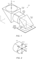
- the camera 100 includes a lens group 102, a first prism 104, a second prism 106, and an image sensor package 108.
- the lens group 102 includes one or more lens elements.
- the lens group 102 is located between the first prism 104 and the second prism 106, forming the folded optics arrangement.
- Light may follow an optical path 110 that is folded by the first prism 104 such that the light is directed towards the lens group 102, passes through the lens group 102, and is folded by the second prism 106 such that the light is directed towards the image sensor package 108.
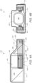
- light may enter an object side of the first prism 104 along the Z-axis.
- the first prism 104 may redirect the light to propagate along the X-axis (which may be parallel to an optical axis defined by the lens group 102) towards the lens group 102.
- the second prism 106 may redirect the light to propagate along the Z-axis (which may be orthogonal to a plane defined by the image sensor package 108), e.g., such that the light exits an image side of the second prism 106 towards the image sensor package 108.
- the first prism 104, the lens group 102, and/or the second prism 106 are positioned along a common axis (e.g., the X-axis, the optical axis defined by the lens group 102, etc.).
- the optical path 110 may be contained within a plane (e.g., the X-Z plane), and the image sensor package 108 may extend along a different plane (e.g., the X-Y plane).
- the object side of the first prism 104 may extend along the X-Y plane.
- the first prism 104 may include a pair of opposing lateral sides that each extend along the X-Z plane, a lens group facing side that extends along the Y-Z plane, and a reflecting surface side that is angled relative to one or more of the other sides of the first prism 104.
- the reflecting surface side of the first prism 104 may include a reflective surface that is angled so as to redirect light received from the object side of the first prism 104 towards the lens group 102 (via the lens group facing side of the first prism 104), as discussed above.
- the OIS-Y VCM actuator 320 may include one or more OIS-Y coils 330.
- the OIS-Y coils 330 may be attached to the fixed structure 316.
- each OIS-Y coil 330 may be located below a respective shared OIS magnet 328.
- the OIS-Y coils 330 may be electrically driven to magnetically interact with the shared OIS magnets 328 to produce Lorentz forces that move the shared OIS magnets 328, the magnet holder 314, and/or the lens group 302 along an axis (e.g., along the Y-axis) to provide OIS-Y movement (e.g., movement that shifts an image projected on the image sensor in one or more directions parallel to the Y-axis).
- the OIS-Y coils 330 may be oriented such that directions of current flow through the OIS-Y coils 330 define a respective plane that is substantially parallel to a surface of the fixed structure 316 (e.g., the surface on which the OIS-Y coils 330 are mounted).
- the camera 300 may include a substrate below the second prism 306.
- An image sensor may be coupled to the substrate.
- a filter e.g., an infrared filter
- the filter may be located above the image sensor such that light passes through the filter before reaching the image sensor.
- the substrate may be parallel to the fixed structure 316. Additionally, or alternatively, the fixed structure 316 may include the substrate and/or one or more other components.
- the camera 400 includes an actuator module 410 that provides for shifting the lens group 402 along multiple axes, e.g., to provide AF and/or OIS movement.
- the actuator module 410 may comprise a voice coil motor (VCM) actuator module that includes one or more VCM actuators.
- VCM voice coil motor
- the actuator module 410 may include one or more magnets and one or more coils. The magnets and coils may magnetically interact (e.g., when electrical current is provided to the coils) to produce Lorentz forces that move the lens group 402.
- the camera 400 includes a carrier arrangement that includes an inner carrier structure (e.g., the lens barrel 408 and/or a lens carrier) and an outer carrier structure (e.g., a magnet holder 412 and/or a magnet frame).
- One or more coils may be coupled to the inner carrier structure (e.g., to the lens barrel 408 and/or a lens carrier).
- one or more magnets may be coupled to the outer carrier structure (e.g., to the magnet holder 412).
- the magnet holder 412 may extend at least partially around the first prism 404, at least partially around the lens barrel 408 (and the lens group 402), and/or at least partially around the second prism 406.
- the magnet holder 412 may extend at least partially around the lens barrel 408 and the second prism 406.
- the magnet holder 412 may be U-shaped in some embodiments.
- the lens barrel 408 may be suspended from the magnet holder 412 via a suspension arrangement. Additionally, or alternatively, the magnet holder 412 may be suspended from a fixed structure 414 of the camera 400 via the suspension arrangement.
- the suspension arrangement may allow the lens barrel 408 to move relative to the magnet holder 412. Furthermore, the suspension arrangement may allow the lens barrel 408 to move together with the magnet holder 412 relative to the fixed structure 414.
- the actuator module 410 may include one or more AF VCM actuators and/or one or more OIS VCM actuators.
- the actuator module 410 may include an AF VCM actuator 416 (e.g., to provide AF movement), an OIS-Y VCM actuator 418 (e.g., to provide OIS-Y movement), and an OIS-X VCM actuator 420 (e.g., to provide OIS-X movement).
- the AF coil 424 may be oriented such that directions of current flow through the AF coil 424 define a plane that is substantially parallel to a surface of the fixed structure 414 (e.g., the surface on which the AF coil 424 is mounted) and/or substantially parallel to the X-Y plane.
- the AF magnet 422 and the AF coil 424 may be located proximate one another, and the AF coil 424 may be electrically driven to magnetically interact with the AF magnet 422 to produce Lorentz forces that move the AF magnet 422, the magnet holder 412, and/or the lens group 402 along an axis (e.g., along the X-axis) to provide AF movement.
- the AF coil 424 being attached to the fixed structure 414, may remain stationary relative to the movement of the AF magnet 422.
- the AF VCM actuator 416 may be located in front of a portion of the second 406, e.g., as indicated in FIG. 4A .
- the OIS-Y VCM actuator 418 and the OIS-X VCM actuator 420 may share one or more OIS magnets 426.
- the shared OIS magnets 426 may be dual-pole magnets.
- the shared OIS magnets 426 may be attached to the magnet holder 412, e.g., at opposing sides of the lens group 402, as shown in FIGS. 4A and 4B .
- each of the shared OIS magnets 426 may have respective longest dimensions that are substantially parallel to respective longest dimensions of the OIS-Y coils 428.
- the respective longest dimensions of the shared OIS magnets 426 and the OIS-Y coils 428 may be substantially parallel to a longest dimension of the system.
- the respective longest dimensions of the shared OIS magnets 426 and the OIS-Y coils 428 may be substantially orthogonal to the respective longest dimensions of the AF magnet 422 and the AF coil 424 in some embodiments.
- the OIS-Y coils 428 may be oriented such that directions of current flow through the OIS-Y coils 428 define a respective plane that is substantially parallel to a surface of the fixed structure 414 (e.g., the surface on which the OIS-Y coils 428 are mounted).
- the OIS-X VCM actuator 420 may include one or more OIS-X coils 430.
- the OIS-X coils 430 may be attached to the lens barrel 408.
- each OIS-X coil 430 may be located between a respective shared OIS magnet 426 and the lens group 402.
- the OIS-X coils 430 may be electrically driven to magnetically interact with the shared OIS magnets 426 to produce Lorentz forces that move the OIS-X coils 430, the lens barrel 408, and the lens group 402 along an axis (e.g., along the Z-axis), relative to the magnet holder 412 and/or the fixed structure 414, to provide OIS-X movement.
- each of the shared OIS magnets 426 may have respective longest dimensions that are substantially parallel to respective longest dimensions of the OIS-X coils 430. In some embodiments, the respective longest dimensions of the shared OIS magnets 426 and the OIS-X coils 430 may be substantially parallel to a longest dimension of the system. Furthermore, the respective longest dimensions of the shared OIS magnets 426 and the OIS-X coils 430 may be substantially orthogonal to the respective longest dimensions of the AF magnet 422 and the AF coil 424 in some embodiments.
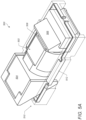
- FIGS. 5A-5C each illustrate a respective view of yet another example camera 500 having a folded optics arrangement and an example actuator arrangement for shifting a lens group of the camera 500 along multiple axes.
- FIG. 5A shows a perspective view of some structural components of the camera 500.
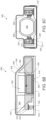
- FIG. 5B shows a schematic side cross-sectional view of the camera 500.
- FIG. 5C shows a schematic front cross-sectional view of the camera 500.
- the AF coil 524 may be oriented such that directions of current flow through the AF coil 524 define a plane that is substantially parallel to a surface of the fixed structure 514 (e.g., the surface on which the AF magnet 522 is mounted) and/or substantially parallel to the X-Y plane.
- the AF magnet 522 and the AF coil 524 may be located proximate one another, and the AF coil 524 may be electrically driven to magnetically interact with the AF magnet 522 to produce Lorentz forces that move the AF coil 524, the magnet holder 512, and/or the lens group 502 along an axis (e.g., along the X-axis) to provide AF movement.
- the OIS-X VCM actuator 620 may include one or more OIS-X coils 630.
- the OIS-X coils 630 may be attached to the lens barrel 608.
- each OIS-X coil 630 may be located between a respective shared OIS magnet 626 and the lens group 602.
- the OIS-X coils 630 may be electrically driven to magnetically interact with the shared OIS magnets 626 to produce Lorentz forces that move the OIS-X coils 630, the lens barrel 608, and the lens group 602 along an axis (e.g., along the Z-axis), relative to the magnet holder 612 and/or the fixed structure 614, to provide OIS-X movement.
- each of the shared OIS magnets 626 may have respective longest dimensions that are substantially parallel to respective longest dimensions of the OIS-X coils 630. In some embodiments, the respective longest dimensions of the shared OIS magnets 626 and the OIS-X coils 630 may be substantially parallel to a longest dimension of the system. Furthermore, the respective longest dimensions of the shared OIS magnets 626 and the OIS-X coils 630 may be substantially orthogonal to the respective longest dimensions of the AF magnet 622 and the AF coil 624 in some embodiments.
- the OIS-X coils 630 may be oriented such that directions of current flow through the OIS-X coils 630 define a respective plane that is substantially orthogonal to a surface of the fixed structure 614 (e.g., the surface on which the OIS-Y coils 628 are mounted).
- FIGS. 7A-7B each illustrate a respective view of still yet another example camera 700 having a folded optics arrangement and an example actuator arrangement for shifting a lens group of the camera 700 along multiple axes.
- FIG. 7A shows a schematic side cross-sectional view of the camera 700.
- FIG. 7B shows a schematic front cross-sectional view of the camera 700.
- the camera 700 includes a lens group 702, a first prism 704, and a second prism 706, and an image sensor (not shown).
- the lens group 702 may include one or more lens elements disposed within a lens barrel 708.
- the camera 700 may include a lens carrier 710 configured to hold the lens barrel 708 and/or the lens group 702.
- the camera 700 includes an actuator module 712 that provides for shifting the lens group 702 along multiple axes, e.g., to provide AF and/or OIS movement.
- the actuator module 712 may comprise a voice coil motor (VCM) actuator module that includes one or more VCM actuators.
- VCM voice coil motor
- the actuator module 712 may include one or more magnets and one or more coils. The magnets and coils may magnetically interact (e.g., when electrical current is provided to the coils) to produce Lorentz forces that move the lens group 702.
- the camera 700 may include multiple components (e.g., the lens barrel 708 in which one or more lens elements of the lens group 702 may be fixed, the lens carrier 710 that holds the lens barrel 708, etc.) that collectively holds the lens group 702 and one or more portions (e.g., one or more coils) of the actuator module 712, and that collectively couples with the magnet holder 714 (e.g., via suspension elements).
- the lens carrier 710 may be further subdivided into individual connected components in some embodiments.
- One or more coils may be coupled to the inner carrier structure (e.g., to the lens carrier 710).
- one or more magnets may be coupled to the outer carrier structure (e.g., to the magnet holder 714).
- the magnet holder 714 may extend at least partially around the first prism 704, at least partially around the lens carrier 710 (and the lens group 702), and/or at least partially around the second prism 706.
- the magnet holder 714 may extend at least partially around the lens carrier 710 and the first prism 704.
- the magnet holder 714 may be U-shaped in some embodiments.
- a first portion of the magnet holder 714 may extend proximate a first side of the lens carrier 710
- a second portion of the magnet holder 714 e.g., the second side of the magnet holder 714
- a third portion of the magnet holder 714 e.g., the third side of the magnet holder 714 may be tucked under a portion of the first prism 704 and may extend from the first portion to the second portion, e.g., as shown in FIGS. 7A-7B .
- the actuator module 712 may include one or more AF VCM actuators and/or one or more OIS VCM actuators.
- the actuator module 712 may include an AF VCM actuator 718 (e.g., to provide AF movement), an OIS-Y VCM actuator 720 (e.g., to provide OIS-Y movement), and an OIS-X VCM actuator 722 (e.g., to provide OIS-X movement).
- the AF VCM actuator 718 may include one or more magnets and one or more coils.
- the AF VCM actuator 718 may include an AF magnet 724 (e.g., a single-pole magnet) and an AF coil 726.
- the AF magnet 724 may be attached to the fixed structure 716.
- the AF coil 726 may be attached to the magnet holder 714.
- the AF magnet 724 may have a longest dimension that is substantially parallel to a longest dimension of the AF coil 726.
- the AF coil 726 may be oriented such that directions of current flow through the AF coil 726 define a plane that is substantially parallel to a surface of the fixed structure 716 (e.g., the surface on which the AF magnet 724 is mounted) and/or substantially parallel to the X-Y plane.
- the AF magnet 724 and the AF coil 726 may be located proximate one another, and the AF coil 726 may be electrically driven to magnetically interact with the AF magnet 724 to produce Lorentz forces that move the AF coil 726, the magnet holder 714, and/or the lens group 702 along an axis (e.g., along the X-axis) to provide AF movement.
- the OIS-Y VCM actuator 720 and the OIS-X VCM actuator 722 may share one or more OIS magnets 728.
- the shared OIS magnets 728 may be dual-pole magnets.
- the shared OIS magnets 728 may be attached to the magnet holder 714, e.g., at opposing sides of the lens group 702, as shown in FIGS. 7A and 7B .
- the OIS-X coils 732 may be oriented such that directions of current flow through the OIS-X coils 732 define a respective plane that is substantially orthogonal to a surface of the fixed structure 716 (e.g., the surface on which the OIS-Y coils 730 are mounted).
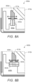
- FIG. 8A illustrates an example autofocus (AF) actuator 800a, e.g., for a camera having a folded optics arrangement.
- the AF actuator 800a may be a voice coil motor (VCM) actuator.
- the AF actuator 800a may include a single-pole magnet 802a and a coil 804a.
- the single-pole magnet 802a may be attached to a fixed structure 806a of the camera.
- the coil 804a may be attached to a magnet holder 808a of the camera.
- the AF actuator 800a may be tucked within a space under a portion of a first prism 810a, e.g., as indicated in FIG. 8A .
- the magnet holder 808a may have a portion 812a that faces the first prism 810a and that is shaped (e.g., chamfered, beveled, etc.) to reduce space consumed by the magnet holder 808a under the first prism 810a.
- the shape of the portion 812a may allow the magnet holder 808a to have an increased range of movement under the first prism 810a and/or may reduce the likelihood of contact between the magnet holder 808a and the first prism 810a.
- the magnet 802a may have a longest dimension (e.g., along the Y-axis) that is substantially parallel to a longest dimension of the coil 804a.
- the coil 804a may be oriented such that directions of current flow through the coil 804a define a plane that is substantially parallel to a surface of the fixed structure 806a (e.g., the surface on which the magnet 802a is mounted) and/or substantially parallel to the X-Y plane.
- the coil 804a may be located above the magnet 802a.
- FIG. 8B illustrates another example AF actuator 800b, e.g., for a camera having a folded optics arrangement.
- the AF actuator 800b may be a voice coil motor (VCM) actuator.
- the AF actuator 800b may include a dual-pole magnet 802b and a coil 804b.
- the dual-pole magnet 802b may be attached to a fixed structure 806b of the camera.
- the coil 804b may be attached to a magnet holder 808b of the camera.
- the AF actuator 800b may be tucked within a space under a portion of a first prism 810b, e.g., as indicated in FIG. 8B .
- the magnet holder 808b may have a portion 812b that faces the first prism 810b and that is shaped (e.g., chamfered, beveled, etc.) to reduce space consumed by the magnet holder 808b under the first prism 810b.
- the shape of the portion 812b may allow the magnet holder 808b to have an increased range of movement under the first prism 810b and/or may reduce the likelihood of contact between the magnet holder 808b and the first prism 810b.
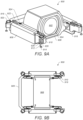
- FIGS. 9A-9D each illustrates a respective view of an example suspension arrangement 900 for a camera having a folded optics arrangement.
- FIG. 9A shows a perspective view of the suspension arrangement 900.
- FIG. 9B shows a top view of the suspension arrangement 900.
- FIG. 9C shows a top detail view of a portion of the suspension arrangement 900.
- FIG. 9D shows a bottom detail view of a portion of the suspension arrangement 900.
- the lens carrier 906 (and/or lens barrel 904) may be suspended from a magnet holder 908 via the suspension arrangement 900. Additionally, or alternatively, the magnet holder 908 may be suspended from a fixed structure (not shown) via the suspension arrangement 900.
- the suspension arrangement 900 may allow the lens carrier 906 to move relative to the magnet holder 908. Furthermore, the suspension arrangement 900 may allow the lens carrier 906 to move together with the magnet holder 908 relative to the fixed structure.
- the suspension arrangement 900 may include a set of one or more top springs 910 (not shown in FIG. 9D ) attached to respective top corner portions of the magnet holder 908 and the lens carrier 906.
- FIGS. 9A-9B show four top springs 910, each of which includes a respective first end that is attached to a respective corner portion of the magnet holder 908, and a second end that is attached to a corresponding corner portion of the lens carrier 906 (e.g., a corner portion of the lens carrier 906 that is located proximate the respective corner portion of the magnet holder 908).
- a respective suspension wire 912 may extend downward from each of the top springs 910.
- a bottom end portion 914 of the respective suspension wire 910 may be attached to a fixed (or static) structure, e.g., a fixed base structure of the camera.
- a fixed (or static) structure e.g., a fixed base structure of the camera.
- any number of the top springs 910 may be connected such that they form a single piece of material having individual portions that can independently flex. Reducing the number of individual pieces in this manner may be desirable from a manufacturing standpoint.
- one or more lens elements of the lens group 902 may define an optical axis that is substantially parallel to a plane defined by the set of top springs 910. Additionally, or alternatively, the optical axis may be substantially parallel to a plane defined by the set of bottom springs 916. Furthermore, a plane defined by the set of top springs 910 may be substantially parallel to a plane defined by the set of bottom springs 916. In some instances, the suspension wires 912 may extend in directions that are substantially orthogonal to the optical axis, a plane defined by the set of top springs 910, and/or a plane defined by the set of bottom springs 916.
- the suspension arrangement 900 may provide compliance and/or stiffness for controlled movement of the lens carrier 906 and/or the magnet holder 908.
- the suspension wires 912 may flex to allow controlled AF movement (e.g., along the X-axis) and/or OIS-Y movement (e.g., along the Y-axis) of the magnet holder 908 together with the lens carrier 906.
- the set of top springs 910 and/or the set of bottom springs 916 may not flex (or may flex substantially less than the suspension wires 912).
- the suspension wires 912 may provide compliance for such AF and/or OIS-Y movement in a controlled manner, and may provide sufficient stiffness to resist X-Y plane movement of the lens carrier (and the lens group 102) during OIS-X movement.
- the set of top springs 910 and/or the set of bottom springs 916 may flex to allow controlled OIS-X movement (e.g., the Z-axis) of the lens carrier 906 relative to the magnet holder 908. In some instances, e.g., during such OIS-X movement, the suspension wires 912 may not flex (or may flex substantially less than the set of top springs 910 and/or the set of bottom springs 916).
- the top springs 910 and/or the bottom springs 916 may provide compliance for such OIS-X movement in a controlled manner, and may provide sufficient stiffness to resist Z-axis movement of the lens carrier 906 (and the lens group 902) during OIS-Y and/or AF movement.
- an insertion needle (not shown) may be inserted through the hole in the base structure to access the pocket and inject the viscoelastic material 918 into the pocket.
- the protrusions 928 may extend from corner portions of the magnet holder 908, e.g., as shown in FIG. 9A . While FIG. 9A shows protrusions 928 that form pockets configured to contain, at least in part, the viscoelastic material 926, it should be understood that the viscoelastic material 926 may be disposed within pockets formed differently, e.g., via pockets formed of protrusions from a structure other than the magnet holder 908, pockets formed via a combination of the magnet holder 908 and one or more other structures, etc.
- the viscoelastic material 926 may be located along any portion(s) of the length of a suspension wire 912. In some embodiments, the viscoelastic material 926 may be located along a central portion of the length of a suspension wire 912.
- the suspension arrangement 900 may be used to carry signals (e.g., power and/or control signals) from the fixed structure of the camera to the magnet holder 908 and/or the lens carrier 906.
- suspension wires 912 may carry the signals from the fixed structure to top springs 910.
- the top springs 910 may carry the signals (e.g., via first portion 920 and fixed portion 918) from the suspension wires 912 to the magnet holder 908, and the signals may be routed to one or more coils attached to the magnet holder 908.
- the top springs 910 may carry the signals (e.g., via second portion 922 and fixed portion 924) from the suspension wires 912 to the lens carrier 906, and the signals may be routed to one or more coils attached to the lens carrier 906.
- Various portions of the suspension arrangement, the magnet holder 908, and/or the lens carrier 906 may be formed of electrically conductive material and/or may include electrical traces for carrying/routing the signals, e.g., from the fixed structure to the coils.
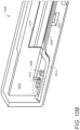
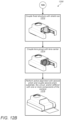
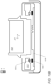
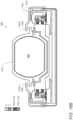
- FIGS. 10A-10E each illustrates a respective view of an example position sensor arrangement 1000 for a camera having a folded optics arrangement.
- FIG. 10A shows a perspective view of the position sensor arrangement 1000.
- the position sensor arrangement 1000 may include position sensors for position sensing with respect to AF movement, OIS-Y movement, and OIS-X movement.
- FIG. 10B shows a detail view that focuses on position sensing with respect to AF movement.
- FIGS. 10C-10D each shows a respective detail view that focuses on position sensing with respect to OIS-Y movement.
- FIG. 10E shows a detail view that focuses on position sensing with respect to OIS-X movement.
- the position sensor arrangement 1000 may include an AF movement position sensor arrangement 1002, an OIS-Y movement position sensor arrangement 1004, and/or an OIS-X movement position sensor arrangement 1006.
- the AF movement position sensor arrangement 1002 may include one or more AF position sensors 1008 and one or more corresponding AF probe magnets 1010.
- the AF position sensors 1008 may be magnetic field sensors (e.g., Hall sensors, tunneling magnetoresistance (TMR) sensors, giant magnetoresistance (GMR) sensors, etc.) in various embodiments.
- An AF position sensor 1008 may be disposed proximate a corresponding AF probe magnet 1010 such that the AF position sensor 1008 is capable of sensing one or more magnetic field components of the corresponding AF probe magnet 1010, e.g., as the AF probe magnet 1010 moves relative to the AF position sensor 1008.
- the AF movement position sensor arrangement 1002 may include two AF position sensors 1008 and two corresponding AF probe magnets 1010.
- a first AF position sensor 1008 and a first corresponding AF probe magnet 1010 may form a first pair.
- a second AF position sensor 1008 and a second corresponding AF probe magnet 1010 may form a second pair that is opposite the first pair with respect to the system X-axis, e.g., as indicated in FIG. 10A .
- rotation about the system Z-axis due to system X-axis displacement may be cancelled out in some embodiments.
- the OIS-X movement position sensor arrangement 1006 may include two OIS-X position sensors 1024 and two corresponding OIS-X probe magnets 1026.
- a first OIS-X position sensor 1024 and a first corresponding OIS-X probe magnet 1026 may form a first pair.
- a second OIS-X position sensor 1024 and a second corresponding OIS-X probe magnet 1026 may form a second pair that is opposite the first pair with respect to the system X-axis, e.g., as indicated in FIGS. 10A and 10E .
- rotation about the system Z-axis (due to system Z-axis displacement) and/or external field effects may be cancelled out in some embodiments.
- the camera 1100 may include a stiffener 1108 at least partially below the flex circuit 1106.
- the stiffener 1108 may be a folded stiffener, e.g., as shown in FIG. 11 .
- the folded stiffener 1108 may include a base portion below the flex circuit 1106 and tab portions that are each folded from the base portion to cover a respective side of the camera 1100 and/or the shield can 1102.
- the folded stiffener 1108 may include three tab portions, with each tab portion covering a portion of a respective one of three sides of the camera 1100 and/or the shield can 1102.
- a fourth side of the camera 1100 and/or the shield can 1102 may not have a corresponding tab portion that covers a portion of it.
- the fourth side may be a side at which the flex circuit 1106 extends outwardly to one or more components that are external to the camera 1100.
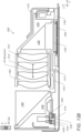
- the camera 1300 includes a lens group 1302, a first prism 1304, a second prism 1306, and an image sensor 1308 (shown in FIG. 13B ).
- the lens group 1302 may include one or more lens elements 1310 disposed within a lens barrel 1312.
- the camera 1300 includes an actuator module that provides for shifting the lens group 1302 along multiple axes, e.g., to provide AF and/or OIS movement.
- the actuator module may comprise a voice coil motor (VCM) actuator module that includes one or more VCM actuators.
- VCM voice coil motor
- the actuator module may include one or more magnets and one or more coils. The magnets and coils may magnetically interact (e.g., when electrical current is provided to the coils) to produce Lorentz forces that move the lens group 1302.
- the fourth side may be a proximal/image side extending along the Y-axis, and may be positioned in front of at least a portion of the reflecting surface side of the second prism 1306 (e.g., such that the second prism 1306 is disposed between the lens group 1302 and the magnet holder 1316).
- the magnet holder 1316 may encircle the optical elements of the folded optics arrangement (e.g., the first prism 1304, the lens group 1302, and the second prism 1306).
- a first portion of the magnet holder 1316 may extend proximate a first side of the lens carrier 1314
- a second portion of the magnet holder 1316 e.g., the second side of the magnet holder 1316) may extend proximate a second side of the lens carrier 1314 that is opposite the first side of the lens carrier 1314
- a third portion of the magnet holder 1316 e.g., the third side of the magnet holder 1316) may be tucked under a portion of the first prism 1304, and a fourth portion of the magnet holder 1316 (e.g., the fourth side of the magnet holder 1316) may extend in front of the second prism 1306.
- the actuator module may include one or more AF VCM actuators and/or one or more OIS VCM actuators.
- the actuator module may include an AF VCM actuator 1320 (e.g., to provide AF movement, as indicated in FIG. 13B ), an OIS-Y VCM actuator 1322 (e.g., to provide OIS-Y movement, as indicated in FIG. 13C ), and an OIS-X VCM actuator 1324 (e.g., to provide OIS-X movement, as indicated in FIG. 13C ).
- the AF VCM actuator 1320 may include one or more magnets and one or more coils.
- the AF VCM actuator 1320 may include an AF magnet 1326 (e.g., a dual-pole magnet) and an AF coil 1328.
- the AF magnet 1326 may be attached to the fixed structure 1318.
- a first portion of the AF magnet 1326 may have a N-S polarity in a first direction
- a second portion of the AF magnet 1326 may have a N-S polarity in a second direction that is opposite the first direction, e.g., as indicated by the N-S polarity directions shown in FIG. 13B .
- the first portion may be parallel to the second portion in some embodiments.
- the AF coil 1328 may be attached to the magnet holder 1316.
- the AF magnet 1326 may have a longest dimension (e.g., along the Y-axis) that is substantially parallel to a longest dimension (e.g., along the Y-axis) of the AF coil 1328.
- the AF coil 1328 may be oriented such that directions of current flow through the AF coil 1328 define a plane that is parallel to the X-Y plane.
- the AF magnet 1326 and the AF coil 1328 may be located proximate one another, and the AF coil 1328 may be electrically driven to magnetically interact with the AF magnet 1326 to produce Lorentz forces that move the AF coil 1328, the magnet holder 1316, and/or the lens group 1302 along an axis (e.g., along the X-axis) to provide AF movement (e.g., movement that shifts an image projected on the image sensor in one or more directions parallel to the Z-axis).
- the AF magnet 1326 being attached to the fixed structure 1318, may remain stationary relative to the movement of the AF coil 1328.
- the AF VCM actuator 1320 may be tucked within a space under a portion of the first prism 1304, e.g., as indicated in FIG. 13B . In this manner, the impact of the AF VCM actuator 1320 on the dimension of the system along its long axis (e.g., the X-axis) and along its vertical axis (e.g., the Z-axis) may be reduced or eliminated.
- the OIS-Y VCM actuator 1322 may include one or more OIS-Y coils 1332.
- the OIS-Y coils 1332 may be attached to the fixed structure 1318.
- each OIS-Y coil 1332 may be located below a respective shared OIS magnet 1330.
- the OIS-Y coils 1332 may be electrically driven to magnetically interact with the shared OIS magnets 1330 to produce Lorentz forces that move the shared OIS magnets 1330, the magnet holder 1316, and/or the lens group 1302 along an axis (e.g., along the Y-axis) to provide OIS-Y movement (e.g., movement that shifts an image projected on the image sensor in one or more directions parallel to the Y-axis).
- each of the shared OIS magnets 1330 may have respective longest dimensions (e.g., along the X-axis) that are substantially parallel to respective longest dimensions (e.g., along the X-axis) of the OIS-Y coils 1332.
- the respective longest dimensions of the shared OIS magnets 1330 and the OIS-Y coils 1332 may be substantially parallel to a longest dimension (e.g., along the X-axis) of the system.
- the respective longest dimensions of the shared OIS magnets 1330 and the OIS-Y coils 1332 may be substantially orthogonal to the respective longest dimensions of the AF magnet 1326 and the AF coil 1328 in some embodiments.
- the OIS-Y coils 1332 may be oriented such that directions of current flow through the OIS-Y coils 1332 define a respective plane that is parallel to the X-Y plane.
- the OIS-X VCM actuator 1324 may include one or more OIS-X coils 1334.
- the OIS-X coils 1334 may be attached to the lens carrier 1314.
- each OIS-X coil 1334 may be located between a respective shared OIS magnet 1330 and the lens group 1302.
- the OIS-X coils 1334 may be electrically driven to magnetically interact with the shared OIS magnets 1330 to produce Lorentz forces that move the OIS-X coils 1334, the lens carrier 1314, and the lens group 1302 along an axis (e.g., along the Z-axis), relative to the magnet holder 1316 and/or the fixed structure 1318, to provide OIS-X movement (e.g., movement that shifts an image projected on the image sensor in one or more directions parallel to the X-axis).
- OIS-X movement e.g., movement that shifts an image projected on the image sensor in one or more directions parallel to the X-axis.
- each of the shared OIS magnets 1330 may have respective longest dimensions (e.g., along the X-axis) that are substantially parallel to respective longest dimensions (e.g., along the X-axis) of the OIS-X coils 1334.
- the respective longest dimensions of the shared OIS magnets 1330 and the OIS-X coils 1334 may be substantially parallel to a longest dimension (e.g., along the X-axis) of the system.
- the respective longest dimensions of the shared OIS magnets 1330 and the OIS-X coils 1334 may be substantially orthogonal to the respective longest dimensions of the AF magnet 1326 and the AF coil 1328 in some embodiments.
- the camera 1300 may include a first prism holder 1340 (shown in FIG. 13A ) that holds the first prism 1304.
- the first prism 1304 may be attached to one or more fixed structures of the camera 1300 via the first prism holder 1340.
- the camera 1300 may include a second prism holder 1342 that holds the second prism 1306.
- the second prism 1342 may be attached to one or more fixed structures of the camera 1300 via the second prism holder 1342.
- the camera 1400 may include an AF VCM actuator 1410 that is located under the first prism 1404.
- the AF VCM actuator 1410 (and other components near it) may be located within a first space beneath a first portion of the first prism 1404, leaving a second space (e.g., as generally indicated by dashed rectangle 1412) as available free space (space that is not consumed by the camera 1400) beneath a second portion of the first prism 1404.
- the first space (and the first portion) may be located (along the X-axis) between the lens group 1402 and the second space 1412 (and the second portion).
- a system may include multiple cameras.
- the system may include the camera 1400 and a second camera (not shown) that is adjacent to the camera 1400. At least a portion of the second camera may be disposed within the second space 1412 described above. In this manner, the camera 1400 may partially overlap with the second camera, and the dimension of the multi-camera system along the X-axis may be reduced.
- the multi-camera system may have more than two cameras in some embodiments. According to some examples, the cameras may be the same. In other embodiments, one or more cameras of the system may be different than one or more other cameras of the system.
- the AF movement position sensor arrangement 1502 may include one or more AF position sensors 1508 and one or more corresponding AF probe magnets 1510, e.g., as shown in FIGS. 15A and 15B .
- the AF position sensors 1508 may be magnetic field sensors (e.g., Hall sensors, tunneling magnetoresistance (TMR) sensors, giant magnetoresistance (GMR) sensors, etc.) in various embodiments.
- the OIS-X probe magnet 1526 of the first pair may have a N-S polarity direction that is opposite that of the OIS-X probe magnet 1526 of the second pair.
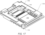
- FIG. 17 illustrates a bottom perspective view of an example base structure 1700 (e.g., for a camera having a folded optics arrangement, such as those described above) having an example base bridge 1702 that provides structural support to the base structure 1700.
- a substrate 1704 may be attached to the base structure 1700.
- An image sensor 1706 may be attached to the substrate 1704.
- a flex circuit board 1708 may be attached to the base structure 1700.
- an undesirable bending deformation may occur at one substrate side near the center, near a window/open area, and/or near an image sensor, e.g., during a drop event.
- the base bridge 1702 described here may be used to reinforce the window area and provide structural support to the substrate 1704 so as to reduce or prevent undesirable bending deformation.
- the base bridge 1702 may extend (e.g., along the Y-axis) proximate a side of the substrate 1704 and/or proximate the image sensor 1706.
- an electronic device that includes a display and a touch-sensitive surface is described. It should be understood, however, that the electronic device may include one or more other physical user-interface devices, such as a physical keyboard, a mouse and/or a joystick.
- the device typically supports a variety of applications, such as one or more of the following: a drawing application, a presentation application, a word processing application, a website creation application, a disk authoring application, a spreadsheet application, a gaming application, a telephone application, a video conferencing application, an e-mail application, an instant messaging application, a workout support application, a photo management application, a digital camera application, a digital video camera application, a web browsing application, a digital music player application, and/or a digital video player application.
- applications such as one or more of the following: a drawing application, a presentation application, a word processing application, a website creation application, a disk authoring application, a spreadsheet application, a gaming application, a telephone application, a video conferencing application, an e-mail application, an instant messaging application, a workout support application, a photo management application, a digital camera application, a digital video camera application, a web browsing application, a digital music player application, and/or a digital video player application.
- the various applications that may be executed on the device may use at least one common physical user-interface device, such as the touch-sensitive surface.
- One or more functions of the touch-sensitive surface as well as corresponding information displayed on the device may be adjusted and/or varied from one application to the next and/or within a respective application.
- a common physical architecture (such as the touch-sensitive surface) of the device may support the variety of applications with user interfaces that are intuitive and transparent to the user.
- FIG. 18 illustrates a block diagram of an example portable multifunction device 1800 that may include one or more cameras (e.g., the cameras described above with reference to FIGS. 1-16 ), in accordance with some embodiments.
- Cameras 1864 are sometimes called “optical sensors” for convenience, and may also be known as or called an optical sensor system.
- Device 1800 may include memory 1802 (which may include one or more computer readable storage mediums), memory controller 1822, one or more processing units (CPUs) 1820, peripherals interface 1818, RF circuitry 1808, audio circuitry 1810, speaker 1811, touch-sensitive display system 1812, microphone 1813, input/output (I/O) subsystem 1806, other input or control devices 1816, and external port 1824.
- Device 1800 may include multiple optical sensors 1864. These components may communicate over one or more communication buses or signal lines 1803.
- device 1800 is only one example of a portable multifunction device, and that device 1800 may have more or fewer components than shown, may combine two or more components, or may have a different configuration or arrangement of the components.
- the various components shown in FIG. 18 may be implemented in hardware, software, or a combination of hardware and software, including one or more signal processing and/or application specific integrated circuits.
- Memory 1802 may include high-speed random access memory and may also include non-volatile memory, such as one or more magnetic disk storage devices, flash memory devices, or other non-volatile solid-state memory devices. Access to memory 1802 by other components of device 1800, such as CPU 1820 and the peripherals interface 1818, may be controlled by memory controller 1822.
- Peripherals interface 1818 can be used to couple input and output peripherals of the device to CPU 1820 and memory 1802.
- the one or more processors 1820 run or execute various software programs and/or sets of instructions stored in memory 1802 to perform various functions for device 1800 and to process data.
- peripherals interface 1818, CPU 1820, and memory controller 1822 may be implemented on a single chip, such as chip 1804. In some other embodiments, they may be implemented on separate chips.
- RF (radio frequency) circuitry 1808 receives and sends RF signals, also called electromagnetic signals.
- RF circuitry 1808 converts electrical signals to/from electromagnetic signals and communicates with communications networks and other communications devices via the electromagnetic signals.
- RF circuitry 1808 may include well-known circuitry for performing these functions, including but not limited to an antenna system, an RF transceiver, one or more amplifiers, a tuner, one or more oscillators, a digital signal processor, a CODEC chipset, a subscriber identity module (SIM) card, memory, and so forth.
- SIM subscriber identity module
- RF circuitry 1808 may communicate with networks, such as the Internet, also referred to as the World Wide Web (WWW), an intranet and/or a wireless network, such as a cellular telephone network, a wireless local area network (LAN) and/or a metropolitan area network (MAN), and other devices by wireless communication.
- networks such as the Internet, also referred to as the World Wide Web (WWW), an intranet and/or a wireless network, such as a cellular telephone network, a wireless local area network (LAN) and/or a metropolitan area network (MAN), and other devices by wireless communication.
- networks such as the Internet, also referred to as the World Wide Web (WWW), an intranet and/or a wireless network, such as a cellular telephone network, a wireless local area network (LAN) and/or a metropolitan area network (MAN), and other devices by wireless communication.
- WLAN wireless local area network
- MAN metropolitan area network
- the wireless communication may use any of a variety of communications standards, protocols and technologies, including but not limited to Global System for Mobile Communications (GSM), Enhanced Data GSM Environment (EDGE), high-speed downlink packet access (HSDPA), high-speed uplink packet access (HSUPA), wideband code division multiple access (W-CDMA), code division multiple access (CDMA), time division multiple access (TDMA), Bluetooth, Wireless Fidelity (Wi-Fi) (e.g., IEEE 802.11a, IEEE 802.11b, IEEE 802.11g and/or IEEE 802.11n), voice over Internet Protocol (VoIP), Wi-MAX, a protocol for e-mail (e.g., Internet message access protocol (IMAP) and/or post office protocol (POP)), instant messaging (e.g., extensible messaging and presence protocol (XMPP), Session Initiation Protocol for Instant Messaging and Presence Leveraging Extensions (SIMPLE), Instant Messaging and Presence Service (IMPS)), and/or Short Message Service (SMS), or any
- Audio circuitry 1810, speaker 1811, and microphone 1813 provide an audio interface between a user and device 1800.
- Audio circuitry 1810 receives audio data from peripherals interface 1818, converts the audio data to an electrical signal, and transmits the electrical signal to speaker 1811.
- Speaker 1811 converts the electrical signal to human-audible sound waves.
- Audio circuitry 1810 also receives electrical signals converted by microphone 1813 from sound waves.
- Audio circuitry 1810 converts the electrical signal to audio data and transmits the audio data to peripherals interface 1818 for processing. Audio data may be retrieved from and/or transmitted to memory 1802 and/or RF circuitry 1808 by peripherals interface 1818.
- audio circuitry 1810 also includes a headset jack (e.g., 1912, FIG. 19 ).
- the headset jack provides an interface between audio circuitry 1810 and removable audio input/output peripherals, such as output-only headphones or a headset with both output (e.g., a headphone for one or both ears) and input (e.g., a microphone).
- removable audio input/output peripherals such as output-only headphones or a headset with both output (e.g., a headphone for one or both ears) and input (e.g., a microphone).
- I/O subsystem 1806 couples input/output peripherals on device 1800, such as touch screen 1812 and other input control devices 1816, to peripherals interface 1818.
- I/O subsystem 1806 may include display controller 1856 and one or more input controllers 1860 for other input or control devices.
- the one or more input controllers 1860 receive/send electrical signals from/to other input or control devices 1816.
- the other input control devices 1816 may include physical buttons (e.g., push buttons, rocker buttons, etc.), dials, slider switches, joysticks, click wheels, and so forth.
- input controller(s) 1860 may be coupled to any (or none) of the following: a keyboard, infrared port, USB port, and a pointer device such as a mouse.
- the one or more buttons may include an up/down button for volume control of speaker 1811 and/or microphone 1813.
- the one or more buttons may include a push button (e.g., 1906, FIG. 19 ).
- Touch-sensitive display 1812 provides an input interface and an output interface between the device and a user.
- Display controller 1856 receives and/or sends electrical signals from/to touch screen 1812.
- Touch screen 1812 displays visual output to the user.
- the visual output may include graphics, text, icons, video, and any combination thereof (collectively termed "graphics"). In some embodiments, some or all of the visual output may correspond to user-interface objects.
- Touch screen 1812 has a touch-sensitive surface, sensor or set of sensors that accepts input from the user based on haptic and/or tactile contact.
- Touch screen 1812 and display controller 1856 (along with any associated modules and/or sets of instructions in memory 1802) detect contact (and any movement or breaking of the contact) on touch screen 1812 and converts the detected contact into interaction with user-interface objects (e.g., one or more soft keys, icons, web pages or images) that are displayed on touch screen 1812.
- user-interface objects e.g., one or more soft keys, icons, web pages or images
- a point of contact between touch screen 1812 and the user corresponds to a finger of the user.
- Touch screen 1812 may use LCD (liquid crystal display) technology, LPD (light emitting polymer display) technology, or LED (light emitting diode) technology, although other display technologies may be used in other embodiments.
- Touch screen 1812 and display controller 1856 may detect contact and any movement or breaking thereof using any of a variety of touch sensing technologies now known or later developed, including but not limited to capacitive, resistive, infrared, and surface acoustic wave technologies, as well as other proximity sensor arrays or other elements for determining one or more points of contact with touch screen 1812.
- touch sensing technologies now known or later developed, including but not limited to capacitive, resistive, infrared, and surface acoustic wave technologies, as well as other proximity sensor arrays or other elements for determining one or more points of contact with touch screen 1812.
- projected mutual capacitance sensing technology is used, such as that found in the iPhone ® , iPod Touch ® , and iPad ® from Apple Inc. of Cupertino, California.
- Touch screen 1812 may have a video resolution in excess of 800 dpi. In some embodiments, the touch screen has a video resolution of approximately 860 dpi.
- the user may make contact with touch screen 1812 using any suitable object or appendage, such as a stylus, a finger, and so forth.
- the user interface is designed to work primarily with finger-based contacts and gestures, which can be less precise than stylus-based input due to the larger area of contact of a finger on the touch screen.
- the device translates the rough finger-based input into a precise pointer/cursor position or command for performing the actions desired by the user.
- device 1800 may include a touchpad (not shown) for activating or deactivating particular functions.
- the touchpad is a touch-sensitive area of the device that, unlike the touch screen, does not display visual output.
- the touchpad may be a touch-sensitive surface that is separate from touch screen 1812 or an extension of the touch-sensitive surface formed by the touch screen.
- Power system 1862 for powering the various components.
- Power system 1862 may include a power management system, one or more power sources (e.g., battery, alternating current (AC)), a recharging system, a power failure detection circuit, a power converter or inverter, a power status indicator (e.g., a light-emitting diode (LED)) and any other components associated with the generation, management and distribution of power in portable devices.
- power sources e.g., battery, alternating current (AC)
- AC alternating current
- a recharging system e.g., a recharging system
- a power failure detection circuit e.g., a power failure detection circuit
- a power converter or inverter e.g., a power converter or inverter
- a power status indicator e.g., a light-emitting diode (LED)
- Device 1800 may also include one or more optical sensors or cameras 1864.
- FIG. 18 shows an optical sensor 1864 coupled to optical sensor controller 1858 in I/O subsystem 1806.
- Optical sensor 1864 may include charge-coupled device (CCD) or complementary metal-oxide semiconductor (CMOS) phototransistors.
- CMOS complementary metal-oxide semiconductor
- Optical sensor 1864 receives light from the environment, projected through one or more lens, and converts the light to data representing an image.
- imaging module 1843 also called a camera module
- optical sensor 1864 may capture still images or video.
- an optical sensor 1864 is located on the back of device 1800, opposite touch screen display 1812 on the front of the device, so that the touch screen display 1812 may be used as a viewfinder for still and/or video image acquisition.
- another optical sensor is located on the front of the device so that the user's image may be obtained for videoconferencing while the user views the other video conference participants on the touch screen display.
- Operating system 1826 (e.g., Darwin, RTXC, LINUX, UNIX, OS X, WINDOWS, or an embedded operating system such as VxWorks) includes various software components and/or drivers for controlling and managing general system tasks (e.g., memory management, storage device control, power management, etc.) and facilitates communication between various hardware and software components.
- general system tasks e.g., memory management, storage device control, power management, etc.
- Graphics module 1832 includes various known software components for rendering and displaying graphics on touch screen 1812 or other display, including components for changing the intensity of graphics that are displayed.
- graphics includes any object that can be displayed to a user, including without limitation text, web pages, icons (such as user-interface objects including soft keys), digital images, videos, animations and the like.
- Text input module 1834 which may be a component of graphics module 1832, provides soft keyboards for entering text in various applications (e.g., contacts 1837, e-mail 1840, IM 1841, browser 1847, and any other application that needs text input).
- applications e.g., contacts 1837, e-mail 1840, IM 1841, browser 1847, and any other application that needs text input).
- GPS module 1835 determines the location of the device and provides this information for use in various applications (e.g., to telephone 1838 for use in location-based dialing, to camera 1843 as picture/video metadata, and to applications that provide location-based services such as weather widgets, local yellow page widgets, and map/navigation widgets).
- applications e.g., to telephone 1838 for use in location-based dialing, to camera 1843 as picture/video metadata, and to applications that provide location-based services such as weather widgets, local yellow page widgets, and map/navigation widgets).
- Applications 1836 may include the following modules (or sets of instructions), or a subset or superset thereof:
- Examples of other applications 1836 that may be stored in memory 1802 include other word processing applications, other image editing applications, drawing applications, presentation applications, JAVA-enabled applications, encryption, digital rights management, voice recognition, and voice replication.
- contacts module 1837 may be used to manage an address book or contact list (e.g., stored in application internal state 1857), including: adding name(s) to the address book; deleting name(s) from the address book; associating telephone number(s), e-mail address(es), physical address(es) or other information with a name; associating an image with a name; categorizing and sorting names; providing telephone numbers or e-mail addresses to initiate and/or facilitate communications by telephone 1838, video conference 1839, e-mail 1840, or IM 1841; and so forth.
- an address book or contact list e.g., stored in application internal state 1857
- telephone module 1838 may be used to enter a sequence of characters corresponding to a telephone number, access one or more telephone numbers in address book 1837, modify a telephone number that has been entered, dial a respective telephone number, conduct a conversation and disconnect or hang up when the conversation is completed.
- the wireless communication may use any of a variety of communications standards, protocols and technologies.
- the instant messaging module 1841 includes executable instructions to enter a sequence of characters corresponding to an instant message, to modify previously entered characters, to transmit a respective instant message (for example, using a Short Message Service (SMS) or Multimedia Message Service (MMS) protocol for telephony-based instant messages or using XMPP, SIMPLE, or IMPS for Internet-based instant messages), to receive instant messages and to view received instant messages.
- SMS Short Message Service
- MMS Multimedia Message Service
- XMPP extensible Markup Language
- SIMPLE Session Initiation Protocol
- IMPS Internet Messaging Protocol
- transmitted and/or received instant messages may include graphics, photos, audio files, video files and/or other attachments as are supported in a MMS and/or an Enhanced Messaging Service (EMS).
- EMS Enhanced Messaging Service
- instant messaging refers to both telephony-based messages (e.g., messages sent using SMS or MMS) and Internet-based messages (e.g., messages sent using XMPP
- image management module 1844 includes executable instructions to arrange, modify (e.g., edit), or otherwise manipulate, label, delete, present (e.g., in a digital slide show or album), and store still and/or video images.
- modify e.g., edit
- present e.g., in a digital slide show or album
- browser module 1847 includes executable instructions to browse the Internet in accordance with user instructions, including searching, linking to, receiving, and displaying web pages or portions thereof, as well as attachments and other files linked to web pages.
- calendar module 1848 includes executable instructions to create, display, modify, and store calendars and data associated with calendars (e.g., calendar entries, to do lists, etc.) in accordance with user instructions.
- widget modules 1849 are mini-applications that may be downloaded and used by a user (e.g., weather widget 549-1, stocks widget 549-2, calculator widget 1849-3, alarm clock widget 1849-4, and dictionary widget 1849-5) or created by the user (e.g., user-created widget 1849-6).
- a widget includes an HTML (Hypertext Markup Language) file, a CSS (Cascading Style Sheets) file, and a JavaScript file.
- a widget includes an XML (Extensible Markup Language) file and a JavaScript file (e.g., Yahoo! Widgets).
- the widget creator module 1850 may be used by a user to create widgets (e.g., turning a user-specified portion of a web page into a widget).
- search module 1851 includes executable instructions to search for text, music, sound, image, video, and/or other files in memory 1802 that match one or more search criteria (e.g., one or more user-specified search terms) in accordance with user instructions.
- search criteria e.g., one or more user-specified search terms
- video and music player module 1852 includes executable instructions that allow the user to download and play back recorded music and other sound files stored in one or more file formats, such as MP3 or AAC files, and executable instructions to display, present or otherwise play back videos (e.g., on touch screen 1812 or on an external, connected display via external port 1824).
- device 1800 may include the functionality of an MP3 player.
- notes module 1853 includes executable instructions to create and manage notes, to do lists, and the like in accordance with user instructions.
- map module 1854 may be used to receive, display, modify, and store maps and data associated with maps (e.g., driving directions; data on stores and other points of interest at or near a particular location; and other location-based data) in accordance with user instructions.
- maps e.g., driving directions; data on stores and other points of interest at or near a particular location; and other location-based data
- online video module 1855 includes instructions that allow the user to access, browse, receive (e.g., by streaming and/or download), play back (e.g., on the touch screen or on an external, connected display via external port 1824), send an e-mail with a link to a particular online video, and otherwise manage online videos in one or more file formats, such as H.264.
- instant messaging module 1841 rather than e-mail client module 1840, is used to send a link to a particular online video.
- modules and applications correspond to a set of executable instructions for performing one or more functions described above and the methods described in this application (e.g., the computer-implemented methods and other information processing methods described herein).
- modules i.e., sets of instructions
- memory 1802 may store a subset of the modules and data structures identified above.
- memory 1802 may store additional modules and data structures not described above.
- device 1800 is a device where operation of a predefined set of functions on the device is performed exclusively through a touch screen and/or a touchpad.
- a touch screen and/or a touchpad as the primary input control device for operation of device 1800, the number of physical input control devices (such as push buttons, dials, and the like) on device 1800 may be reduced.
- the predefined set of functions that may be performed exclusively through a touch screen and/or a touchpad include navigation between user interfaces.
- the touchpad when touched by the user, navigates device 1800 to a main, home, or root menu from any user interface that may be displayed on device 1800.
- the touchpad may be referred to as a "menu button.”
- the menu button may be a physical push button or other physical input control device instead of a touchpad.
- FIG. 19 depicts illustrates an example portable multifunction device 1800 that may include one or more cameras (e.g., the cameras described above with reference to FIGS. 1-16B ), in accordance with some embodiments.
- the device 1800 may have a touch screen 1812.
- the touch screen 1812 may display one or more graphics within user interface (UI) 1900.
- UI user interface
- a user may select one or more of the graphics by making a gesture on the graphics, for example, with one or more fingers 1902 (not drawn to scale in the figure) or one or more styluses 1903 (not drawn to scale in the figure).
- Device 1800 may also include one or more physical buttons, such as "home" or menu button 1904.
- menu button 1904 may be used to navigate to any application 1836 in a set of applications that may be executed on device 1800.
- the menu button 1904 is implemented as a soft key in a GUI displayed on touch screen 1812.
- device 1800 includes touch screen 1812, menu button 1904, push button 1906 for powering the device on/off and locking the device, volume adjustment button(s) 1908, Subscriber Identity Module (SIM) card slot 1910, head set jack 1912, and docking/charging external port 1924.
- Push button 1906 may be used to turn the power on/off on the device by depressing the button and holding the button in the depressed state for a predefined time interval; to lock the device by depressing the button and releasing the button before the predefined time interval has elapsed; and/or to unlock the device or initiate an unlock process.
- device 1800 also may accept verbal input for activation or deactivation of some functions through microphone 1813.
- optical sensor(s) / camera(s) 1864 on the front of a device
- one or more rear-facing cameras or optical sensors that are pointed opposite from the display may be used instead of, or in addition to, an optical sensor(s) / camera(s) 1864 on the front of a device.
Landscapes
- Physics & Mathematics (AREA)
- General Physics & Mathematics (AREA)
- Engineering & Computer Science (AREA)
- Optics & Photonics (AREA)
- Multimedia (AREA)
- Signal Processing (AREA)
- Software Systems (AREA)
- Theoretical Computer Science (AREA)
- General Engineering & Computer Science (AREA)
- Power Engineering (AREA)
- Electromagnetism (AREA)
- Combustion & Propulsion (AREA)
- Chemical & Material Sciences (AREA)
- Lens Barrels (AREA)
- Adjustment Of Camera Lenses (AREA)
- Studio Devices (AREA)
Description
- This disclosure relates generally to architecture for a camera with folded optics and lens shifting capabilities.
- The advent of small, mobile multipurpose devices such as smartphones and tablet or pad devices has resulted in a need for high-resolution, small form factor cameras for integration in the devices. Some small form factor cameras may incorporate optical image stabilization (OIS) mechanisms that may sense and react to external excitation/disturbance by adjusting location of the optical lens on the X and/or Y axis in an attempt to compensate for unwanted motion of the lens. Some small form factor cameras may incorporate an autofocus (AF) mechanism whereby the object focal distance can be adjusted to focus an object plane in front of the camera at an image plane to be captured by the image sensor. In some such autofocus mechanisms, the optical lens is moved as a single rigid body along the optical axis of the camera to refocus the camera.
-
WO 2017/037688 A1 describes a folded digital camera module comprising an optical path folding element (OPFE) for folding light from a first optical path with a first optical axis to a second optical path with a second optical axis perpendicular to the first optical axis, an image sensor, and a lens module carrying a lens with a symmetry axis parallel to the second optical axis. -
US 2012/314307 A1 describes a lens actuator that includes a carrier that is configured to retain a lens; a first AF coil that is disposed in the carrier while wound about an axis perpendicular to a lens retaining surface; first to fourth magnets that are disposed opposite the first AF coil in four directions parallel to the lens retaining surface; a first OIS coil that is disposed opposite the first magnet; and a second OIS coil that is disposed opposite the second magnet. -
-
FIG. 1 illustrates a perspective view of an example camera with a folded optics arrangement, in accordance with some embodiments. -
FIG. 2 illustrates an example of 3-axis movement of a lens group within a folded optics arrangement, in accordance with some embodiments. -
FIGS. 3A-3C each illustrate a respective view of an example camera having a folded optics arrangement and an example actuator arrangement for shifting a lens group of the camera along multiple axes, in accordance with some embodiments.FIG. 3A shows a perspective view of some structural components of the camera.FIG. 3B shows a schematic side cross-sectional view of the camera.FIG. 3C shows a schematic front cross-sectional view of the camera. -
FIGS. 4A-4B each illustrate a respective view of another example camera having a folded optics arrangement and an example actuator arrangement for shifting a lens group of the camera along multiple axes, in accordance with some embodiments.FIG. 4A shows a schematic side cross-sectional view of the camera.FIG. 4B shows a schematic front cross-sectional view of the camera. -
FIGS. 5A-5C each illustrate a respective view of yet another example camera having a folded optics arrangement and an example actuator arrangement for shifting a lens group of the camera along multiple axes, in accordance with some embodiments.FIG. 5A shows a perspective view of some structural components of the camera.FIG. 5B shows a schematic side cross-sectional view of the camera.FIG. 5C shows a schematic front cross-sectional view of the camera. -
FIGS. 6A-6C each illustrate a respective view of still yet another example camera having a folded optics arrangement and an example actuator arrangement for shifting a lens group of the camera along multiple axes, in accordance with some embodiments.FIG. 6A shows a perspective view of some structural components of the camera.FIG. 6B shows a schematic side cross-sectional view of the camera.FIG. 6C shows a schematic front cross-sectional view of the camera. -
FIGS. 7A-7B each illustrate a respective view of still yet another example camera having a folded optics arrangement and an example actuator arrangement for shifting a lens group of the camera along multiple axes, in accordance with some embodiments.FIG. 7A shows a schematic side cross-sectional view of the camera.FIG. 7B shows a schematic front cross-sectional view of the camera. -
FIG. 8A illustrates an example autofocus (AF) actuator, e.g., for a camera having a folded optics arrangement, in accordance with some embodiments. -
FIG. 8B illustrates another example AF actuator, e.g., for a camera having a folded optics arrangement, in accordance with some embodiments. -
FIGS. 9A-9D each illustrate a respective view of an example suspension arrangement for a camera having a folded optics arrangement, in accordance with some embodiments.FIG. 9A shows a perspective view of the suspension arrangement.FIG. 9B shows a top view of the suspension arrangement.FIG. 9C shows a top detail view of a portion of the suspension arrangement.FIG. 9D shows a bottom detail view of a portion of the suspension arrangement. -
FIGS. 10A-10E each illustrate a respective view of an example position sensor arrangement for a camera having a folded optics arrangement, in accordance with some embodiments.FIG. 10A shows a perspective view of the position sensor arrangement. The position sensor arrangement may include position sensors for position sensing with respect to AF movement, OIS-Y movement, and OIS-X movement.FIG. 10B shows a detail view that focuses on position sensing with respect to AF movement.FIGS. 10C-10D each shows a respective detail view that focuses on position sensing with respect to OIS-Y movement.FIG. 10E shows a detail view that focuses on position sensing with respect to OIS-X movement. -
FIG. 11 illustrates a perspective view of an example camera having a folded optics arrangement, with a shield can covering at least a portion of the internal components of the camera, in accordance with some embodiments. -
FIGS. 12A-12B illustrate a flow diagram of an example method for assembling a camera having a folded optics arrangement, in accordance with some embodiments. -
FIGS. 13A-13C each illustrate a respective view of another example camera having a folded optics arrangement and an example actuator arrangement for shifting a lens group of the camera along multiple axes, in accordance with some embodiments.FIG. 13A shows a perspective view of some structural components of the camera.FIG. 13B shows a schematic side cross-sectional view of the camera.FIG. 3C shows a schematic front cross-sectional view of the camera. -
FIG. 14 illustrates an example camera that has a folded optics arrangement and that has a lower portion with a reduced dimension along the X-axis (e.g., as compared to that of the camera ofFIGS. 13A-13C ), in accordance with some embodiments. -
FIGS. 15A-15C each illustrate a respective view of another example position sensor arrangement for a camera having a folded optics arrangement, in accordance with some embodiments.FIG. 15A shows a perspective view of the position sensor arrangement. The position sensor arrangement may include position sensors for position sensing with respect to AF movement, OIS-X movement, and OIS-Y movement.FIG. 15B shows a cross-sectional view that focuses on position sensing with respect to AF movement.FIG. 15C shows a cross-sectional view that focuses on position sensing with respect to OIS-X and OIS-Y movement. -
FIGS. 16A-16B illustrate an example camera that has a folded optics arrangement and that includes a module can with retention elements, in accordance with some embodiments.FIG. 16A shows a perspective view of the camera.FIG. 16B shows a cross-sectional view of the camera. -
FIG. 17 illustrates an example base structure (e.g., for a camera having a folded optics arrangement) that includes a base bridge, in accordance with some embodiments. -
FIG. 18 illustrates a block diagram of an example portable multifunction device that may include a camera having a folded optics arrangement, in accordance with some embodiments. -
FIG. 19 depicts an example portable multifunction device that may include a camera having a folded optics arrangement, in accordance with some embodiments. -
FIG. 20 illustrates an example computer system that may include a camera having a folded optics arrangement, in accordance with some embodiments. - Some embodiments include camera equipment outfitted with controls, magnets, and voice coil motors to improve the effectiveness of a miniature actuation mechanism for a compact camera module. More specifically, in some embodiments, compact camera modules include actuators to deliver functions such as autofocus (AF) and/or optical image stabilization (OIS). One approach to delivering a very compact actuator for AF and/or OIS is to use a voice coil motor (VCM) actuator.
- Reference will now be made in detail to embodiments, examples of which are illustrated in the accompanying drawings. In the following detailed description, numerous specific details are set forth in order to provide a thorough understanding of the present disclosure. However, it will be apparent to one of ordinary skill in the art that some embodiments may be practiced without these specific details. In other instances, well-known methods, procedures, components, circuits, and networks have not been described in detail so as not to unnecessarily obscure aspects of the embodiments.
- Described here are folded optics arrangements for providing a reduced-height imaging system. The arrangements discussed throughout generally comprise one or more lenses positioned between two light path folding elements, which collectively provides a dual-folded light path. The one or more lenses are moveable between the light path folding elements to provide autofocus and/or image stabilization during imaging.
FIG. 1 shows a generalized example of acamera 100 with a folded optics arrangement The example X-Y-Z coordinate system shown inFIG. 1 is used to discuss aspects of systems and/or system components, and may apply to embodiments described throughout this disclosure. - In various embodiments, the
camera 100 includes alens group 102, afirst prism 104, asecond prism 106, and animage sensor package 108. Thelens group 102 includes one or more lens elements. In some embodiments, thelens group 102 is located between thefirst prism 104 and thesecond prism 106, forming the folded optics arrangement. Light may follow anoptical path 110 that is folded by thefirst prism 104 such that the light is directed towards thelens group 102, passes through thelens group 102, and is folded by thesecond prism 106 such that the light is directed towards theimage sensor package 108. In some examples, light may enter an object side of thefirst prism 104 along the Z-axis. Thefirst prism 104 may redirect the light to propagate along the X-axis (which may be parallel to an optical axis defined by the lens group 102) towards thelens group 102. Thesecond prism 106 may redirect the light to propagate along the Z-axis (which may be orthogonal to a plane defined by the image sensor package 108), e.g., such that the light exits an image side of thesecond prism 106 towards theimage sensor package 108. Thefirst prism 104, thelens group 102, and/or thesecond prism 106 are positioned along a common axis (e.g., the X-axis, the optical axis defined by thelens group 102, etc.). According to some examples, theoptical path 110 may be contained within a plane (e.g., the X-Z plane), and theimage sensor package 108 may extend along a different plane (e.g., the X-Y plane). - In some embodiments, the object side of the
first prism 104 may extend along the X-Y plane. Furthermore, thefirst prism 104 may include a pair of opposing lateral sides that each extend along the X-Z plane, a lens group facing side that extends along the Y-Z plane, and a reflecting surface side that is angled relative to one or more of the other sides of thefirst prism 104. For example, the reflecting surface side of thefirst prism 104 may include a reflective surface that is angled so as to redirect light received from the object side of thefirst prism 104 towards the lens group 102 (via the lens group facing side of the first prism 104), as discussed above. - In some embodiments, the image side of the
second prism 106 may extend along the X-Y plane, e.g., proximate theimage sensor package 108. Furthermore, thesecond prism 106 may include a pair of opposing lateral sides that each extend along the X-Z plane, a lens group facing side that extends along the Y-Z plane, and a reflecting surface side that is angled relative to one or more of the other sides of thesecond prism 106. For example, the reflecting surface side of thesecond prism 106 may include a reflective surface that is angled so as to redirect light received from the lens group 102 (via the lens group facing side of the second prism 106) towards the image sensor package (via the image side of the second prism 106), as discussed above. - While the light path folding elements are shown in various figures as comprising prisms (e.g., the
first prism 104 and the second prism 106), the camera systems and/or folded optics arrangements described herein may include any suitable light path folding element (e.g., a mirror or the like, which is not an embodiment of the invention) or combination of elements. In some embodiments, one or more of the light path folding elements may also act as a lens element (or combination of lens elements). For example, one or more lens elements (e.g., other than those of the lens group 102) may be integrated with the first prism 104 (and/or the second prism 106) such that the prism acts as a lens element. Additionally, or alternatively, the first prism 104 (and/or the second prism 106) may be shaped such that the prism acts as a lens element. - As will be discussed in further detail below, the
lens group 102 is coupled with an actuator structure that is configured to move thelens group 102 along multiple axes, e.g., to provide autofocus (AF) and/or optical image stabilization (OIS) functionality.FIG. 2 shows an example of 3-axis movement of thelens group 102 to provide AF and/or OIS functionality. For example, thelens group 102 may be shifted (e.g., by an actuator structure, such as the actuator structures/arrangements discussed in further detail below) along the X-axis to provide AF movement. Additionally, or alternatively, thelens group 102 may be shifted along the Z-axis to provide OIS-X movement (e.g., movement that shifts the image projected on theimage sensor package 108 in one or more directions parallel to the X-axis). Additionally, or alternatively, thelens group 102 may be shifted along the Y-axis to provide OIS-Y movement (e.g., movement that shifts the image projected on theimage sensor package 108 in one or more directions parallel to the Y-axis). Components of the camera 100 (e.g., thelens group 102, thefirst prism 104, thesecond prism 106, and/or theimage sensor package 108, etc.) may be used with any of the actuator arrangements described in the following figures. - As mentioned above, the camera systems described here comprises an actuator system to move the lens group relative to the light path folding elements (e.g., the
first prism 104 and the second prism 106). The actuator arrangements described here comprise more carrier structures (e.g., the inner carrier structures and the outer carrier structures of the carrier arrangements discussed below), one or more suspension structures for moveably holding the carrier structure(s) relative to the rest of the camera and/or for moveably holding a carrier structure relative to another carrier structure, and an actuator module for controlling movement of the carrier structure(s).FIGS. 3A-3C show perspective and cross-sectional views of one such variation, and include anexample camera 300 with a folded optics arrangement. - The
camera 300 includes alens group 302, afirst prism 304, asecond prism 306, and an image sensor (not shown). Thelens group 302 may include one ormore lens elements 308 disposed within alens barrel 310. - The
camera 300 includes anactuator module 312 that provides for shifting thelens group 302 along multiple axes, e.g., to provide AF and/or OIS movement. In some embodiments, theactuator module 312 may comprise a voice coil motor (VCM) actuator module that includes one or more VCM actuators. For instance, theactuator module 312 may include one or more magnets and one or more coils. The magnets and coils may magnetically interact (e.g., when electrical current is provided to the coils) to produce Lorentz forces that move thelens group 302. - The
camera 300 includes a carrier arrangement that includes an inner carrier structure (e.g., thelens barrel 310 and/or a lens carrier) and an outer carrier structure (e.g., amagnet holder 314 and/or a magnet frame). One or more coils may be coupled to the inner carrier structure (e.g., to thelens barrel 310 and/or a lens carrier). Furthermore, one or more magnets may be coupled to the outer carrier structure (e.g., to the magnet holder 314). In some embodiments, themagnet holder 314 may extend at least partially around thefirst prism 304, at least partially around the lens barrel 310 (and the lens group 302), and/or at least partially around thesecond prism 306. For instance, as shown inFIGS. 3A-3C , themagnet holder 314 may extend at least partially around thelens barrel 310 and thefirst prism 304. Themagnet holder 314 may be U-shaped in some embodiments. - The
magnet holder 314 may have multiple sides and/or portions. For example, themagnet holder 314 may have a first side, a second side, and a third side. The first side may be a lateral side extending along the X-axis and along the side surfaces of the optical elements. The second side may be a lateral side extending along the X-axis and along the opposite side surfaces of the optical elements. The third side may be a distal/object side extending along the Y-axis, and may be positioned behind at least a portion of the reflecting surface side of the first prism 304 (e.g., such that thefirst prism 304 is disposed between thelens group 302 and the magnet holder 314). - According to some examples, a first portion of the magnet holder 314 (e.g., the first side of the magnet holder 314) may extend proximate a first side of the
lens barrel 310, a second portion of the magnet holder 314 (e.g., the second side of the magnet holder 314) may extend proximate a second side of thelens barrel 310 that is opposite the first side of thelens barrel 310, and a third portion of the magnet holder 314 (e.g. the third side of the magnet holder 314) may be tucked under a portion of thefirst prism 304 and may extend from the first portion to the second portion, e.g., as shown inFIGS. 3A-3C . In some embodiments, the magnet holder 314 (and/or outer carrier structure) may have a different number of sides and/or a different combination of sides, e.g., as will be discussed below with reference to at leastFIGS. 4A-6C . WhileFIGS. 3A-3C show themagnet holder 314 partially encircling the optical elements of the folded optics arrangement (e.g., thefirst prism 304, thelens group 302, and the second prism 306), it is understood that themagnet holder 314 may encircle the optical elements (e.g., as shown inFIGS. 5A-5C ) in some embodiments. - As will be discussed below with reference to
FIGS. 9A-9D , thelens barrel 310 may be suspended from themagnet holder 314 via a suspension arrangement. Additionally, or alternatively, themagnet holder 314 may be suspended from a fixed (or static) structure (e.g., fixed structure 316) of thecamera 300 via the suspension arrangement. The suspension arrangement may allow thelens barrel 310 to move relative to themagnet holder 314. Furthermore, the suspension arrangement may allow thelens barrel 310 to move together with themagnet holder 314 relative to the fixedstructure 316. In various examples, thelens barrel 310 may be fixedly attached to thelens group 302, and movement of the lens barrel 310 (e.g., due to actuation of one or more actuators of the actuator module 312) may cause movement of thelens group 302, such that thelens group 302 moves together with thelens barrel 310. According to some embodiments, the fixedstructure 316 may include a component of thecamera 300 to which the carrier arrangement is moveably connected (e.g., via suspension elements). The fixedstructure 316 may be fixed relative to movement of the carrier arrangement. Furthermore, the fixedstructure 316 may be fixed relative to thefirst prism 304, thesecond prism 306, and/or the image sensor. In some examples, the fixedstructure 316 may include multiple components that are joined or otherwise fixed relative to each other. - In various embodiments, the
actuator module 312 may include one or more AF VCM actuators and/or one or more OIS VCM actuators. In some embodiments, theactuator module 312 may include an AF VCM actuator 318 (e.g., to provide AF movement), an OIS-Y VCM actuator 320 (e.g., to provide OIS-Y movement), and an OIS-X VCM actuator 322 (e.g., to provide OIS-X movement). - The
AF VCM actuator 318 may include one or more magnets and one or more coils. In some examples, theAF VCM actuator 318 may include an AF magnet 324 (e.g., a single-pole magnet) and anAF coil 326. TheAF magnet 324 may be attached to the fixedstructure 316. TheAF coil 326 may be attached to themagnet holder 314. In some embodiments, theAF magnet 324 may have a longest dimension that is substantially parallel to a longest dimension of theAF coil 326. In some embodiments, theAF coil 326 may be oriented such that directions of current flow through theAF coil 326 define a plane that is substantially parallel to a surface of the fixed structure 316 (e.g., the surface on which theAF magnet 324 is mounted) and/or substantially parallel to the X-Y plane. TheAF magnet 324 and theAF coil 326 may be located proximate one another, and theAF coil 326 may be electrically driven to magnetically interact with theAF magnet 324 to produce Lorentz forces that move theAF coil 326, themagnet holder 314, and/or thelens group 302 along an axis (e.g., along the X-axis) to provide AF movement (e.g., movement that shifts an image projected on the image sensor in one or more directions parallel to the Z-axis). TheAF magnet 324, being attached to the fixedstructure 316, may remain stationary relative to the movement of theAF coil 326. In various embodiments, theAF VCM actuator 318 may be tucked within a space under a portion of thefirst prism 304, e.g., as indicated inFIG. 3B . In this manner, the impact of theAF VCM actuator 318 on the dimension of the system along its long axis (e.g., the X-axis) and along its vertical axis (e.g., the Z-axis) may be reduced or eliminated. - In some embodiments, the OIS-
Y VCM actuator 320 and the OIS-X VCM actuator 322 may share one or more OIS magnets 328 (also referred to herein as "shared OIS magnets"). In some embodiments, the sharedOIS magnets 328 may be dual-pole magnets. The sharedOIS magnets 328 may be attached to themagnet holder 314, e.g., at opposing sides of thelens group 302, as shown inFIGS. 3B and 3C . - According to some examples, the OIS-Y VCM actuator 320 may include one or more OIS-Y coils 330. The OIS-Y coils 330 may be attached to the fixed
structure 316. In some embodiments, each OIS-Y coil 330 may be located below a respective sharedOIS magnet 328. The OIS-Y coils 330 may be electrically driven to magnetically interact with the sharedOIS magnets 328 to produce Lorentz forces that move the sharedOIS magnets 328, themagnet holder 314, and/or thelens group 302 along an axis (e.g., along the Y-axis) to provide OIS-Y movement (e.g., movement that shifts an image projected on the image sensor in one or more directions parallel to the Y-axis). The OIS-Y coils 330, being attached to the fixedstructure 316, may remain stationary relative to the movement of the sharedOIS magnets 328. In some embodiments, each of the sharedOIS magnets 328 may have respective longest dimensions that are substantially parallel to respective longest dimensions of the OIS-Y coils 330. In some embodiments, the respective longest dimensions of the sharedOIS magnets 328 and the OIS-Y coils 330 may be substantially parallel to a longest dimension of the system. Furthermore, the respective longest dimensions of the sharedOIS magnets 328 and the OIS-Y coils 330 may be substantially orthogonal to the respective longest dimensions of theAF magnet 324 and theAF coil 326 in some embodiments. According to various embodiments, the OIS-Y coils 330 may be oriented such that directions of current flow through the OIS-Y coils 330 define a respective plane that is substantially parallel to a surface of the fixed structure 316 (e.g., the surface on which the OIS-Y coils 330 are mounted). - According to some examples, the OIS-
X VCM actuator 322 may include one or more OIS-X coils 332. The OIS-X coils 332 may be attached to thelens barrel 310. In some embodiments, each OIS-X coil 332 may be located between a respective sharedOIS magnet 328 and thelens group 302. The OIS-X coils 332 may be electrically driven to magnetically interact with the sharedOIS magnets 328 to produce Lorentz forces that move the OIS-X coils 332, thelens barrel 310, and thelens group 302 along an axis (e.g., along the Z-axis), relative to themagnet holder 314 and/or the fixedstructure 316, to provide OIS-X movement (e.g., movement that shifts an image projected on the image sensor in one or more directions parallel to the X-axis). In some embodiments, each of the sharedOIS magnets 328 may have respective longest dimensions that are substantially parallel to respective longest dimensions of the OIS-X coils 332. In some embodiments, the respective longest dimensions of the sharedOIS magnets 328 and the OIS-X coils 332 may be substantially parallel to a longest dimension of the system. Furthermore, the respective longest dimensions of the sharedOIS magnets 328 and the OIS-X coils 332 may be substantially orthogonal to the respective longest dimensions of theAF magnet 324 and theAF coil 326 in some embodiments. According to various embodiments, the OIS-X coils 332 may be oriented such that directions of current flow through the OIS-X coils 332 define a respective plane that is substantially orthogonal to a surface of the fixed structure 316 (e.g., the surface on which the OIS-Y coils 330 are mounted). - In various embodiments, the
camera 300 may include a substrate below thesecond prism 306. An image sensor may be coupled to the substrate. In some embodiments, a filter (e.g., an infrared filter) may also be coupled to the substrate. For instance, the filter may be located above the image sensor such that light passes through the filter before reaching the image sensor. In some examples, the substrate may be parallel to the fixedstructure 316. Additionally, or alternatively, the fixedstructure 316 may include the substrate and/or one or more other components. - In some embodiments, the
camera 300 may include a first prism holder 334 that holds thefirst prism 304. In some embodiments, thefirst prism 304 may be attached to one or more fixed (or static) structures of thecamera 300 via the first prism holder 334. For instance, the first prism holder 334 may be attached to a shield can 336 in some cases. Additionally, or alternatively, thecamera 300 may include a second prism holder 338 that holds thesecond prism 306. In some embodiments, thesecond prism 306 may be attached to one or more fixed (or static) structures of thecamera 300 via the second prism holder 338. For instance, the second prism holder 338 may be attached to the shield can 336 in some cases. -
FIGS. 4A-4B each illustrate a respective view of anotherexample camera 400 having a folded optics arrangement and an example actuator arrangement for shifting a lens group of thecamera 400 along multiple axes.FIG. 4A shows a schematic side cross-sectional view of thecamera 400.FIG. 4B shows a schematic front cross-sectional view of thecamera 400. - The
camera 400 includes alens group 402, afirst prism 404, and asecond prism 406, and an image sensor (not shown). Thelens group 402 may include one or more lens elements disposed within alens barrel 408. - The
camera 400 includes anactuator module 410 that provides for shifting thelens group 402 along multiple axes, e.g., to provide AF and/or OIS movement. In some embodiments, theactuator module 410 may comprise a voice coil motor (VCM) actuator module that includes one or more VCM actuators. For instance, theactuator module 410 may include one or more magnets and one or more coils. The magnets and coils may magnetically interact (e.g., when electrical current is provided to the coils) to produce Lorentz forces that move thelens group 402. - The
camera 400 includes a carrier arrangement that includes an inner carrier structure (e.g., thelens barrel 408 and/or a lens carrier) and an outer carrier structure (e.g., amagnet holder 412 and/or a magnet frame). One or more coils may be coupled to the inner carrier structure (e.g., to thelens barrel 408 and/or a lens carrier). Furthermore, one or more magnets may be coupled to the outer carrier structure (e.g., to the magnet holder 412). In some embodiments, themagnet holder 412 may extend at least partially around thefirst prism 404, at least partially around the lens barrel 408 (and the lens group 402), and/or at least partially around thesecond prism 406. For instance, as shown inFIGS. 4A-4B , themagnet holder 412 may extend at least partially around thelens barrel 408 and thesecond prism 406. Themagnet holder 412 may be U-shaped in some embodiments. - The
magnet holder 412 may have multiple sides and/or portions. For example, themagnet holder 412 may have a first side, a second side, and a third side. The first side may be a lateral side extending along the X-axis and along the side surface of the optical elements. The second side may be a lateral side extending along the X-axis and along the opposite side surface of the optical elements. The third side may be a proximal/image side extending along the Y-axis, and may be positioned in front of at least a portion of the reflecting surface side of the second prism 406 (e.g., such that thesecond prism 406 is disposed between thelens group 402 and the magnet holder 412). - According to some examples, a first portion of the magnet holder 412 (e.g., the first side of the magnet holder 412) may extend proximate a first side of the
lens barrel 408, a second portion of the magnet holder 412 (e.g., the second side of the magnet holder 412) may extend proximate a second side of thelens barrel 408 that is opposite the first side of thelens barrel 408, and a third portion of the magnet holder 412 (e.g., the third side of the magnet holder 412) may extend in front of a portion of thesecond prism 406, e.g., as shown inFIGS. 4A-4B . As will be discussed below with reference toFIGS. 9A-9D , thelens barrel 408 may be suspended from themagnet holder 412 via a suspension arrangement. Additionally, or alternatively, themagnet holder 412 may be suspended from a fixedstructure 414 of thecamera 400 via the suspension arrangement. The suspension arrangement may allow thelens barrel 408 to move relative to themagnet holder 412. Furthermore, the suspension arrangement may allow thelens barrel 408 to move together with themagnet holder 412 relative to the fixedstructure 414. - In various embodiments, the
actuator module 410 may include one or more AF VCM actuators and/or one or more OIS VCM actuators. In some embodiments, theactuator module 410 may include an AF VCM actuator 416 (e.g., to provide AF movement), an OIS-Y VCM actuator 418 (e.g., to provide OIS-Y movement), and an OIS-X VCM actuator 420 (e.g., to provide OIS-X movement). - The
AF VCM actuator 416 may include one or more magnets and one or more coils. In some examples, theAF VCM actuator 416 may include an AF magnet 422 (e.g., a single-pole magnet) and anAF coil 424. TheAF magnet 422 may be attached to themagnet holder 412. TheAF coil 424 may be attached to the fixedstructure 414. In some embodiments, theAF magnet 422 may have a longest dimension that is substantially parallel to a longest dimension of theAF coil 424. In some embodiments, theAF coil 424 may be oriented such that directions of current flow through theAF coil 424 define a plane that is substantially parallel to a surface of the fixed structure 414 (e.g., the surface on which theAF coil 424 is mounted) and/or substantially parallel to the X-Y plane. TheAF magnet 422 and theAF coil 424 may be located proximate one another, and theAF coil 424 may be electrically driven to magnetically interact with theAF magnet 422 to produce Lorentz forces that move theAF magnet 422, themagnet holder 412, and/or thelens group 402 along an axis (e.g., along the X-axis) to provide AF movement. TheAF coil 424, being attached to the fixedstructure 414, may remain stationary relative to the movement of theAF magnet 422. In various embodiments, theAF VCM actuator 416 may be located in front of a portion of the second 406, e.g., as indicated inFIG. 4A . - In some embodiments, the OIS-
Y VCM actuator 418 and the OIS-X VCM actuator 420 may share one ormore OIS magnets 426. In some embodiments, the sharedOIS magnets 426 may be dual-pole magnets. The sharedOIS magnets 426 may be attached to themagnet holder 412, e.g., at opposing sides of thelens group 402, as shown inFIGS. 4A and 4B . - According to some examples, the OIS-Y VCM actuator 418 may include one or more OIS-Y coils 428. The OIS-Y coils 428 may be attached to the fixed
structure 414. In some embodiments, each OIS-Y coil 428 may be located below a respective sharedOIS magnet 426. The OIS-Y coils 428 may be electrically driven to magnetically interact with the sharedOIS magnets 426 to produce Lorentz forces that move the sharedOIS magnets 426, themagnet holder 412, and/or thelens group 402 along an axis (e.g., along the Y-axis) to provide OIS-Y movement. The OIS-Y coils 428, being attached to the fixedstructure 414, may remain stationary relative to the movement of the sharedOIS magnets 426. In some embodiments, each of the sharedOIS magnets 426 may have respective longest dimensions that are substantially parallel to respective longest dimensions of the OIS-Y coils 428. In some embodiments, the respective longest dimensions of the sharedOIS magnets 426 and the OIS-Y coils 428 may be substantially parallel to a longest dimension of the system. Furthermore, the respective longest dimensions of the sharedOIS magnets 426 and the OIS-Y coils 428 may be substantially orthogonal to the respective longest dimensions of theAF magnet 422 and theAF coil 424 in some embodiments. According to various embodiments, the OIS-Y coils 428 may be oriented such that directions of current flow through the OIS-Y coils 428 define a respective plane that is substantially parallel to a surface of the fixed structure 414 (e.g., the surface on which the OIS-Y coils 428 are mounted). - According to some examples, the OIS-
X VCM actuator 420 may include one or more OIS-X coils 430. The OIS-X coils 430 may be attached to thelens barrel 408. In some embodiments, each OIS-X coil 430 may be located between a respective sharedOIS magnet 426 and thelens group 402. The OIS-X coils 430 may be electrically driven to magnetically interact with the sharedOIS magnets 426 to produce Lorentz forces that move the OIS-X coils 430, thelens barrel 408, and thelens group 402 along an axis (e.g., along the Z-axis), relative to themagnet holder 412 and/or the fixedstructure 414, to provide OIS-X movement. In some embodiments, each of the sharedOIS magnets 426 may have respective longest dimensions that are substantially parallel to respective longest dimensions of the OIS-X coils 430. In some embodiments, the respective longest dimensions of the sharedOIS magnets 426 and the OIS-X coils 430 may be substantially parallel to a longest dimension of the system. Furthermore, the respective longest dimensions of the sharedOIS magnets 426 and the OIS-X coils 430 may be substantially orthogonal to the respective longest dimensions of theAF magnet 422 and theAF coil 424 in some embodiments. According to various embodiments, the OIS-X coils 430 may be oriented such that directions of current flow through the OIS-X coils 430 define a respective plane that is substantially orthogonal to a surface of the fixed structure 414 (e.g., the surface on which the OIS-Y coils 428 are mounted). -
FIGS. 5A-5C each illustrate a respective view of yet anotherexample camera 500 having a folded optics arrangement and an example actuator arrangement for shifting a lens group of thecamera 500 along multiple axes.FIG. 5A shows a perspective view of some structural components of thecamera 500.FIG. 5B shows a schematic side cross-sectional view of thecamera 500.FIG. 5C shows a schematic front cross-sectional view of thecamera 500. - In some embodiments, the
camera 500 may include alens group 502, afirst prism 504, and asecond prism 506, and an image sensor (not shown). Thelens group 502 may include one or more lens elements disposed within alens barrel 508. - The
camera 500 includes anactuator module 510 that provides for shifting thelens group 502 along multiple axes, e.g., to provide AF and/or OIS movement. In some embodiments, theactuator module 510 may comprise a voice coil motor (VCM) actuator module that includes one or more VCM actuators. For instance, theactuator module 510 may include one or more magnets and one or more coils. The magnets and coils may magnetically interact (e.g., when electrical current is provided to the coils) to produce Lorentz forces that move thelens group 502. - The
camera 500 includes a carrier arrangement that includes an inner carrier structure (e.g., thelens barrel 508 and/or a lens carrier) and an outer carrier structure (e.g., amagnet holder 512 and/or a magnet frame). One or more coils may be coupled to the inner carrier structure (e.g., to thelens barrel 508 and/or a lens carrier). Furthermore, one or more magnets may be coupled to the outer carrier structure (e.g., to the magnet holder 512). In some embodiments, themagnet holder 512 may extend at least partially around thefirst prism 504, the lens barrel 508 (and the lens group 502), and thesecond prism 506, e.g., as shown inFIGS. 5A-5C . - The
magnet holder 512 may have multiple sides and/or portions. For example, themagnet holder 512 may have a first side, a second side, a third side, and a fourth side. The first side may be a lateral side extending along the X-axis and along the side surfaces of the optical elements. The second side may be a lateral side extending along the X-axis and along the opposite side surfaces of the optical elements. The third side may be a distal/object side extending along the Y-axis, and may be positioned behind at least a portion of the reflecting surface side of the first prism 504 (e.g., such that thefirst prism 504 is disposed between thelens group 502 and the magnet holder 512). The fourth side may be a proximal/image side extending along the Y-axis, and may be positioned in front of at least a portion of the reflecting surface side of the second prism 506 (e.g., such that thesecond prism 506 is disposed between thelens group 502 and the magnet holder 512). In some non-limiting examples, themagnet holder 512 may encircle the optical elements of the folded optics arrangement (e.g., thefirst prism 504, thelens group 502, and the second prism 506). In some examples, one or more of the sides of themagnet holder 512 may comprise two parts that are spaced apart from each other by a gap, so that themagnet holder 512 partially encircles the optical elements. - According to some examples, a first portion of the magnet holder 512 (e.g,. the first side of the magnet holder 512) may extend proximate a first side of the
lens barrel 508, a second portion of the magnet holder 512 (e.g., the second side of the magnet holder 512) may extend proximate a second side of thelens barrel 508 that is opposite the first side of thelens barrel 508, a third portion of the magnet holder 512 (e.g., the third side of the magnet holder 512) may be tucked under a portion of thefirst prism 504, and a fourth portion of the magnet holder 512 (e.g., the fourth side of the magnet holder 512) may extend in front of thesecond prism 506. As will be discussed below with reference toFIGS. 9A-9D , thelens barrel 508 may be suspended from themagnet holder 512 via a suspension arrangement. Additionally, or alternatively, themagnet holder 512 may be suspended from a fixedstructure 514 of thecamera 500 via the suspension arrangement. The suspension arrangement may allow thelens barrel 508 to move relative to themagnet holder 512. Furthermore, the suspension arrangement may allow thelens barrel 508 to move together with themagnet holder 512 relative to the fixedstructure 514. - In various embodiments, the
actuator module 510 may include one or more AF VCM actuators and/or one or more OIS VCM actuators. In some embodiments, theactuator module 510 may include an AF VCM actuator 516 (e.g., to provide AF movement), an OIS-Y VCM actuator 518 (e.g., to provide OIS-Y movement), and an OIS-X VCM actuator 520 (e.g., to provide OIS-X movement). - The
AF VCM actuator 516 may include one or more magnets and one or more coils. In some examples, theAF VCM actuator 516 may include an AF magnet 522 (e.g., a single-pole magnet) and anAF coil 524. TheAF magnet 522 may be attached to the fixedstructure 514. TheAF coil 524 may be attached to themagnet holder 512. In some embodiments, theAF magnet 522 may have a longest dimension that is substantially parallel to a longest dimension of theAF coil 524. In some embodiments, theAF coil 524 may be oriented such that directions of current flow through theAF coil 524 define a plane that is substantially parallel to a surface of the fixed structure 514 (e.g., the surface on which theAF magnet 522 is mounted) and/or substantially parallel to the X-Y plane. TheAF magnet 522 and theAF coil 524 may be located proximate one another, and theAF coil 524 may be electrically driven to magnetically interact with theAF magnet 522 to produce Lorentz forces that move theAF coil 524, themagnet holder 512, and/or thelens group 502 along an axis (e.g., along the X-axis) to provide AF movement. TheAF magnet 522, being attached to the fixedstructure 514, may remain stationary relative to the movement of theAF coil 524. In various embodiments, theAF VCM actuator 516 may be tucked within a space under a portion of thefirst prism 504, e.g., as indicated inFIG. 5B . In this manner, the impact of theAF VCM actuator 516 on the dimension of the system along the system X-axis and along the system Z-axis may be reduced or eliminated. - In some embodiments, the OIS-
Y VCM actuator 518 and the OIS-X VCM actuator 520 may share one ormore OIS magnets 526. In some embodiments, the sharedOIS magnets 526 may be dual-pole magnets. The sharedOIS magnets 526 may be attached to themagnet holder 512, e.g., at opposing sides of thelens group 502, as shown inFIGS. 5B and 5C . - According to some examples, the OIS-Y VCM actuator 518 may include one or more OIS-Y coils 528. The OIS-Y coils 528 may be attached to the fixed
structure 514. In some embodiments, each OIS-Y coil 528 may be located below a respective sharedOIS magnet 526. The OIS-Y coils 528 may be electrically driven to magnetically interact with the sharedOIS magnets 526 to produce Lorentz forces that move the sharedOIS magnets 526, themagnet holder 512, and/or thelens group 502 along an axis (e.g., along the Y-axis) to provide OIS-Y movement. The OIS-Y coils 528, being attached to the fixedstructure 514, may remain stationary relative to the movement of the sharedOIS magnets 526. In some embodiments, each of the sharedOIS magnets 526 may have respective longest dimensions that are substantially parallel to respective longest dimensions of the OIS-Y coils 528. In some embodiments, the respective longest dimensions of the sharedOIS magnets 526 and the OIS-Y coils 528 may be substantially parallel to a longest dimension of the system. Furthermore, the respective longest dimensions of the sharedOIS magnets 526 and the OIS-Y coils 528 may be substantially orthogonal to the respective longest dimensions of theAF magnet 522 and theAF coil 524 in some embodiments. According to various embodiments, the OIS-Y coils 528 may be oriented such that directions of current flow through the OIS-Y coils 528 define a respective plane that is substantially parallel to a surface of the fixed structure 514 (e.g., the surface on which the OIS-Y coils 528 are mounted). - According to some examples, the OIS-
X VCM actuator 520 may include one or more OIS-X coils 530. The OIS-X coils 530 may be attached to thelens barrel 508. In some embodiments, each OIS-X coil 530 may be located between a respective sharedOIS magnet 526 and thelens group 502. The OIS-X coils 530 may be electrically driven to magnetically interact with the sharedOIS magnets 526 to produce Lorentz forces that move the OIS-X coils 530, thelens barrel 508, and thelens group 502 along an axis (e.g., along the Z-axis), relative to themagnet holder 512 and/or the fixedstructure 514, to provide OIS-X movement. In some embodiments, each of the sharedOIS magnets 526 may have respective longest dimensions that are substantially parallel to respective longest dimensions of the OIS-X coils 530. In some embodiments, the respective longest dimensions of the sharedOIS magnets 526 and the OIS-X coils 530 may be substantially parallel to a longest dimension of the system. Furthermore, the respective longest dimensions of the sharedOIS magnets 526 and the OIS-X coils 530 may be substantially orthogonal to the respective longest dimensions of theAF magnet 522 and theAF coil 524 in some embodiments. According to various embodiments, the OIS-X coils 530 may be oriented such that directions of current flow through the OIS-X coils 530 define a respective plane that is substantially orthogonal to a surface of the fixed structure 514 (e.g., the surface on which the OIS-Y coils 528 are mounted). -
FIGS. 6A-6C each illustrate a respective view of still yet anotherexample camera 600 having a folded optics arrangement and an example actuator arrangement for shifting a lens group of thecamera 600 along multiple axes.FIG. 6A shows a perspective view of some structural components of thecamera 600.FIG. 6B shows a schematic side cross-sectional view of thecamera 600.FIG. 6C shows a schematic front cross-sectional view of thecamera 600. - The
camera 600 includes alens group 602, afirst prism 604, and asecond prism 606, and an image sensor (not shown). Thelens group 602 may include one or more lens elements disposed within alens barrel 608. - The
camera 600 includes anactuator module 610 that provides for shifting thelens group 602 along multiple axes, e.g., to provide AF and/or OIS movement. In some embodiments, theactuator module 610 may comprise a voice coil motor (VCM) actuator module that includes one or more VCM actuators. For instance, theactuator module 610 may include one or more magnets and one or more coils. The magnets and coils may magnetically interact (e.g., when electrical current is provided to the coils) to produce Lorentz forces that move thelens group 602. - The
camera 600 includes a carrier arrangement that includes an inner carrier structure (e.g., thelens barrel 608 and/or a lens carrier) and an outer carrier structure (e.g., amagnet holder 612 and/or a magnet frame). One or more coils may be coupled to the inner carrier structure (e.g., to thelens barrel 608 and/or a lens carrier). Furthermore, one or more magnets may be coupled to the outer carrier structure (e.g., to the magnet holder 612). In some embodiments, themagnet holder 612 may extend at least partially around thefirst prism 604, the lens barrel 608 (and the lens group 602), and thesecond prism 606, e.g., as shown inFIGS. 6A-6C . - The
magnet holder 612 may have multiple sides and/or portions. For example, themagnet holder 612 may have a first side, a second side, a third side, and a fourth side. The first side may be a lateral side extending along the X-axis and along the side surfaces of the optical elements. The second side may be a lateral side extending along the X-axis and along the opposite side surfaces of the optical elements. The third side may be a distal/object side extending along the Y-axis, and may be positioned behind at least a portion of the reflecting surface side of the first prism 604 (e.g., such that thefirst prism 604 is disposed between thelens group 602 and the magnet holder 612). The fourth side may be an upper side/portion extending above thelens group 602 and connecting the first side to the second side. In some embodiments, the fourth side may at least partially encompass an upper surface of the lens barrel 608 (and/or a lens carrier). Furthermore, in some embodiments, the fourth side may not encompass upper surfaces of thefirst prism 604 and/or thesecond prism 606. There may be gap between an upper surface of the lens barrel 608 (and/or a lens carrier). The gap may provide sufficient clearance to allow movement of the lens barrel 608 (and/or a lens carrier) along the Z-direction (e.g., to provide OIS-X movement). - According to some examples, a first portion of the magnet holder 612 (e.g., the first side of the magnet holder 612) may extend proximate a first side of the
lens barrel 608, a second portion of the magnet holder 612 (e.g., the second side of the magnet holder 612) may extend proximate a second side of thelens barrel 608 that is opposite the first side of thelens barrel 608, a third portion of the magnet holder 612 (e.g., the third side of the magnet holder 612) may be tucked under a portion of thefirst prism 604, and a fourth portion of the magnet holder 612 (e.g, the fourth side of the magnet holder 612) may extend above the lens barrel 608 (e.g., from the first side of thelens barrel 608, over the top of thelens barrel 608, to the second side of the lens barrel 608). The fourth side/portion may provide structural support to themagnet holder 612. For example, by attaching a first end portion of the first side of themagnet holder 612 to a second end portion of the second side of themagnet holder 612, the fourth side may improve the structural integrity of themagnet holder 612, e.g., as compared to the three-sided magnet holders described above with reference toFIGS. 3A-4B . As will be discussed below with reference toFIGS. 9A-9D , thelens barrel 608 may be suspended from themagnet holder 612 via a suspension arrangement. Additionally, or alternatively, themagnet holder 612 may be suspended from a fixedstructure 614 of thecamera 600 via the suspension arrangement. The suspension arrangement may allow thelens barrel 608 to move relative to themagnet holder 612. Furthermore, the suspension arrangement may allow thelens barrel 608 to move together with themagnet holder 612 relative to the fixedstructure 614. - In various embodiments, the
actuator module 610 may include one or more AF VCM actuators and/or one or more OIS VCM actuators. In some embodiments, theactuator module 610 may include an AF VCM actuator 616 (e.g., to provide AF movement), an OIS-Y VCM actuator 618 (e.g., to provide OIS-Y movement), and an OIS-X VCM actuator 620 (e.g., to provide OIS-X movement). - The
AF VCM actuator 616 may include one or more magnets and one or more coils. In some examples, theAF VCM actuator 616 may include an AF magnet 622 (e.g., a single-pole magnet) and anAF coil 624. TheAF magnet 622 may be attached to the fixedstructure 614. TheAF coil 624 may be attached to themagnet holder 612. In some embodiments, theAF magnet 622 may have a longest dimension that is substantially parallel to a longest dimension of theAF coil 624. In some embodiments, theAF coil 624 may be oriented such that directions of current flow through theAF coil 624 define a plane that is substantially parallel to a surface of the fixed structure 614 (e.g., the surface on which theAF magnet 622 is mounted) and/or substantially parallel to the X-Y plane. TheAF magnet 622 and theAF coil 624 may be located proximate one another, and theAF coil 624 may be electrically driven to magnetically interact with theAF magnet 622 to produce Lorentz forces that move theAF coil 624, themagnet holder 612, and/or thelens group 602 along an axis (e.g., along the X-axis) to provide AF movement. TheAF magnet 622, being attached to the fixedstructure 614, may remain stationary relative to the movement of theAF coil 624. In various embodiments, theAF VCM actuator 616 may be tucked within a space under a portion of thefirst prism 604, e.g., as indicated inFIG. 6B . In this manner, the impact of theAF VCM actuator 616 on the dimension of the system along the system X-axis and along the system Z-axis may be reduced or eliminated. - In some embodiments, the OIS-
Y VCM actuator 618 and the OIS-X VCM actuator 620 may share one ormore OIS magnets 626. In some embodiments, the sharedOIS magnets 626 may be dual-pole magnets. The sharedOIS magnets 626 may be attached to themagnet holder 612, e.g., at opposing sides of thelens group 602, as shown inFIGS. 6B and 6C . - According to some examples, the OIS-Y VCM actuator 618 may include one or more OIS-Y coils 628. The OIS-Y coils 628 may be attached to the fixed
structure 614. In some embodiments, each OIS-Y coil 628 may be located below a respective sharedOIS magnet 626. The OIS-Y coils 628 may be electrically driven to magnetically interact with the sharedOIS magnets 626 to produce Lorentz forces that move the sharedOIS magnets 626, themagnet holder 612, and/or thelens group 602 along an axis (e.g., along the Y-axis) to provide OIS-Y movement. The OIS-Y coils 628, being attached to the fixedstructure 614, may remain stationary relative to the movement of the sharedOIS magnets 626. In some embodiments, each of the sharedOIS magnets 626 may have respective longest dimensions that are substantially parallel to respective longest dimensions of the OIS-Y coils 628. In some embodiments, the respective longest dimensions of the sharedOIS magnets 626 and the OIS-Y coils 628 may be substantially parallel to a longest dimension of the system. Furthermore, the respective longest dimensions of the sharedOIS magnets 626 and the OIS-Y coils 628 may be substantially orthogonal to the respective longest dimensions of theAF magnet 622 and theAF coil 624 in some embodiments. According to various embodiments, the OIS-Y coils 628 may be oriented such that directions of current flow through the OIS-Y coils 628 define a respective plane that is substantially parallel to a surface of the fixed structure 614 (e.g., the surface on which the OIS-Y coils 628 are mounted). - According to some examples, the OIS-
X VCM actuator 620 may include one or more OIS-X coils 630. The OIS-X coils 630 may be attached to thelens barrel 608. In some embodiments, each OIS-X coil 630 may be located between a respective sharedOIS magnet 626 and thelens group 602. The OIS-X coils 630 may be electrically driven to magnetically interact with the sharedOIS magnets 626 to produce Lorentz forces that move the OIS-X coils 630, thelens barrel 608, and thelens group 602 along an axis (e.g., along the Z-axis), relative to themagnet holder 612 and/or the fixedstructure 614, to provide OIS-X movement. In some embodiments, each of the sharedOIS magnets 626 may have respective longest dimensions that are substantially parallel to respective longest dimensions of the OIS-X coils 630. In some embodiments, the respective longest dimensions of the sharedOIS magnets 626 and the OIS-X coils 630 may be substantially parallel to a longest dimension of the system. Furthermore, the respective longest dimensions of the sharedOIS magnets 626 and the OIS-X coils 630 may be substantially orthogonal to the respective longest dimensions of theAF magnet 622 and theAF coil 624 in some embodiments. According to various embodiments, the OIS-X coils 630 may be oriented such that directions of current flow through the OIS-X coils 630 define a respective plane that is substantially orthogonal to a surface of the fixed structure 614 (e.g., the surface on which the OIS-Y coils 628 are mounted). -
FIGS. 7A-7B each illustrate a respective view of still yet anotherexample camera 700 having a folded optics arrangement and an example actuator arrangement for shifting a lens group of thecamera 700 along multiple axes.FIG. 7A shows a schematic side cross-sectional view of thecamera 700.FIG. 7B shows a schematic front cross-sectional view of thecamera 700. - The
camera 700 includes alens group 702, afirst prism 704, and asecond prism 706, and an image sensor (not shown). Thelens group 702 may include one or more lens elements disposed within alens barrel 708. Furthermore, in various embodiments thecamera 700 may include alens carrier 710 configured to hold thelens barrel 708 and/or thelens group 702. - The
camera 700 includes anactuator module 712 that provides for shifting thelens group 702 along multiple axes, e.g., to provide AF and/or OIS movement. In some embodiments, theactuator module 712 may comprise a voice coil motor (VCM) actuator module that includes one or more VCM actuators. For instance, theactuator module 712 may include one or more magnets and one or more coils. The magnets and coils may magnetically interact (e.g., when electrical current is provided to the coils) to produce Lorentz forces that move thelens group 702. - The
camera 700 includes a carrier arrangement that includes an inner carrier structure (e.g., thelens carrier 710 and/or the lens barrel 708) and an outer carrier structure (e.g., amagnet holder 714 and/or a magnet frame). As indicated inFIG. 7 , instead of having a single component (e.g., a lens barrel) that holds the lens element(s) of thelens group 702, thecamera 700 may include multiple components (e.g., thelens barrel 708 in which one or more lens elements of thelens group 702 may be fixed, thelens carrier 710 that holds thelens barrel 708, etc.) that collectively holds thelens group 702 and one or more portions (e.g., one or more coils) of theactuator module 712, and that collectively couples with the magnet holder 714 (e.g., via suspension elements). Thelens carrier 710 may be further subdivided into individual connected components in some embodiments. One or more coils may be coupled to the inner carrier structure (e.g., to the lens carrier 710). Furthermore, one or more magnets may be coupled to the outer carrier structure (e.g., to the magnet holder 714). In some embodiments, themagnet holder 714 may extend at least partially around thefirst prism 704, at least partially around the lens carrier 710 (and the lens group 702), and/or at least partially around thesecond prism 706. For instance, as shown inFIGS. 7A-7B , themagnet holder 714 may extend at least partially around thelens carrier 710 and thefirst prism 704. Themagnet holder 714 may be U-shaped in some embodiments. - The
magnet holder 714 may have multiple sides. For example, themagnet holder 714 may have a first side, a second side, and a third side, e.g., similar to the sides of themagnet holder 314 described above with reference toFIGS. 3A-3C . According to some examples, a first portion of the magnet holder 714 (e.g., the first side of the magnet holder 714) may extend proximate a first side of thelens carrier 710, a second portion of the magnet holder 714 (e.g., the second side of the magnet holder 714)may extend proximate a second side of thelens carrier 710 that is opposite the first side of thelens carrier 710, and a third portion of the magnet holder 714 (e.g., the third side of the magnet holder 714) may be tucked under a portion of thefirst prism 704 and may extend from the first portion to the second portion, e.g., as shown inFIGS. 7A-7B . As will be discussed below with reference toFIGS. 9A-9D , thelens carrier 710 may be suspended from themagnet holder 714 via a suspension arrangement. Additionally, or alternatively, themagnet holder 714 may be suspended from a fixedstructure 716 of thecamera 700 via the suspension arrangement. The suspension arrangement may allow thelens carrier 710 to move relative to themagnet holder 714. Furthermore, the suspension arrangement may allow thelens carrier 710 to move together with themagnet holder 714 relative to the fixedstructure 716. - In various embodiments, the
actuator module 712 may include one or more AF VCM actuators and/or one or more OIS VCM actuators. In some embodiments, theactuator module 712 may include an AF VCM actuator 718 (e.g., to provide AF movement), an OIS-Y VCM actuator 720 (e.g., to provide OIS-Y movement), and an OIS-X VCM actuator 722 (e.g., to provide OIS-X movement). - The
AF VCM actuator 718 may include one or more magnets and one or more coils. In some examples, theAF VCM actuator 718 may include an AF magnet 724 (e.g., a single-pole magnet) and anAF coil 726. TheAF magnet 724 may be attached to the fixedstructure 716. TheAF coil 726 may be attached to themagnet holder 714. In some embodiments, theAF magnet 724 may have a longest dimension that is substantially parallel to a longest dimension of theAF coil 726. In some embodiments, theAF coil 726 may be oriented such that directions of current flow through theAF coil 726 define a plane that is substantially parallel to a surface of the fixed structure 716 (e.g., the surface on which theAF magnet 724 is mounted) and/or substantially parallel to the X-Y plane. TheAF magnet 724 and theAF coil 726 may be located proximate one another, and theAF coil 726 may be electrically driven to magnetically interact with theAF magnet 724 to produce Lorentz forces that move theAF coil 726, themagnet holder 714, and/or thelens group 702 along an axis (e.g., along the X-axis) to provide AF movement. TheAF magnet 724, being attached to the fixedstructure 716, may remain stationary relative to the movement of theAF coil 726. In various embodiments, theAF VCM actuator 718 may be tucked within a space under a portion of thefirst prism 704, e.g., as indicated inFIG. 7A . In this manner, the impact of theAF VCM actuator 718 on the dimension of the system along the system X-axis and along the system Z-axis may be reduced or eliminated. - In some embodiments, the OIS-
Y VCM actuator 720 and the OIS-X VCM actuator 722 may share one ormore OIS magnets 728. In some embodiments, the sharedOIS magnets 728 may be dual-pole magnets. The sharedOIS magnets 728 may be attached to themagnet holder 714, e.g., at opposing sides of thelens group 702, as shown inFIGS. 7A and 7B . - According to some examples, the OIS-Y VCM actuator 720 may include one or more OIS-Y coils 730. The OIS-Y coils 730 may be attached to the fixed
structure 716. In some embodiments, each OIS-Y coil 730 may be located below a respective sharedOIS magnet 728. The OIS-Y coils 730 may be electrically driven to magnetically interact with the sharedOIS magnets 728 to produce Lorentz forces that move the sharedOIS magnets 728, themagnet holder 714, and/or thelens group 702 along an axis (e.g., along the Y-axis) to provide OIS-Y movement. The OIS-Y coils 730, being attached to the fixedstructure 716, may remain stationary relative to the movement of the sharedOIS magnets 728. In some embodiments, each of the sharedOIS magnets 728 may have respective longest dimensions that are substantially parallel to respective longest dimensions of the OIS-Y coils 730. In some embodiments, the respective longest dimensions of the sharedOIS magnets 728 and the OIS-Y coils 730 may be substantially parallel to a longest dimension of the system. Furthermore, the respective longest dimensions of the sharedOIS magnets 728 and the OIS-Y coils 730 may be substantially orthogonal to the respective longest dimensions of theAF magnet 724 and theAF coil 726 in some embodiments. According to various embodiments, the OIS-Y coils 730 may be oriented such that directions of current flow through the OIS-Y coils 730 define a respective plane that is substantially parallel to a surface of the fixed structure 716 (e.g., the surface on which the OIS-Y coils 730 are mounted). - According to some examples, the OIS-
X VCM actuator 722 may include one or more OIS-X coils 732. The OIS-X coils 732 may be attached to thelens carrier 710. In some embodiments, each OIS-X coil 732 may be located between a respective sharedOIS magnet 728 and thelens group 702. The OIS-X coils 732 may be electrically driven to magnetically interact with the sharedOIS magnets 728 to produce Lorentz forces that move the OIS-X coils 732, thelens carrier 710, and thelens group 702 along an axis (e.g., along the Z-axis), relative to themagnet holder 714 and/or the fixedstructure 716, to provide OIS-X movement. In some embodiments, each of the sharedOIS magnets 728 may have respective longest dimensions that are substantially parallel to respective longest dimensions of the OIS-X coils 732. In some embodiments, the respective longest dimensions of the sharedOIS magnets 728 and the OIS-X coils 732 may be substantially parallel to a longest dimension of the system. Furthermore, the respective longest dimensions of the sharedOIS magnets 728 and the OIS-X coils 732 may be substantially orthogonal to the respective longest dimensions of theAF magnet 724 and theAF coil 726 in some embodiments. According to various embodiments, the OIS-X coils 732 may be oriented such that directions of current flow through the OIS-X coils 732 define a respective plane that is substantially orthogonal to a surface of the fixed structure 716 (e.g., the surface on which the OIS-Y coils 730 are mounted). -
FIG. 8A illustrates an example autofocus (AF)actuator 800a, e.g., for a camera having a folded optics arrangement. According to some embodiments, theAF actuator 800a may be a voice coil motor (VCM) actuator. For instance, theAF actuator 800a may include a single-pole magnet 802a and acoil 804a. The single-pole magnet 802a may be attached to a fixedstructure 806a of the camera. Thecoil 804a may be attached to amagnet holder 808a of the camera. In various embodiments, theAF actuator 800a may be tucked within a space under a portion of afirst prism 810a, e.g., as indicated inFIG. 8A . In some examples, themagnet holder 808a may have aportion 812a that faces thefirst prism 810a and that is shaped (e.g., chamfered, beveled, etc.) to reduce space consumed by themagnet holder 808a under thefirst prism 810a. The shape of theportion 812a may allow themagnet holder 808a to have an increased range of movement under thefirst prism 810a and/or may reduce the likelihood of contact between themagnet holder 808a and thefirst prism 810a. - In some embodiments, the
magnet 802a may have a longest dimension (e.g., along the Y-axis) that is substantially parallel to a longest dimension of thecoil 804a. Thecoil 804a may be oriented such that directions of current flow through thecoil 804a define a plane that is substantially parallel to a surface of the fixedstructure 806a (e.g., the surface on which themagnet 802a is mounted) and/or substantially parallel to the X-Y plane. Thecoil 804a may be located above themagnet 802a. Furthermore, themagnet 802a and thecoil 804a may be located proximate one another, and thecoil 804a may be electrically driven to magnetically interact with themagnet 802a to produce Lorentz forces that move thecoil 804a, themagnet holder 808a, and/or the lens group along an axis (e.g., along the X-axis) to provide AF movement. -
FIG. 8B illustrates anotherexample AF actuator 800b, e.g., for a camera having a folded optics arrangement. According to some embodiments, theAF actuator 800b may be a voice coil motor (VCM) actuator. For instance, theAF actuator 800b may include a dual-pole magnet 802b and acoil 804b. The dual-pole magnet 802b may be attached to a fixedstructure 806b of the camera. Thecoil 804b may be attached to amagnet holder 808b of the camera. In various embodiments, theAF actuator 800b may be tucked within a space under a portion of afirst prism 810b, e.g., as indicated inFIG. 8B . In some examples, themagnet holder 808b may have aportion 812b that faces thefirst prism 810b and that is shaped (e.g., chamfered, beveled, etc.) to reduce space consumed by themagnet holder 808b under thefirst prism 810b. The shape of theportion 812b may allow themagnet holder 808b to have an increased range of movement under thefirst prism 810b and/or may reduce the likelihood of contact between themagnet holder 808b and thefirst prism 810b. - In some embodiments, the
magnet 802b may have a longest dimension (e.g., along the Y-axis) that is substantially parallel to a longest dimension of thecoil 804b. Thecoil 804b may be oriented such that directions of current flow through thecoil 804b define a plane that is substantially parallel to a surface of the fixedstructure 806b (e.g., the surface on which themagnet 802b is mounted) and/or substantially parallel to the X-Y plane. Thecoil 804b may be located above themagnet 802b. Furthermore, themagnet 802b and thecoil 804b may be located proximate one another, and thecoil 804b may be electrically driven to magnetically interact with themagnet 802b to produce Lorentz forces that move thecoil 804b, themagnet holder 808b, and/or the lens group along an axis (e.g., along the X-axis) to provide AF movement. -
FIGS. 9A-9D each illustrates a respective view of anexample suspension arrangement 900 for a camera having a folded optics arrangement.FIG. 9A shows a perspective view of thesuspension arrangement 900.FIG. 9B shows a top view of thesuspension arrangement 900.FIG. 9C shows a top detail view of a portion of thesuspension arrangement 900.FIG. 9D shows a bottom detail view of a portion of thesuspension arrangement 900. - In some embodiments, the camera may include a
lens group 902, e.g., between two prisms as discussed above with reference toFIGS. 1 and3A-7B . Thelens group 902 may include one or more lens elements disposed within alens barrel 904. Furthermore, in various embodiments, the camera may include alens carrier 906 configured to hold thelens barrel 904 and/or thelens group 902. For instance, thelens carrier 906 may at least partially surround thelens barrel 904 in some embodiments. - In various embodiments, the lens carrier 906 (and/or lens barrel 904) may be suspended from a
magnet holder 908 via thesuspension arrangement 900. Additionally, or alternatively, themagnet holder 908 may be suspended from a fixed structure (not shown) via thesuspension arrangement 900. Thesuspension arrangement 900 may allow thelens carrier 906 to move relative to themagnet holder 908. Furthermore, thesuspension arrangement 900 may allow thelens carrier 906 to move together with themagnet holder 908 relative to the fixed structure. - According to some embodiments, the
suspension arrangement 900 may include a set of one or more top springs 910 (not shown inFIG. 9D ) attached to respective top corner portions of themagnet holder 908 and thelens carrier 906. For instance,FIGS. 9A-9B show fourtop springs 910, each of which includes a respective first end that is attached to a respective corner portion of themagnet holder 908, and a second end that is attached to a corresponding corner portion of the lens carrier 906 (e.g., a corner portion of thelens carrier 906 that is located proximate the respective corner portion of the magnet holder 908). Furthermore, arespective suspension wire 912 may extend downward from each of the top springs 910. Abottom end portion 914 of therespective suspension wire 910 may be attached to a fixed (or static) structure, e.g., a fixed base structure of the camera. In various embodiments, any number of thetop springs 910 may be connected such that they form a single piece of material having individual portions that can independently flex. Reducing the number of individual pieces in this manner may be desirable from a manufacturing standpoint. - According to some embodiments, the
suspension arrangement 900 may include a set of one or more bottom springs 916 (not shown inFIG. 9C ) attached to respective bottom corner portions of themagnet holder 908 and thelens carrier 906. For instance,FIGS. 9A-9B show fourbottom springs 916, each of which includes a respective first end that is attached to a respective corner portion of themagnet holder 908, and a second end that is attached to a corresponding corner portion of thelens carrier 906. In some embodiments, a respective suspension wire (not shown) may extend upward from each of the bottom springs 916. A top end portion of the respective suspension wire may be attached to a fixed structure of the camera. - In some embodiments one or more suspension elements used for suspending the
magnet holder 908 may be decoupled from one or more suspension elements used for suspending thelens carrier 906. For example, as indicated inFIG. 9A , thetop spring 910 may have a fixedportion 918 that is fixed relative to themagnet holder 908. Thetop spring 910 may have afirst portion 920 that can flex relative to themagnet holder 908 and that is connected to thesuspension wire 912 for suspending themagnet holder 908. Furthermore, thetop spring 910 may have asecond portion 922 that can independently flex relative to themagnet holder 908 and that is connected to the lens carrier 906 (e.g., atfixed portion 924 that is fixed relative to the lens carrier 906) for suspending thelens carrier 906. In some embodiments, thefirst portion 920 and thesecond portion 922 may be made from separate pieces of material. - In some embodiments, one or more of the
top springs 910 and/or one or more of the bottom springs 916 may not be positioned at corners of themagnet holder 908 and/or thelens carrier 906. For example, one or more of the springs may be positioned along sides of themagnet holder 908 and/or thelens carrier 906. Furthermore, the top springs 910 and/or the bottom springs 916 may have more (or fewer) than four springs. In some embodiments, the top springs 910 may have the same number of springs as the bottom springs 916. In other embodiments, the top springs 910 may have a different number of springs than the bottom springs 916. - In some embodiments, one or more lens elements of the
lens group 902 may define an optical axis that is substantially parallel to a plane defined by the set of top springs 910. Additionally, or alternatively, the optical axis may be substantially parallel to a plane defined by the set of bottom springs 916. Furthermore, a plane defined by the set oftop springs 910 may be substantially parallel to a plane defined by the set of bottom springs 916. In some instances, thesuspension wires 912 may extend in directions that are substantially orthogonal to the optical axis, a plane defined by the set oftop springs 910, and/or a plane defined by the set of bottom springs 916. - In various embodiments, the
suspension arrangement 900 may provide compliance and/or stiffness for controlled movement of thelens carrier 906 and/or themagnet holder 908. According to some examples, thesuspension wires 912 may flex to allow controlled AF movement (e.g., along the X-axis) and/or OIS-Y movement (e.g., along the Y-axis) of themagnet holder 908 together with thelens carrier 906. In some instances, e.g., during such AF and/or OIS-Y movement, the set oftop springs 910 and/or the set of bottom springs 916 may not flex (or may flex substantially less than the suspension wires 912). In various embodiments, thesuspension wires 912 may provide compliance for such AF and/or OIS-Y movement in a controlled manner, and may provide sufficient stiffness to resist X-Y plane movement of the lens carrier (and the lens group 102) during OIS-X movement. According to some examples, the set oftop springs 910 and/or the set of bottom springs 916 may flex to allow controlled OIS-X movement (e.g., the Z-axis) of thelens carrier 906 relative to themagnet holder 908. In some instances, e.g., during such OIS-X movement, thesuspension wires 912 may not flex (or may flex substantially less than the set oftop springs 910 and/or the set of bottom springs 916). In various embodiments, the top springs 910 and/or the bottom springs 916 may provide compliance for such OIS-X movement in a controlled manner, and may provide sufficient stiffness to resist Z-axis movement of the lens carrier 906 (and the lens group 902) during OIS-Y and/or AF movement. - In some embodiments, the camera and/or the
suspension arrangement 900 may include a damper that dampens movement of one or more of thesuspension wires 912. For instance, thesuspension wires 912 may be at least partially disposed within a viscoelastic material 926 (e.g., a viscoelastic gel). In some examples, one ormore protrusions 928 may protrude from themagnet holder 908 and form one or more pockets within which theviscoelastic material 926 may be disposed. In some instances, theviscoelastic material 926 may be injected into a pocket through a hole in a base structure (not shown) that at least partially surrounds themagnet holder 908. For example, an insertion needle (not shown) may be inserted through the hole in the base structure to access the pocket and inject theviscoelastic material 918 into the pocket. In some embodiments, theprotrusions 928 may extend from corner portions of themagnet holder 908, e.g., as shown inFIG. 9A . WhileFIG. 9A showsprotrusions 928 that form pockets configured to contain, at least in part, theviscoelastic material 926, it should be understood that theviscoelastic material 926 may be disposed within pockets formed differently, e.g., via pockets formed of protrusions from a structure other than themagnet holder 908, pockets formed via a combination of themagnet holder 908 and one or more other structures, etc. Theviscoelastic material 926 may be located along any portion(s) of the length of asuspension wire 912. In some embodiments, theviscoelastic material 926 may be located along a central portion of the length of asuspension wire 912. - In various embodiments, the
suspension arrangement 900 may be used to carry signals (e.g., power and/or control signals) from the fixed structure of the camera to themagnet holder 908 and/or thelens carrier 906. For example,suspension wires 912 may carry the signals from the fixed structure totop springs 910. The top springs 910 may carry the signals (e.g., viafirst portion 920 and fixed portion 918) from thesuspension wires 912 to themagnet holder 908, and the signals may be routed to one or more coils attached to themagnet holder 908. Additionally, or alternatively, the top springs 910 may carry the signals (e.g., viasecond portion 922 and fixed portion 924) from thesuspension wires 912 to thelens carrier 906, and the signals may be routed to one or more coils attached to thelens carrier 906. Various portions of the suspension arrangement, themagnet holder 908, and/or thelens carrier 906 may be formed of electrically conductive material and/or may include electrical traces for carrying/routing the signals, e.g., from the fixed structure to the coils. -
FIGS. 10A-10E each illustrates a respective view of an exampleposition sensor arrangement 1000 for a camera having a folded optics arrangement.FIG. 10A shows a perspective view of theposition sensor arrangement 1000. Theposition sensor arrangement 1000 may include position sensors for position sensing with respect to AF movement, OIS-Y movement, and OIS-X movement.FIG. 10B shows a detail view that focuses on position sensing with respect to AF movement.FIGS. 10C-10D each shows a respective detail view that focuses on position sensing with respect to OIS-Y movement.FIG. 10E shows a detail view that focuses on position sensing with respect to OIS-X movement. - According to various embodiments, the
position sensor arrangement 1000 may include an AF movementposition sensor arrangement 1002, an OIS-Y movementposition sensor arrangement 1004, and/or an OIS-X movementposition sensor arrangement 1006. - In some embodiments, the AF movement
position sensor arrangement 1002 may include one or moreAF position sensors 1008 and one or more correspondingAF probe magnets 1010. TheAF position sensors 1008 may be magnetic field sensors (e.g., Hall sensors, tunneling magnetoresistance (TMR) sensors, giant magnetoresistance (GMR) sensors, etc.) in various embodiments. AnAF position sensor 1008 may be disposed proximate a correspondingAF probe magnet 1010 such that theAF position sensor 1008 is capable of sensing one or more magnetic field components of the correspondingAF probe magnet 1010, e.g., as theAF probe magnet 1010 moves relative to theAF position sensor 1008. - In some examples, the
AF probe magnet 1010 may be attached to amagnet holder 1012. Themagnet holder 1012 may be configured to hold one or more magnets (e.g., shared OIS magnets 1014). Furthermore, themagnet holder 1012 may be configured to hold one or more coils (e.g., AF coil 1016). In some embodiments, theAF position sensor 1008 may be attached to a fixed (or static) structure of the camera. For instance, the fixed structure may be aflex circuit 1018 that is common to (or shared by) some or all of the position sensors of theposition sensor arrangement 1000. That is, some or all of the position sensors of theposition sensor arrangement 1000 may be attached to theflex circuit 1018. Additionally, or alternatively, theflex circuit 1018 may include one or more coils (e.g., OIS-Y coils 1020). - In various embodiments, the AF movement
position sensor arrangement 1002 may include twoAF position sensors 1008 and two correspondingAF probe magnets 1010. A firstAF position sensor 1008 and a first correspondingAF probe magnet 1010 may form a first pair. A secondAF position sensor 1008 and a second correspondingAF probe magnet 1010 may form a second pair that is opposite the first pair with respect to the system X-axis, e.g., as indicated inFIG. 10A . By having two such pairs, rotation about the system Z-axis due to system X-axis displacement may be cancelled out in some embodiments. - In some embodiments, the OIS-Y movement
position sensor arrangement 1004 may include one or more OIS-Y position sensors 1022. The OIS-Y position sensors 1022 may be magnetic field sensors (e.g., Hall sensors, TMR sensors, GMR sensors, etc.) in various embodiments. An OIS-Y position sensor 1022 may be disposed proximate a corresponding shared OIS magnet 1014 (e.g., a dual-pole magnet) such that the OIS-Y position sensor 1022 is capable of sensing one or more magnetic field components of the corresponding sharedOIS magnet 1014, e.g., as the sharedOIS magnet 1014 moves relative to the OIS-Y position sensor 1022. - In some cases, the OIS-
Y position sensor 1022 may be attached to a fixed (or static) structure of the camera. For instance, the fixed structure may be theflex circuit 1018 that is common to (or shared by) some or all of the position sensors of theposition sensor arrangement 1000. In some embodiments, the OIS-Y position sensor 1022 may be attached to theflex circuit 1018 below the sharedOIS magnet 1014 and/or below the OIS-Y coil 1020, e.g., as indicated inFIGS. 10C-10D . - In various embodiments, the OIS-Y movement
position sensor arrangement 1004 may include two OIS-Y position sensors 1022 and two corresponding sharedOIS magnets 1014. A first OIS-Y position sensor 1022 and a first corresponding sharedOIS magnet 1014 may form a first pair. A second OIS-Y position sensor 1022 and a second corresponding sharedOIS magnet 1014 may form a second pair that is opposite the first pair with respect to the system X-axis, e.g., as indicated inFIG. 10A . By having two such pairs, rotation about the system Z-axis due to system Y-axis displacement may be cancelled out in some embodiments. - In some embodiments, the OIS-X movement
position sensor arrangement 1006 may include one or more OIS-X position sensors 1024 and one or more corresponding OIS-X probe magnets 1026. The OIS-X position sensors 1024 may be magnetic field sensors (e.g., Hall sensors, TMR sensors, GMR sensors, etc.) in various embodiments. An OIS-X position sensor 1024 may be disposed proximate a corresponding OIS-X probe magnet 1026 such that the OIS-X position sensor 1024 is capable of sensing one or more magnetic field components of the corresponding OIS-X probe magnet 1026, e.g., as the OIS-X probe magnet 1026 moves relative to the OIS-X position sensor 1024. - In some examples, the OIS-
X probe magnet 1026 may be attached to a lens carrier 1028 (or a lens barrel). Thelens carrier 1028 may be configured to hold alens barrel 1030 and/or a lens group 1032 (e.g., a lens group having one or more lens elements disposed within the lens barrel 1030). Furthermore, thelens carrier 1028 may be configured to hold one or more coils (e.g., OIS-X coils 1034). In some embodiments, the OIS-X position sensor 1024 may be attached to a fixed (or static) structure of the camera. For instance, the fixed structure may be theflex circuit 1018 that is common to (or shared by) some or all of the position sensors of theposition sensor arrangement 1000. - In various embodiments, the OIS-X movement
position sensor arrangement 1006 may include two OIS-X position sensors 1024 and two corresponding OIS-X probe magnets 1026. A first OIS-X position sensor 1024 and a first corresponding OIS-X probe magnet 1026 may form a first pair. A second OIS-X position sensor 1024 and a second corresponding OIS-X probe magnet 1026 may form a second pair that is opposite the first pair with respect to the system X-axis, e.g., as indicated inFIGS. 10A and10E . By having two such pairs, rotation about the system Z-axis (due to system Z-axis displacement) and/or external field effects may be cancelled out in some embodiments. - In some embodiments, the
flex circuit 1018 may be coupled to (e.g., in electrical contact with) animage sensor package 1036. Additionally, or alternatively, theimage sensor package 1036 may be coupled to (e.g., in electrical contact with) anotherflex circuit 1038. -
FIG. 11 illustrates a perspective view of anexample camera 1100 having a folded optics arrangement, with a shield can 1102 covering at least a portion of the internal components of thecamera 1100. - In some embodiments, the shield can 1102 may include a
first portion 1102a and asecond portion 1102b. Thefirst portion 1102a may cover at least a first prism and a lens group of thecamera 1100 in some examples. Thesecond portion 1102b may cover at least a second prism in some examples. WhileFigure 11 indicates the shield can 1102 may include two portions (e.g., thefirst portion 1102a and thesecond portion 1102b), it should be understood that the shield can 1102 may be a single component in some embodiments. Furthermore, in other embodiments, the shield can 1102 may include more than two portions. - According to some examples, the shield can 1102 may define an
aperture 1104 above the first prism such that light may enter thecamera 1100 and reach the first prism. In some cases, theaperture 1104 may be enclosed and/or sealed, e.g., via a transparent window. As such, dust particles may be prevented from entering thecamera 1100 through theaperture 1104 and negatively impacting optical performance of the first prism and/or other components of thecamera 1100 in some instances. Although not illustrated inFIG. 11 , thecamera 1100 may include one or more openings configured to allow ventilation. - In some cases, the
camera 1100 may include aflex circuit 1106 disposed below the first prism, the lens group, the second prism, the lens carrier (and/or lens barrel), the magnet holder, and/or the fixed structure. Theflex circuit 1106 may include an interface configured to allow thecamera 1100 to interface with one or more other components external to thecamera 1100. Theflex circuit 1106 may be used to convey data signals and electrical power to and from thecamera 1100. For instance, theflex circuit 1106 may be used to convey image signals from the image sensor to one or more processors external to thecamera 1100. - In some embodiments, the
camera 1100 may include astiffener 1108 at least partially below theflex circuit 1106. For instance, thestiffener 1108 may be a folded stiffener, e.g., as shown inFIG. 11 . According to some examples, the folded stiffener 1108 may include a base portion below theflex circuit 1106 and tab portions that are each folded from the base portion to cover a respective side of thecamera 1100 and/or the shield can 1102. In some cases, the folded stiffener 1108 may include three tab portions, with each tab portion covering a portion of a respective one of three sides of thecamera 1100 and/or the shield can 1102. A fourth side of thecamera 1100 and/or the shield can 1102 may not have a corresponding tab portion that covers a portion of it. For instance, the fourth side may be a side at which theflex circuit 1106 extends outwardly to one or more components that are external to thecamera 1100. -
FIGS. 12A-12B illustrate a flow diagram of anexample method 1200 for assembling a camera having a folded optics arrangement. At 1202, themethod 1200 may include coupling a lens carrier of the camera with one or more coils (e.g., OIS-X coils). At 1204, themethod 1200 may include coupling a magnet holder of the camera with one or more magnets (e.g., shared OIS magnets), one or more coils (e.g., an AF coil), and/or suspension springs. At 1206, themethod 1200 may include coupling the lens carrier with the magnet holder via the suspension springs. At 1208, themethod 1200 may include coupling the magnet holder with a fixed structure of the camera via suspension wires. At 1210, themethod 1200 may include coupling a first prism of the camera with the fixed structure. At 1212, themethod 1200 may include coupling the fixed structure with a shield can of the camera. At 1214, themethod 1200 may include coupling a lens group with the lens carrier. At 1216, themethod 1200 may include performing active alignment with a second prism of the camera. Furthermore, at 1216, themethod 1200 may include coupling the second prism, a substrate, a flex circuit, and/or a stiffener with one or more components of the camera. -
FIGS. 13A-13C each illustrate a respective view of anotherexample camera 1300 having a folded optics arrangement and an example actuator arrangement for shifting a lens group of the camera along multiple axes.FIG. 13A shows a perspective view of some structural components of the camera.FIG. 13B shows a schematic side cross-sectional view of thecamera 1300, where the cross-section is taken along section lines 13B-13B shown inFIG. 13A .FIG. 13C shows a schematic front cross-sectional view of the camera, where the cross-section is taken alongsection lines 13C-13C shown inFIG. 13A . - The
camera 1300 includes alens group 1302, afirst prism 1304, asecond prism 1306, and an image sensor 1308 (shown inFIG. 13B ). Thelens group 1302 may include one or more lens elements 1310 disposed within alens barrel 1312. - The
camera 1300 includes an actuator module that provides for shifting thelens group 1302 along multiple axes, e.g., to provide AF and/or OIS movement. In some embodiments, the actuator module may comprise a voice coil motor (VCM) actuator module that includes one or more VCM actuators. For instance, the actuator module may include one or more magnets and one or more coils. The magnets and coils may magnetically interact (e.g., when electrical current is provided to the coils) to produce Lorentz forces that move thelens group 1302. - The
camera 1300 includes a carrier arrangement that includes an inner carrier structure and an outer carrier structure. For example, the inner carrier structure may include a lens carrier 1314 (which may hold the lens barrel 1312). The outer carrier structure may include amagnet holder 1316. One or more coils may be coupled to thelens carrier 1314 and/or to themagnet holder 1316. Furthermore, one or more magnets may be coupled to themagnet holder 1316. In some embodiments, themagnet holder 1316 may extend at least partially around the folded optics arrangement. Themagnet holder 1316 may have multiple sides and/or portions, such as the sides/portions of any of the magnet holders described above with reference toFIGS. 3A-8B . - In a non-limiting example, the
magnet holder 1316 may have a first side, a second side, a third side, and a fourth side. The first side may be a lateral side extending along the X-axis and along the side surfaces of the optical elements. The second side may be a lateral side extending along the X-axis and along the opposite side surfaces of the optical elements. The third side may be a distal/object side extending along the Y-axis, and may be positioned behind at least a portion of the reflecting surface side of the first prism 1304 (e.g., such that thefirst prism 1304 is disposed between thelens group 1302 and the magnet holder 1316). The fourth side may be a proximal/image side extending along the Y-axis, and may be positioned in front of at least a portion of the reflecting surface side of the second prism 1306 (e.g., such that thesecond prism 1306 is disposed between thelens group 1302 and the magnet holder 1316). In some non-limiting examples, themagnet holder 1316 may encircle the optical elements of the folded optics arrangement (e.g., thefirst prism 1304, thelens group 1302, and the second prism 1306). - According to some examples, a first portion of the magnet holder 1316 (e.g,. the first side of the magnet holder 1316) may extend proximate a first side of the
lens carrier 1314, a second portion of the magnet holder 1316 (e.g., the second side of the magnet holder 1316) may extend proximate a second side of thelens carrier 1314 that is opposite the first side of thelens carrier 1314, a third portion of the magnet holder 1316 (e.g., the third side of the magnet holder 1316) may be tucked under a portion of thefirst prism 1304, and a fourth portion of the magnet holder 1316 (e.g., the fourth side of the magnet holder 1316) may extend in front of thesecond prism 1306. As discussed above with reference toFIGS. 9A-9D , thelens carrier 1314 may be suspended from themagnet holder 1316 via a suspension arrangement. Additionally, or alternatively, themagnet holder 1316 may be suspended from a fixed structure (e.g., fixed structure 1318) of thecamera 1300 via the suspension arrangement. The suspension arrangement may allow thelens carrier 1314 to move relative to themagnet holder 1316. Furthermore, the suspension arrangement may allow thelens carrier 1314 to move together with themagnet holder 1316 relative to the fixedstructure 1318. - In various embodiments, the actuator module may include one or more AF VCM actuators and/or one or more OIS VCM actuators. In some embodiments, the actuator module may include an AF VCM actuator 1320 (e.g., to provide AF movement, as indicated in
FIG. 13B ), an OIS-Y VCM actuator 1322 (e.g., to provide OIS-Y movement, as indicated inFIG. 13C ), and an OIS-X VCM actuator 1324 (e.g., to provide OIS-X movement, as indicated inFIG. 13C ). - The
AF VCM actuator 1320 may include one or more magnets and one or more coils. In some examples, theAF VCM actuator 1320 may include an AF magnet 1326 (e.g., a dual-pole magnet) and anAF coil 1328. TheAF magnet 1326 may be attached to the fixedstructure 1318. In some examples, a first portion of theAF magnet 1326 may have a N-S polarity in a first direction, and a second portion of theAF magnet 1326 may have a N-S polarity in a second direction that is opposite the first direction, e.g., as indicated by the N-S polarity directions shown inFIG. 13B . The first portion may be parallel to the second portion in some embodiments. TheAF coil 1328 may be attached to themagnet holder 1316. In some embodiments, theAF magnet 1326 may have a longest dimension (e.g., along the Y-axis) that is substantially parallel to a longest dimension (e.g., along the Y-axis) of theAF coil 1328. In some embodiments, theAF coil 1328 may be oriented such that directions of current flow through theAF coil 1328 define a plane that is parallel to the X-Y plane. TheAF magnet 1326 and theAF coil 1328 may be located proximate one another, and theAF coil 1328 may be electrically driven to magnetically interact with theAF magnet 1326 to produce Lorentz forces that move theAF coil 1328, themagnet holder 1316, and/or thelens group 1302 along an axis (e.g., along the X-axis) to provide AF movement (e.g., movement that shifts an image projected on the image sensor in one or more directions parallel to the Z-axis). TheAF magnet 1326, being attached to the fixedstructure 1318, may remain stationary relative to the movement of theAF coil 1328. In various embodiments, theAF VCM actuator 1320 may be tucked within a space under a portion of thefirst prism 1304, e.g., as indicated inFIG. 13B . In this manner, the impact of theAF VCM actuator 1320 on the dimension of the system along its long axis (e.g., the X-axis) and along its vertical axis (e.g., the Z-axis) may be reduced or eliminated. - In some embodiments, the OIS-
Y VCM actuator 1322 and the OIS-X VCM actuator 1324 may share one ormore OIS magnets 1330. In some embodiments, the sharedOIS magnets 1330 may be dual-pole magnets. In some examples, a first portion of a sharedOIS magnet 1330 may have a N-S polarity in a first direction, and a second portion of the sharedOIS magnet 1330 may have a N-S polarity in a second direction that is opposite the first direction, e.g., as indicated by the N-S polarity directions shown inFIG. 13C . The first portion may be parallel to the second portion in some embodiments. The sharedOIS magnets 1330 may be attached to themagnet holder 1316, e.g., at opposing sides of thelens group 1302, as shown inFIG. 13C . - According to some examples, the OIS-
Y VCM actuator 1322 may include one or more OIS-Y coils 1332. The OIS-Y coils 1332 may be attached to the fixedstructure 1318. In some embodiments, each OIS-Y coil 1332 may be located below a respective sharedOIS magnet 1330. The OIS-Y coils 1332 may be electrically driven to magnetically interact with the sharedOIS magnets 1330 to produce Lorentz forces that move the sharedOIS magnets 1330, themagnet holder 1316, and/or thelens group 1302 along an axis (e.g., along the Y-axis) to provide OIS-Y movement (e.g., movement that shifts an image projected on the image sensor in one or more directions parallel to the Y-axis). The OIS-Y coils 1332, being attached to the fixedstructure 1318, may remain stationary relative to the movement of the sharedOIS magnets 1330. In some embodiments, each of the sharedOIS magnets 1330 may have respective longest dimensions (e.g., along the X-axis) that are substantially parallel to respective longest dimensions (e.g., along the X-axis) of the OIS-Y coils 1332. In some embodiments, the respective longest dimensions of the sharedOIS magnets 1330 and the OIS-Y coils 1332 may be substantially parallel to a longest dimension (e.g., along the X-axis) of the system. Furthermore, the respective longest dimensions of the sharedOIS magnets 1330 and the OIS-Y coils 1332 may be substantially orthogonal to the respective longest dimensions of theAF magnet 1326 and theAF coil 1328 in some embodiments. According to various embodiments, the OIS-Y coils 1332 may be oriented such that directions of current flow through the OIS-Y coils 1332 define a respective plane that is parallel to the X-Y plane. - According to some examples, the OIS-
X VCM actuator 1324 may include one or more OIS-X coils 1334. The OIS-X coils 1334 may be attached to thelens carrier 1314. In some embodiments, each OIS-X coil 1334 may be located between a respective sharedOIS magnet 1330 and thelens group 1302. The OIS-X coils 1334 may be electrically driven to magnetically interact with the sharedOIS magnets 1330 to produce Lorentz forces that move the OIS-X coils 1334, thelens carrier 1314, and thelens group 1302 along an axis (e.g., along the Z-axis), relative to themagnet holder 1316 and/or the fixedstructure 1318, to provide OIS-X movement (e.g., movement that shifts an image projected on the image sensor in one or more directions parallel to the X-axis). In some embodiments, each of the sharedOIS magnets 1330 may have respective longest dimensions (e.g., along the X-axis) that are substantially parallel to respective longest dimensions (e.g., along the X-axis) of the OIS-X coils 1334. In some embodiments, the respective longest dimensions of the sharedOIS magnets 1330 and the OIS-X coils 1334 may be substantially parallel to a longest dimension (e.g., along the X-axis) of the system. Furthermore, the respective longest dimensions of the sharedOIS magnets 1330 and the OIS-X coils 1334 may be substantially orthogonal to the respective longest dimensions of theAF magnet 1326 and theAF coil 1328 in some embodiments. According to various embodiments, the OIS-X coils 1334 may be oriented such that directions of current flow through the OIS-X coils 1334 define a respective plane that is orthogonal to the X-Y plane (e.g., parallel to the X-Z plane). - As indicated in
FIGS. 13B and13C , thelens carrier 1314 may at least partially encompass thelens barrel 1312 and/or thelens group 1302. For example, a first portion of thelens carrier 1314 may at least partially encompass a first side of thelens barrel 1312. A second portion of thelens carrier 1314 may at least partially encompass a second side of thelens barrel 1312 that is opposite the first side. A third portion of thelens carrier 1314 may at least partially encompass a third side of thelens barrel 1312. In some embodiments, the third portion may extend below thelens barrel 1312 and from the first portion to the second portion. - In various embodiments, the
camera 1300 may include asubstrate 1336 below thesecond prism 1306. Theimage sensor 1308 may be coupled to thesubstrate 1336. In some embodiments, a filter (e.g., an infrared filter) 1338 may also be coupled to the substrate. For instance, thefilter 1338 may be located above theimage sensor 1308 such that light passes through thefilter 1338 before reaching theimage sensor 1308. In some examples, thesubstrate 1336 may define a plane that is parallel to the fixedstructure 1318 and/or the X-Y plane. Additionally, or alternatively, the fixedstructure 1318 may include thesubstrate 1336 and/or one or more other components of thecamera 1300. - In some embodiments, the
camera 1300 may include a first prism holder 1340 (shown inFIG. 13A ) that holds thefirst prism 1304. In some embodiments, thefirst prism 1304 may be attached to one or more fixed structures of thecamera 1300 via thefirst prism holder 1340. Additionally, or alternatively, thecamera 1300 may include asecond prism holder 1342 that holds thesecond prism 1306. In some embodiments, thesecond prism 1342 may be attached to one or more fixed structures of thecamera 1300 via thesecond prism holder 1342. -
FIG. 14 shows anexample camera 1400 that has a folded optics arrangement and that has a lower portion with a reduced dimension along the X-axis (e.g., as compared to that of a lower portion of thecamera 1300 ofFIGS. 13A-13C ). In some embodiments, thecamera 1400 may have some components that are the same as, or similar to, components of thecamera 1300 described above with reference toFIGS. 13A-13C . For example, as indicated inFIG. 14 , the folded optics arrangement of thecamera 1400 may include alens group 1402, afirst prism 1404, asecond prism 1406, and animage sensor 1408. Thecamera 1400 may include an AF VCM actuator, an OIS-Y VCM actuator, and an OIS-X VCM actuator, each of which may include one or more magnets and one or more coils, as discussed above. - In various embodiments, the
camera 1400 may include anAF VCM actuator 1410 that is located under thefirst prism 1404. As indicated inFIG. 14 , the AF VCM actuator 1410 (and other components near it) may be located within a first space beneath a first portion of thefirst prism 1404, leaving a second space (e.g., as generally indicated by dashed rectangle 1412) as available free space (space that is not consumed by the camera 1400) beneath a second portion of thefirst prism 1404. The first space (and the first portion) may be located (along the X-axis) between thelens group 1402 and the second space 1412 (and the second portion). - In some embodiments, a system may include multiple cameras. As a non-limiting example, the system may include the
camera 1400 and a second camera (not shown) that is adjacent to thecamera 1400. At least a portion of the second camera may be disposed within thesecond space 1412 described above. In this manner, thecamera 1400 may partially overlap with the second camera, and the dimension of the multi-camera system along the X-axis may be reduced. The multi-camera system may have more than two cameras in some embodiments. According to some examples, the cameras may be the same. In other embodiments, one or more cameras of the system may be different than one or more other cameras of the system. -
FIGS. 15A-15C each illustrate a respective view of another exampleposition sensor arrangement 1500, e.g., for a camera having a folded optics arrangement.FIG. 15A shows a perspective view of theposition sensor arrangement 1500. Theposition sensor arrangement 1500 may include position sensors for position sensing with respect to AF movement, OIS-X movement, and OIS-Y movement.FIG. 15B shows a cross-sectional view that focuses on position sensing with respect to AF movement.FIG. 15C shows a cross-sectional view that focuses on position sensing with respect to OIS-X and OIS-Y movement. - According to various embodiments, the
position sensor arrangement 1500 may include an AF movementposition sensor arrangement 1502, an OIS-Y movementposition sensor arrangement 1504, and/or an OIS-X movementposition sensor arrangement 1506. - In some embodiments, the AF movement
position sensor arrangement 1502 may include one or moreAF position sensors 1508 and one or more correspondingAF probe magnets 1510, e.g., as shown inFIGS. 15A and15B . TheAF position sensors 1508 may be magnetic field sensors (e.g., Hall sensors, tunneling magnetoresistance (TMR) sensors, giant magnetoresistance (GMR) sensors, etc.) in various embodiments. AnAF position sensor 1508 may be disposed proximate a correspondingAF probe magnet 1510 such that theAF position sensor 1508 is capable of sensing one or more magnetic field components of the correspondingAF probe magnet 1510, e.g., as theAF probe magnet 1510 moves (e.g., along the Z-axis) relative to theAF position sensor 1508. - In some examples, the
AF probe magnet 1510 may be attached to amagnet holder 1512. Themagnet holder 1512 may be configured to hold one or more magnets (e.g., sharedOIS magnets 1514 shown inFIGS. 15A and15C ). Furthermore, themagnet holder 1512 may be configured to hold one or more coils, such as an AF coil (not shown). In some embodiments, theAF position sensor 1508 may be attached to a fixed (or static) structure of the camera. For instance, the fixed structure may be aflex circuit 1516 that is common to (or shared by) some or all of the position sensors of theposition sensor arrangement 1500. That is, some or all of the position sensors of theposition sensor arrangement 1500 may be attached to theflex circuit 1516. Additionally, or alternatively, theflex circuit 1516 may include one or more coils (e.g., OIS-Y coils 1518). - In various embodiments, the AF movement
position sensor arrangement 1502 may include twoAF position sensors 1508 and two correspondingAF probe magnets 1510. A firstAF position sensor 1508 and a first correspondingAF probe magnet 1510 may form a first pair. A secondAF position sensor 1508 and a second correspondingAF probe magnet 1510 may form a second pair that is opposite the first pair with respect to an X-Z plane that intersects one or more optical elements of the folded optics arrangement (e.g., first prism 1520). As indicated by the arrows on theAF probe magnets 1510 inFIG. 15A (and by the hatching inFIG. 15B ), theAF probe magnet 1510 of the first pair may have a N-S polarity direction that is opposite that of theAF probe magnet 1510 of the second pair. By having two such pairs, rotation about the system Z-axis due to system X-axis displacement may be cancelled out in some embodiments. - In some embodiments, the OIS-Y movement
position sensor arrangement 1504 may include one or more OIS-Y position sensors 1522, e.g., as shown inFIGS. 15A and15C . In a non-limiting example, the OIS-Y movementposition sensor arrangement 1504 may include a single OIS-Y position sensor 1522. The OIS-Y position sensor 1522 may be a magnetic field sensor (e.g., Hall sensors, TMR sensors, GMR sensors, etc.) in various embodiments. The OIS-Y position sensor 1522 may be disposed proximate a shared OIS magnet 1514 (e.g., a dual-pole magnet) such that the OIS-Y position sensor 1522 is capable of sensing one or more magnetic field components of the corresponding sharedOIS magnet 1514, e.g., as the sharedOIS magnet 1514 moves (e.g., along the Y-axis) relative to the OIS-Y position sensor 1522. In some embodiments, due to the magnitude of the magnetic field produced by the sharedOIS magnet 1514, the OIS-Y movementposition sensor arrangement 1504 may not require a separate probe magnet and/or more than one OIS-Y movement position sensors. - In some cases, the OIS-
Y position sensor 1522 may be attached to a fixed (or static) structure of the camera. For instance, the fixed structure may be theflex circuit 1516 that is common to (or shared by) some or all of the position sensors of theposition sensor arrangement 1500. In some embodiments, the OIS-Y position sensor 1522 may be attached to theflex circuit 1516 below the sharedOIS magnet 1514 and/or below the OIS-Y coil 1518, e.g., as indicated inFIGS. 15A and15C . - In some embodiments, the OIS-X movement
position sensor arrangement 1506 may include one or more OIS-X position sensors 1524 and one or more corresponding OIS-X probe magnets 1526. The OIS-X position sensors 1524 may be magnetic field sensors (e.g., Hall sensors, TMR sensors, GMR sensors, etc.) in various embodiments. An OIS-X position sensor 1524 may be disposed proximate a corresponding OIS-X probe magnet 1526 such that the OIS-X position sensor 1524 is capable of sensing one or more magnetic field components of the corresponding OIS-X probe magnet 1526, e.g., as the OIS-X probe magnet 1526 moves (e.g., along the Z-axis) relative to the OIS-X position sensor 1524. - In some examples, the OIS-
X probe magnet 1526 may be attached to a lens carrier 1528 (or a lens barrel). Thelens carrier 1528 may be configured to hold alens barrel 1530 and/or a lens group 1532 (e.g., a lens group having one or more lens elements disposed within the lens barrel 1530). Furthermore, thelens carrier 1528 may be configured to hold one or more coils (e.g., OIS-X coils 1534 shown inFIG. 15C ). In some embodiments, the OIS-X position sensor 1524 may be attached to a fixed (or static) structure of the camera. For instance, the fixed structure may be theflex circuit 1516 that is common to (or shared by) some or all of the position sensors of theposition sensor arrangement 1500. - In various embodiments, the OIS-X movement
position sensor arrangement 1506 may include two OIS-X position sensors 1524 and two corresponding OIS-X probe magnets 1526. A first OIS-X position sensor 1524 and a first corresponding OIS-X probe magnet 1526 may form a first pair. A second OIS-X position sensor 1524 and a second corresponding OIS-X probe magnet 1526 may form a second pair that is opposite the first pair with respect to an X-Z plane that intersects thelens group 1532. As indicated by the arrows on the OIS-X probe magnets 1526 inFIG. 15A (and by the hatching inFIG. 15C ), the OIS-X probe magnet 1526 of the first pair may have a N-S polarity direction that is opposite that of the OIS-X probe magnet 1526 of the second pair. By having two such pairs, rotation about the system Z-axis (due to system Z-axis displacement) and/or external field effects may be cancelled out in some embodiments. - In a non-limiting embodiment, the AF
position sensor arrangement 1502 may include two AF position sensors 1508 (e.g., two TMR sensors), the OIS-Yposition sensor arrangement 1504 may include an OIS-Y position sensor 1522 (e.g., a Hall sensor), and the OIS-Xposition sensor arrangement 1506 may include two OIS-X position sensors 1524 (e.g., two TMR sensors). -
FIGS. 16A-16B illustrate anexample camera 1600 that has a folded optics arrangement and that includes a module can 1602 with retention elements (e.g., protrusions, tabs, etc.). In some embodiments, thecamera 1600 may include some components that are the same as, or similar to, components of the cameras described above (e.g.,camera 1300 inFIGS. 13A-13C ). For example, the folded optics arrangement of thecamera 1600 may include alens group 1604, afirst prism 1606, and asecond prism 1608. In some embodiments, thecamera 1600 may include an AF VCM actuator, an OIS-Y VCM actuator, and an OIS-X VCM actuator, each of which may include one or more magnets and one or more coils, as discussed above. - In some embodiments, the module can 1602 may include one or more retention elements used to retain one or more components substantially in place, e.g., to prevent the components from moving in directions parallel to the Z-axis during drop events. Retention elements may be used for prism retention and/or for lens barrel retention. For example, the module can 1602 may include a first set of one or
more retention elements 1610 for retaining thefirst prism 1606, a second set of one ormore retention elements 1612 for retaining the lens barrel 1614 (and/or a lens carrier) that holds thelens group 1604, and/or a third set of one ormore retention elements 1616 for retaining thesecond prism 1608. - According to some embodiments, each retention element may be configured to engage a corresponding portion of the component for which it is used to retain. For example, the first set of retention elements 1610 (for retaining the first prism 1606) may include a
first retention element 1618a, asecond retention element 1618b, and athird retention element 1618c that each protrude inward from abase portion 1620 of the module can 1602. The retention elements 1618 may be configured to be in contact with one or morecorresponding portions 1622 of thefirst prism 1606 and/or a component attached to the first prism 1606 (e.g., a prism holder). In some embodiments, the retention elements 1618 may be formed to contiguously extend along multiple sides (e.g., three sides) of thefirst prism 1606, e.g., as shown inFIG. 16A . In other embodiments, the retention elements 1618 may discontinuously extend along one or more sides of thefirst prism 1606. An adhesive may be used to attach the retention elements 1618 to the correspondingportions 1622. - The second set of retention elements 1612 (for retaining the lens barrel 1614) may include a
first retention element 1624a and asecond retention element 1624b that each protrude inward from thebase portion 1620 of the module can 1602. The retention elements 1624 may be configured to be in contact with one or morecorresponding portions 1626 of thelens barrel 1614 and/or a component attached to the lens barrel 1614 (e.g., a lens carrier). Thefirst retention element 1624a may be disposed proximate a first side of thelens barrel 1614, and thesecond retention element 1624b may be disposed proximate a second side of thelens barrel 1614 that is opposite the first side. An adhesive may be used to attach the retention elements 1624 to the correspondingportions 1626. - The third set of retention elements 1616 (for retaining the second prism 1608) may include a
first retention element 1628a, asecond retention element 1628b, and athird retention element 1628c that each protrude inward from thebase portion 1620 of the module can 1602. The retention elements 1628 may be configured to be in contact with one or morecorresponding portions 1630 of thesecond prism 1608 and/or a component attached to the second prism 1608 (e.g., a prism holder). In some embodiments, the retention elements 1628 may be formed to contiguously extend along multiple sides (e.g., three sides) of thesecond prism 1608, e.g., as shown inFIG. 16A . In other embodiments, the retention elements 1628 may discontinuously extend along one or more sides of thesecond prism 1608. An adhesive may be used to attach the retention elements 1628 to the correspondingportions 1630. - In some examples, the module can 1602 may be a secondary shield can. As indicated in
FIG. 16B , thecamera 1600 may include a primary shield can 1632 that at least partially encompasses some internal components of thecamera 1600. -
FIG. 17 illustrates a bottom perspective view of an example base structure 1700 (e.g., for a camera having a folded optics arrangement, such as those described above) having anexample base bridge 1702 that provides structural support to thebase structure 1700. In some embodiments, asubstrate 1704 may be attached to thebase structure 1700. Animage sensor 1706 may be attached to thesubstrate 1704. Furthermore, aflex circuit board 1708 may be attached to thebase structure 1700. - In some other base structures, due to having an elongated shape (e.g., along the X-axis), an undesirable bending deformation may occur at one substrate side near the center, near a window/open area, and/or near an image sensor, e.g., during a drop event. The
base bridge 1702 described here may be used to reinforce the window area and provide structural support to thesubstrate 1704 so as to reduce or prevent undesirable bending deformation. In some embodiments, thebase bridge 1702 may extend (e.g., along the Y-axis) proximate a side of thesubstrate 1704 and/or proximate theimage sensor 1706. - Embodiments of electronic devices, user interfaces for such devices, and associated processes for using such devices are described. In some embodiments, the device is a portable communications device, such as a mobile telephone, that also contains other functions, such as PDA and/or music player functions. Example embodiments of portable multifunction devices include, without limitation, the iPhone®, iPod Touch®, and iPad® devices from Apple Inc. of Cupertino, California. Other portable electronic devices, such as laptops, cameras, cell phones, or tablet computers, may also be used. It should also be understood that, in some embodiments, the device is not a portable communications device, but is a desktop computer with a camera. In some embodiments, the device is a gaming computer with orientation sensors (e.g., orientation sensors in a gaming controller). In other embodiments, the device is not a portable communications device, but is a camera.
- In the discussion that follows, an electronic device that includes a display and a touch-sensitive surface is described. It should be understood, however, that the electronic device may include one or more other physical user-interface devices, such as a physical keyboard, a mouse and/or a joystick.
- The device typically supports a variety of applications, such as one or more of the following: a drawing application, a presentation application, a word processing application, a website creation application, a disk authoring application, a spreadsheet application, a gaming application, a telephone application, a video conferencing application, an e-mail application, an instant messaging application, a workout support application, a photo management application, a digital camera application, a digital video camera application, a web browsing application, a digital music player application, and/or a digital video player application.
- The various applications that may be executed on the device may use at least one common physical user-interface device, such as the touch-sensitive surface. One or more functions of the touch-sensitive surface as well as corresponding information displayed on the device may be adjusted and/or varied from one application to the next and/or within a respective application. In this way, a common physical architecture (such as the touch-sensitive surface) of the device may support the variety of applications with user interfaces that are intuitive and transparent to the user.
- Attention is now directed toward embodiments of portable devices with cameras.
FIG. 18 illustrates a block diagram of an exampleportable multifunction device 1800 that may include one or more cameras (e.g., the cameras described above with reference toFIGS. 1-16 ), in accordance with some embodiments.Cameras 1864 are sometimes called "optical sensors" for convenience, and may also be known as or called an optical sensor system.Device 1800 may include memory 1802 (which may include one or more computer readable storage mediums),memory controller 1822, one or more processing units (CPUs) 1820,peripherals interface 1818,RF circuitry 1808,audio circuitry 1810,speaker 1811, touch-sensitive display system 1812,microphone 1813, input/output (I/O)subsystem 1806, other input orcontrol devices 1816, andexternal port 1824.Device 1800 may include multipleoptical sensors 1864. These components may communicate over one or more communication buses orsignal lines 1803. - It should be appreciated that
device 1800 is only one example of a portable multifunction device, and thatdevice 1800 may have more or fewer components than shown, may combine two or more components, or may have a different configuration or arrangement of the components. The various components shown inFIG. 18 may be implemented in hardware, software, or a combination of hardware and software, including one or more signal processing and/or application specific integrated circuits. -
Memory 1802 may include high-speed random access memory and may also include non-volatile memory, such as one or more magnetic disk storage devices, flash memory devices, or other non-volatile solid-state memory devices. Access tomemory 1802 by other components ofdevice 1800, such asCPU 1820 and theperipherals interface 1818, may be controlled bymemory controller 1822. - Peripherals interface 1818 can be used to couple input and output peripherals of the device to
CPU 1820 andmemory 1802. The one ormore processors 1820 run or execute various software programs and/or sets of instructions stored inmemory 1802 to perform various functions fordevice 1800 and to process data. - In some embodiments,
peripherals interface 1818,CPU 1820, andmemory controller 1822 may be implemented on a single chip, such aschip 1804. In some other embodiments, they may be implemented on separate chips. - RF (radio frequency)
circuitry 1808 receives and sends RF signals, also called electromagnetic signals.RF circuitry 1808 converts electrical signals to/from electromagnetic signals and communicates with communications networks and other communications devices via the electromagnetic signals.RF circuitry 1808 may include well-known circuitry for performing these functions, including but not limited to an antenna system, an RF transceiver, one or more amplifiers, a tuner, one or more oscillators, a digital signal processor, a CODEC chipset, a subscriber identity module (SIM) card, memory, and so forth.RF circuitry 1808 may communicate with networks, such as the Internet, also referred to as the World Wide Web (WWW), an intranet and/or a wireless network, such as a cellular telephone network, a wireless local area network (LAN) and/or a metropolitan area network (MAN), and other devices by wireless communication. The wireless communication may use any of a variety of communications standards, protocols and technologies, including but not limited to Global System for Mobile Communications (GSM), Enhanced Data GSM Environment (EDGE), high-speed downlink packet access (HSDPA), high-speed uplink packet access (HSUPA), wideband code division multiple access (W-CDMA), code division multiple access (CDMA), time division multiple access (TDMA), Bluetooth, Wireless Fidelity (Wi-Fi) (e.g., IEEE 802.11a, IEEE 802.11b, IEEE 802.11g and/or IEEE 802.11n), voice over Internet Protocol (VoIP), Wi-MAX, a protocol for e-mail (e.g., Internet message access protocol (IMAP) and/or post office protocol (POP)), instant messaging (e.g., extensible messaging and presence protocol (XMPP), Session Initiation Protocol for Instant Messaging and Presence Leveraging Extensions (SIMPLE), Instant Messaging and Presence Service (IMPS)), and/or Short Message Service (SMS), or any other suitable communication protocol, including communication protocols not yet developed as of the filing date of this document. -
Audio circuitry 1810,speaker 1811, andmicrophone 1813 provide an audio interface between a user anddevice 1800.Audio circuitry 1810 receives audio data fromperipherals interface 1818, converts the audio data to an electrical signal, and transmits the electrical signal tospeaker 1811.Speaker 1811 converts the electrical signal to human-audible sound waves.Audio circuitry 1810 also receives electrical signals converted bymicrophone 1813 from sound waves.Audio circuitry 1810 converts the electrical signal to audio data and transmits the audio data toperipherals interface 1818 for processing. Audio data may be retrieved from and/or transmitted tomemory 1802 and/orRF circuitry 1808 byperipherals interface 1818. In some embodiments,audio circuitry 1810 also includes a headset jack (e.g., 1912,FIG. 19 ). The headset jack provides an interface betweenaudio circuitry 1810 and removable audio input/output peripherals, such as output-only headphones or a headset with both output (e.g., a headphone for one or both ears) and input (e.g., a microphone). - I/
O subsystem 1806 couples input/output peripherals ondevice 1800, such astouch screen 1812 and otherinput control devices 1816, toperipherals interface 1818. I/O subsystem 1806 may includedisplay controller 1856 and one ormore input controllers 1860 for other input or control devices. The one ormore input controllers 1860 receive/send electrical signals from/to other input orcontrol devices 1816. The otherinput control devices 1816 may include physical buttons (e.g., push buttons, rocker buttons, etc.), dials, slider switches, joysticks, click wheels, and so forth. In some alternate embodiments, input controller(s) 1860 may be coupled to any (or none) of the following: a keyboard, infrared port, USB port, and a pointer device such as a mouse. The one or more buttons (e.g., 1908,FIG. 19 ) may include an up/down button for volume control ofspeaker 1811 and/ormicrophone 1813. The one or more buttons may include a push button (e.g., 1906,FIG. 19 ). - Touch-
sensitive display 1812 provides an input interface and an output interface between the device and a user.Display controller 1856 receives and/or sends electrical signals from/totouch screen 1812.Touch screen 1812 displays visual output to the user. The visual output may include graphics, text, icons, video, and any combination thereof (collectively termed "graphics"). In some embodiments, some or all of the visual output may correspond to user-interface objects. -
Touch screen 1812 has a touch-sensitive surface, sensor or set of sensors that accepts input from the user based on haptic and/or tactile contact.Touch screen 1812 and display controller 1856 (along with any associated modules and/or sets of instructions in memory 1802) detect contact (and any movement or breaking of the contact) ontouch screen 1812 and converts the detected contact into interaction with user-interface objects (e.g., one or more soft keys, icons, web pages or images) that are displayed ontouch screen 1812. In an example embodiment, a point of contact betweentouch screen 1812 and the user corresponds to a finger of the user. -
Touch screen 1812 may use LCD (liquid crystal display) technology, LPD (light emitting polymer display) technology, or LED (light emitting diode) technology, although other display technologies may be used in other embodiments.Touch screen 1812 anddisplay controller 1856 may detect contact and any movement or breaking thereof using any of a variety of touch sensing technologies now known or later developed, including but not limited to capacitive, resistive, infrared, and surface acoustic wave technologies, as well as other proximity sensor arrays or other elements for determining one or more points of contact withtouch screen 1812. In an example embodiment, projected mutual capacitance sensing technology is used, such as that found in the iPhone®, iPod Touch®, and iPad® from Apple Inc. of Cupertino, California. -
Touch screen 1812 may have a video resolution in excess of 800 dpi. In some embodiments, the touch screen has a video resolution of approximately 860 dpi. The user may make contact withtouch screen 1812 using any suitable object or appendage, such as a stylus, a finger, and so forth. In some embodiments, the user interface is designed to work primarily with finger-based contacts and gestures, which can be less precise than stylus-based input due to the larger area of contact of a finger on the touch screen. In some embodiments, the device translates the rough finger-based input into a precise pointer/cursor position or command for performing the actions desired by the user. - In some embodiments, in addition to the touch screen,
device 1800 may include a touchpad (not shown) for activating or deactivating particular functions. In some embodiments, the touchpad is a touch-sensitive area of the device that, unlike the touch screen, does not display visual output. The touchpad may be a touch-sensitive surface that is separate fromtouch screen 1812 or an extension of the touch-sensitive surface formed by the touch screen. -
Device 1800 also includespower system 1862 for powering the various components.Power system 1862 may include a power management system, one or more power sources (e.g., battery, alternating current (AC)), a recharging system, a power failure detection circuit, a power converter or inverter, a power status indicator (e.g., a light-emitting diode (LED)) and any other components associated with the generation, management and distribution of power in portable devices. -
Device 1800 may also include one or more optical sensors orcameras 1864.FIG. 18 shows anoptical sensor 1864 coupled tooptical sensor controller 1858 in I/O subsystem 1806.Optical sensor 1864 may include charge-coupled device (CCD) or complementary metal-oxide semiconductor (CMOS) phototransistors.Optical sensor 1864 receives light from the environment, projected through one or more lens, and converts the light to data representing an image. In conjunction with imaging module 1843 (also called a camera module),optical sensor 1864 may capture still images or video. In some embodiments, anoptical sensor 1864 is located on the back ofdevice 1800, oppositetouch screen display 1812 on the front of the device, so that thetouch screen display 1812 may be used as a viewfinder for still and/or video image acquisition. In some embodiments, another optical sensor is located on the front of the device so that the user's image may be obtained for videoconferencing while the user views the other video conference participants on the touch screen display. -
Device 1800 may also include one ormore proximity sensors 1866.FIG. 18 showsproximity sensor 1866 coupled toperipherals interface 1818. Alternately,proximity sensor 1866 may be coupled toinput controller 1860 in I/O subsystem 1806. In some embodiments, theproximity sensor 1866 turns off and disablestouch screen 1812 when themultifunction device 1800 is placed near the user's ear (e.g., when the user is making a phone call). -
Device 1800 includes one ormore orientation sensors 1868. In some embodiments, the one ormore orientation sensors 1868 include one or more accelerometers (e.g., one or more linear accelerometers and/or one or more rotational accelerometers). In some embodiments, the one ormore orientation sensors 1868 include one or more gyroscopes. In some embodiments, the one ormore orientation sensors 1868 include one or more magnetometers. In some embodiments, the one ormore orientation sensors 1868 include one or more of global positioning system (GPS), Global Navigation Satellite System (GLONASS), and/or other global navigation system receivers. The GPS, GLONASS, and/or other global navigation system receivers may be used for obtaining information concerning the location and orientation (e.g., portrait or landscape) ofdevice 1800. In some embodiments, the one ormore orientation sensors 1868 include any combination of orientation/rotation sensors.FIG. 18 shows the one ormore orientation sensors 1868 coupled toperipherals interface 1818. Alternately, the one ormore orientation sensors 1868 may be coupled to aninput controller 1860 in I/O subsystem 1806. In some embodiments, information is displayed on thetouch screen display 1812 in a portrait view or a landscape view based on an analysis of data received from the one ormore orientation sensors 1868. - In some embodiments, the software components stored in
memory 1802 includeoperating system 1826, communication module (or set of instructions) 1828, contact/motion module (or set of instructions) 1830, graphics module (or set of instructions) 1832, text input module (or set of instructions) 1834, Global Positioning System (GPS) module (or set of instructions) 1835,arbiter module 1858 and applications (or sets of instructions) 1836. Furthermore, in someembodiments memory 1802 stores device/globalinternal state 1857. Device/globalinternal state 1857 includes one or more of: active application state, indicating which applications, if any, are currently active; display state, indicating what applications, views or other information occupy various regions oftouch screen display 1812; sensor state, including information obtained from the device's various sensors andinput control devices 1816; and location information concerning the device's location and/or attitude. - Operating system 1826 (e.g., Darwin, RTXC, LINUX, UNIX, OS X, WINDOWS, or an embedded operating system such as VxWorks) includes various software components and/or drivers for controlling and managing general system tasks (e.g., memory management, storage device control, power management, etc.) and facilitates communication between various hardware and software components.
-
Communication module 1828 facilitates communication with other devices over one or moreexternal ports 1824 and also includes various software components for handling data received byRF circuitry 1808 and/orexternal port 1824. External port 1824 (e.g., Universal Serial Bus (USB), FIREWIRE, etc.) is adapted for coupling directly to other devices or indirectly over a network (e.g., the Internet, wireless LAN, etc.). In some embodiments, the external port is a multi-pin (e.g., 30-pin) connector. - Contact/
motion module 1830 may detect contact with touch screen 1812 (in conjunction with display controller 1856) and other touch sensitive devices (e.g., a touchpad or physical click wheel). Contact/motion module 1830 includes various software components for performing various operations related to detection of contact, such as determining if contact has occurred (e.g., detecting a finger-down event), determining if there is movement of the contact and tracking the movement across the touch-sensitive surface (e.g., detecting one or more finger-dragging events), and determining if the contact has ceased (e.g., detecting a finger-up event or a break in contact). Contact/motion module 1830 receives contact data from the touch-sensitive surface. Determining movement of the point of contact, which is represented by a series of contact data, may include determining speed (magnitude), velocity (magnitude and direction), and/or an acceleration (a change in magnitude and/or direction) of the point of contact. These operations may be applied to single contacts (e.g., one finger contacts) or to multiple simultaneous contacts (e.g., "multitouch"/multiple finger contacts). In some embodiments, contact/motion module 1830 anddisplay controller 1856 detect contact on a touchpad. - Contact/
motion module 1830 may detect a gesture input by a user. Different gestures on the touch-sensitive surface have different contact patterns. Thus, a gesture may be detected by detecting a particular contact pattern. For example, detecting a finger tap gesture includes detecting a finger-down event followed by detecting a finger-up (lift off) event at the same position (or substantially the same position) as the finger-down event (e.g., at the position of an icon). As another example, detecting a finger swipe gesture on the touch-sensitive surface includes detecting a finger-down event followed by detecting one or more finger-dragging events, and subsequently followed by detecting a finger-up (lift off) event. -
Graphics module 1832 includes various known software components for rendering and displaying graphics ontouch screen 1812 or other display, including components for changing the intensity of graphics that are displayed. As used herein, the term "graphics" includes any object that can be displayed to a user, including without limitation text, web pages, icons (such as user-interface objects including soft keys), digital images, videos, animations and the like. - In some embodiments,
graphics module 1832 stores data representing graphics to be used. Each graphic may be assigned a corresponding code.Graphics module 1832 receives, from applications etc., one or more codes specifying graphics to be displayed along with, if necessary, coordinate data and other graphic property data, and then generates screen image data to output to displaycontroller 1856. -
Text input module 1834, which may be a component ofgraphics module 1832, provides soft keyboards for entering text in various applications (e.g.,contacts 1837,e-mail 1840,IM 1841,browser 1847, and any other application that needs text input). -
GPS module 1835 determines the location of the device and provides this information for use in various applications (e.g., to telephone 1838 for use in location-based dialing, tocamera 1843 as picture/video metadata, and to applications that provide location-based services such as weather widgets, local yellow page widgets, and map/navigation widgets). -
Applications 1836 may include the following modules (or sets of instructions), or a subset or superset thereof: - contacts module 1837 (sometimes called an address book or contact list);
-
telephone module 1838; -
video conferencing module 1839; -
e-mail client module 1840; - instant messaging (IM)
module 1841; -
workout support module 1842; -
camera module 1843 for still and/or video images; -
image management module 1844; -
browser module 1847; -
calendar module 1848; -
widget modules 1849, which may include one or more of: weather widget 1849-1, stocks widget 1849-2, calculator widget 1849-3, alarm clock widget 1849-4, dictionary widget 1849-5, and other widgets obtained by the user, as well as user-created widgets 1849-6; -
widget creator module 1850 for making user-created widgets 1849-6; -
search module 1851; - video and music player module 1852, which may be made up of a video player module and a music player module;
-
notes module 1853; -
map module 1854; and/or -
online video module 1855. - Examples of
other applications 1836 that may be stored inmemory 1802 include other word processing applications, other image editing applications, drawing applications, presentation applications, JAVA-enabled applications, encryption, digital rights management, voice recognition, and voice replication. - In conjunction with
touch screen 1812,display controller 1856,contact module 1830,graphics module 1832, andtext input module 1834,contacts module 1837 may be used to manage an address book or contact list (e.g., stored in application internal state 1857), including: adding name(s) to the address book; deleting name(s) from the address book; associating telephone number(s), e-mail address(es), physical address(es) or other information with a name; associating an image with a name; categorizing and sorting names; providing telephone numbers or e-mail addresses to initiate and/or facilitate communications bytelephone 1838,video conference 1839,e-mail 1840, orIM 1841; and so forth. - In conjunction with
RF circuitry 1808,audio circuitry 1810,speaker 1811,microphone 1813,touch screen 1812,display controller 1856,contact module 1830,graphics module 1832, andtext input module 1834,telephone module 1838 may be used to enter a sequence of characters corresponding to a telephone number, access one or more telephone numbers inaddress book 1837, modify a telephone number that has been entered, dial a respective telephone number, conduct a conversation and disconnect or hang up when the conversation is completed. As noted above, the wireless communication may use any of a variety of communications standards, protocols and technologies. - In conjunction with
RF circuitry 1808,audio circuitry 1810,speaker 1811,microphone 1813,touch screen 1812,display controller 1856,optical sensor 1864,optical sensor controller 1858,contact module 1830,graphics module 1832,text input module 1834,contact list 1837, andtelephone module 1838,videoconferencing module 1839 includes executable instructions to initiate, conduct, and terminate a video conference between a user and one or more other participants in accordance with user instructions. - In conjunction with
RF circuitry 1808,touch screen 1812,display controller 1856,contact module 1830,graphics module 1832, andtext input module 1834,e-mail client module 1840 includes executable instructions to create, send, receive, and manage e-mail in response to user instructions. In conjunction withimage management module 1844,e-mail client module 1840 makes it very easy to create and send e-mails with still or video images taken withcamera module 1843. - In conjunction with
RF circuitry 1808,touch screen 1812,display controller 1856,contact module 1830,graphics module 1832, andtext input module 1834, theinstant messaging module 1841 includes executable instructions to enter a sequence of characters corresponding to an instant message, to modify previously entered characters, to transmit a respective instant message (for example, using a Short Message Service (SMS) or Multimedia Message Service (MMS) protocol for telephony-based instant messages or using XMPP, SIMPLE, or IMPS for Internet-based instant messages), to receive instant messages and to view received instant messages. In some embodiments, transmitted and/or received instant messages may include graphics, photos, audio files, video files and/or other attachments as are supported in a MMS and/or an Enhanced Messaging Service (EMS). As used herein, "instant messaging" refers to both telephony-based messages (e.g., messages sent using SMS or MMS) and Internet-based messages (e.g., messages sent using XMPP, SIMPLE, or IMPS). - In conjunction with
RF circuitry 1808,touch screen 1812,display controller 1856,contact module 1830,graphics module 1832,text input module 1834,GPS module 1835,map module 1854, and music player module 1846,workout support module 1842 includes executable instructions to create workouts (e.g., with time, distance, and/or calorie burning goals); communicate with workout sensors (sports devices); receive workout sensor data; calibrate sensors used to monitor a workout; select and play music for a workout; and display, store and transmit workout data. - In conjunction with
touch screen 1812,display controller 1856, optical sensor(s) 1864,optical sensor controller 1858,contact module 1830,graphics module 1832, andimage management module 1844,camera module 1843 includes executable instructions to capture still images or video (including a video stream) and store them intomemory 1802, modify characteristics of a still image or video, or delete a still image or video frommemory 1802. - In conjunction with
touch screen 1812,display controller 1856,contact module 1830,graphics module 1832,text input module 1834, andcamera module 1843,image management module 1844 includes executable instructions to arrange, modify (e.g., edit), or otherwise manipulate, label, delete, present (e.g., in a digital slide show or album), and store still and/or video images. - In conjunction with
RF circuitry 1808,touch screen 1812,display system controller 1856,contact module 1830,graphics module 1832, andtext input module 1834,browser module 1847 includes executable instructions to browse the Internet in accordance with user instructions, including searching, linking to, receiving, and displaying web pages or portions thereof, as well as attachments and other files linked to web pages. - In conjunction with
RF circuitry 1808,touch screen 1812,display system controller 1856,contact module 1830,graphics module 1832,text input module 1834,e-mail client module 1840, andbrowser module 1847,calendar module 1848 includes executable instructions to create, display, modify, and store calendars and data associated with calendars (e.g., calendar entries, to do lists, etc.) in accordance with user instructions. - In conjunction with
RF circuitry 1808,touch screen 1812,display system controller 1856,contact module 1830,graphics module 1832,text input module 1834, andbrowser module 1847,widget modules 1849 are mini-applications that may be downloaded and used by a user (e.g., weather widget 549-1, stocks widget 549-2, calculator widget 1849-3, alarm clock widget 1849-4, and dictionary widget 1849-5) or created by the user (e.g., user-created widget 1849-6). In some embodiments, a widget includes an HTML (Hypertext Markup Language) file, a CSS (Cascading Style Sheets) file, and a JavaScript file. In some embodiments, a widget includes an XML (Extensible Markup Language) file and a JavaScript file (e.g., Yahoo! Widgets). - In conjunction with
RF circuitry 1808,touch screen 1812,display system controller 1856,contact module 1830,graphics module 1832,text input module 1834, andbrowser module 1847, thewidget creator module 1850 may be used by a user to create widgets (e.g., turning a user-specified portion of a web page into a widget). - In conjunction with
touch screen 1812,display system controller 1856,contact module 1830,graphics module 1832, andtext input module 1834,search module 1851 includes executable instructions to search for text, music, sound, image, video, and/or other files inmemory 1802 that match one or more search criteria (e.g., one or more user-specified search terms) in accordance with user instructions. - In conjunction with
touch screen 1812,display system controller 1856,contact module 1830,graphics module 1832,audio circuitry 1810,speaker 1811,RF circuitry 1808, andbrowser module 1847, video and music player module 1852 includes executable instructions that allow the user to download and play back recorded music and other sound files stored in one or more file formats, such as MP3 or AAC files, and executable instructions to display, present or otherwise play back videos (e.g., ontouch screen 1812 or on an external, connected display via external port 1824). In some embodiments,device 1800 may include the functionality of an MP3 player. - In conjunction with
touch screen 1812,display controller 1856,contact module 1830,graphics module 1832, andtext input module 1834, notesmodule 1853 includes executable instructions to create and manage notes, to do lists, and the like in accordance with user instructions. - In conjunction with
RF circuitry 1808,touch screen 1812,display system controller 1856,contact module 1830,graphics module 1832,text input module 1834,GPS module 1835, andbrowser module 1847,map module 1854 may be used to receive, display, modify, and store maps and data associated with maps (e.g., driving directions; data on stores and other points of interest at or near a particular location; and other location-based data) in accordance with user instructions. - In conjunction with
touch screen 1812,display system controller 1856,contact module 1830,graphics module 1832,audio circuitry 1810,speaker 1811,RF circuitry 1808,text input module 1834,e-mail client module 1840, andbrowser module 1847,online video module 1855 includes instructions that allow the user to access, browse, receive (e.g., by streaming and/or download), play back (e.g., on the touch screen or on an external, connected display via external port 1824), send an e-mail with a link to a particular online video, and otherwise manage online videos in one or more file formats, such as H.264. In some embodiments,instant messaging module 1841, rather thane-mail client module 1840, is used to send a link to a particular online video. - Each of the above identified modules and applications correspond to a set of executable instructions for performing one or more functions described above and the methods described in this application (e.g., the computer-implemented methods and other information processing methods described herein). These modules (i.e., sets of instructions) need not be implemented as separate software programs, procedures or modules, and thus various subsets of these modules may be combined or otherwise re-arranged in various embodiments. In some embodiments,
memory 1802 may store a subset of the modules and data structures identified above. Furthermore,memory 1802 may store additional modules and data structures not described above. - In some embodiments,
device 1800 is a device where operation of a predefined set of functions on the device is performed exclusively through a touch screen and/or a touchpad. By using a touch screen and/or a touchpad as the primary input control device for operation ofdevice 1800, the number of physical input control devices (such as push buttons, dials, and the like) ondevice 1800 may be reduced. - The predefined set of functions that may be performed exclusively through a touch screen and/or a touchpad include navigation between user interfaces. In some embodiments, the touchpad, when touched by the user, navigates
device 1800 to a main, home, or root menu from any user interface that may be displayed ondevice 1800. In such embodiments, the touchpad may be referred to as a "menu button." In some other embodiments, the menu button may be a physical push button or other physical input control device instead of a touchpad. -
FIG. 19 depicts illustrates an exampleportable multifunction device 1800 that may include one or more cameras (e.g., the cameras described above with reference toFIGS. 1-16B ), in accordance with some embodiments. Thedevice 1800 may have atouch screen 1812. Thetouch screen 1812 may display one or more graphics within user interface (UI) 1900. In this embodiment, as well as others described below, a user may select one or more of the graphics by making a gesture on the graphics, for example, with one or more fingers 1902 (not drawn to scale in the figure) or one or more styluses 1903 (not drawn to scale in the figure). -
Device 1800 may also include one or more physical buttons, such as "home" ormenu button 1904. As described previously,menu button 1904 may be used to navigate to anyapplication 1836 in a set of applications that may be executed ondevice 1800. Alternatively, in some embodiments, themenu button 1904 is implemented as a soft key in a GUI displayed ontouch screen 1812. - In one embodiment,
device 1800 includestouch screen 1812,menu button 1904,push button 1906 for powering the device on/off and locking the device, volume adjustment button(s) 1908, Subscriber Identity Module (SIM)card slot 1910, head setjack 1912, and docking/chargingexternal port 1924.Push button 1906 may be used to turn the power on/off on the device by depressing the button and holding the button in the depressed state for a predefined time interval; to lock the device by depressing the button and releasing the button before the predefined time interval has elapsed; and/or to unlock the device or initiate an unlock process. In an alternative embodiment,device 1800 also may accept verbal input for activation or deactivation of some functions throughmicrophone 1813. - It should be noted that, although many of the examples herein are given with reference to optical sensor(s) / camera(s) 1864 (on the front of a device), one or more rear-facing cameras or optical sensors that are pointed opposite from the display may be used instead of, or in addition to, an optical sensor(s) / camera(s) 1864 on the front of a device.
-
FIG. 20 illustrates anexample computer system 2000 that may include one or more cameras (e.g., the cameras described above with reference toFIGS. 1-16B ), according to some embodiments. Thecomputer system 2000 may be configured to execute any or all of the embodiments described above. In different embodiments,computer system 2000 may be any of various types of devices, including, but not limited to, a personal computer system, desktop computer, laptop, notebook, tablet, slate, pad, or netbook computer, mainframe computer system, handheld computer, workstation, network computer, a camera, a set top box, a mobile device, a consumer device, video game console, handheld video game device, application server, storage device, a television, a video recording device, a peripheral device such as a switch, modem, router, or in general any type of computing or electronic device. - Various embodiments of a camera motion control system as described herein, including embodiments of magnetic position sensing, as described herein may be executed in one or
more computer systems 2000, which may interact with various other devices. Note that any component, action, or functionality described above with respect toFIGS. 1-19 may be implemented on one or more computers configured ascomputer system 2000 ofFIG. 20 , according to various embodiments. In the illustrated embodiment,computer system 2000 includes one or more processors 2010 coupled to asystem memory 2020 via an input/output (I/O)interface 2030.Computer system 2000 further includes anetwork interface 2040 coupled to I/O interface 2030, and one or more input/output devices 2050, such ascursor control device 2060,keyboard 2070, and display(s) 2080. In some cases, it is contemplated that embodiments may be implemented using a single instance ofcomputer system 2000, while in other embodiments multiple such systems, or multiple nodes making upcomputer system 2000, may be configured to host different portions or instances of embodiments. For example, in one embodiment some elements may be implemented via one or more nodes ofcomputer system 2000 that are distinct from those nodes implementing other elements. - In various embodiments,
computer system 2000 may be a uniprocessor system including one processor 2010, or a multiprocessor system including several processors 2010 (e.g., two, four, eight, or another suitable number). Processors 2010 may be any suitable processor capable of executing instructions. For example, in various embodiments processors 2010 may be general-purpose or embedded processors implementing any of a variety of instruction set architectures (ISAs), such as the x86, PowerPC, SPARC, or MIPS ISAs, or any other suitable ISA. In multiprocessor systems, each of processors 2010 may commonly, but not necessarily, implement the same ISA. -
System memory 2020 may be configured to store cameracontrol program instructions 2022 and/or camera control data accessible by processor 2010. In various embodiments,system memory 2020 may be implemented using any suitable memory technology, such as static random access memory (SRAM), synchronous dynamic RAM (SDRAM), nonvolatile/Flash-type memory, or any other type of memory. In the illustrated embodiment,program instructions 2022 may be configured to implement a lens control application 2024 incorporating any of the functionality described above. Additionally, existing camera control data 2032 ofmemory 2020 may include any of the information or data structures described above. In some embodiments, program instructions and/or data may be received, sent or stored upon different types of computer-accessible media or on similar media separate fromsystem memory 2020 orcomputer system 2000. Whilecomputer system 2000 is described as implementing the functionality of functional blocks of previous Figures, any of the functionality described herein may be implemented via such a computer system. - In one embodiment, I/
O interface 2030 may be configured to coordinate I/O traffic between processor 2010,system memory 2020, and any peripheral devices in the device, includingnetwork interface 2040 or other peripheral interfaces, such as input/output devices 2050. In some embodiments, I/O interface 2030 may perform any necessary protocol, timing or other data transformations to convert data signals from one component (e.g., system memory 2020) into a format suitable for use by another component (e.g., processor 2010). In some embodiments, I/O interface 2030 may include support for devices attached through various types of peripheral buses, such as a variant of the Peripheral Component Interconnect (PCI) bus standard or the Universal Serial Bus (USB) standard, for example. In some embodiments, the function of I/O interface 2030 may be split into two or more separate components, such as a north bridge and a south bridge, for example. Also, in some embodiments some or all of the functionality of I/O interface 2030, such as an interface tosystem memory 2020, may be incorporated directly into processor 2010. -
Network interface 2040 may be configured to allow data to be exchanged betweencomputer system 2000 and other devices attached to a network 2085 (e.g., carrier or agent devices) or between nodes ofcomputer system 2000.Network 2085 may in various embodiments include one or more networks including but not limited to Local Area Networks (LANs) (e.g., an Ethernet or corporate network), Wide Area Networks (WANs) (e.g., the Internet), wireless data networks, some other electronic data network, or some combination thereof. In various embodiments,network interface 2040 may support communication via wired or wireless general data networks, such as any suitable type of Ethernet network, for example; via telecommunications/telephony networks such as analog voice networks or digital fiber communications networks; via storage area networks such as Fibre Channel SANs, or via any other suitable type of network and/or protocol. - Input/
output devices 2050 may, in some embodiments, include one or more display terminals, keyboards, keypads, touchpads, scanning devices, voice or optical recognition devices, or any other devices suitable for entering or accessing data by one ormore computer systems 2000. Multiple input/output devices 2050 may be present incomputer system 2000 or may be distributed on various nodes ofcomputer system 2000. In some embodiments, similar input/output devices may be separate fromcomputer system 2000 and may interact with one or more nodes ofcomputer system 2000 through a wired or wireless connection, such as overnetwork interface 2040. - As shown in
FIG. 20 ,memory 2020 may includeprogram instructions 2022, which may be processor-executable to implement any element or action described above. In one embodiment, the program instructions may implement the methods described above. In other embodiments, different elements and data may be included. Note that data may include any data or information described above. - Those skilled in the art will appreciate that
computer system 2000 is merely illustrative and is not intended to limit the scope of embodiments. In particular, the computer system and devices may include any combination of hardware or software that can perform the indicated functions, including computers, network devices, Internet appliances, PDAs, wireless phones, pagers, etc.Computer system 2000 may also be connected to other devices that are not illustrated, or instead may operate as a stand-alone system. In addition, the functionality provided by the illustrated components may in some embodiments be combined in fewer components or distributed in additional components. Similarly, in some embodiments, the functionality of some of the illustrated components may not be provided and/or other additional functionality may be available. - Those skilled in the art will also appreciate that, while various items are illustrated as being stored in memory or on storage while being used, these items or portions of them may be transferred between memory and other storage devices for purposes of memory management and data integrity. Alternatively, in other embodiments some or all of the software components may execute in memory on another device and communicate with the illustrated computer system via inter-computer communication. Some or all of the system components or data structures may also be stored (e.g., as instructions or structured data) on a computer-accessible medium or a portable article to be read by an appropriate drive, various examples of which are described above. In some embodiments, instructions stored on a computer-accessible medium separate from
computer system 2000 may be transmitted tocomputer system 2000 via transmission media or signals such as electrical, electromagnetic, or digital signals, conveyed via a communication medium such as a network and/or a wireless link. Various embodiments may further include receiving, sending or storing instructions and/or data implemented in accordance with the foregoing description upon a computer-accessible medium. Generally speaking, a computer-accessible medium may include a non-transitory, computer-readable storage medium or memory medium such as magnetic or optical media, e.g., disk or DVD/CD-ROM, volatile or non-volatile media such as RAM (e.g. SDRAM, DDR, RDRAM, SRAM, etc.), ROM, etc. In some embodiments, a computer-accessible medium may include transmission media or signals such as electrical, electromagnetic, or digital signals, conveyed via a communication medium such as network and/or a wireless link. - The methods described herein may be implemented in software, hardware, or a combination thereof, in different embodiments. In addition, the order of the blocks of the methods may be changed, and various elements may be added, reordered, combined, omitted, modified, etc. Various modifications and changes may be made as would be obvious to a person skilled in the art having the benefit of this disclosure. The various embodiments described herein are meant to be illustrative and not limiting. Many variations, modifications, additions, and improvements are possible. Accordingly, plural instances may be provided for components described herein as a single instance. Boundaries between various components, operations and data stores are somewhat arbitrary, and particular operations are illustrated in the context of specific illustrative configurations. The invention is defined by the appended claims.
Claims (14)
- A folded optics system for a camera (300) with an image sensor, the folded optics system comprising:a lens group (302) including one or more lens elements;a first prism (304) to redirect light to the lens group (302);a second prism (306) to receive the light from the lens group (302) and redirect the light to the image sensor;an inner carrier structure to couple with the lens group (302);an outer carrier structure to couple with the inner carrier structure;a suspension structure for moveably holding the inner carrier structure relative to the outer carrier structure andan actuator module (312) to:move the inner carrier structure and the outer carrier structure together, relative to the image sensor, in at least a first direction;move the inner carrier structure relative to the outer carrier structure in at least a second direction that is orthogonal to the first direction ; andmove the inner carrier structure and the outer carrier structure together, relative to the image sensor, in at least a third direction that is orthogonal to the first direction and the second direction.
- The folded optics system of claim 1, wherein the actuator module (312) comprises:an autofocus, AF, voice coil motor, VCM, actuator to move the inner carrier structure and the outer carrier structure together, relative to the image sensor, in at least the first direction;a first optical image stabilization, OIS, VCM actuator to move the inner carrier structure relative to the outer carrier structure in at least the second direction that is orthogonal to the first direction; anda second OIS VCM actuator to move the inner carrier structure and the outer carrier structure together, relative to the image sensor, in at least the third direction that is orthogonal to the first direction and the second direction.
- The folded optics system of claim 2, wherein:the AF VCM actuator is to move the lens group (302) in at least the first direction, to provide AF movement of animage, projected on the image sensor, in at least the second direction;the first OIS VCM actuator is to move the lens group (302) in at least the second direction, to provide OIS movement of the image in at least the first direction; andthe second OIS VCM actuator is to move the lens group (302) in at least the third direction, to provide OIS movement of the image in at least the third direction.
- The folded optics system of any of claims 1-3, wherein:the actuator module (312) comprises:one or more magnets; andone or more coils;the inner carrier structure comprises a lens carrier to which at least one coil of the one or more coils is attached; andthe outer carrier structure comprises a magnet holder to which at least one magnet of the one or more magnets is attached.
- The folded optics system of claim 4, wherein at least one other coil of the one or more coils is attached to the magnet holder.
- The folded optics system of any of claims 1-5, wherein the suspension structure further comprises:
a suspension arrangement to suspend the lens group (302) and allow movement of the lens group (302) along multiple axes, the suspension arrangement comprising:a leaf spring attached to the inner carrier structure and the outer carrier structure, so as to allow movement of the lens group (302) and the inner carrier structure together, relative to the outer carrier structure, in at least the second direction; andsuspension wires to allow movement of the lens group (302), the inner carrier structure, and the outer carrier structure together, relative to the image sensor, in one or more directions orthogonal to the second direction, wherein a suspension wire of the suspension wires comprises:a first end portion attached to the leaf spring; anda second end portion attached to a fixed structure that is stationary relative to movement of the lens group (302). - The folded optics system of any of claims 1-6, wherein:the first prism (304) comprises:an object side through which light enters the first prism (304); anda first reflecting surface side comprising a first reflective surface to redirect the light towards the lens group (302); andthe second prism (306) comprises:a second reflecting surface side comprising a second reflective surface to redirect the light towards the image sensor; andan image side through which the light exits the first prism (304), the image side proximate the image sensor.
- The folded optics system of claim 7, wherein:the first reflecting surface side is angled relative to the object side of the first prism (304); andthe actuator module (312) comprises a voice coil motor (VCM) actuator having at least one magnet and at least one coil disposed within a space under the first reflecting surface side.
- The folded optics system of any claims 1-8, wherein:the lens group (302) is disposed between the first prism (304) and the second prism (306); andthe first prism (304) and the second prism (306) are positioned along an optical axis defined by the lens group (302).
- The folded optics system of any of claims 1-9, wherein the outer carrier structure is to at least partially encircle the lens group (302), the first prism (304), and the second prism (306).
- A camera (300), comprising:the image sensor; anda folded optics system according to any of claims 1-10.
- The camera of claim 11, wherein:the first prism (304) and the second prism (306) are positioned along an optical axis defined by the lens group (302); andthe image sensor defines a plane that is parallel to the optical axis.
- A device, comprising:one or more processors;memory storing program instructions executable by the one or more processors to control operation of a camera (300); anda camera (300) according to claim 11 or claim 12.
- The device of claim 13, wherein the one or more processors are further to:cause the AF VCM actuator to move the lens group (302) in at least the first direction, to provide AF movement of the image, projected on the image sensor, in at least the second direction;cause the first OIS VCM actuator to move the lens group (302) in at least the second direction, to provide OIS movement of the image in at least the first direction; andcause the second OIS VCM actuator to move the lens group (302) in at least the third direction, to provide OIS movement of the image in at least the third direction.
Applications Claiming Priority (2)
| Application Number | Priority Date | Filing Date | Title |
|---|---|---|---|
| US201862622697P | 2018-01-26 | 2018-01-26 | |
| PCT/US2019/015278 WO2019148027A1 (en) | 2018-01-26 | 2019-01-25 | Folded camera with actuator for moving optics |
Publications (2)
| Publication Number | Publication Date |
|---|---|
| EP3744082A1 EP3744082A1 (en) | 2020-12-02 |
| EP3744082B1 true EP3744082B1 (en) | 2025-07-02 |
Family
ID=65496972
Family Applications (1)
| Application Number | Title | Priority Date | Filing Date |
|---|---|---|---|
| EP19706326.6A Active EP3744082B1 (en) | 2018-01-26 | 2019-01-25 | Folded camera with actuator for moving optics |
Country Status (5)
| Country | Link |
|---|---|
| US (3) | US11092773B2 (en) |
| EP (1) | EP3744082B1 (en) |
| KR (5) | KR102632902B1 (en) |
| CN (3) | CN111819834B (en) |
| WO (1) | WO2019148027A1 (en) |
Families Citing this family (69)
| Publication number | Priority date | Publication date | Assignee | Title |
|---|---|---|---|---|
| CN109194849B (en) | 2013-06-13 | 2021-01-15 | 核心光电有限公司 | Double-aperture zooming digital camera |
| EP3779565B1 (en) | 2013-07-04 | 2024-05-22 | Corephotonics Ltd. | Miniature telephoto lens assembly |
| US9857568B2 (en) | 2013-07-04 | 2018-01-02 | Corephotonics Ltd. | Miniature telephoto lens assembly |
| US9392188B2 (en) | 2014-08-10 | 2016-07-12 | Corephotonics Ltd. | Zoom dual-aperture camera with folded lens |
| US10288840B2 (en) | 2015-01-03 | 2019-05-14 | Corephotonics Ltd | Miniature telephoto lens module and a camera utilizing such a lens module |
| CN116908987A (en) | 2017-05-12 | 2023-10-20 | 台湾东电化股份有限公司 | Optical mechanism |
| US10969652B2 (en) | 2018-01-10 | 2021-04-06 | Apple Inc. | Camera with folded optics having moveable lens |
| KR102632902B1 (en) | 2018-01-26 | 2024-02-05 | 애플 인크. | Folded camera with actuator for moving optics |
| US11061213B2 (en) | 2018-02-07 | 2021-07-13 | Apple Inc. | Folded camera |
| EP4303653A1 (en) * | 2018-04-23 | 2024-01-10 | Corephotonics Ltd. | An optical-path folding-element with an extended two degree of freedom rotation range |
| US12663617B2 (en) | 2018-05-14 | 2026-06-23 | Corephotonics Ltd. | Folded camera lens designs |
| US11314147B1 (en) | 2018-05-31 | 2022-04-26 | Apple Inc. | Folded camera with actuator for moving optics |
| US11048147B2 (en) | 2018-09-28 | 2021-06-29 | Apple Inc. | Camera focus and stabilization system |
| EP4471485A3 (en) | 2019-01-03 | 2025-01-15 | Corephotonics Ltd. | Multi-aperture cameras with at least one two state zoom camera |
| US12585091B2 (en) | 2019-07-22 | 2026-03-24 | Apple Inc. | Camera including two light folding elements |
| US11668999B2 (en) * | 2019-08-14 | 2023-06-06 | Guangzhou Luxvisions Innovation Technology Limited | Optical imaging apparatus |
| CN114578518B (en) | 2019-08-21 | 2025-01-21 | 核心光电有限公司 | Lens components |
| US12072609B2 (en) | 2019-09-24 | 2024-08-27 | Corephotonics Ltd. | Slim pop-out cameras and lenses for such cameras |
| US11595582B2 (en) * | 2019-09-25 | 2023-02-28 | Apple Inc. | Dynamic flex circuit for camera with moveable image sensor |
| US11223765B2 (en) * | 2019-09-25 | 2022-01-11 | Apple Inc. | Dynamic flex circuit for camera with moveable image sensor |
| TWI872134B (en) * | 2019-10-09 | 2025-02-11 | 台灣東電化股份有限公司 | Optical system |
| KR102131597B1 (en) * | 2019-10-18 | 2020-08-05 | (주)아이엠 | Folded camera module and method for manufacturing thereof |
| CN112738363B (en) | 2019-10-28 | 2023-03-10 | 华为技术有限公司 | Optical path switching method and device, monitoring module, electronic equipment and storage medium |
| US11409069B2 (en) | 2019-11-15 | 2022-08-09 | Tdk Taiwan Corp. | Optical element driving mechanism |
| CN112838943B (en) | 2019-11-25 | 2022-06-10 | 华为技术有限公司 | Signaling analysis method and related device |
| US11656538B2 (en) | 2019-11-25 | 2023-05-23 | Corephotonics Ltd. | Folded zoom camera module with adaptive aperture |
| CN112887519B (en) * | 2019-11-29 | 2022-09-23 | 华为技术有限公司 | Camera module and electronic equipment |
| CN213122399U (en) * | 2019-12-19 | 2021-05-04 | 台湾东电化股份有限公司 | Optical element drive mechanism |
| US12265279B2 (en) * | 2019-12-30 | 2025-04-01 | Samsung Electro-Mechanics Co., Ltd. | Optical path conversion module, and camera module and portable terminal including the same |
| CN113132576A (en) * | 2019-12-31 | 2021-07-16 | 华为技术有限公司 | Camera shooting method, camera shooting module and electronic equipment |
| KR102389192B1 (en) * | 2020-03-16 | 2022-04-22 | 삼성전기주식회사 | Folded module and portable electronic device including the same |
| US11726393B2 (en) | 2020-03-18 | 2023-08-15 | Samsung Electro-Mechanics Co., Ltd. | Reflection module and camera module including reflection module |
| CN117518313A (en) | 2020-05-30 | 2024-02-06 | 核心光电有限公司 | System for obtaining super macro images |
| US11172131B1 (en) | 2020-06-29 | 2021-11-09 | Western Digital Technologies, Inc. | Optical devices for tilt in camera systems |
| US11277565B2 (en) | 2020-06-29 | 2022-03-15 | Western Digital Technologies, Inc. | Optical devices for independent movement control of lenses and image sensors in camera systems |
| US11277566B2 (en) | 2020-06-29 | 2022-03-15 | Western Digital Technologies, Inc. | Optical devices for independent movement control of lenses and image sensors in camera systems |
| US11212447B1 (en) | 2020-06-29 | 2021-12-28 | Western Digital Technologies, Inc. | Optical devices for tilt in camera systems |
| EP4014083A4 (en) | 2020-07-22 | 2022-09-21 | Corephotonics Ltd. | FOLDED CAMERA LENS MODELS |
| CN119376165A (en) | 2020-07-31 | 2025-01-28 | 核心光电有限公司 | camera |
| KR102550161B1 (en) * | 2020-09-09 | 2023-07-03 | 삼성전기주식회사 | camera module |
| US11846762B2 (en) | 2020-09-09 | 2023-12-19 | Samsung Electro-Mechanics Co., Ltd. | Camera module and structure to switch light path |
| EP4127788A4 (en) | 2020-09-18 | 2024-06-19 | Corephotonics Ltd. | Pop-out zoom camera |
| US11750924B2 (en) * | 2020-09-25 | 2023-09-05 | Apple Inc. | Camera with sensor-shifting autofocus mechanism |
| US11982924B2 (en) | 2020-09-29 | 2024-05-14 | Samsung Electro-Mechanics Co., Ltd. | Camera module |
| KR102488750B1 (en) * | 2020-09-29 | 2023-01-17 | 삼성전기주식회사 | camera module |
| KR102489715B1 (en) * | 2020-11-02 | 2023-01-18 | 삼성전기주식회사 | Camera Module |
| US12271105B2 (en) | 2020-11-05 | 2025-04-08 | Corephotonics Ltd. | Scanning Tele camera based on two prism field of view scanning |
| US12704743B2 (en) | 2020-11-20 | 2026-08-11 | Samsung Electro-Mechanics Co., Ltd. | Camera module |
| CN114868065A (en) | 2020-12-01 | 2022-08-05 | 核心光电有限公司 | Folding camera with continuously adaptive zoom factor |
| KR20220099699A (en) * | 2021-01-07 | 2022-07-14 | 삼성전기주식회사 | camera module |
| US12389704B1 (en) | 2021-01-15 | 2025-08-12 | Apple Inc. | Image sensor package for camera with sensor shift actuation |
| CN117425062A (en) | 2021-01-25 | 2024-01-19 | 核心光电有限公司 | Lens systems for compact digital cameras |
| KR102460759B1 (en) | 2021-01-27 | 2022-10-31 | 삼성전기주식회사 | Ois circuit of folded zoom type and camera device having the same |
| KR102723968B1 (en) | 2021-03-22 | 2024-10-29 | 코어포토닉스 리미티드 | Folded cameras with continuously adaptive zoom factor |
| US12063742B1 (en) * | 2021-04-08 | 2024-08-13 | Apple Inc. | Printed circuit board with embedded coil and position sensor |
| KR102613873B1 (en) * | 2021-04-30 | 2023-12-15 | 삼성전기주식회사 | Camera Module |
| KR102996310B1 (en) | 2021-05-27 | 2026-07-27 | 삼성전자주식회사 | Electronic device that synchronizes lens driving information and images |
| US12228709B2 (en) | 2021-06-23 | 2025-02-18 | Corephotonics Ltd. | Compact folded tele cameras |
| US11800209B1 (en) * | 2021-09-08 | 2023-10-24 | Apple Inc. | Frame structure with raised regions to improve camera reliability |
| KR102758730B1 (en) | 2021-09-23 | 2025-01-21 | 코어포토닉스 리미티드 | Large aperture continuous zoom folded tele cameras |
| TWI819526B (en) * | 2021-09-24 | 2023-10-21 | 大立光電股份有限公司 | Optical reflecting assembly, optical lens element module and electronic device |
| CN118541630B (en) | 2021-12-14 | 2025-06-13 | 核心光电有限公司 | Large aperture compact scan telephoto camera |
| KR20240124314A (en) | 2022-02-01 | 2024-08-16 | 코어포토닉스 리미티드 | Slim pop-out tele camera lens |
| EP4481460A4 (en) | 2022-05-26 | 2025-06-11 | Samsung Electronics Co., Ltd | Lens assembly and electronic device comprising same |
| WO2024028811A1 (en) | 2022-08-05 | 2024-02-08 | Corephotonics Ltd. | Systems and methods for zoom digital camera with automatic adjustable zoom field of view |
| US12206989B2 (en) | 2022-09-23 | 2025-01-21 | Apple Inc. | Shock limiters and dampers for improved camera reliability |
| US11936983B1 (en) | 2022-09-23 | 2024-03-19 | Apple Inc. | Shock limiters and dampers for improved camera reliability |
| US12574642B1 (en) | 2022-10-19 | 2026-03-10 | Corephotonics Ltd. | Compact folded tele cameras |
| WO2026101100A1 (en) * | 2024-11-08 | 2026-05-15 | 엘지이노텍 주식회사 | Camera actuator and camera module comprising same |
Citations (2)
| Publication number | Priority date | Publication date | Assignee | Title |
|---|---|---|---|---|
| WO2018007981A1 (en) * | 2016-07-07 | 2018-01-11 | Corephotonics Ltd. | Linear ball guided voice coil motor for folded optic |
| EP3738301A1 (en) * | 2018-01-10 | 2020-11-18 | Apple Inc. | Camera with folded optics having moveable lens |
Family Cites Families (82)
| Publication number | Priority date | Publication date | Assignee | Title |
|---|---|---|---|---|
| US2649022A (en) | 1950-02-17 | 1953-08-18 | Angenieux Pierre | Wide-angle photographic objective lens assembly |
| DE2315071C2 (en) | 1973-03-27 | 1981-10-15 | Fa. Carl Zeiss, 7920 Heidenheim | Bright photo lens made up of at least five lens elements |
| US4047222A (en) | 1976-01-13 | 1977-09-06 | Optigon Research & Development Corporation | Camera viewfinding system |
| US4299454A (en) | 1978-09-11 | 1981-11-10 | Vivitar Corporation | Wide angle to long focus zoom lens |
| JP2001337266A (en) | 2000-05-25 | 2001-12-07 | Fuji Photo Film Co Ltd | Photographing lens and camera using the same |
| JP3979353B2 (en) | 2002-08-02 | 2007-09-19 | セイコーエプソン株式会社 | Application method |
| JP3861815B2 (en) | 2003-01-17 | 2006-12-27 | コニカミノルタフォトイメージング株式会社 | Camera with image stabilization function |
| US7283309B2 (en) | 2004-08-20 | 2007-10-16 | Panavision International, L.P. | Wide-range, wide-angle, rotatable compound zoom |
| JP2006154702A (en) | 2004-10-29 | 2006-06-15 | Konica Minolta Opto Inc | Variable power optical system, imaging lens device and digital apparatus |
| JP4788953B2 (en) | 2005-11-16 | 2011-10-05 | ソニー株式会社 | Imaging device and zoom lens |
| EP1984774A4 (en) | 2006-02-06 | 2010-11-24 | Nokia Corp | OPTICAL IMAGE STABILIZER WITH A CARDANPRISMA |
| US7274518B1 (en) | 2006-10-06 | 2007-09-25 | Largan Precision Co., Ltd. | Optical system for taking image |
| JP2008224908A (en) | 2007-03-09 | 2008-09-25 | Nikon Corp | Imaging optical system, optical instrument, and imaging method |
| JP5461981B2 (en) | 2009-12-25 | 2014-04-02 | 日本電産サンキョー株式会社 | Lens drive device |
| US9235063B2 (en) | 2010-09-09 | 2016-01-12 | Adobe Systems Incorporated | Lens modeling |
| JP5579555B2 (en) | 2010-09-24 | 2014-08-27 | Hoya株式会社 | Imaging optical system and imaging apparatus |
| TWI418876B (en) | 2010-10-13 | 2013-12-11 | Largan Precision Co Ltd | Optical photographing system |
| JP5379784B2 (en) | 2010-12-24 | 2013-12-25 | 株式会社タムロン | Fixed focus lens |
| US9172856B2 (en) * | 2011-03-29 | 2015-10-27 | Microsoft Technology Licensing, Llc | Folded imaging path camera |
| US8670195B2 (en) * | 2011-06-09 | 2014-03-11 | Panasonic Corporation | Lens actuator |
| JP2013125057A (en) | 2011-12-13 | 2013-06-24 | Foxsemicon Integrated Technology Inc | Projection lens |
| TWI438476B (en) | 2012-01-12 | 2014-05-21 | Largan Precision Co Ltd | Image capturing system |
| WO2013154122A1 (en) | 2012-04-13 | 2013-10-17 | コニカミノルタ株式会社 | Teleconverter lens and imaging device |
| TWI459351B (en) | 2012-05-23 | 2014-11-01 | Macroblock Inc | Driving system and method thereof for driving a dot matrix led display |
| TWI570467B (en) | 2012-07-06 | 2017-02-11 | 大立光電股份有限公司 | Optical image pickup system group |
| JP5797627B2 (en) | 2012-09-25 | 2015-10-21 | Hoya株式会社 | Imaging device |
| US9726862B2 (en) | 2012-11-08 | 2017-08-08 | DynaOptics LTD, A Public Limited CO. | Lens assemblies and actuators for optical systems and methods therefor |
| DE112013006172B4 (en) | 2012-12-20 | 2023-08-03 | Apple Inc. | Apparatus for controlling movement of a camera component and actuator module for controlling position of a lens |
| JP6114049B2 (en) * | 2013-02-04 | 2017-04-12 | Hoya株式会社 | Imaging device |
| US9285566B2 (en) | 2013-08-08 | 2016-03-15 | Apple Inc. | Mirror tilt actuation |
| JP6207963B2 (en) | 2013-10-15 | 2017-10-04 | Hoya株式会社 | Bending imaging optical system |
| JP2015099360A (en) | 2013-10-17 | 2015-05-28 | Hoya株式会社 | Imaging device |
| US9274311B2 (en) | 2014-01-13 | 2016-03-01 | Genius Electronic Optical Co., Ltd. | Compact narrow field of view lenses for mobile devices |
| JP6231416B2 (en) * | 2014-03-20 | 2017-11-15 | Hoya株式会社 | Imaging device |
| CN204422947U (en) | 2014-03-07 | 2015-06-24 | 苹果公司 | Camera, folded lens system and related computing devices |
| US9383550B2 (en) | 2014-04-04 | 2016-07-05 | Qualcomm Incorporated | Auto-focus in low-profile folded optics multi-camera system |
| US9374516B2 (en) * | 2014-04-04 | 2016-06-21 | Qualcomm Incorporated | Auto-focus in low-profile folded optics multi-camera system |
| US9549107B2 (en) | 2014-06-20 | 2017-01-17 | Qualcomm Incorporated | Autofocus for folded optic array cameras |
| US9386222B2 (en) | 2014-06-20 | 2016-07-05 | Qualcomm Incorporated | Multi-camera system using folded optics free from parallax artifacts |
| US9392188B2 (en) | 2014-08-10 | 2016-07-12 | Corephotonics Ltd. | Zoom dual-aperture camera with folded lens |
| US20160044247A1 (en) | 2014-08-10 | 2016-02-11 | Corephotonics Ltd. | Zoom dual-aperture camera with folded lens |
| US9684184B2 (en) | 2014-09-08 | 2017-06-20 | Apple Inc. | Upright mounted camera actuator component with trapezoidal magnet for optical image stabilization |
| CN104765234B (en) | 2015-03-24 | 2016-09-07 | 苏州佳世达光电有限公司 | Projector |
| KR102160867B1 (en) | 2015-04-02 | 2020-09-29 | 코어포토닉스 리미티드 | Dual voice coil motor structure in a dual-optical module camera |
| KR101866482B1 (en) * | 2015-04-16 | 2018-06-11 | 코어포토닉스 리미티드 | Auto focus and optical image stabilization of compact folding camera |
| US10036895B2 (en) | 2015-05-28 | 2018-07-31 | Corephotonics Ltd. | Bi-directional stiffness for optical image stabilization in a dual-aperture digital camera |
| KR101992040B1 (en) | 2015-06-24 | 2019-06-21 | 코어포토닉스 리미티드 | Low-Profile 3-Axis Actuator for Foldable Lens Cameras |
| KR101717206B1 (en) | 2015-08-05 | 2017-03-17 | 에이에이씨 어쿠스틱 테크놀로지스(심천)컴퍼니 리미티드 | Camera lens module capable of optical image stabilization with the same |
| KR102340778B1 (en) * | 2015-08-24 | 2021-12-20 | 엘지이노텍 주식회사 | Camera module |
| KR101993077B1 (en) * | 2015-09-06 | 2019-06-25 | 코어포토닉스 리미티드 | Automatic focus and optical image stabilization by roll compensation of compact folding camera |
| KR101792344B1 (en) | 2015-10-19 | 2017-11-01 | 삼성전기주식회사 | Optical Imaging System |
| KR102412258B1 (en) * | 2015-10-20 | 2022-06-24 | 삼성전자주식회사 | Camera module having stabilizer and electronic device including thereof |
| US10484583B2 (en) * | 2015-10-22 | 2019-11-19 | Apple Inc. | Inductive three-axis lens position measurement using AF and OIS coils |
| JP6652734B2 (en) * | 2015-11-20 | 2020-02-26 | ミツミ電機株式会社 | Lens driving device, camera module, and camera mounting device |
| KR20170075442A (en) | 2015-12-23 | 2017-07-03 | 삼성전자주식회사 | Photographing apparatus module, user terminal comprising the photographing apparatus and method of operating the photographing apparatus module |
| JP6358752B2 (en) | 2015-12-25 | 2018-07-18 | カンタツ株式会社 | Imaging lens |
| KR20170105236A (en) * | 2016-03-09 | 2017-09-19 | 엘지전자 주식회사 | Image stabilization device |
| CN108780210A (en) | 2016-03-28 | 2018-11-09 | 苹果公司 | Folded lens system with four refractive lenses |
| CN105807401B (en) | 2016-05-25 | 2018-04-10 | 福建浩蓝光电有限公司 | 1 " target surface SWIR3514 high-performance short-wave infrared camera lens |
| US9967547B2 (en) | 2016-06-08 | 2018-05-08 | Qualcomm Incorporated | Wafer level optics for folded optic passive depth sensing system |
| US9986223B2 (en) | 2016-06-08 | 2018-05-29 | Qualcomm Incorporated | Folded optic passive depth sensing system |
| US10303042B2 (en) | 2016-07-12 | 2019-05-28 | Tdk Taiwan Corp. | Lens driving module |
| TWI616675B (en) | 2016-07-14 | 2018-03-01 | 大立光電股份有限公司 | Optical camera system group, image capturing device and electronic device |
| CN205942054U (en) * | 2016-08-24 | 2017-02-08 | 宁波舜宇光电信息有限公司 | Periscopic module of making a video recording |
| TWI594037B (en) | 2016-11-24 | 2017-08-01 | 大立光電股份有限公司 | Photographing lens assembly, image capturing unit and electronic device |
| US10678062B2 (en) * | 2017-02-08 | 2020-06-09 | Samsung Electro-Mechanics Co., Ltd. | Reflecting module for optical image stabilization (OIS) and camera module including the same |
| US10534194B2 (en) | 2017-02-17 | 2020-01-14 | Samsung Electro-Mechanics Co., Ltd. | Reflecting module for OIS and camera module including the same |
| GB201703356D0 (en) | 2017-03-02 | 2017-04-19 | Cambridge Mechatronics Ltd | SMA actuator for zoom camera OIS |
| TWI647504B (en) | 2017-03-15 | 2019-01-11 | 大立光電股份有限公司 | Optical image capturing assembly, imaging apparatus and electronic device |
| US10656431B2 (en) | 2017-05-05 | 2020-05-19 | Tdk Taiwan Corp. | Optical device |
| JP6997370B2 (en) * | 2017-05-25 | 2022-01-17 | ミツミ電機株式会社 | Camera actuators, camera modules, and camera-mounted devices |
| KR102449876B1 (en) | 2017-09-20 | 2022-09-30 | 삼성전자주식회사 | Optical lens assembly and electronic device including same |
| WO2019097669A1 (en) | 2017-11-17 | 2019-05-23 | 株式会社ニコン | Variable magnification optical system, optical device, and method for manufacturing variable magnification optical system |
| KR102145896B1 (en) | 2017-12-14 | 2020-08-19 | 엘지전자 주식회사 | Dual prism device, and camera including the same |
| US11029496B2 (en) | 2017-12-21 | 2021-06-08 | Apple Inc. | Folded lens system |
| CN110082984B (en) | 2018-01-25 | 2021-11-30 | 台湾东电化股份有限公司 | lens unit |
| KR102632902B1 (en) | 2018-01-26 | 2024-02-05 | 애플 인크. | Folded camera with actuator for moving optics |
| JP7007574B2 (en) | 2018-02-06 | 2022-02-10 | ミツミ電機株式会社 | Camera actuators, camera modules, and camera-mounted devices |
| US11061213B2 (en) | 2018-02-07 | 2021-07-13 | Apple Inc. | Folded camera |
| US11314147B1 (en) | 2018-05-31 | 2022-04-26 | Apple Inc. | Folded camera with actuator for moving optics |
| CN108957689B (en) | 2018-06-08 | 2020-12-15 | 玉晶光电(厦门)有限公司 | Optical imaging lens |
| KR102763829B1 (en) * | 2019-04-08 | 2025-02-07 | 삼성전자주식회사 | Folded camera and electronic device including the same |
-
2019
- 2019-01-25 KR KR1020237006282A patent/KR102632902B1/en active Active
- 2019-01-25 WO PCT/US2019/015278 patent/WO2019148027A1/en not_active Ceased
- 2019-01-25 KR KR1020257004922A patent/KR20250028506A/en active Pending
- 2019-01-25 KR KR1020207021317A patent/KR102391155B1/en active Active
- 2019-01-25 KR KR1020227013549A patent/KR102504158B1/en active Active
- 2019-01-25 CN CN201980009986.XA patent/CN111819834B/en active Active
- 2019-01-25 EP EP19706326.6A patent/EP3744082B1/en active Active
- 2019-01-25 CN CN202210792719.8A patent/CN115086530B/en active Active
- 2019-01-25 CN CN202411645909.2A patent/CN119270470A/en active Pending
- 2019-01-25 US US16/258,377 patent/US11092773B2/en active Active
- 2019-01-25 KR KR1020247003528A patent/KR102770254B1/en active Active
-
2021
- 2021-08-16 US US17/403,118 patent/US11726295B2/en active Active
-
2023
- 2023-06-28 US US18/343,441 patent/US12298588B2/en active Active
Patent Citations (2)
| Publication number | Priority date | Publication date | Assignee | Title |
|---|---|---|---|---|
| WO2018007981A1 (en) * | 2016-07-07 | 2018-01-11 | Corephotonics Ltd. | Linear ball guided voice coil motor for folded optic |
| EP3738301A1 (en) * | 2018-01-10 | 2020-11-18 | Apple Inc. | Camera with folded optics having moveable lens |
Also Published As
| Publication number | Publication date |
|---|---|
| CN119270470A (en) | 2025-01-07 |
| US20210373279A1 (en) | 2021-12-02 |
| KR20200101963A (en) | 2020-08-28 |
| KR20240019388A (en) | 2024-02-14 |
| CN111819834A (en) | 2020-10-23 |
| US11726295B2 (en) | 2023-08-15 |
| US12298588B2 (en) | 2025-05-13 |
| KR20220056253A (en) | 2022-05-04 |
| KR102391155B1 (en) | 2022-04-29 |
| US11092773B2 (en) | 2021-08-17 |
| US20190235202A1 (en) | 2019-08-01 |
| EP3744082A1 (en) | 2020-12-02 |
| KR102632902B1 (en) | 2024-02-05 |
| US20230341652A1 (en) | 2023-10-26 |
| WO2019148027A1 (en) | 2019-08-01 |
| CN115086530A (en) | 2022-09-20 |
| KR102770254B1 (en) | 2025-02-21 |
| CN111819834B (en) | 2022-06-24 |
| CN115086530B (en) | 2024-11-26 |
| KR102504158B1 (en) | 2023-03-02 |
| KR20250028506A (en) | 2025-02-28 |
| KR20230033023A (en) | 2023-03-07 |
Similar Documents
| Publication | Publication Date | Title |
|---|---|---|
| US12298588B2 (en) | Folded camera with actuator for moving optics | |
| US12353119B2 (en) | Camera with folded optics having moveable lens | |
| US12124152B2 (en) | Camera with folded optics | |
| US20230393412A1 (en) | Folded Optics Camera with Tilt Actuator |
Legal Events
| Date | Code | Title | Description |
|---|---|---|---|
| STAA | Information on the status of an ep patent application or granted ep patent |
Free format text: STATUS: UNKNOWN |
|
| STAA | Information on the status of an ep patent application or granted ep patent |
Free format text: STATUS: THE INTERNATIONAL PUBLICATION HAS BEEN MADE |
|
| PUAI | Public reference made under article 153(3) epc to a published international application that has entered the european phase |
Free format text: ORIGINAL CODE: 0009012 |
|
| STAA | Information on the status of an ep patent application or granted ep patent |
Free format text: STATUS: REQUEST FOR EXAMINATION WAS MADE |
|
| 17P | Request for examination filed |
Effective date: 20200818 |
|
| AK | Designated contracting states |
Kind code of ref document: A1 Designated state(s): AL AT BE BG CH CY CZ DE DK EE ES FI FR GB GR HR HU IE IS IT LI LT LU LV MC MK MT NL NO PL PT RO RS SE SI SK SM TR |
|
| AX | Request for extension of the european patent |
Extension state: BA ME |
|
| DAV | Request for validation of the european patent (deleted) | ||
| DAX | Request for extension of the european patent (deleted) | ||
| STAA | Information on the status of an ep patent application or granted ep patent |
Free format text: STATUS: EXAMINATION IS IN PROGRESS |
|
| 17Q | First examination report despatched |
Effective date: 20210917 |
|
| REG | Reference to a national code |
Ref country code: DE Ref country code: DE Ref legal event code: R079 Ref document number: 602019071895 Country of ref document: DE Free format text: PREVIOUS MAIN CLASS: H04N0005225000 Ipc: H04N0023540000 |
|
| GRAP | Despatch of communication of intention to grant a patent |
Free format text: ORIGINAL CODE: EPIDOSNIGR1 |
|
| STAA | Information on the status of an ep patent application or granted ep patent |
Free format text: STATUS: GRANT OF PATENT IS INTENDED |
|
| RIC1 | Information provided on ipc code assigned before grant |
Ipc: G03B 5/00 20060101ALI20250113BHEP Ipc: G02B 27/64 20060101ALI20250113BHEP Ipc: G02B 7/08 20060101ALI20250113BHEP Ipc: G03B 17/17 20060101ALI20250113BHEP Ipc: G02B 13/00 20060101ALI20250113BHEP Ipc: H04N 23/68 20230101ALI20250113BHEP Ipc: H04N 23/55 20230101ALI20250113BHEP Ipc: H04N 23/54 20230101AFI20250113BHEP |
|
| INTG | Intention to grant announced |
Effective date: 20250123 |
|
| GRAS | Grant fee paid |
Free format text: ORIGINAL CODE: EPIDOSNIGR3 |
|
| GRAA | (expected) grant |
Free format text: ORIGINAL CODE: 0009210 |
|
| STAA | Information on the status of an ep patent application or granted ep patent |
Free format text: STATUS: THE PATENT HAS BEEN GRANTED |
|
| AK | Designated contracting states |
Kind code of ref document: B1 Designated state(s): AL AT BE BG CH CY CZ DE DK EE ES FI FR GB GR HR HU IE IS IT LI LT LU LV MC MK MT NL NO PL PT RO RS SE SI SK SM TR |
|
| REG | Reference to a national code |
Ref country code: GB Ref legal event code: FG4D |
|
| REG | Reference to a national code |
Ref country code: CH Ref legal event code: EP |
|
| P01 | Opt-out of the competence of the unified patent court (upc) registered |
Free format text: CASE NUMBER: APP_28031/2025 Effective date: 20250611 |
|
| REG | Reference to a national code |
Ref country code: DE Ref legal event code: R096 Ref document number: 602019071895 Country of ref document: DE |
|
| REG | Reference to a national code |
Ref country code: IE Ref legal event code: FG4D |
|
| REG | Reference to a national code |
Ref country code: NL Ref legal event code: MP Effective date: 20250702 |
|
| PG25 | Lapsed in a contracting state [announced via postgrant information from national office to epo] |
Ref country code: PT Free format text: LAPSE BECAUSE OF FAILURE TO SUBMIT A TRANSLATION OF THE DESCRIPTION OR TO PAY THE FEE WITHIN THE PRESCRIBED TIME-LIMIT Effective date: 20251103 |
|
| PG25 | Lapsed in a contracting state [announced via postgrant information from national office to epo] |
Ref country code: NL Free format text: LAPSE BECAUSE OF FAILURE TO SUBMIT A TRANSLATION OF THE DESCRIPTION OR TO PAY THE FEE WITHIN THE PRESCRIBED TIME-LIMIT Effective date: 20250702 |
|
| REG | Reference to a national code |
Ref country code: AT Ref legal event code: MK05 Ref document number: 1810651 Country of ref document: AT Kind code of ref document: T Effective date: 20250702 |
|
| PG25 | Lapsed in a contracting state [announced via postgrant information from national office to epo] |
Ref country code: IS Free format text: LAPSE BECAUSE OF FAILURE TO SUBMIT A TRANSLATION OF THE DESCRIPTION OR TO PAY THE FEE WITHIN THE PRESCRIBED TIME-LIMIT Effective date: 20251102 |
|
| PG25 | Lapsed in a contracting state [announced via postgrant information from national office to epo] |
Ref country code: NO Free format text: LAPSE BECAUSE OF FAILURE TO SUBMIT A TRANSLATION OF THE DESCRIPTION OR TO PAY THE FEE WITHIN THE PRESCRIBED TIME-LIMIT Effective date: 20251002 |
|
| REG | Reference to a national code |
Ref country code: LT Ref legal event code: MG9D |
|
| PG25 | Lapsed in a contracting state [announced via postgrant information from national office to epo] |
Ref country code: AT Free format text: LAPSE BECAUSE OF FAILURE TO SUBMIT A TRANSLATION OF THE DESCRIPTION OR TO PAY THE FEE WITHIN THE PRESCRIBED TIME-LIMIT Effective date: 20250702 |
|
| PG25 | Lapsed in a contracting state [announced via postgrant information from national office to epo] |
Ref country code: FI Free format text: LAPSE BECAUSE OF FAILURE TO SUBMIT A TRANSLATION OF THE DESCRIPTION OR TO PAY THE FEE WITHIN THE PRESCRIBED TIME-LIMIT Effective date: 20250702 |
|
| PG25 | Lapsed in a contracting state [announced via postgrant information from national office to epo] |
Ref country code: HR Free format text: LAPSE BECAUSE OF FAILURE TO SUBMIT A TRANSLATION OF THE DESCRIPTION OR TO PAY THE FEE WITHIN THE PRESCRIBED TIME-LIMIT Effective date: 20250702 |
|
| PG25 | Lapsed in a contracting state [announced via postgrant information from national office to epo] |
Ref country code: GR Free format text: LAPSE BECAUSE OF FAILURE TO SUBMIT A TRANSLATION OF THE DESCRIPTION OR TO PAY THE FEE WITHIN THE PRESCRIBED TIME-LIMIT Effective date: 20251003 |
|
| PG25 | Lapsed in a contracting state [announced via postgrant information from national office to epo] |
Ref country code: SE Free format text: LAPSE BECAUSE OF FAILURE TO SUBMIT A TRANSLATION OF THE DESCRIPTION OR TO PAY THE FEE WITHIN THE PRESCRIBED TIME-LIMIT Effective date: 20250702 Ref country code: CZ Free format text: LAPSE BECAUSE OF FAILURE TO SUBMIT A TRANSLATION OF THE DESCRIPTION OR TO PAY THE FEE WITHIN THE PRESCRIBED TIME-LIMIT Effective date: 20250702 |
|
| PG25 | Lapsed in a contracting state [announced via postgrant information from national office to epo] |
Ref country code: LV Free format text: LAPSE BECAUSE OF FAILURE TO SUBMIT A TRANSLATION OF THE DESCRIPTION OR TO PAY THE FEE WITHIN THE PRESCRIBED TIME-LIMIT Effective date: 20250702 |
|
| PG25 | Lapsed in a contracting state [announced via postgrant information from national office to epo] |
Ref country code: BG Free format text: LAPSE BECAUSE OF FAILURE TO SUBMIT A TRANSLATION OF THE DESCRIPTION OR TO PAY THE FEE WITHIN THE PRESCRIBED TIME-LIMIT Effective date: 20250702 Ref country code: PL Free format text: LAPSE BECAUSE OF FAILURE TO SUBMIT A TRANSLATION OF THE DESCRIPTION OR TO PAY THE FEE WITHIN THE PRESCRIBED TIME-LIMIT Effective date: 20250702 |
|
| PG25 | Lapsed in a contracting state [announced via postgrant information from national office to epo] |
Ref country code: RS Free format text: LAPSE BECAUSE OF FAILURE TO SUBMIT A TRANSLATION OF THE DESCRIPTION OR TO PAY THE FEE WITHIN THE PRESCRIBED TIME-LIMIT Effective date: 20251002 |
|
| PG25 | Lapsed in a contracting state [announced via postgrant information from national office to epo] |
Ref country code: ES Free format text: LAPSE BECAUSE OF FAILURE TO SUBMIT A TRANSLATION OF THE DESCRIPTION OR TO PAY THE FEE WITHIN THE PRESCRIBED TIME-LIMIT Effective date: 20250702 |
|
| PG25 | Lapsed in a contracting state [announced via postgrant information from national office to epo] |
Ref country code: SM Free format text: LAPSE BECAUSE OF FAILURE TO SUBMIT A TRANSLATION OF THE DESCRIPTION OR TO PAY THE FEE WITHIN THE PRESCRIBED TIME-LIMIT Effective date: 20250702 |
|
| REG | Reference to a national code |
Ref country code: DE Ref legal event code: R097 Ref document number: 602019071895 Country of ref document: DE |
|
| PG25 | Lapsed in a contracting state [announced via postgrant information from national office to epo] |
Ref country code: DK Free format text: LAPSE BECAUSE OF FAILURE TO SUBMIT A TRANSLATION OF THE DESCRIPTION OR TO PAY THE FEE WITHIN THE PRESCRIBED TIME-LIMIT Effective date: 20250702 |
|
| PGFP | Annual fee paid to national office [announced via postgrant information from national office to epo] |
Ref country code: DE Payment date: 20260121 Year of fee payment: 8 |
|
| PG25 | Lapsed in a contracting state [announced via postgrant information from national office to epo] |
Ref country code: IT Free format text: LAPSE BECAUSE OF FAILURE TO SUBMIT A TRANSLATION OF THE DESCRIPTION OR TO PAY THE FEE WITHIN THE PRESCRIBED TIME-LIMIT Effective date: 20250702 |
|
| PG25 | Lapsed in a contracting state [announced via postgrant information from national office to epo] |
Ref country code: SK Free format text: LAPSE BECAUSE OF FAILURE TO SUBMIT A TRANSLATION OF THE DESCRIPTION OR TO PAY THE FEE WITHIN THE PRESCRIBED TIME-LIMIT Effective date: 20250702 Ref country code: EE Free format text: LAPSE BECAUSE OF FAILURE TO SUBMIT A TRANSLATION OF THE DESCRIPTION OR TO PAY THE FEE WITHIN THE PRESCRIBED TIME-LIMIT Effective date: 20250702 |
|
| PLBE | No opposition filed within time limit |
Free format text: ORIGINAL CODE: 0009261 |
|
| STAA | Information on the status of an ep patent application or granted ep patent |
Free format text: STATUS: NO OPPOSITION FILED WITHIN TIME LIMIT |
|
| REG | Reference to a national code |
Ref country code: CH Ref legal event code: L10 Free format text: ST27 STATUS EVENT CODE: U-0-0-L10-L00 (AS PROVIDED BY THE NATIONAL OFFICE) Effective date: 20260518 |
|
| 26N | No opposition filed |
Effective date: 20260407 |
|
| PG25 | Lapsed in a contracting state [announced via postgrant information from national office to epo] |
Ref country code: LT Free format text: LAPSE BECAUSE OF FAILURE TO SUBMIT A TRANSLATION OF THE DESCRIPTION OR TO PAY THE FEE WITHIN THE PRESCRIBED TIME-LIMIT Effective date: 20250702 |