EP3743577B1 - Schliessblechanordnung - Google Patents
Schliessblechanordnung Download PDFInfo
- Publication number
- EP3743577B1 EP3743577B1 EP18819131.6A EP18819131A EP3743577B1 EP 3743577 B1 EP3743577 B1 EP 3743577B1 EP 18819131 A EP18819131 A EP 18819131A EP 3743577 B1 EP3743577 B1 EP 3743577B1
- Authority
- EP
- European Patent Office
- Prior art keywords
- striking plate
- plate assembly
- sensor device
- sensor
- bolt
- Prior art date
- Legal status (The legal status is an assumption and is not a legal conclusion. Google has not performed a legal analysis and makes no representation as to the accuracy of the status listed.)
- Active
Links
- 230000004888 barrier function Effects 0.000 claims description 38
- 230000001939 inductive effect Effects 0.000 claims description 6
- 238000010586 diagram Methods 0.000 description 10
- 238000004891 communication Methods 0.000 description 8
- 239000002184 metal Substances 0.000 description 4
- 238000009420 retrofitting Methods 0.000 description 4
- 238000007726 management method Methods 0.000 description 3
- 238000013475 authorization Methods 0.000 description 2
- 238000009434 installation Methods 0.000 description 2
- 238000000034 method Methods 0.000 description 2
- 238000012544 monitoring process Methods 0.000 description 2
- 235000014676 Phragmites communis Nutrition 0.000 description 1
- 238000013474 audit trail Methods 0.000 description 1
- 230000009286 beneficial effect Effects 0.000 description 1
- 230000000694 effects Effects 0.000 description 1
- 230000010354 integration Effects 0.000 description 1
- 230000005389 magnetism Effects 0.000 description 1
- 230000002085 persistent effect Effects 0.000 description 1
- 238000012545 processing Methods 0.000 description 1
- 230000004044 response Effects 0.000 description 1
- 230000003313 weakening effect Effects 0.000 description 1
Images


Classifications
-
- E—FIXED CONSTRUCTIONS
- E05—LOCKS; KEYS; WINDOW OR DOOR FITTINGS; SAFES
- E05B—LOCKS; ACCESSORIES THEREFOR; HANDCUFFS
- E05B45/00—Alarm locks
- E05B45/06—Electric alarm locks
- E05B45/08—Electric alarm locks with contact making inside the lock or in the striking plate
- E05B45/083—Electric alarm locks with contact making inside the lock or in the striking plate with contact making either in the striking plate or by movement of the bolt relative to the striking plate
-
- E—FIXED CONSTRUCTIONS
- E05—LOCKS; KEYS; WINDOW OR DOOR FITTINGS; SAFES
- E05B—LOCKS; ACCESSORIES THEREFOR; HANDCUFFS
- E05B47/00—Operating or controlling locks or other fastening devices by electric or magnetic means
- E05B2047/0048—Circuits, feeding, monitoring
- E05B2047/0067—Monitoring
- E05B2047/0069—Monitoring bolt position
Definitions
- the invention relates to a striking plate assembly comprising a striking plate and a sensor device.
- Locks and keys are evolving from the traditional pure mechanical locks. These days, electronic locks are becoming increasingly common. For electronic locks, electronic keys are used for authentication of a user. The electronic keys and electronic locks can communicate either over a wireless interface or a conductive interface. Such electronic locks and keys provide a number of benefits, including improved flexibility in management of access rights, audit trails, key management, etc.
- a sensor can be provided in the lock to detect the status of a bolt.
- a magnet sensor which comprises a magnet and a corresponding wireless sensor comprising a reed switch and wireless communication module.
- the magnet it provided on the barrier and the wireless sensor is provided on the frame around the barrier. The magnet sensor can in this way detect when the barrier is open or closed.
- US 6 078 256 A discloses a dead-bolt lock monitoring unit and system.
- GB 2 505 003 A discloses a fenestration alarm contact sensor for determining a locked and unlocked configuration.
- a striking plate assembly comprising: a striking plate; and a sensor device for detecting a status of a bolt of a lock for a physical barrier, the sensor device comprising a proximity sensor and an antenna; wherein the sensor device is provided such that its proximity sensor is provided vertically displaced, along a longitudinal direction of the striking plate, from a through-hole through which the bolt is intended to pass.
- the sensor device is provided such that its antenna is directed towards a gap between the striking plate assembly and the physical barrier, when the striking plate assembly is installed.
- the proximity sensor may face the space where the locking bolt is intended to pass when extended.
- the striking plate may comprise a first through-hole between the sensor device and the gap between the striking plate assembly and the physical barrier, when the striking plate assembly is installed.
- the sensor device may be provided in the first through-hole such that the sensor device is essentially in the same plane as sections of the striking plate around the first through-hole, wherein the plane is the surface towards a gap between the striking plate assembly and the physical barrier, when the striking plate assembly is installed.
- the striking plate may comprise a second through-hole between the sensor device and where the bolt is intended to pass.
- a single through-hole is used for both the bolt and the sensor device.
- the proximity sensor may be an inductive sensor.
- the sensor device may be attached to the striking plate.
- the striking plate assembly may be applied for when the bolt is a locking bolt and/or a latch bolt.
- Embodiments presented herein are based on the realisation that the placement of a proximity sensor in a striking plate assembly has great implications on structural strength of the striking plate assembly.
- the sensor device vertically displaced longitudinally (typically vertically) from a through-hole through which a bolt is intended to pass, no major structural weakening is required and the striking plate assembly can be easily retrofitted. Additionally, this placement of the sensor device allows efficient sensing of the bolt by the proximity sensor.
- Fig 1 is a schematic diagram showing an environment in which embodiments presented herein can be applied.
- Access to a physical space 6 is restricted by a physical barrier 5 which is selectively controlled to be in a locked state or an unlocked state.
- the physical barrier 5 can be a door, window, gate, hatch, cabinet door, drawer, etc.
- the physical barrier 5 is provided in a surrounding physical structure 7 (being a wall, fence, ceiling, floor, etc.) and is provided between the restricted physical space 6 and an accessible physical space 4.
- the accessible physical space 4 can be a restricted physical space in itself, but in relation to this physical barrier 5, the accessible physical space 4 is accessible.
- a striking plate assembly 1 is provided in the surrounding physical structure 7.
- the lock 15 is an electronic lock.
- a controller 17 is then provided.
- the controller 17 is connected to a lock 15, which is controllable by the controller 17 to be set in an unlocked state or locked state, as explained in more detail below.
- the lock 15 can be provided in the physical barrier 5 as shown or in the surrounding structure 7 (not shown).
- the controller 17 forms part of the lock 15.
- the lock is a mechanical lock, for which the locked/unlocked state is desired to be monitored.
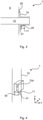
- Fig 2 is a schematic diagram illustrating one embodiment of a striking plate assembly 1.
- the striking plate assembly 1 comprises a striking plate 10 and at least one sensor device 11. In this embodiment, there are two sensor devices 11.
- the striking plate is made of metal and secures the position of a locking bolt 13 when extended from the lock 15 into the surrounding structure 7, thus making it difficult for an attacker to break open the barrier.
- the striking plate assembly 1 is for use with a lock 15 which comprises a locking bolt 13.
- the striking plate 10 comprises a first bolt through-hole 12a through which the locking bolt 13 can pass. When the locking bolt 13 passes through the bolt through-hole 12a, the lock 15 is in a locked state.
- the sensor device 11 of the striking plate assembly 1 is used for detecting a status of the locking bolt 13.
- the status is either that the bolt has been extended through the striking plate or that the bolt is not extended through the striking plate.
- the sensor device 11 is provided attached to the striking plate 10, such that its proximity sensor is vertically displaced, along a longitudinal direction of the striking plate, from the through-hole 12a, 12b through which where the locking bolt 13 is intended to pass.
- the longitudinal direction of the striking plate is along the gap between the barrier and surrounding structure. When the barrier is provided in a sidehung manner, the longitudinal direction is vertical. In other words, in one embodiment, the longitudinal direction is vertically.
- This structure makes the sensor device 11 hidden when the barrier is closed, which reduces a risk of inadvertent damage or external sabotage to the sensor device 11, while maintaining an aesthetic appearance.
- the sensor device can be provided below or above from where the locking bolt 13 is intended to pass.
- the credential antenna is used to communicate with an external credential over a user credential interface 16, described in more detail below.
- the whole striking plate assembly can easily replace a previous striking plate, greatly simplifying retrofitting to provide capability to detect status of the barrier (locked/unlocked).
- a dummy hook forms part of the espagnolette where a corresponding sensor device is provided in the striking plate assembly by the through-hole corresponding to the dummy hook.
- the sensor device can detect when the barrier is closed and bolted.
- the sensing can be achieved by the proximity sensor being an inductive sensor, which is able to detect the presence or absence of a hook comprising metal.
- the proximity sensor can be based on any one or more of electrical capacity, electrical inductivity, infrared light, magnetism (e.g. a hall sensor), photocell, sonar, mechanical switch etc.
- the sensor device 11 can be a selfcontained device comprising the proximity sensor, battery, antenna(s), and control circuitry. Such a sensor device 11 is easy to integrate in the striking plate and can be replaced or upgraded when needed.
- the controller 17 is connected to the sensor device 11.
- the interface between the controller 17 and the sensor device 11 can be implemented using a wireless interface, e.g. using Bluetooth, Bluetooth Low Energy (BLE), any of the IEEE 802.15 standards, Radio Frequency Identification (RFID), any of the IEEE 802.11 standards, wireless USB (Universal Serial Bus), etc.
- BLE Bluetooth Low Energy
- RFID Radio Frequency Identification
- USB Universal Serial Bus
- the interface between the controller 17 and the lock 15, when provided separately, can be implemented over any suitable wired or wireless interface, such as BLE or USB.
- the controller 17 comprises a user credential interface 16 for communicating with a user credential 27.
- the user credential interface 16 can be implemented using any suitable wireless interface, e.g. using Bluetooth, BLE, any of the IEEE 802.15 standards, RFID, Near Field Communication (NFC), any of the IEEE 802. 11 standards, wireless USB, etc.
- the user credential interface 16 can be implemented using wirebased communication, e.g. using USB, Ethernet, serial connection (e.g. RS-485), etc.
- the controller 17 is provided with a way to communicate with a remote control device (not shown), such as a smart phone, computer etc. for remote lock management.
- a remote control device such as a smart phone, computer etc. for remote lock management.
- the controller 17 is remotely controllable, e.g. to allow access for a particular user credential or to remotely unlock the lock (e.g. for a tradesman, cleaner, child who have lost a key, etc.).
- the remote communication enables event monitoring, e.g. of unlocking status, locking status, opening, closing, etc., which can be detected by the sensor device.
- the controller 17 can be hardware based, e.g. using an Application Specific Integrated Circuit (ASIC), a Field Programmable Gate Array (FPGA), and/or discrete components.
- ASIC Application Specific Integrated Circuit
- FPGA Field Programmable Gate Array
- the controller 17 is software based, comprising a processor using any combination of one or more of a suitable central processing unit (CPU), microcontroller, digital signal processor (DSP), etc., capable of executing software instructions stored in a persistent memory accessible to the controller 17.
- CPU central processing unit
- DSP digital signal processor
- the user credential 27 can be implemented using any suitable device portable by a user and which can be used for authentication over the credential interface 16.
- the user credential 27 is typically carried or worn by the user 8 and may be implemented as a mobile phone, a smartphone, a key fob, wearable device, smart phone case, access card, electronic physical key, etc.
- the authenticity of the user credential 27 can be checked by the controller 17 in an access control procedure, e.g. using a challenge and response scheme.
- the authorisation to open the lock 15 is then checked, either by the controller 17 itself, or by communicating with an external (local or remote) authorisation device (not shown) to reach an access decision whether to grant or deny access.
- the controller 17 also receives sensor data from the sensor device 11 indicating the presence or absence of a locking bolt 13. Presence of the locking bolt 13 indicates an extended locking bolt 13, corresponding to a locked state, and absence of the locking bolt 13 indicates a retracted locking bolt 13, corresponding to an unlocked state.
- the controller 17 is configured to selectively control the lock 15 based on sensor data received from the sensor device 11 and user credential data received over the credential interface 16.
- the controller 17 determines whether to retract or extend the locking bolt 13 by sending an appropriate control signal to the lock 15.
- the controller 17 sends a control signal to the lock 15 to retract the locking bolt 13 to thereby alter the state of the lock 15 from locked to unlocked.
- the controller 17 does not send any control signal to the lock 15 to retract the locking bolt 13, since the locking bolt 13 is already retracted, i.e. the lock is already in the unlocked state.
- the controller 17 When the locking bolt is extended and the access decision is to deny access, the controller 17 does not send any control signal to the lock 15 to retract the locking bolt 13 since the state of the lock 15 is already in the correct state, i.e. the locked state.
- the striking plate assembly 1 By providing the sensor device in the striking plate assembly 1 rather than in the lock, a cost effective status control of a lock and door is achieved. For instance, this greatly improves the ease and cost with which an existing lock installation can be upgraded to an electronic lock by a simple retrofit.
- the lock 15 itself can remain as before (or upgraded separately) and only the striking plate assembly is replaced after which the state of locked or unlocked can be determined using the sensor device of the striking plate assembly 11.
- the striking plate assembly can be installed and configured to provide this functionality.
- the striking plate assembly 1 further comprises a second sensor device 11 for detecting a status of a separate latch bolt 14 of the lock 15 to gain better information about the status of the door.
- a second sensor device 11 for detecting a status of a separate latch bolt 14 of the lock 15 to gain better information about the status of the door.
- the latch bolt 14 is present, this indicates that the barrier 5 is closed.
- the latch bolt 14 is absent, this indicates that the barrier is open.
- the presence or absence of the latch bolt 14 in a second bolt through-hole 12b of the striking plate 10 as detected by the second sensor device 11 and transmitted as sensor data to the controller 17, can be interpreted as whether the barrier 5 is open (when the latch bolt 14 is absent) or closed (when the latch bolt 14 is present).
- a user output device 18 can also be provided connected to the controller 17.
- the user output device 18 can be any one or more of a LED (light emitting diode), lamp, beeper, sound device, display, etc.
- the controller 17 is then configured to provide user feedback via the user output device 18.
- the user feedback can be used to indicate any of the following situations: access granted, access denied, access granted but no change (e.g. if the barrier is already open), etc.
- the controller 17 is remotely controllable, the user output can optionally be provided in parallel to a device performing the remote control. For instance, if a user remotely unlocks the door for a tradesman, the successful unlocking can result in a green LED indicating that the door is unlocked to the tradesman, as well as an indicator on the user interface of the remote control device.
- the controller is configured to use the user output device 18 to indicate status of other locks when the user locks the barrier on the outside. For instance, an indication can be shown that all other locks are in a locked state or that at least one lock is in an unlocked state.
- Fig 3 is a schematic side view diagram illustrating an embodiment of sensor placement by the striking plate 10 of Fig 2 .
- the sensor device 11 is provided below and adjacent along the open space where the locking bolt 13 can extend.
- the proximity sensor 20 is directed in towards where the locking bolt can extend.
- the proximity sensor 20 can comprise a proximity antenna. Alternatively or additionally, the same principle can be applied for a latch bolt 14.
- the sensor device 11 is provided such that its credential antenna 21 is directed towards a gap 25 between the striking plate assembly and the physical barrier, when the striking plate assembly 1 is installed, which is on the left side of the sensor device 11 in Fig 3 .
- the credential antenna 21 is made up of multiple antennas, such as an inductive credential antenna for RFID/NFC and an RF (Radio Frequency) credential antenna for BLE, all credential antennas are directed in the same direction, towards the gap 25 between the striking plate assembly and the physical barrier, when the striking plate assembly 1 is installed. In this way, communication to/from the credential antenna 21 can pass through the gap 25 between the physical barrier 5 and the striking plate 10, even when the barrier is closed. This allows communication to occur efficiently, even in situations when one or both of the physical barrier 5 and the surrounding structure is made partly or completely of metal.
- Fig 4 is a schematic perspective view diagram illustrating an embodiment of sensor placement by the striking plate 10 of Fig 2 .
- Fig 4 corresponds to the embodiment illustrated in Fig 3 .
- a first through-hole 30 of the striking plate 10 can be seen.
- the sensor device 11 is provided in the first through-hole 30.
- the first through-hole 30 is provided between the sensor device 11 and the gap between the striking plate assembly and the physical barrier, when the striking plate assembly is installed.
- the sensor device can be provided in the first through-hole 30 such that the sensor device 11 is essentially (+- 3 mm or even +-1 mm) in the same plane as sections of the striking plate around the first through-hole 30. The plane is then the surface towards the gap 25 between the striking plate assembly and the physical barrier, when the striking plate assembly (1) is installed.
- the sensor device 11 is protected from external damage, while any negative effects of the striking plate is reduced for communication to or from the antenna 21.
- a second through-hole 31 is shown.
- the second through-hole 31 is provided between the sensor device 11 and where the locking bolt is intended to pass, i.e. in the space inside the first bolt through-hole 12a.
- the same principle can be applied for a latch bolt.
- Fig 5 is a schematic perspective view diagram illustrating the embodiment of Fig 4 in more detail.
- the proximity sensor 20 of the sensor device 11 faces the space where the locking bolt 13 is intended to pass when extended, i.e. in the space inside the first bolt through-hole 12a.
- the proximity sensor can detect when the locking bolt passes through the first bolt through-hole (i.e. when the locking bolt is locked) and when it does not (i.e. when the locking bolt is unlocked).
- the antenna 21 of the sensor device is directed towards the gap 25 between the striking plate assembly and the physical barrier, when the striking plate assembly 1 is installed.
- the locking bolt is here shown to move in a pure linear movement, the locking bolt can equally well be movable in a rotational movement or a movement being a combination of rotational and linear movement. Alternatively or additionally, the same principle can be applied for a latch bolt.
Landscapes
- Lock And Its Accessories (AREA)
Claims (7)
- Schließblechanordnung (1), die Folgendes umfasst:ein Schließblech (10) undeine Sensorvorrichtung (11) zum Detektieren eines Status eines Bolzens (13, 14) eines Schlosses (15) für eine physische Sperre, wobei die Sensorvorrichtung (11) einen Näherungssensor (20) und eine Antenne (21) umfasst;wobei die Sensorvorrichtung (11) derart bereitgestellt ist, dass ihr Näherungssensor (20) entlang einer Längsrichtung des Schließblechs von einem Durchgangsloch (12a, 12b), durch das der Bolzen (13, 14) verlaufen soll, vertikal versetzt bereitgestellt ist;dadurch gekennzeichnet, dassdie Sensorvorrichtung (11) derart bereitgestellt ist, dass ihre Antenne (21) zwischen der Schließblechanordnung und der physischen Sperre auf einen Spalt (25) gerichtet ist, wenn die Schließblechanordnung (1) installiert ist.
- Schließblechanordnung (1) nach Anspruch 1, wobei der Näherungssensor (20) dem Raum zugewandt ist, durch den der Verriegelungsbolzen (13) verlaufen soll, wenn er eingedreht ist.
- Schließblechanordnung (1) nach Anspruch 1 oder 2, wobei das Schließblech (10) zwischen der Sensorvorrichtung (11) und dem Spalt (25) zwischen der Schließblechanordnung und der physischen Sperre ein erstes Durchgangsloch (30) umfasst, wenn die Schließblechanordnung (1) installiert ist.
- Schließblechanordnung nach Anspruch 3, wobei die Sensorvorrichtung im ersten Durchgangsloch (30) derart bereitgestellt ist, dass sich die Sensorvorrichtung (11) im Wesentlichen auf derselben Ebene befindet wie Abschnitte des Schließblechs um das erste Durchgangsloch (30), wobei die Ebene die Fläche zum Spalt (25) zwischen der Schließblechanordnung und der physischen Sperre ist, wenn die Schließblechanordnung (1) installiert ist.
- Schließblechanordnung (1) nach einem der vorhergehenden Ansprüche, wobei das Schließblech (10) zwischen der Sensorvorrichtung und der Stelle, durch die der Bolzen verlaufen soll, ein zweites Durchgangsloch (31) umfasst.
- Schließblechanordnung (1) nach einem der vorhergehenden Ansprüche, wobei der Näherungssensor (20) ein induktiver Sensor ist.
- Schließblechanordnung (1) nach einem der vorhergehenden Ansprüche, wobei die Sensorvorrichtung (11) am Schließblech (10) befestigt ist.
Applications Claiming Priority (2)
| Application Number | Priority Date | Filing Date | Title |
|---|---|---|---|
| EP18152780 | 2018-01-22 | ||
| PCT/EP2018/085626 WO2019141470A1 (en) | 2018-01-22 | 2018-12-18 | Striking plate assembly |
Publications (2)
| Publication Number | Publication Date |
|---|---|
| EP3743577A1 EP3743577A1 (de) | 2020-12-02 |
| EP3743577B1 true EP3743577B1 (de) | 2022-02-23 |
Family
ID=61017856
Family Applications (1)
| Application Number | Title | Priority Date | Filing Date |
|---|---|---|---|
| EP18819131.6A Active EP3743577B1 (de) | 2018-01-22 | 2018-12-18 | Schliessblechanordnung |
Country Status (5)
| Country | Link |
|---|---|
| US (1) | US20200362592A1 (de) |
| EP (1) | EP3743577B1 (de) |
| KR (1) | KR102547132B1 (de) |
| CN (1) | CN111630236A (de) |
| WO (1) | WO2019141470A1 (de) |
Families Citing this family (1)
| Publication number | Priority date | Publication date | Assignee | Title |
|---|---|---|---|---|
| US11639617B1 (en) | 2019-04-03 | 2023-05-02 | The Chamberlain Group Llc | Access control system and method |
Citations (2)
| Publication number | Priority date | Publication date | Assignee | Title |
|---|---|---|---|---|
| DE10059582C2 (de) * | 2000-11-30 | 2003-04-30 | Roto Frank Ag | Überwachungseinrichtung für ein Fenster, eine Tür oder dergleichen |
| WO2006015404A1 (en) * | 2004-08-13 | 2006-02-16 | Trevor David Leisk | Micro-switch boxes for locking arrangements |
Family Cites Families (27)
| Publication number | Priority date | Publication date | Assignee | Title |
|---|---|---|---|---|
| US3803575A (en) * | 1971-02-15 | 1974-04-09 | M Gotanda | Device for setting-up a power source of electrical alarm |
| FR2698656B1 (fr) * | 1992-12-02 | 1995-01-20 | Jacques Lewiner | Perfectionnements aux dispositifs pour détecter la position engagée d'un pêne. |
| US6078256A (en) * | 1994-08-24 | 2000-06-20 | Designtech International, Inc. | Dead-bolt lock monitoring unit and system |
| DE4445730A1 (de) * | 1994-12-21 | 1996-07-18 | Grundig Emv | Vorrichtung zum Scharfschalten einer Alarmanlage und zur Überwachung einer Eingangstür |
| DE19500054C1 (de) * | 1995-01-03 | 1996-07-18 | Rgw Rechtsrheinische Gas Und W | Einrichtung zum Überwachen des Schließzustandes einer Tür oder dergleichen |
| US5925861A (en) * | 1997-04-02 | 1999-07-20 | Sidney Fromberg | Security door lock arrangement with magnetically operated switch in the closed door position |
| US6359538B1 (en) * | 2000-09-12 | 2002-03-19 | Daniel M. Jolley | Bracket assembly for mounting a reed switch and associated magnet |
| US7151449B2 (en) * | 2002-08-06 | 2006-12-19 | Major Monitors | Automatic lockset tamper detection device and method |
| KR200300365Y1 (ko) * | 2002-10-21 | 2003-01-14 | (주)아거스 | 개폐감지용 도어록시스템 |
| KR200384248Y1 (ko) * | 2005-02-17 | 2005-05-12 | 주식회사 아이레보 | 문 처짐 감지 장치 |
| JP4623058B2 (ja) * | 2007-06-26 | 2011-02-02 | 村田機械株式会社 | ドアスイッチシステム |
| NZ599424A (en) * | 2009-10-06 | 2013-05-31 | Assa Abloy Australia Pty Ltd | Improved electric strike and combination with improved lock assembly |
| US8466786B2 (en) * | 2010-08-16 | 2013-06-18 | Rav-Mafteah Ltd. | Locking mechanism with sabbath control unit |
| DE202011103840U1 (de) * | 2011-07-29 | 2011-11-30 | Carl Fuhr Gmbh & Co. Kg | Schließanlage mit Mehrfachverriegelung für eine Tür |
| DE102011110776B4 (de) * | 2011-08-22 | 2013-09-05 | Hoppe Holding Ag | Überwachungsvorrichtung zur Positionsbestimmung eines Schlossriegels |
| GB2505003A (en) | 2012-08-18 | 2014-02-19 | Mark Gray | Fenestration alarm contact sensor for determining a locked and unlocked configuration |
| AU2013202619B2 (en) * | 2013-02-20 | 2017-06-22 | D & D Group Pty Ltd | Sensor Configuration for a Latching Assembly |
| FI125651B (fi) * | 2013-06-11 | 2015-12-31 | Rollock Oy | Oven lukko ja järjestely tehon ja informaation siirtämiseksi oven lukkoon |
| WO2015171387A1 (en) * | 2014-05-07 | 2015-11-12 | Thomson Licensing | A self-contained deadbolt sensing arrangement |
| US20160017640A1 (en) * | 2014-07-15 | 2016-01-21 | Alarm Lock Systems, Inc. | Electronic Door Locking System |
| GB2528468A (en) * | 2014-07-22 | 2016-01-27 | Mighton Products Ltd | Window status sensor system |
| US20170362856A1 (en) * | 2016-06-16 | 2017-12-21 | Spectrum Brands, Inc. | Strike plate with bolt sensing feature |
| DE102016125888A1 (de) * | 2016-12-29 | 2018-07-05 | SCHÜCO International KG | Rahmen-Überwachungsvorrichtung für Fenster oder Türen und Fenster oder Tür mit Rahmen-Überwachungsvorrichtung |
| CN206681510U (zh) * | 2017-04-18 | 2017-11-28 | 冷晋川 | 智能双电机电子锁 |
| TWM552948U (zh) * | 2017-09-04 | 2017-12-11 | Vision Automobile Electronics Industrial Co Ltd | 感測模組 |
| US11308742B2 (en) * | 2018-01-22 | 2022-04-19 | Assa Abloy Ab | Electronic lock with slot antenna |
| FR3096386B1 (fr) * | 2019-05-23 | 2021-08-20 | Cetih | dispositif de capteur d’état d’un organe de verrouillage ou de condamnation pour menuiserie |
-
2018
- 2018-12-18 EP EP18819131.6A patent/EP3743577B1/de active Active
- 2018-12-18 WO PCT/EP2018/085626 patent/WO2019141470A1/en active Search and Examination
- 2018-12-18 CN CN201880087049.1A patent/CN111630236A/zh active Pending
- 2018-12-18 US US16/961,888 patent/US20200362592A1/en active Pending
- 2018-12-18 KR KR1020207021279A patent/KR102547132B1/ko active IP Right Grant
Patent Citations (2)
| Publication number | Priority date | Publication date | Assignee | Title |
|---|---|---|---|---|
| DE10059582C2 (de) * | 2000-11-30 | 2003-04-30 | Roto Frank Ag | Überwachungseinrichtung für ein Fenster, eine Tür oder dergleichen |
| WO2006015404A1 (en) * | 2004-08-13 | 2006-02-16 | Trevor David Leisk | Micro-switch boxes for locking arrangements |
Also Published As
| Publication number | Publication date |
|---|---|
| EP3743577A1 (de) | 2020-12-02 |
| KR102547132B1 (ko) | 2023-06-23 |
| WO2019141470A1 (en) | 2019-07-25 |
| US20200362592A1 (en) | 2020-11-19 |
| KR20200108855A (ko) | 2020-09-21 |
| CN111630236A (zh) | 2020-09-04 |
Similar Documents
| Publication | Publication Date | Title |
|---|---|---|
| KR102580113B1 (ko) | 장벽과 관련하여 휴대용 열쇠장치가 활성영역에 있는지 여부를 결정하는 방법, 장치, 컴퓨터 프로그램 및 컴퓨터 프로그램 제품 | |
| US9702165B2 (en) | Sensor system for a locking system and method for detecting tamperings at a locking system | |
| CN109312576B (zh) | 具有整合的到达角度(aoa)检测的无线锁具 | |
| EP3094797B1 (de) | Schlüsselkasten | |
| CA2626960A1 (en) | Door entry security device with electronic lock | |
| EP3743958B1 (de) | Elektronisches schloss mit schlitzantenne | |
| EP3987134B1 (de) | Magnet in bolzen | |
| EP3743577B1 (de) | Schliessblechanordnung | |
| EP3987133B1 (de) | Bolzenidentität | |
| US20180301004A1 (en) | Security device for integration into a security system | |
| JP2007239224A (ja) | 建物のセキュリティシステム | |
| CN114008282B (zh) | 栓身份 | |
| JP6125816B2 (ja) | 電気錠システム | |
| KR101953538B1 (ko) | 스마트 도어록 및 그 제어방법 | |
| JP2005307471A (ja) | 入退室管理装置および入退室管理方法 | |
| JP2015014128A (ja) | 警備信号出力装置 | |
| CN106780888A (zh) | 一种基于压力传感器的卧室门禁装置 |
Legal Events
| Date | Code | Title | Description |
|---|---|---|---|
| STAA | Information on the status of an ep patent application or granted ep patent |
Free format text: STATUS: UNKNOWN |
|
| STAA | Information on the status of an ep patent application or granted ep patent |
Free format text: STATUS: THE INTERNATIONAL PUBLICATION HAS BEEN MADE |
|
| PUAI | Public reference made under article 153(3) epc to a published international application that has entered the european phase |
Free format text: ORIGINAL CODE: 0009012 |
|
| STAA | Information on the status of an ep patent application or granted ep patent |
Free format text: STATUS: REQUEST FOR EXAMINATION WAS MADE |
|
| 17P | Request for examination filed |
Effective date: 20200707 |
|
| AK | Designated contracting states |
Kind code of ref document: A1 Designated state(s): AL AT BE BG CH CY CZ DE DK EE ES FI FR GB GR HR HU IE IS IT LI LT LU LV MC MK MT NL NO PL PT RO RS SE SI SK SM TR |
|
| AX | Request for extension of the european patent |
Extension state: BA ME |
|
| DAV | Request for validation of the european patent (deleted) | ||
| DAX | Request for extension of the european patent (deleted) | ||
| GRAP | Despatch of communication of intention to grant a patent |
Free format text: ORIGINAL CODE: EPIDOSNIGR1 |
|
| STAA | Information on the status of an ep patent application or granted ep patent |
Free format text: STATUS: GRANT OF PATENT IS INTENDED |
|
| INTG | Intention to grant announced |
Effective date: 20211008 |
|
| GRAS | Grant fee paid |
Free format text: ORIGINAL CODE: EPIDOSNIGR3 |
|
| GRAA | (expected) grant |
Free format text: ORIGINAL CODE: 0009210 |
|
| STAA | Information on the status of an ep patent application or granted ep patent |
Free format text: STATUS: THE PATENT HAS BEEN GRANTED |
|
| AK | Designated contracting states |
Kind code of ref document: B1 Designated state(s): AL AT BE BG CH CY CZ DE DK EE ES FI FR GB GR HR HU IE IS IT LI LT LU LV MC MK MT NL NO PL PT RO RS SE SI SK SM TR |
|
| REG | Reference to a national code |
Ref country code: GB Ref legal event code: FG4D |
|
| RIN1 | Information on inventor provided before grant (corrected) |
Inventor name: VON MATERN, JOHAN Inventor name: CEDERBLAD, MATS Inventor name: JONSSON, TOMAS |
|
| REG | Reference to a national code |
Ref country code: CH Ref legal event code: EP |
|
| REG | Reference to a national code |
Ref country code: DE Ref legal event code: R096 Ref document number: 602018031350 Country of ref document: DE |
|
| REG | Reference to a national code |
Ref country code: AT Ref legal event code: REF Ref document number: 1470589 Country of ref document: AT Kind code of ref document: T Effective date: 20220315 |
|
| REG | Reference to a national code |
Ref country code: IE Ref legal event code: FG4D |
|
| REG | Reference to a national code |
Ref country code: LT Ref legal event code: MG9D |
|
| REG | Reference to a national code |
Ref country code: SE Ref legal event code: TRGR |
|
| REG | Reference to a national code |
Ref country code: NL Ref legal event code: MP Effective date: 20220223 |
|
| REG | Reference to a national code |
Ref country code: AT Ref legal event code: MK05 Ref document number: 1470589 Country of ref document: AT Kind code of ref document: T Effective date: 20220223 |
|
| PG25 | Lapsed in a contracting state [announced via postgrant information from national office to epo] |
Ref country code: RS Free format text: LAPSE BECAUSE OF FAILURE TO SUBMIT A TRANSLATION OF THE DESCRIPTION OR TO PAY THE FEE WITHIN THE PRESCRIBED TIME-LIMIT Effective date: 20220223 Ref country code: PT Free format text: LAPSE BECAUSE OF FAILURE TO SUBMIT A TRANSLATION OF THE DESCRIPTION OR TO PAY THE FEE WITHIN THE PRESCRIBED TIME-LIMIT Effective date: 20220623 Ref country code: NO Free format text: LAPSE BECAUSE OF FAILURE TO SUBMIT A TRANSLATION OF THE DESCRIPTION OR TO PAY THE FEE WITHIN THE PRESCRIBED TIME-LIMIT Effective date: 20220523 Ref country code: NL Free format text: LAPSE BECAUSE OF FAILURE TO SUBMIT A TRANSLATION OF THE DESCRIPTION OR TO PAY THE FEE WITHIN THE PRESCRIBED TIME-LIMIT Effective date: 20220223 Ref country code: LT Free format text: LAPSE BECAUSE OF FAILURE TO SUBMIT A TRANSLATION OF THE DESCRIPTION OR TO PAY THE FEE WITHIN THE PRESCRIBED TIME-LIMIT Effective date: 20220223 Ref country code: HR Free format text: LAPSE BECAUSE OF FAILURE TO SUBMIT A TRANSLATION OF THE DESCRIPTION OR TO PAY THE FEE WITHIN THE PRESCRIBED TIME-LIMIT Effective date: 20220223 Ref country code: ES Free format text: LAPSE BECAUSE OF FAILURE TO SUBMIT A TRANSLATION OF THE DESCRIPTION OR TO PAY THE FEE WITHIN THE PRESCRIBED TIME-LIMIT Effective date: 20220223 Ref country code: BG Free format text: LAPSE BECAUSE OF FAILURE TO SUBMIT A TRANSLATION OF THE DESCRIPTION OR TO PAY THE FEE WITHIN THE PRESCRIBED TIME-LIMIT Effective date: 20220523 |
|
| PG25 | Lapsed in a contracting state [announced via postgrant information from national office to epo] |
Ref country code: PL Free format text: LAPSE BECAUSE OF FAILURE TO SUBMIT A TRANSLATION OF THE DESCRIPTION OR TO PAY THE FEE WITHIN THE PRESCRIBED TIME-LIMIT Effective date: 20220223 Ref country code: LV Free format text: LAPSE BECAUSE OF FAILURE TO SUBMIT A TRANSLATION OF THE DESCRIPTION OR TO PAY THE FEE WITHIN THE PRESCRIBED TIME-LIMIT Effective date: 20220223 Ref country code: GR Free format text: LAPSE BECAUSE OF FAILURE TO SUBMIT A TRANSLATION OF THE DESCRIPTION OR TO PAY THE FEE WITHIN THE PRESCRIBED TIME-LIMIT Effective date: 20220524 Ref country code: FI Free format text: LAPSE BECAUSE OF FAILURE TO SUBMIT A TRANSLATION OF THE DESCRIPTION OR TO PAY THE FEE WITHIN THE PRESCRIBED TIME-LIMIT Effective date: 20220223 Ref country code: AT Free format text: LAPSE BECAUSE OF FAILURE TO SUBMIT A TRANSLATION OF THE DESCRIPTION OR TO PAY THE FEE WITHIN THE PRESCRIBED TIME-LIMIT Effective date: 20220223 |
|
| PG25 | Lapsed in a contracting state [announced via postgrant information from national office to epo] |
Ref country code: IS Free format text: LAPSE BECAUSE OF FAILURE TO SUBMIT A TRANSLATION OF THE DESCRIPTION OR TO PAY THE FEE WITHIN THE PRESCRIBED TIME-LIMIT Effective date: 20220623 |
|
| PG25 | Lapsed in a contracting state [announced via postgrant information from national office to epo] |
Ref country code: SM Free format text: LAPSE BECAUSE OF FAILURE TO SUBMIT A TRANSLATION OF THE DESCRIPTION OR TO PAY THE FEE WITHIN THE PRESCRIBED TIME-LIMIT Effective date: 20220223 Ref country code: SK Free format text: LAPSE BECAUSE OF FAILURE TO SUBMIT A TRANSLATION OF THE DESCRIPTION OR TO PAY THE FEE WITHIN THE PRESCRIBED TIME-LIMIT Effective date: 20220223 Ref country code: RO Free format text: LAPSE BECAUSE OF FAILURE TO SUBMIT A TRANSLATION OF THE DESCRIPTION OR TO PAY THE FEE WITHIN THE PRESCRIBED TIME-LIMIT Effective date: 20220223 Ref country code: EE Free format text: LAPSE BECAUSE OF FAILURE TO SUBMIT A TRANSLATION OF THE DESCRIPTION OR TO PAY THE FEE WITHIN THE PRESCRIBED TIME-LIMIT Effective date: 20220223 Ref country code: DK Free format text: LAPSE BECAUSE OF FAILURE TO SUBMIT A TRANSLATION OF THE DESCRIPTION OR TO PAY THE FEE WITHIN THE PRESCRIBED TIME-LIMIT Effective date: 20220223 Ref country code: CZ Free format text: LAPSE BECAUSE OF FAILURE TO SUBMIT A TRANSLATION OF THE DESCRIPTION OR TO PAY THE FEE WITHIN THE PRESCRIBED TIME-LIMIT Effective date: 20220223 |
|
| REG | Reference to a national code |
Ref country code: DE Ref legal event code: R097 Ref document number: 602018031350 Country of ref document: DE |
|
| PG25 | Lapsed in a contracting state [announced via postgrant information from national office to epo] |
Ref country code: AL Free format text: LAPSE BECAUSE OF FAILURE TO SUBMIT A TRANSLATION OF THE DESCRIPTION OR TO PAY THE FEE WITHIN THE PRESCRIBED TIME-LIMIT Effective date: 20220223 |
|
| PLBE | No opposition filed within time limit |
Free format text: ORIGINAL CODE: 0009261 |
|
| STAA | Information on the status of an ep patent application or granted ep patent |
Free format text: STATUS: NO OPPOSITION FILED WITHIN TIME LIMIT |
|
| 26N | No opposition filed |
Effective date: 20221124 |
|
| PG25 | Lapsed in a contracting state [announced via postgrant information from national office to epo] |
Ref country code: SI Free format text: LAPSE BECAUSE OF FAILURE TO SUBMIT A TRANSLATION OF THE DESCRIPTION OR TO PAY THE FEE WITHIN THE PRESCRIBED TIME-LIMIT Effective date: 20220223 |
|
| P01 | Opt-out of the competence of the unified patent court (upc) registered |
Effective date: 20230530 |
|
| PG25 | Lapsed in a contracting state [announced via postgrant information from national office to epo] |
Ref country code: IT Free format text: LAPSE BECAUSE OF FAILURE TO SUBMIT A TRANSLATION OF THE DESCRIPTION OR TO PAY THE FEE WITHIN THE PRESCRIBED TIME-LIMIT Effective date: 20220223 |
|
| REG | Reference to a national code |
Ref country code: CH Ref legal event code: PL |
|
| REG | Reference to a national code |
Ref country code: BE Ref legal event code: MM Effective date: 20221231 |
|
| PG25 | Lapsed in a contracting state [announced via postgrant information from national office to epo] |
Ref country code: LU Free format text: LAPSE BECAUSE OF NON-PAYMENT OF DUE FEES Effective date: 20221218 |
|
| PG25 | Lapsed in a contracting state [announced via postgrant information from national office to epo] |
Ref country code: LI Free format text: LAPSE BECAUSE OF NON-PAYMENT OF DUE FEES Effective date: 20221231 Ref country code: CH Free format text: LAPSE BECAUSE OF NON-PAYMENT OF DUE FEES Effective date: 20221231 |
|
| PG25 | Lapsed in a contracting state [announced via postgrant information from national office to epo] |
Ref country code: BE Free format text: LAPSE BECAUSE OF NON-PAYMENT OF DUE FEES Effective date: 20221231 |
|
| PGFP | Annual fee paid to national office [announced via postgrant information from national office to epo] |
Ref country code: GB Payment date: 20231109 Year of fee payment: 6 |
|
| PGFP | Annual fee paid to national office [announced via postgrant information from national office to epo] |
Ref country code: SE Payment date: 20231110 Year of fee payment: 6 Ref country code: IE Payment date: 20231109 Year of fee payment: 6 Ref country code: FR Payment date: 20231122 Year of fee payment: 6 Ref country code: DE Payment date: 20231107 Year of fee payment: 6 |
|
| PG25 | Lapsed in a contracting state [announced via postgrant information from national office to epo] |
Ref country code: CY Free format text: LAPSE BECAUSE OF FAILURE TO SUBMIT A TRANSLATION OF THE DESCRIPTION OR TO PAY THE FEE WITHIN THE PRESCRIBED TIME-LIMIT Effective date: 20220223 |