EP3742883B1 - System und verfahren zum autonomen ernten von pilzen - Google Patents
System und verfahren zum autonomen ernten von pilzen Download PDFInfo
- Publication number
- EP3742883B1 EP3742883B1 EP19885549.6A EP19885549A EP3742883B1 EP 3742883 B1 EP3742883 B1 EP 3742883B1 EP 19885549 A EP19885549 A EP 19885549A EP 3742883 B1 EP3742883 B1 EP 3742883B1
- Authority
- EP
- European Patent Office
- Prior art keywords
- picking
- mushroom
- mushrooms
- harvester
- bed
- Prior art date
- Legal status (The legal status is an assumption and is not a legal conclusion. Google has not performed a legal analysis and makes no representation as to the accuracy of the status listed.)
- Active
Links
- 235000001674 Agaricus brunnescens Nutrition 0.000 title claims description 293
- 238000003306 harvesting Methods 0.000 title claims description 54
- 238000000034 method Methods 0.000 title claims description 43
- 230000033001 locomotion Effects 0.000 claims description 29
- 238000012545 processing Methods 0.000 claims description 23
- 230000008569 process Effects 0.000 claims description 17
- 238000013519 translation Methods 0.000 claims description 13
- 230000004044 response Effects 0.000 claims description 6
- 210000003811 finger Anatomy 0.000 description 70
- 230000007246 mechanism Effects 0.000 description 24
- 239000000758 substrate Substances 0.000 description 22
- 238000007667 floating Methods 0.000 description 9
- 238000003860 storage Methods 0.000 description 9
- 238000013459 approach Methods 0.000 description 8
- 238000001514 detection method Methods 0.000 description 7
- 238000005516 engineering process Methods 0.000 description 7
- 230000003287 optical effect Effects 0.000 description 7
- 230000009471 action Effects 0.000 description 5
- 239000002361 compost Substances 0.000 description 4
- 238000010276 construction Methods 0.000 description 4
- 230000007613 environmental effect Effects 0.000 description 4
- 238000002955 isolation Methods 0.000 description 4
- 239000002689 soil Substances 0.000 description 4
- 208000034656 Contusions Diseases 0.000 description 3
- 241001124569 Lycaenidae Species 0.000 description 3
- 230000033228 biological regulation Effects 0.000 description 3
- 238000001816 cooling Methods 0.000 description 3
- 201000010099 disease Diseases 0.000 description 3
- 208000037265 diseases, disorders, signs and symptoms Diseases 0.000 description 3
- 239000000284 extract Substances 0.000 description 3
- 238000003973 irrigation Methods 0.000 description 3
- 230000002262 irrigation Effects 0.000 description 3
- 239000000463 material Substances 0.000 description 3
- 238000005259 measurement Methods 0.000 description 3
- 241000222519 Agaricus bisporus Species 0.000 description 2
- 229910000831 Steel Inorganic materials 0.000 description 2
- 229910052782 aluminium Inorganic materials 0.000 description 2
- XAGFODPZIPBFFR-UHFFFAOYSA-N aluminium Chemical compound [Al] XAGFODPZIPBFFR-UHFFFAOYSA-N 0.000 description 2
- 230000000712 assembly Effects 0.000 description 2
- 238000000429 assembly Methods 0.000 description 2
- 230000015572 biosynthetic process Effects 0.000 description 2
- 238000004891 communication Methods 0.000 description 2
- 238000010586 diagram Methods 0.000 description 2
- 238000005755 formation reaction Methods 0.000 description 2
- 230000006870 function Effects 0.000 description 2
- 238000003780 insertion Methods 0.000 description 2
- 230000037431 insertion Effects 0.000 description 2
- 238000012986 modification Methods 0.000 description 2
- 230000004048 modification Effects 0.000 description 2
- 238000005457 optimization Methods 0.000 description 2
- 238000004806 packaging method and process Methods 0.000 description 2
- 229920000642 polymer Polymers 0.000 description 2
- 238000002360 preparation method Methods 0.000 description 2
- 239000010959 steel Substances 0.000 description 2
- 210000003813 thumb Anatomy 0.000 description 2
- 238000012546 transfer Methods 0.000 description 2
- XLYOFNOQVPJJNP-UHFFFAOYSA-N water Substances O XLYOFNOQVPJJNP-UHFFFAOYSA-N 0.000 description 2
- 241000282412 Homo Species 0.000 description 1
- 244000103635 Lyophyllum ulmarium Species 0.000 description 1
- 241000607479 Yersinia pestis Species 0.000 description 1
- 230000002411 adverse Effects 0.000 description 1
- 238000005273 aeration Methods 0.000 description 1
- 238000004458 analytical method Methods 0.000 description 1
- 230000004888 barrier function Effects 0.000 description 1
- 230000006399 behavior Effects 0.000 description 1
- 238000005452 bending Methods 0.000 description 1
- 230000005540 biological transmission Effects 0.000 description 1
- 230000003749 cleanliness Effects 0.000 description 1
- 239000002131 composite material Substances 0.000 description 1
- 238000005520 cutting process Methods 0.000 description 1
- 238000013480 data collection Methods 0.000 description 1
- 238000013500 data storage Methods 0.000 description 1
- 238000013461 design Methods 0.000 description 1
- 238000011161 development Methods 0.000 description 1
- 230000000694 effects Effects 0.000 description 1
- 238000000605 extraction Methods 0.000 description 1
- 238000001914 filtration Methods 0.000 description 1
- 230000002070 germicidal effect Effects 0.000 description 1
- 230000009931 harmful effect Effects 0.000 description 1
- 238000003384 imaging method Methods 0.000 description 1
- 238000011065 in-situ storage Methods 0.000 description 1
- 238000009776 industrial production Methods 0.000 description 1
- 208000015181 infectious disease Diseases 0.000 description 1
- 239000004615 ingredient Substances 0.000 description 1
- 230000003993 interaction Effects 0.000 description 1
- 230000002452 interceptive effect Effects 0.000 description 1
- 239000000314 lubricant Substances 0.000 description 1
- 238000012423 maintenance Methods 0.000 description 1
- 230000014759 maintenance of location Effects 0.000 description 1
- 238000004519 manufacturing process Methods 0.000 description 1
- 238000013178 mathematical model Methods 0.000 description 1
- 229910052751 metal Inorganic materials 0.000 description 1
- 239000002184 metal Substances 0.000 description 1
- 239000000203 mixture Substances 0.000 description 1
- 238000012544 monitoring process Methods 0.000 description 1
- 230000007935 neutral effect Effects 0.000 description 1
- 235000015097 nutrients Nutrition 0.000 description 1
- 235000008935 nutritious Nutrition 0.000 description 1
- 230000009467 reduction Effects 0.000 description 1
- 230000002787 reinforcement Effects 0.000 description 1
- 230000007480 spreading Effects 0.000 description 1
- 238000003892 spreading Methods 0.000 description 1
- 229910001220 stainless steel Inorganic materials 0.000 description 1
- 239000010935 stainless steel Substances 0.000 description 1
- 238000012549 training Methods 0.000 description 1
- 239000002699 waste material Substances 0.000 description 1
Images


Classifications
-
- A—HUMAN NECESSITIES
- A01—AGRICULTURE; FORESTRY; ANIMAL HUSBANDRY; HUNTING; TRAPPING; FISHING
- A01G—HORTICULTURE; CULTIVATION OF VEGETABLES, FLOWERS, RICE, FRUIT, VINES, HOPS OR SEAWEED; FORESTRY; WATERING
- A01G18/00—Cultivation of mushrooms
- A01G18/60—Cultivation rooms; Equipment therefor
- A01G18/62—Racks; Trays
-
- A—HUMAN NECESSITIES
- A01—AGRICULTURE; FORESTRY; ANIMAL HUSBANDRY; HUNTING; TRAPPING; FISHING
- A01D—HARVESTING; MOWING
- A01D45/00—Harvesting of standing crops
-
- A—HUMAN NECESSITIES
- A01—AGRICULTURE; FORESTRY; ANIMAL HUSBANDRY; HUNTING; TRAPPING; FISHING
- A01D—HARVESTING; MOWING
- A01D46/00—Picking of fruits, vegetables, hops, or the like; Devices for shaking trees or shrubs
- A01D46/30—Robotic devices for individually picking crops
-
- A—HUMAN NECESSITIES
- A01—AGRICULTURE; FORESTRY; ANIMAL HUSBANDRY; HUNTING; TRAPPING; FISHING
- A01G—HORTICULTURE; CULTIVATION OF VEGETABLES, FLOWERS, RICE, FRUIT, VINES, HOPS OR SEAWEED; FORESTRY; WATERING
- A01G18/00—Cultivation of mushrooms
- A01G18/60—Cultivation rooms; Equipment therefor
-
- A—HUMAN NECESSITIES
- A01—AGRICULTURE; FORESTRY; ANIMAL HUSBANDRY; HUNTING; TRAPPING; FISHING
- A01G—HORTICULTURE; CULTIVATION OF VEGETABLES, FLOWERS, RICE, FRUIT, VINES, HOPS OR SEAWEED; FORESTRY; WATERING
- A01G18/00—Cultivation of mushrooms
- A01G18/70—Harvesting
-
- B—PERFORMING OPERATIONS; TRANSPORTING
- B25—HAND TOOLS; PORTABLE POWER-DRIVEN TOOLS; MANIPULATORS
- B25J—MANIPULATORS; CHAMBERS PROVIDED WITH MANIPULATION DEVICES
- B25J15/00—Gripping heads and other end effectors
- B25J15/02—Gripping heads and other end effectors servo-actuated
- B25J15/0206—Gripping heads and other end effectors servo-actuated comprising articulated grippers
- B25J15/022—Gripping heads and other end effectors servo-actuated comprising articulated grippers actuated by articulated links
-
- B—PERFORMING OPERATIONS; TRANSPORTING
- B25—HAND TOOLS; PORTABLE POWER-DRIVEN TOOLS; MANIPULATORS
- B25J—MANIPULATORS; CHAMBERS PROVIDED WITH MANIPULATION DEVICES
- B25J15/00—Gripping heads and other end effectors
- B25J15/02—Gripping heads and other end effectors servo-actuated
- B25J15/0206—Gripping heads and other end effectors servo-actuated comprising articulated grippers
- B25J15/024—Gripping heads and other end effectors servo-actuated comprising articulated grippers having fingers directly connected to actuator
-
- B—PERFORMING OPERATIONS; TRANSPORTING
- B25—HAND TOOLS; PORTABLE POWER-DRIVEN TOOLS; MANIPULATORS
- B25J—MANIPULATORS; CHAMBERS PROVIDED WITH MANIPULATION DEVICES
- B25J15/00—Gripping heads and other end effectors
- B25J15/04—Gripping heads and other end effectors with provision for the remote detachment or exchange of the head or parts thereof
- B25J15/0475—Exchangeable fingers
-
- B—PERFORMING OPERATIONS; TRANSPORTING
- B25—HAND TOOLS; PORTABLE POWER-DRIVEN TOOLS; MANIPULATORS
- B25J—MANIPULATORS; CHAMBERS PROVIDED WITH MANIPULATION DEVICES
- B25J19/00—Accessories fitted to manipulators, e.g. for monitoring, for viewing; Safety devices combined with or specially adapted for use in connection with manipulators
- B25J19/02—Sensing devices
- B25J19/021—Optical sensing devices
- B25J19/022—Optical sensing devices using lasers
-
- B—PERFORMING OPERATIONS; TRANSPORTING
- B25—HAND TOOLS; PORTABLE POWER-DRIVEN TOOLS; MANIPULATORS
- B25J—MANIPULATORS; CHAMBERS PROVIDED WITH MANIPULATION DEVICES
- B25J9/00—Programme-controlled manipulators
- B25J9/02—Programme-controlled manipulators characterised by movement of the arms, e.g. cartesian coordinate type
- B25J9/023—Cartesian coordinate type
- B25J9/026—Gantry-type
-
- B—PERFORMING OPERATIONS; TRANSPORTING
- B25—HAND TOOLS; PORTABLE POWER-DRIVEN TOOLS; MANIPULATORS
- B25J—MANIPULATORS; CHAMBERS PROVIDED WITH MANIPULATION DEVICES
- B25J9/00—Programme-controlled manipulators
- B25J9/02—Programme-controlled manipulators characterised by movement of the arms, e.g. cartesian coordinate type
- B25J9/04—Programme-controlled manipulators characterised by movement of the arms, e.g. cartesian coordinate type by rotating at least one arm, excluding the head movement itself, e.g. cylindrical coordinate type or polar coordinate type
-
- B—PERFORMING OPERATIONS; TRANSPORTING
- B25—HAND TOOLS; PORTABLE POWER-DRIVEN TOOLS; MANIPULATORS
- B25J—MANIPULATORS; CHAMBERS PROVIDED WITH MANIPULATION DEVICES
- B25J9/00—Programme-controlled manipulators
- B25J9/16—Programme controls
- B25J9/1694—Programme controls characterised by use of sensors other than normal servo-feedback from position, speed or acceleration sensors, perception control, multi-sensor controlled systems, sensor fusion
- B25J9/1697—Vision controlled systems
-
- G—PHYSICS
- G06—COMPUTING; CALCULATING OR COUNTING
- G06V—IMAGE OR VIDEO RECOGNITION OR UNDERSTANDING
- G06V20/00—Scenes; Scene-specific elements
- G06V20/10—Terrestrial scenes
- G06V20/188—Vegetation
-
- G—PHYSICS
- G06—COMPUTING; CALCULATING OR COUNTING
- G06V—IMAGE OR VIDEO RECOGNITION OR UNDERSTANDING
- G06V20/00—Scenes; Scene-specific elements
- G06V20/60—Type of objects
- G06V20/68—Food, e.g. fruit or vegetables
-
- G—PHYSICS
- G06—COMPUTING; CALCULATING OR COUNTING
- G06V—IMAGE OR VIDEO RECOGNITION OR UNDERSTANDING
- G06V2201/00—Indexing scheme relating to image or video recognition or understanding
- G06V2201/06—Recognition of objects for industrial automation
Definitions
- the following relates to systems, methods, and apparatus for autonomous harvesting of mushrooms.
- the cultivation of Agaricus bisporus is an intricate process that requires careful preparation of a substrate in multiple stages and the maintenance of precise environmental conditions during the growth and fruiting.
- the substrate (i.e. growing medium) used for cultivation is nutritious compost prepared in a special manner with a layer of casing at the top.
- the casing material should not have any nutrients and should possess good water holding capacity with a texture permitting good aeration and neutral pH level, which causes complex surface and large variation of its height.
- the casing soil needs to be layered on top of the compost infiltrated with mycelia. Harvesting is to be performed after every flush of growth, approximately every 7 to 10 days.
- Agaricus bisporus is usually grown in multilayer shelving growing bed system for efficient utilization of a farm space and for maximizing yields. This infrastructure allows reaching mushrooms on the whole surface from the sides of the bed by human pickers.
- the Dutch-type shelving was not designed to accommodate machinery within its boundaries.
- the beds used for growing mushrooms in the North American region i.e., in approx. 90% of farms) are more or less standard. Usually, there are only about 16 centimeters of space between mushroom caps and the ceiling of the shelves that can be used for any picking apparatus should one be contemplated.
- the standard grow bed system is suitable for manual harvesting, as previously stated, such systems leave little room for the introduction of automated methods of mushroom harvesting without modifying the infrastructure of the farm or the process of cultivation.
- the limited vertical space between the stacked grow beds does not allow for the use of standard harvesting systems due to their large size and lack of portability.
- the limited space creates difficulty for standard camera imaging systems as they can only see small portions of the growing bed or suffer from distortions and mushroom occlusions if oriented towards the bed at an angle.
- mushrooms and their growing environments experience highly dynamic properties while growing (e.g., varying ambient light sources, mushroom color, shape, size, orientation, texture, neighborhood density, and rapid growth rate). The variation of these properties creates difficulties for consistent and precise detection of mushroom properties via optical image processing algorithms.
- a mushroom grows at an accelerated rate in a controlled growing room environment.
- a grower will introduce a growth stagger which achieves multiple waves of mushroom growth within the same square meter of growing space.
- Selective harvesting is the process of harvesting a specific mushroom at the optimal size to maximize crop yield. Neighboring mushrooms also have an effect on the mushrooms around them so the selective harvesting process can be complex. Selective harvesting also includes the identification and harvesting of a smaller sized mushroom in order to provide room for adjacent, larger mushroom to grow to maximize size.
- manual harvesters are instructed to pass over the mushroom beds multiple times throughout the day to try and achieve the theory of selective harvesting.
- Manual harvesting is unable to achieve true selective harvesting because of difficulties in accurately measuring the diameter of a mushroom with your eyes, differences in a harvester training retention and a harvester's experience all which results in variation in the harvest results and reduction to crop yield.
- manual harvesting is typically conducted during a single 8-10 hour shift which can result in mushroom harvested at the end of the shift being picked before they are at an optimal size. If a mushroom is not picked at the end of the shift the growth overnight could cause the mushrooms to exceed the target size and the resulting product becomes waste (e.g., an open mushroom that is too small).
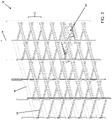
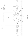
- FIG. 1 is a photograph of the front view of a single level or shelf of a typical Dutch-style multilayered grow bed. The photograph clearly shows mushrooms at different stages of development, mushrooms growing in groups (often referred to a "clusters"), mushrooms growing upright, mushrooms grown sideways, and so forth.
- Mushrooms are a very delicate produce and using vacuums and/or suction cups to detach a mushroom from the substrate will most likely cause damage to that mushroom making it non-saleable. Sometimes the damage on the mushroom is not noticeable initially but while sitting in the cooler (e.g., within 24 hours) bruising will become more evident.
- the issue with transporting the growing medium to the harvester is that it requires a lot of energy and it disturbs the growing environment of the mushrooms.
- a mushroom growing room has been specifically designed to create an evaporative environment for the ideal mushroom growing environment through the controlling of air flow, humidity, and temperature. That is, by removing the mushrooms and growing medium from this environment you are adversely affecting the growing of mushrooms.
- US Pat. No. 5,058,368 (US '368) and US Pat. No. 5,471,827 (US '827) describe the use of cameras to capture optical images of mushrooms on a bed, from which the 2D coordinates of the mushroom centroid and diameters are extracted using image processing techniques.
- US '368 and US '827 however lack the ability to infer the depth of the mushroom making it difficult to determine the true 3D centroid and diameter of the mushrooms on the bed.
- US Pat. No. 8,033,087 attempts to solve the prior restriction of fixed cameras by introducing a 2D movable camera which can capture images of the mushrooms at different locations of the bed and therefore is able to infer the depth of the mushroom centroids, but not precise 3D mushroom geometry from the instability of 2D image processing algorithms due to the dynamic properties mentioned above.
- US '087 also relies on the use of grasping technologies that use additional means of measurements to complete the grasp of the mushroom, which is similar to the approach presented in US 2005/0268587 .
- US Pat. No 9,730,394 (US '394) attempts to use complex image processing techniques to capture and extract mushrooms, their centroids, diameters, and neighbor information from the captured images, but US '394 also relies on the use of force controlled grasping technology to account for the uncertainty of measurements generated by the image processing technique.
- NL1028906C2 discloses a picking device for picking mushrooms including a gripping member which is adapted to engage the stalk of a mushroom.
- the gripping member includes protrusions shaped substantially the same as the stalk of the mushroom.
- CN108605663A discloses a mushroom-picking device including an articulated sawtooth for gripping a mushroom.
- the following provides a system, method, and apparatus for automated mushroom harvesting that addresses the above challenges and can enable an industrial standard of mushroom harvesting while adapting to and leveraging the existing infrastructure to avoid large modification costs.
- an automated harvester comprising: a frame; a vision system supported by a rail at one end of the frame, the vision system configured to scan a growing bed under the frame; and a picking system moveable within a working area defined by the frame, the picking system comprising a plurality of flexible fingers for gripping mushrooms, the fingers being controlled by the picker to move towards and away from each other each finger being configured to conform around a cap of the mushroom in response to pressure applied against the fingers by the mushroom during a picking operation.
- a picking system for an automated harvester for mushrooms comprising: a gantry coupled to a frame of the automated harvester, the gantry permitting translation of the picking system in a plurality of directions, including vertical translation; a gripper comprising a plurality of servo-driven elements to provide multiple degrees of freedom of motion in addition to the vertical translation; and a plurality of flexible fingers for gripping mushrooms, the flexible fingers being controlled by the gripper to move towards and away from each other, each finger being configured to conform around a cap of the mushroom in response to pressure applied against the fingers by the mushroom during a picking operation.
- a vision system for an automated harvester comprising: a rail sized to extend across a growing bed and be supported above the growing bed by a frame of the automated harvester; a plurality of 3D scanners spaced along the rail, each 3D scanner comprising: a laser; a slot to permit a laser line to be directed by the laser towards the underlying growing bed; at least one camera to capture data detectable from the laser line emitted from the slot; and a processing unit to process the captured data.
- a method of harvesting mushrooms using an automated harvester comprising: instructing the automated harvester to move along a growing bed to scan mushrooms in the growing bed using a vision system comprising a plurality of 3D scanners spaced along a rail of a frame of the harvester; capturing data from the 3D scanners; generating a 3D point cloud from the captured data; using the 3D point cloud to identify candidate mushrooms and generate a picking sequence; instructing the automated harvester to move along the growing bed and to operate a picking system to target candidate mushrooms in the picking sequence; and for each candidate mushroom, controlling flexible fingers of a gripper to move towards and away from each other, each finger being configured to conform around a cap of the mushroom in response to pressure applied against the fingers by the mushroom during a picking operation.
- a computer readable medium comprising computer executable instructions for performing the above method.
- the system in one implementation, may be referred to herein as an "automated harvester", having at least an apparatus/frame/body/structure for supporting and positioning the harvester on a mushroom bed, a vision system for scanning and identifying mushrooms in the mushroom bed, a picking system for harvesting the mushrooms from the bed, and a control system for directing the picking system according to data acquired by the vision system.
- an automated harvester having at least an apparatus/frame/body/structure for supporting and positioning the harvester on a mushroom bed, a vision system for scanning and identifying mushrooms in the mushroom bed, a picking system for harvesting the mushrooms from the bed, and a control system for directing the picking system according to data acquired by the vision system.
- Various other components, sub-systems, and connected systems may also be integrated into or coupled to the automated harvester as discussed in greater detail below.
- the vision system as described herein can be implemented in a "rail" or other module integrated into the apparatus of the automated harvester to position vision components for scanning and acquiring data of the underlying mushroom bed.
- the mushroom bed is meant to support a substrate in which mushrooms grow and are to be harvested.
- the automated harvester described herein is configured to move along existing rails of the growing bed, e.g., in a Dutch-style multilayered growing bed to scan and pick periodically and preferably continuously without the need for manual harvesting.
- the vision system can detect mushrooms, their properties (e.g., position, size, shapes, orientations, growth rates, volumes, mass, stem size, pivot point, maturity, and surrounding space), statistics, and the strategies required for instructing the picking system for autonomous mushroom harvesting.
- the rail or module of the vision system can include a precisely machined structure designed to hold one or multiple 3D data acquisition devices or scanners, data routing devices, communication modules, and one or more processing units. Power can be provided by a separate rail or module, herein referred to as a "battery rail".
- the automated harvester may traverse mushroom growing beds and may contain mushroom grasping and manipulating technologies (embodied by the picking system), therefore increasing the ability of the overall system to harvest mushrooms of the highest quality and yield within the requirements of industrial production.
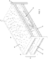
- FIG. 2 illustrates an example of a standard (e.g., Dutch-style) multilayered growing bed assembly 10 for indoor mushroom growing. It can be appreciated that some components of the growing bed assembly 10 are omitted from FIG. 2 for ease of illustration.
- the growing bed assembly 10 is constructed to create a plurality of layers or levels 12 (one of which is numbered in FIG. 2 ).
- the growing bed assembly 10 includes a number of vertical posts 14 and a pair of side rails 16 at each level 12.
- the vertical posts 14 and side rails 16 are positioned at a standard distance from each other by a number of cross beams 18.
- the cross beams 18 tie the vertical posts 14 together to form each level 12 and support the substrate, i.e., growing medium such as compost.
- Each cross beam 18 includes a number of square-shaped apertures in this example through which square beams (not shown) can be inserted to support the substrate.
- FIG. 2 Also shown in FIG. 2 is an automated harvester 20 that is positioned on one of the levels 12 to illustrate its adaptability within the constraints of the standard growing bed assembly 10.
- FIG. 3 illustrates a portion of the growing bed assembly 10 to provide a close view of a first level 12 at which the automated harvester 20 is positioned and a second level 12 above the automated harvester 20. Also shown in FIG. 3 is a substrate 22 (i.e. growing medium) at each level 12 in which a number of mushrooms 24 are growing (see also FIG. 1 for a real-world view). It can be appreciated that in FIG. 3 one of the vertical posts 14 on the near side has been removed to provide a better view of the automated harvester 20.
- FIG. 3 illustrates more clearly the space constraints imposed by the assembly 10 that are addressed by a number of unique features of the automated harvester 20 that permit adaptability to the existing standard infrastructure without the need to incur significant retrofit costs.
- the configuration of the automated harvester 20 also eliminates the potentially harmful effects felt by manual pickers which experience the aforementioned environmental conditions and the tight picking area.
- FIG. 4 provides a front-end view of the automated harvester 20 as seen in FIG. 3
- FIG. 5 provides a rear-end view of the automated harvester 20 as seen in FIG. 3
- a series of irrigation sprinklers 26 extend downwardly from the level 12 above.
- the automated harvester 20 is configured to include a longitudinal slot or channel 28 through the components of the harvester 20 that would otherwise interfere with the sprinklers 26, providing yet another example of adaptability with the standard assembly 10.
- the side rails 16 include an upper track 30 along which wheel assemblies 32, 34 of the automated harvester 20 travel.
- the substrate 22 in this example is filled to a level that is approximately +/- 5 cm relative to the height of the side rails 16. Because of this potential variation, the body of the automated harvester 20 is configured to be positioned as close to the upper level 12 as possible while accommodating the irrigation sprinklers 26.
- the first wheel assembly 32 on the left side of this view comprises a one-sided flange type wheel that allows the automated harvester 20 to operate on beds that have intolerant widths between the side rails 16, also referring to herein as the "floating side".
- the second wheel assembly 34 on the right side of this view includes a wheel profile that matches the rail profile (i.e. the profile of the track 30) and includes a two-sided flange.
- the second wheel assembly 34 may also be referred to herein as the "fixed side”.
- This wheel assembly 34 is configured to stay relatively “fixed” on the track 30 of the corresponding side rail 16 to maintain the position of the automated harvester 20 relative to this rail 16.
- the other (floating) side of the automated harvester 20 can tolerate changes in width.
- FIG. 5 in this rear-end view one can see a battery rail 54 in the foreground (to be identified and described below).
- This end of the automated harvester 20 is also configured to accommodate the sprinkler heads 26 by providing a continuation of the channel 28.
- the end views in FIGS. 4 and 5 also emphasize the vertical space between levels 12 and how the automated harvester 20 is sized to just fit in that space. In this example, a suitable tolerance is 1 cm such that any closer and the automated harvester 20 could end up jamming somewhere along the levels 12 by hitting the frame/support bars 14, 16, 18.
- the beds provided at each level 12 may get damaged over time causing bends or other misalignments, which can interfere with the automated harvester 20 while it traverses a level 12.
- FIG. 6a provides a close-up view of the indexed type wheel 34
- FIG. 6b provides a close-up view of the floating type wheel 32
- the indexed type wheel 34 includes an outer flange 40 and an inner flange 42
- the floating type wheel 32 includes only an inner flange 46.
- FIGS. 6a and 6b also provide a closer view of a brake assembly 44 to enable braking operations to be applied to the tracks 30 over which the automated harvester 20 travels during scanning and picking operations. Further detail of this braking operation is provided below.
- the wheels 32, 34 of the automated harvester 20 are located at the four corners of the harvester's frame.
- the indexed wheel profile matches the profile of the track 30 of the standard bed rail 16, preventing it from sliding left/right.
- the floating wheel profile having a one-sided flange 46 with a flat wheel profile allow for beds that have damaged or high tolerance bed widths.
- the diameter of the wheels 32, 34 can be chosen to accommodate space restrictions, i.e., not too big to restrict gantry motion, while being not too small to allow for smooth crossing rail gaps/height differences at the point where two rails 16 connect to form a longer rail 16.
- the width of the wheel 32, 34 and the wheel's support leg are designed to minimize the "shadow" of the wheel/leg over the substrate 22 of the bed.
- the pulley transmission of the wheels 32, 34 can have a specific gear ratio used to increase the traction/power of the wheels 32, 34 on the rails 16, while both the left and right rear wheels 32, 34 are independently driven to allow for more power but also traction differences between left/right rails 16.
- the rear wheels 32, 34 also have a physical brake mechanism 44 that engages when the automated harvester 20 is picking at extremely high picking speeds to prevent shaking and position loss due to wheel slippage or sliding. Without this brake mechanism 44, the speeds required for industrial harvesting may not be achievable on these rails 16 without the potential for significant damage.
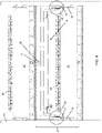
- FIG. 7 a side-view of a level 12 of the assembly 10, with an automated harvester 20 positioned therein, is shown.
- This side-view illustrates the functional components of the automated harvester 20, namely a vision system rail 50 at one end of the harvester's frame, a picking system 52 coupled to and moveable within the extent of the frame, and a battery rail 54.
- the vision system rail 50 and the battery rail 54 are separated from each other by a pair of upper harvester side rails 56 and a pair of lower harvester side rails 57, which all collectively form the frame of the automated harvester 20.
- Also seen in FIG. 7 are the front and rear indexed wheels 34.
- FIG. 1 the front and rear indexed wheels 34.
- the picking workspace also illustrates the workspace of the picking system 52, which in one implementation provides an approximately 2000 mm span in the lateral or "Y" direction (i.e., the width) - including the picking workspace and telescoping workspace in that direction (explained in greater detail below).
- the picking workspace also comprises approximately 850 mm in the longitudinal or "X" direction (i.e., the length) and approximately 130 mm in the vertical or "Z" direction (i.e., the height).
- FIG. 8 illustrates a perspective view of the automated harvester 20 in isolation to provide additional detail of the configuration described above.
- the vision system rail 50 at the front of this view incorporates a portion of the channel 28 to accommodate the irrigation sprinklers 26 and extends between opposing rails 16 on a level 12 of the assembly 10.
- the battery rail 54 at the rear of this view also incorporates a portion of the channel 28 and extends between opposing rails 16 on the level 12.
- the side rails 56, 57 extend between the vision system rail 50 and the battery rail 54 and create open areas on either side of the frame. As discussed below, this permits the gripper 64 of the picking system 52 to extend beyond the edges of the bed, e.g., to complete a harvesting operation by placing a picked mushroom outside of the bed.
- the upper side rails 56 also include linear guides along the bottom thereof to facilitate translation of the picking system 52 within and relative to the frame of the automated harvester 20.
- the wheels 32, 34 and brake mechanisms 44 are also visible in this view.
- a gantry 60 which corresponds to the components of the picking system 52 that couple the picker 62 to the frame of the automated harvester 20 and which enable movement or translation of the picking system 52 in the X (longitudinal), Y (lateral), and Z (vertical) axes.
- the gantry 60 can include a motor for moving the gripper 64 in the X direction, a motor for moving the gripper 64 in the Z direction, and a motor for moving the gripper 64 in the Y directions as discussed in greater detail below. Movement in the X direction is aided by the liner guides provided by the upper side rails 56 and the lower side rails 57 as can be appreciated from the view in FIG. 8 .
- the battery rail 54 contains all power-related mechanisms for the automated harvester 20 and contains a battery pack to enable the automated harvester 20 to be cordless. This avoids cords interfering with the growing bed when the cords are dragged over the mushrooms.
- the battery rail 54 also may include one or more battery charging ports for autonomous charging via a dock on lift operation.
- the battery rail 54 also includes network communications antenna to minimize interference from other components of the automated harvester 20 and can be configured to have swappable battery logic to allow for swapping the battery pack while the power is kept on.
- the battery rail 54 is positioned at the back of the harvester's frame and is positioned at a height to clear any possible mushroom fill level or tall mushrooms (e.g., portabellas) and as noted above to include the channel 28 to clear the sprinkler heads above the harvester's frame.
- the frame of the automated harvester 20 needs to fit in a very small/narrow space between the growing bed levels 12 while providing sufficient rigidity to support harvesting mushrooms in an industrial setting.
- the frame should also have the flexibility to deal with high intolerance of the growing bed assemblies 10.
- the frame is designed to be tolerant of high compost fill-height and relatively tall mushrooms.
- dowels and alignment blocks can be used for jointing the frame components together. This can assist in preventing frame skewing, misalignments, and position intolerance in the lateral, longitudinal, and vertical directions.
- the upper part of the reinforced frame can be used for control/power wiring channels and tracks to allow for unrestricted motion in the lower part of the frame.
- the upper part of the frame also contains the linear guides (as noted above) that the harvester 20 relies on for position reference and rigidity.
- the left side of the frame is used as the indexed side of the frame i.e. the mounting points on the left side are precise and have tight tolerances, while the right side of the frame has higher tolerance mounting points to support floating connections. This enables the required high-precision positioning of the picking system 52 even though the growing beds have high tolerances and variability.
- the frame can use aluminum and stainless-steel components for weight and food-safety considerations.
- Any plastic components can be chosen to be food-safe grade, while the mechanisms that normally require lubricant can be chosen to have self-lubricating properties.
- the automated harvester 20 can also utilize covers that cover most of the body allowing the automated harvester 20 to be wiped-down to comply with food-safety regulations.
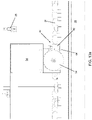
- the top view of the automated harvester 20 shown in FIG. 9 provides a plan view of the picking workspace afforded to the automated harvester 20.
- an internal picking workspace in the lateral or "Y" dimension (width) and an additional telescoping drop off workspace in the lateral or "Y” dimension wherein the gripper 64 can telescope beyond the side rails 16 of the bed.
- the automated harvester 20 can be configured to provide approximately 1250 mm internally and 2000 mm telescoping, providing 375 mm of reach beyond the rails 16.
- FIGS. 10 and 11 provide additional elevation views showing the vertical or "Z" portion of the picking workspace, and the lateral or "Y” (internal) picking workspace afforded by the harvester's frame.
- the gantry's X axis is connected to the frame via the linear guides discussed above that are precisely positioned and aligned on the top of the frame.
- the gantry 60 is driven along its X axis via a rack and pinion mechanism to allow for multiple independent X axes i.e. independent picking gantries 60 within the same frame.
- the gantry 60 slides along its X axis over the linear guide using pillow blocks with internal rollers.
- the left and right side follow the same indexed for left and floating for right side mechanism as described previously to prevent binding/dynamic friction when bed intolerances that skew the frame are encountered.
- the gantry's rack and pinion for its X axis can have a spring-loaded mechanism (located on the subassembly for permitting movement in the Z axis - described below) that keep the correct meshing between gears even when the harvester's frame encounters skewing from the rails 16.
- the component(s) of the gantry 60 that permit movement along its Z axis (height) is/are coupled relative to the component(s) of the gantry 60 that permit movement along its X axis and is/are custom designed for compactness while providing very high stroke length (e.g., 130mm) relative to the overall height of the gantry's Z axis.
- the gantry 60 can be driven in the Z direction via high pitch leadscrew (for speed) with a self-lubricating anti-backlash nut, supported by the linear guide rail that is self-cleaned using a pad.
- the gantry 60 can be driven in the Z direction by a pulley mechanism with a specifically chosen ratio to prevent the gantry 60 from dropping in case of power loss of the motors.
- the pulley mechanism can also have a spring-loaded belt tensioning mechanism to help with dynamic tension adjustments.
- the left and right side of the gantry's Z axis components can be independently driven for performance and are consistent with the indexed vs floating approach described above.
- the bottom of the gantry's Z axis subassembly can have spring-loaded wheels which travel along v-groove lower rails 57 mounted on the bottom of the harvester frame to help align the gantry 60 in the Z axis during motion as well as providing a dynamic meshing mechanism for the rack and pinion used to permit movement of the gantry 60 along the X axis.
- the gantry's Z axis sub-assembly can be enclosed within covers to reduce water/humidity damage and have an active cooling mechanism for the motors.
- the component(s) of the gantry 60 that permit movement along its Y axis (width) is/are coupled relative to the component(s) of the gantry 60 that permit movement along its Z axis and serve(s) the purpose of manipulating the position of the gripper 64 in the Y direction along the width of the mushroom bed as well as to telescope outside of the bed, e.g., up to 375 mm to either side of the rails 16.
- the total stroke of the gantry 60 along its Y axis can therefore be up to two meters.
- the gantry's Y axis can be split into two parallel axes, i.e., Y1 and Y2.
- the telescoping mechanism allows the automated harvester 20 to deliver mushrooms (i.e. position the gripper 64) outside of the bed while also being able to avoid bed posts when the harvester 20 is moving forward.
- the gantry's Y axis is configured to have a very narrow vertical profile to be able to traverse the bed above the mushrooms and below the sprinklers 26.
- the gantry's Y axis can be both belt and leadscrew-driven in order to achieve high precision, yet also very high speed, in order to pick and deliver mushrooms quickly without damaging them.
- FIG. 12 provides a side view of the automated harvester 20 and illustrates the picking workspace in the X and Z directions. From this view, the gantry's Z axis can be seen, as well as its drive mechanism, including a belt driven leadscrew 70 and the linear guide rail. With a lower pitch leadscrew and with a high pully ratio, the gantry 60 should not drop vertically with a power loss. This can be important since if the gantry 60 were to drop vertically with a power loss, it could damage (e.g. crush) the underlying mushrooms 24 or get stuck in the substrate 22. This is in contrast to using a braking mechanism that would be heavy and slow down performance.
- the gripper 64 is also visible in this view and includes a plurality of fingers 74 depending therefrom. The gripper 64 (and picking system 52) controls not only the positioning of the gripper 64 but also the actuation of the fingers 74 to delicately pick the mushrooms 24. Also shown in FIG. 12 is a brake mechanism 44 located below the battery rail 54.
- FIGS. 13a and 13b provide enlarged views of the braking mechanism 44 in the disengaged and engaged positions respectively. It can be appreciated that in the configuration shown herein, the braking mechanisms 44 are only used on the rear wheels 32, 34 (beneath the battery rail 54) but could be used on all four wheels 32, 34 if desired.
- the brake mechanism 44 can be driven by a lead screw as best seen in FIG. 13b to drive a brake pad 84 towards the track 30 atop the rail 16 to create a frictional braking action.
- the brake pad 84 can be driven from a brake body 82.
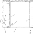
- FIG. 14 provides a view of the underside of the automated harvester 20 to illustrate components of the vision system rail 50 not seen in previously described views.
- the vision system is supported by or contained within the vision system rail 50 and for ease of illustration the vision system rail 50 will be referred to below.
- the vision system rail 50 is located at the front of the harvester's frame since the automated harvester 20 is configured to only need to move forward after scanning mushrooms 24 to align the gripper workspace with the scanned data. It may be noted that if the automated harvester 20 moves forward and backward after scanning, the scan data could become invalid since reversing wheel movement can accumulate position errors through backlash or wheel slippage on the rails 16.
- the position of the vision system rail 50 relative to the gripper's workspace is important for successful picking of large bed sections at once.
- the vertical positioning of the vision system rail 50 is also important since it needs to clear all obstacles in the bed, similar to the battery rail 54 as discussed above.
- the vision system rail 50 also needs to allow for the largest possible height difference between the 3D scanners 100 and the mushroom 24 growing from the substrate 22.
- the width of the vision system rail 50 is also maximized to allow the scanners 100 to capture not just the growing bed, but also a distance beyond the rails 16 (e.g., 300 mm of the 375 mm outside both the left and right side of the bed) to enable the detection of a drop-off location and for post detection.
- the vision system rail 50 can also include rail reinforcements to generate rigidity due to the very narrow profile.
- the vision system rail 50 supports a set of six 3D scanners 100, each having a pair of camera apertures 102 (for capturing images below the rail 50) and a laser slot 104 for permitting a laser line 106 (see FIG. 15 ) to project from the vision system rail 50 onto the mushrooms 24 below.
- the camera holes 102 can be sealed with optical-grade clear panels. Since the vision system rail 50 is enclosed, the electronics within it can be passively cooled using the thick and large aluminum surface of the vision system rail 50 to prevent the use of active cooling (e.g., fans) thus preventing humidity from entering the vision system rail 50 during cooling.
- the vision system rail 50 can have its multiple 3D scanners 100 aligned in one straight line to effectively form a combined (e.g., 1.9 m long) line scanner within tightly constrained vertical spaces, while achieving sub-millimeter accuracy and very high data throughput.
- the vision system rail 50 can also generate color information that is overplayed on a 3D point cloud allowing for real-time disease detection, mushroom quality and type identification.
- the vision system rail 50 can also include external air temperature and humidity sensors for the grow room environment as well as contactless soil temperature sensors.
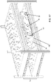
- FIG. 15 illustrates how the multiple 3D scanners 100 can work with each other to scan the entire width of the bed (or more) with only a limited amount of vertical space.
- LSPAN refers to "Laser Scanner Span Angle” and in an example configuration equals 100 degrees.
- LFOV refers to "Laser Scanner line width” and in this example configuration equals 600 mm.
- O refers to the laser line "overlap” and in this example configuration equals 325 mm
- D refers to the distance between the scanners 100 and the substrate 22 and in this example configuration equals 240 mm.
- DMIN refers to a minimum scan distance and in this example configuration equals 100 mm.
- the variables shown in FIG. 15 illustrate that the configuration can use different values, e.g., other LSPANs, other distances between scanners, etc. The example values given herein can be used to maximize visibility of the mushrooms and their stems.
- this view shows that a mushroom 24 that is at the edge of scanner 100 (or under a large angle) can occlude itself, as such it's important to be able to see all sides of the mushrooms 24 for adequate detection.
- the scanner 100 has the scanner 100 close to the edge of the bed allows the scanner 100 to scan the vertical posts 14 to prevent the gripper 64 from hitting it while telescoping, but also allows the vision system to scan for mushrooms 24 on the very edge of the bed, and for other objects of interest that are outside the bed to be detected (e.g., a mushroom delivery platform).
- a 1.9 meter long laser line scanner is created, that has the ability to scan objects even when other objects are occluding it, with a minimum scan distance of 100mm (for full scanning coverage in this configuration). Therefore, the vision system can fit in very tight spaces that require up close scanning.
- the rate at which the scanners 100 scan can be between 1-150 lines per second where a line includes 7700 points that cover the 1.9 meters span (including overlapping points).
- the scanner's resolution in this example can be 0.25 mm in XYZ after processing.
- the resolution/fps/length of the scanner line can be configured for a vast range of applications that require either precision, or speed, or overlapping region, or length of scanner, etc. That is, one can simply modify the parameters listed above and select sensors having different resolutions.
- FIGS. 16 to 18 The vision system during a scanning operation is illustrated in FIGS. 16 to 18 that provide a perspective view of the automated harvester 20 moving along the rails 16 of the bed.
- the combined laser line 106 effectively sweeps over the mushrooms 24 to generate a 3D point cloud for further processing. That is, the physical configuration of the multiple scanners 100 facilitates the scanning of mushrooms 24 within a constrained vertical space.
- FIGS. 19a and 19b perspective views of the gripper 64 are shown in isolation.
- a side view of the gripper 64 is also shown in situ in FIG. 19c .
- the gripper 64 in this example incorporates four degrees of freedom and can perform full hemispherical motion plus is able to open and close a pair of fingers 74. It may be noted that this is the least amount of degrees of freedom required to successfully pick and manipulate mushrooms 24 and was modelled after how humans pick mushrooms 24.
- the gripper 64 In conjunction with movement along the axes of the gantry 60 and the operation of the fingers 74, the gripper 64 can push, pull, twist, tilt, hold, release, and move mushrooms 24 very gently.
- the gripper 64 is load sensitive and thus can feel pressure as it is being applied to the mushrooms 24 so as to not crush them.
- the gripper 64 is connected to the gantry 60 and is controlled to execute advanced manoeuvres to replicate human picking motions. To achieve this, the gripper's four degrees of freedom (i.e., multi-turn spherical manipulator and open/close fingers 74) have a narrow profile in all directions to prevent gripper contact with neighbouring mushrooms 24 during a pick.
- the gripper motor controls and power wiring can be daisy chained to allow for compactness and simplicity of wiring.
- the gripper 64 is capable of tilting, twisting, pushing, pulling, and carrying a mushroom using the specially designed fingers 74 that attach to the gripper 64.
- the fingers 74 attach to the gripper in a specific configuration (e.g., thumb at 0 degrees, left index finger at -165 degrees, right index finger at +165 degrees). This configuration was chosen as the optimal and minimal required number of contact points while generating a geometrical lock on the mushroom 24 for manipulation in any direction without the reliance on finger friction.
- the mechanism for attaching the fingers 74 to the gripper 64 can be adjustable to allow for +/- 20 degree changes in their position as well as how close the index fingers 74 are to the thumb finger. This allows the gripper 64 to target mushroom sizes that differ by 100 mm using the same fingers 74 and gripper 64.
- the fingers 74 can be configured to slide on to the mechanism on to a mounting portion of the gripper 64 from the outside towards the center and can be ratcheted so they can only slide forwards. This helps with easily swapping out fingers 74 for new ones, while remaining stiff when mushrooms 24 apply force in the opposite direction.
- the gripper 64 has the ability to sense closing force on the mushroom 24 to prevent damaging the mushroom 24 during picking effectively mimicking "human force sensing" when picking mushrooms 24.
- the finger 74 may be unibody or made of subcomponents connected to each other (as shown). It can be appreciated that in a unibody construction the possibility of finger parts falling on the mushroom bed i.e. metal hinges or sub-components of a multi-piece finger 74 could be avoided.
- a one-piece construction can have the back of the finger 74 be ridged (thicker), the front be flexible (thinner), and the hinges between thinned out so as to allow for bending radius control and overall desired stiffness of the finger control when in contact with a mushroom 24.
- the overall design of the finger 74 (whether unibody or multi-component) is configured to replicate a human's ability to bend the tips of their fingers under a mushroom cap. If any damage were to occur, it would thus occur under the cap, which is typically deemed acceptable by industry standards.
- the body and tip of the finger 74 are narrow to be able to fit between the tight spaces between mushrooms 24 without contacting neighbouring mushrooms 24.
- the fingers 74 can be covered with food-grade finger cots (i.e., a type of glove) that can be used to extend the life of the finger 74 and provide cleanliness, food-safety, and create a soft barrier between the mushroom's surface and the relatively rougher finger surface.
- the finger 74 If the finger 74 is to touch a neighbouring mushroom 24 during finger insertion, the gloved surface would contact the mushroom 24, while the finger 74 would slide along the internal surface of the glove, thus not damaging the mushroom's delicate surface.
- the finger 74 and its gloves are also intended to be replaced often, which can be done to match a human's glove replacement levels to satisfy established food-safety regulations in the industry.
- the fingers 74 can also be coated to reduce the possibility of disease build-up, as well as irradiated using UVC LED light array as a germicide while in operation to prevent the spreading of disease from one mushroom 24 to another.
- the gripper 64 can include a grasping servo 122, and three primary servos 120, 124, 126 and a body 128. Joint rotation axes of the gripper 64 are arranged orthogonally to each other and intersect in a single point.
- the grasping servo 122 is responsible for actuating the fingers 74 and for sensing grasping force feedback.
- the primary servos 120, 124, 126 can be used for independent actuation of joints to achieve the various orientation angles described above, for movements such as tilting, twisting, etc.
- FIG. 19a illustrates the fingers 74 holding a mushroom 24.
- FIG. 19b provides an enlarged view of what is shown in FIG. 7 and provides an enhanced view of the Z-axis of the gantry 60 and the leadscrew 70.
- Each finger 74 includes a platform 206, a tip 200, an outer beam 202, and an inner beam 204.
- the tip 200 is shaped to allow insertion into tight spaces between mushrooms 24 and to minimize damage to surrounding mushrooms 24 during this process.
- pressure is applied and the fingers 74 fold, as shown in FIGS. 20b and 20c , to geometrically secure a mushroom 24, which allows maximum manipulation forces and minimum impact of friction, which reduces damage to the target mushroom 24.
- pressure is removed, the fingers 74 return to a rest configuration as shown in FIG. 20a .
- the fingers 74 can be structured to limit motion of the joints in order to work as a lever for a steel spring that unfolds the finger 74. In another implementation, these functions have been redistributed to other elements of the construction so that the previously described structure with the steel spring is not required.
- FIGS. 20a-20c demonstrate how the fingers can fold when pressure is applied by a mushroom 24 against the inner beam 204 and the flat portion 201 of the tip 200.
- FIG. 21 illustrates a laser scan line 106 from a side view.
- the vision system can scan a section of the bed (e.g., variable length of section up to 800mm), then move forward into a picking position, and pick mushrooms 24 until no more target mushrooms 24 are available.
- the automated harvester 20 can repeat this process for the rest of the bed.
- the harvester 20 does not need to sequentially work its way from start to end, it can first perform a global scan, then dynamically build a picking schedule based on where the target mushrooms 24 are along the bed, and then execute in that order to maximize effectiveness and to reduce chances of mushrooms 24 growing larger than target size. Any suitable logic can be developed and executed to choose a suitable picking schedule.
- FIG. 21 illustrates the beginning of a scanning operation
- FIG. 22 illustrates approximately the middle of the scanning operation
- FIG. 23 illustrates the end of the scanning operation with the gripper 64 beginning to position itself to pick a target mushroom 24 in the section that has just been scanned.
- FIGS. 24 through 29 illustrate a picking operation applied to a target mushroom 24.
- the view is zooming in on the picking approach wherein the fingers 74 are inserted around the mushroom 24 so as to carefully avoid contact with neighboring mushrooms 24.
- the automated harvester 20 can be programmed to allow for slight contact, which can be an adjustable parameter.
- FIG. 25 the view further zooms to illustrate a close up of the fingers 74 as they begin to form contact with the cap of the mushroom 24.
- the gripper's servos can begin closing (actuating) the fingers 74 over the mushroom 24. When contact is formed in conjunction with finger actuation, the fingers 74 begin conforming around the mushroom 24.
- the fingers 74 come into contact with the mushroom 24. Now, it can be seen that the fingers 74 are in the correct position to manipulate and thus "pick" the mushroom 24 from the substrate 22. It can be appreciated that the intention here is to have the tip 200 of the fingers 74 be located on the underside of the cap of the mushroom 24, which is an acceptable area to create slight damage (while the intention is to ideally have zero damage). As such, if any damage was to occur (unintentionally), it would occur on the bottom of the cap. With the tips 200 under the mushroom 24, the plurality of fingers 74 (e.g., the three fingers 74 shown in FIG.
- FIG. 27 illustrates a tilt/twist/push/pull action (or a different combination of those actions) that is being applied to the mushroom 24 towards as mush empty space as is available, so as to separate the mushroom stem from the substrate 22 without damaging neighboring mushrooms 24 or hitting other obstacles.
- FIG. 28 illustrates a picked mushroom 24 being lifted away from the bed
- FIG. 29 illustrates a safe transport position for the mushroom 24 that is out of the way of the other unpicked mushrooms 24. For example, some taller mushrooms may end up with a horizontal transport position to reduce the likelihood of hitting anything while travelling to a drop-off location.
- FIG. 30 provides a zoomed out end view of a mushroom 24 being transported along the gantry's Y axis
- FIG. 31 illustrates the telescoped position of the Y axis beyond the extents of the bed to enable the mushroom 24 to be delivered to a drop off location 300 outside the bed.
- FIG. 31 illustrates an outermost position and in this configuration can be up to 375 mm on either side of the automated harvester 20.
- the drop off location 300 can be the location for another robot, a packaging box, or a human hand to package the picked mushroom 24.
- the automated harvester 20 can operate the vision system rail 50 and picking system 52 to scan and pick any and all mushrooms 24 grown using an existing multi-layer assembly 10.
- the process of harvesting in a growing room typically begins with the early forming of mushrooms 24 on the growing bed, i.e. on the growing medium or substrate 22.
- Specific mushrooms 24 are known to grow quicker than other mushrooms 24 and, as such, the apparatus needs to travel the beds at the different levels 12 to harvest the isolated early mushrooms 24. From this point on, the plan can be formed to operate a continuous travel path over the beds, monitoring the growth of the mushrooms 24 and harvest off mushrooms 24 once they reach optimal size.
- a single automated harvester 20 can be deployed at one level 12 after another, or multiple harvesters 20 can be deployed on multiple levels 12 at the same time and used individually to scan and target mushrooms 24 for picking.
- the automated harvester 20 can be brought into a mushroom 24 growing room using a lift (not shown), which can also function as a carrying cart.
- the lift can be attached to the bed frames by a rack and pinion mechanism.
- a drive motor on the lift can be used to index up and down the rack to raise and lower to the different levels 12.
- the controller on the lift can position the lift to be parallel with a specified level 12 of the mushroom bed so that the harvester 20 can drive off the lift and onto the side rails 16 of the mushroom bed as illustrated in FIG. 2 .
- the vision system rail 50 moves along the bed to scan the mushrooms 24 growing on the substrate 22 and generates a 3D point cloud of the mushroom bed section that was scanned.
- the data acquired from the scanners 100 can be sent to a local processor unit and/or can also be sent to a centralized server or host computer (not shown).
- the data collected by the centralized server may be used for optimization of the harvesting process.
- the local processor applies filters and user parameters to determine the optimal picking strategy. Once a section is finished being scanned the local processor unit determines if there are any candidates to harvest in the section based on the scanned data it received.
- the harvester continues scanning the next target section and repeats the process until it reaches the physical end of the bed level. Once the end of the bed level has been reached the harvester reverses back to the lift without scanning. The Lift then raises or lowers the harvester to a new bed level and the process repeats.
- the local processor unit determines that there was at least one candidate mushroom 24 within in the scanned section, the local processor unit instructs the harvester 20 to move and stop over that section and harvest the mushroom(s) 24.
- the strategy to detach the mushroom from the soil (substrate) incorporate several factor including, but not limited to, finger placement, angle of approach, mushroom shape, mushroom diameter, mushroom height, mushroom pivot point, and action(s) to perform (e.g., twist, pull, tilt, push).
- the fingers 74 are positioned within the work area above the mushrooms 24 and the gantry lowers them to grab mushroom with the fingers 74 and execute the appropriate strategy.
- the mushroom 24 After the mushroom 24 has been detached from the soil (substrate 22) it is raised back into the work area (mushroom is still held by the fingers 74 so it can freely travel to the side of the harvester 20 and the drop off zone 300. It should be noted that only candidate mushrooms are harvested not all the mushrooms. Using the detected natural growth rate of the mushroom, when the harvester 20 returns to a specific section mushroom which were not candidates to harvest originally will become candidates in future passes.
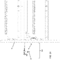
- FIG. 32 illustrates computer executable instructions that may be executed to perform a scanning and picking sequence 400 by a processor (e.g. the above-noted processing unit).
- the process initiates a sequence for a section of the growing bed 404 and determines at step 406 if there are any sections available. If not, the processor determines if any sections should be restarted at step 408. If a section is available to be scanned that section is scanned at step 410 and this generates a 3D point cloud that is processed at step 412 for data representing that section.
- the processor categorizes mushroom candidates by their properties (determined from the 3D point cloud acquired using the multiple scanners 100) and the processor extracts target mushrooms 24 from the candidate list at step 416.
- a global picking strategy is generated for the target mushrooms 24.
- the processor generates a local picking strategy at step 422 and sends instructions to the automated harvester 20 at step 424 for grasping and picking.
- the harvester 20 provides feedback on the picking operation at step 426 and the processor determines if the harvest is complete at step 428. If not, target mushrooms 24 are picked by returning to step 420. If so, the processor returns to step 406 until there are no sections available. Once there are no sections to be restarted the process ends at step 430.
- the local processing unit can enter a scanning mode, initialize the harvesting with behavior parameters and instruct the harvester 20 to move a pre-determined length or section over the bed.
- the local data processing unit instructs the 3D scanners 100 to capture and transfer data using data routers in the vision system rail 50.
- the local processing unit can capture and interpret the data received from the 3D scanners 100 to obtain the XYZ point cloud while the system is in motion.
- mushroom candidates and their features such as position, size, shape, orientation, volume, mass, and surrounding empty or occupied space is extractable with high precision and repeatability.
- mushroom cap features both extracted from the point cloud, mushroom stem height, orientation, and pivot point are also available.
- the process can be repeated for the remainder of section on the bed, from which mushroom statistics can be calculated.
- the data can also used to predict growth rates and locations of mushrooms allowing for the optimization of the harvest yield, speed, and quality.
- a filtering stage can be performed to extract the mushrooms 24 that satisfy the requirements set by predetermined or predictive parameters.
- the local processing unit can calculate a global strategy that specifies the order of picking which is to be performed by the harvesting unit, taking mushroom cluster density, surrounding space, and timing into consideration as discussed above and shown in FIG. 32 .
- the local processing unit calculates local strategies that determine the precise picking strategy required to pick the mushroom in the most optimal way while minimizing external contact and damage that may appear of the mushroom upon contact.
- the local strategy for each mushroom 24 can include calculating the optimal picking approach, points of contact with the harvesters grasping technology, picking motion, and picking direction.
- the local strategy is transferred over to the harvesting unit along with the mushroom features, where the harvesting unit performs the instructed task and provides the picking outcome feedback to the local processing unit.
- the local processing unit has the ability to control to harvesting unit drop off location and procedure for the mushrooms 24 that have been picked. The process is repeated for the remainder of the mushrooms selected by the global strategy, and then repeated for the remainder of the sections that have been selected.
- the automated harvester 20 can also include a human machine interface (not shown), which can be configured as a control panel that is mounted on the harvester 20.
- the interface can also have a portable wireless equivalent called a control client.
- the interface displays current information about the harvester 20 such as current status, power levels, warnings or errors, etc., while providing the ability to control most actions of the harvester 20.
- Both local and portable versions of the interface can include emergency stop buttons for safety precautions which halt all physical motion on the device when pressed.
- the portable control client can be useful when the harvester 20 is out of reach and an unexpected situation occurs.
- the local control panel can interact with the user for modes such as pick assist where the machine can pause or request user interaction such as changing fingers or battery.
- the automated harvester 20 described herein differentiates itself from prior attempts at automated mushroom harvesting by arranging one or more scanners 100 as shown in FIG. 15 to cover the width of the mushroom growing bed, instead of the use of single, movable, or multiple 2D cameras as used in prior attempts.
- the present method processes 3D point data to extract mushroom information and their precise properties instead of using image processing techniques to process optical information extracted from 2D images.
- the presented apparatus does no rely on the optical properties of mushrooms captured by cameras, i.e. the color, intensity, and optical features but rather the pure geometrical data of the mushroom growing bed including the ground, immature mycelium formations, mushrooms, and any other formation or object that may appear.
- the automated harvester 20 described herein also does not need to rely on environmental conditions such as ambient light variations, i.e. can work with artificial or natural light and without the presence of environmental light.
- the present apparatus and its arrangement of 3D scanners 100 provides several areas of scanner overlap therefore overcoming issues of mushroom self-occlusion.
- the apparatus described herein can consistently extract precise geometric information for the whole mushroom cap surface, partial stem surface, the empty or occupied space surrounding the mushroom, and the ground on which it grows on instead of simply the 2D/3D mushroom centroid and their diameter as per prior attempts.
- the present solution can also calculate the approach, gripper-to-mushroom contact points, and global and local mushroom pick strategies with the highest precision without the need for any additional measuring devices to assist the grasping and picking of the mushrooms.
- the present system reduces grasping contact forces and the chance of collision with neighboring mushrooms or obstacles to a minimum during the grasping approach, contact, and picking motion.
- the present solution can also use mathematical models on the captured 3D data to extract or predict the properties of mushrooms 24 such as their position, size, shapes, orientations, growth rates, volumes, mass, stem size, pivot point, and maturity.
- the present system can also predict the time at which the mushroom 24 will reach pre-defined maturity and optimize its picking strategy to maximize yield of said pre-define target or goal.
- the present system can detect the presence, position, and communicate with external devices which are used to aid the process of harvesting, e.g., control devices, packaging devices, product conveying, and product or robot transportation devices.
- any amount refers to the variation in that amount encountered in real world conditions of producing materials such as polymers or composite materials, e.g., in the lab, pilot plant, or production facility.
- an amount of an ingredient employed in a mixture when modified by about includes the variation and degree of care typically employed in measuring in a plant or lab producing a material or polymer.
- the amount of a component of a product when modified by about includes the variation between batches in a plant or lab and the variation inherent in the analytical method. Whether or not modified by about, the amounts include equivalents to those amounts. Any quantity stated herein and modified by "about” can also be employed in the present system, method and apparatus, as the amount not modified by about.
- the properties of mushrooms include their position within the mushroom growing bed (i.e. their coordinates), size of the mushroom cap, shapes of the mushroom caps, orientations of the mushrooms (tilted, straight and so forth), growth rates, volumes, mass, stem size, pivot point, maturity, and surrounding space (distance between mushrooms).
- any module or component exemplified herein that executes instructions may include or otherwise have access to computer readable media such as storage media, computer storage media, or data storage devices (removable and/or non-removable) such as, for example, magnetic disks, optical disks, or tape.
- Computer storage media may include volatile and non-volatile, removable and non-removable media implemented in any method or technology for storage of information, such as computer readable instructions, data structures, program modules, or other data.
- Examples of computer storage media include RAM, ROM, EEPROM, flash memory or other memory technology, CD-ROM, digital versatile disks (DVD) or other optical storage, magnetic cassettes, magnetic tape, magnetic disk storage or other magnetic storage devices, or any other medium which can be used to store the desired information and which can be accessed by an application, module, or both. Any such computer storage media may be part of the automated harvester 10, any component of or related thereto, etc., or accessible or connectable thereto. Any application or module herein described may be implemented using computer readable/executable instructions that may be stored or otherwise held by such computer readable media.
Claims (15)
- Automatisierte Erntemaschine (20) für Pilze, umfassend:einen Rahmen;ein durch eine Schiene (50) an einem Ende des Rahmens getragenes Bildverarbeitungssystem, wobei das Bildverarbeitungssystem dazu konfiguriert ist, ein Anbaubeet (10) unter dem Rahmen abzutasten; undein Pflücksystem (52), das innerhalb eines durch den Rahmen definierten Arbeitsbereichs bewegbar ist, wobei das Pflücksystem (52) eine Vielzahl von flexiblen Fingern (74) zum Greifen von Pilzen (24) umfasst, wobei die flexiblen Finger (74) durch einen Pflücker gesteuert werden, um sie zueinander und voneinander weg zu bewegen, wobei jeder Finger (74) dazu konfiguriert ist, sich als Reaktion auf Druck, der durch den Pilz (24) während eines Pflückvorgangs gegen die Finger ausgeübt wird, um eine Kappe des Pilzes (24) anzupassen.
- Erntemaschine (20) nach Anspruch 1, ferner umfassend eine Batterieschiene (54), die durch den Rahmen getragen ist, wobei die Batterieschiene (54) mindestens eine Batteriequelle zum Antreiben der automatisierten Erntemaschine (20) umfasst.
- Erntemaschine (20) nach Anspruch 1 oder Anspruch 2, ferner umfassend ein Gerüst (60) zum Ermöglichen einer Bewegung des Pflücksystems (52) während Pflückvorgängen, und wobei optional das Gerüst (60) zum Bewegen des Pflücksystems (52) in vertikaler, seitlicher und Längsrichtung konfiguriert ist.
- Erntemaschine (20) nach einem der Ansprüche 1 bis 3, ferner umfassend eine Verarbeitungseinheit zum Erfassen von Daten unter Verwendung des Bildverarbeitungssystems, Erzeugen eines Pflückablaufs aus den erfassten Daten und Anweisen der automatisierten Erntemaschine (20), sich entlang des Anbaubeets (10) zu bewegen, um Abtast- und Pflückvorgänge durchzuführen, und wobei das Bildverarbeitungssystem optional Folgendes umfasst:eine Schiene (50), die so bemessen ist, dass sie sich über ein Anbaubeet (10) erstreckt und über dem Anbaubeet (10) durch einen Rahmen der automatisierten Erntemaschine (20) getragen wird;eine Vielzahl von 3D-Scannern, die entlang der Schiene beabstandet ist, wobei jeder 3D-Scanner Folgendes umfasst:einen Laser;einen Schlitz, um zu ermöglichen, dass eine Laserlinie durch den Laser auf das darunter liegende Anbaubeet gerichtet wird; mindestens eine Kamera zum Erfassen von Daten, die von der von dem Schlitz emittierten Laserlinie erkennbar sind; undeine Verarbeitungseinheit zum Verarbeiten der erfassten Daten.
- Erntemaschine (20) nach einem der Ansprüche 1 bis 4, wobei das Bildverarbeitungssystem dazu konfiguriert ist, einen Pflückablauf basierend auf den erfassten Daten zu erzeugen, wobei der Pflückablauf einen Satz von Anweisungen für ein Pflücksystem (52) der automatisierten Erntemaschine (20) umfasst.
- Erntemaschine (20) nach einem der Ansprüche 1 bis 5, wobei das Pflücksystem (52) einen Greifer (64) umfasst, wobei der Greifer (64) eine Vielzahl von servogesteuerten Elementen umfasst, um mehrere Freiheitsgrade der Bewegung zusätzlich zu der vertikalen Verschiebung bereitzustellen, und wobei optional die servogesteuerten Elemente vier Freiheitsgrade bereitstellen und wobei optional die Finger (74) von einem Körper des Greifers (64) lösbar sind.
- Erntemaschine (20) nach einem der Ansprüche 1 bis 6, wobei jeder Finger (74) ferner einen mit der Spitze (200) verbundenen Außenträger (202) und eine Basis, die den Innen- und Außenträger (204; 202) verbindet und trennt, umfasst.
- Pflücksystem (52) für eine automatisierte Erntemaschine (20) für Pilze (24), wobei das Pflücksystem (52) Folgendes umfasst:ein Gerüst (60), das an einen Rahmen der automatisierten Erntemaschine (20) gekoppelt ist, wobei das Gerüst (60) eine Verschiebung des Pflücksystems (52) in einer Vielzahl von Richtungen, einschließlich einer vertikalen Verschiebung, ermöglicht;einen Greifer (64), der eine Vielzahl von servogesteuerten Elementen umfasst, um zusätzlich zu der vertikalen Verschiebung mehrere Freiheitsgrade der Bewegung bereitzustellen; undeine Vielzahl von flexiblen Fingern (74) zum Greifen von Pilzen (24), wobei die flexiblen Finger (74) durch den Greifer gesteuert werden, um sich zueinander und voneinander weg zu bewegen, wobei jeder Finger (74) dazu konfiguriert ist, sich als Reaktion auf Druck, der durch den Pilz (24) während eines Pflückvorgangs gegen die Finger ausgeübt wird, um eine Kappe des Pilzes (24) anzupassen.
- Pflücksystem (52) nach Anspruch 8, wobei die servogesteuerten Elemente vier Freiheitsgrade bereitstellen.
- Pflücksystem (52) nach Anspruch 8 oder Anspruch 9, wobei die Finger von einem Körper des Greifers lösbar sind und/oder ferner einen Fingerling für jeden Finger umfassen.
- Pflücksystem (52) nach einem der Ansprüche 8 bis 10, wobei jeder Finger ferner einen mit der Spitze verbundenen Außenträger und eine Basis, die den Innen- und Außenträger verbindet und trennt, umfasst.
- Pflücksystem (52) nach einem der Ansprüche 8 bis 11, wobei das Gerüst ferner eine seitliche Verschiebung des Pflücksystems über ein Pilzbeet ermöglicht; und/oder wobei das Gerüst eine riemengetriebene Leitspindel umfasst, die an den Greifer gekoppelt ist, um die vertikale Verschiebung zu ermöglichen; und/oder wobei das Gerüst ferner eine Längsverschiebung des Pflücksystems ermöglicht, um eine Bewegung entlang des Beets zu ermöglichen.
- Verfahren zum Ernten von Pilzen (24) unter Verwendung einer automatisierten Erntemaschine (20), umfassend:Anweisen der automatisierten Erntemaschine (20), sich entlang eines Anbaubeets zu bewegen, um Pilze (24) in dem Anbaubeet (10) unter Verwendung eines Bildverarbeitungssystems, das eine Vielzahl von 3D-Scannern umfasst, die entlang einer Schiene (50) eines Rahmens der Erntemaschine (20) beabstandet ist, abzutasten;Erfassen von Daten von 3D-Scannern:Erzeugen einer 3D-Punktwolke aus den erfassten Daten;Verwenden der 3D-Punktwolke zum Identifizieren von Kandidatenpilzen (24) und zum Erzeugen eines Pflückablaufs;Anweisen der automatisierten Erntemaschine (20), sich entlang des Anbaubeets (10) zu bewegen und ein Pflücksystem (52) zu betreiben, um Kandidatenpilze (24) in dem Pflückablauf anzuvisieren; undfür jeden Kandidatenpilz (24), Steuern flexibler Finger (74) eines Greifers (64), um sie zueinander und voneinander weg zu bewegen, wobei jeder Finger (74) dazu konfiguriert ist, sich als Reaktion auf Druck, der durch den Pilz (24) während eines Pflückvorgangs gegen die Finger (74) ausgeübt wird, um eine Kappe des Pilzes (24) anzupassen.
- Verfahren nach Anspruch 13, wobei das Anweisen Bewegen des Pflücksystems (52) unter Verwendung eines Gerüsts (60) während Pflückvorgängen umfasst, und wobei optional das Gestell (60) dazu konfiguriert ist, das Pflücksystem (52) in vertikaler, seitlicher und Längsrichtung zu bewegen, und wobei optional das Bildverarbeitungssystem dazu konfiguriert ist, den Pflückablauf basierend auf den erfassten Daten zu erzeugen, wobei der Pflückablauf einen Satz von Anweisungen für das Pflücksystem (52) der automatisierten Erntemaschine (20) umfasst, wobei das Verfahren ferner umfasst, dass das Sichtsystem das Pflücksystem (52) anweist.
- Computerlesbares Medium, umfassend computerausführbare Anweisungen zum Ernten von Pilzen (24) unter Verwendung einer automatisierten Erntemaschine (20) mit einem Bildverarbeitungssystem und einem Pflücksystem (52) und Mitteln, die ausgelegt sind, um die Schritte nach Anspruch 13 oder 14 auszuführen, umfassend Anweisungen zum Veranlassen der automatisierten Erntemaschine, die Schritte des Verfahrens nach Anspruch 13 oder 14 auszuführen.
Priority Applications (1)
| Application Number | Priority Date | Filing Date | Title |
|---|---|---|---|
| EP22184502.7A EP4108064A1 (de) | 2018-11-13 | 2019-11-13 | System und verfahren zum autonomen ernten |
Applications Claiming Priority (2)
| Application Number | Priority Date | Filing Date | Title |
|---|---|---|---|
| US201862760598P | 2018-11-13 | 2018-11-13 | |
| PCT/CA2019/051619 WO2020097727A1 (en) | 2018-11-13 | 2019-11-13 | System and method for autonomous harvesting of mushrooms |
Related Child Applications (2)
| Application Number | Title | Priority Date | Filing Date |
|---|---|---|---|
| EP22184502.7A Division-Into EP4108064A1 (de) | 2018-11-13 | 2019-11-13 | System und verfahren zum autonomen ernten |
| EP22184502.7A Division EP4108064A1 (de) | 2018-11-13 | 2019-11-13 | System und verfahren zum autonomen ernten |
Publications (3)
| Publication Number | Publication Date |
|---|---|
| EP3742883A1 EP3742883A1 (de) | 2020-12-02 |
| EP3742883A4 EP3742883A4 (de) | 2021-03-24 |
| EP3742883B1 true EP3742883B1 (de) | 2022-08-17 |
Family
ID=70730408
Family Applications (2)
| Application Number | Title | Priority Date | Filing Date |
|---|---|---|---|
| EP19885549.6A Active EP3742883B1 (de) | 2018-11-13 | 2019-11-13 | System und verfahren zum autonomen ernten von pilzen |
| EP22184502.7A Pending EP4108064A1 (de) | 2018-11-13 | 2019-11-13 | System und verfahren zum autonomen ernten |
Family Applications After (1)
| Application Number | Title | Priority Date | Filing Date |
|---|---|---|---|
| EP22184502.7A Pending EP4108064A1 (de) | 2018-11-13 | 2019-11-13 | System und verfahren zum autonomen ernten |
Country Status (6)
| Country | Link |
|---|---|
| US (2) | US11154010B2 (de) |
| EP (2) | EP3742883B1 (de) |
| CN (1) | CN113301797A (de) |
| CA (1) | CA3084650C (de) |
| PL (1) | PL3742883T3 (de) |
| WO (1) | WO2020097727A1 (de) |
Families Citing this family (21)
| Publication number | Priority date | Publication date | Assignee | Title |
|---|---|---|---|---|
| CN112056151B (zh) * | 2020-08-27 | 2022-11-15 | 刘小红 | 一种菌菇杆穿透发酵设备 |
| CN112005817A (zh) * | 2020-09-10 | 2020-12-01 | 青岛开疆拓土农业装备科技有限公司 | 一种智能菌种自动培养收获装置 |
| CN112720477B (zh) * | 2020-12-22 | 2024-01-30 | 泉州装备制造研究所 | 一种基于局部点云模型的物体最优抓取识别方法 |
| CN112640737B (zh) * | 2021-01-08 | 2022-08-02 | 上海第二工业大学 | 一种双孢蘑菇智能采收切根一体化系统及跟随收集方法 |
| CN112889592B (zh) * | 2021-03-30 | 2022-03-22 | 苏州大学 | 用于蘑菇采摘装置的控制系统 |
| CA3164912A1 (en) * | 2021-05-05 | 2022-12-03 | Stefan Glibetic | System and method for harvesting and packing mushrooms |
| NL2028227B1 (en) * | 2021-05-17 | 2022-12-02 | Uylenbosch B V | Method and system for obtaining a decision model for picking for mushrooms from a bed |
| CN113179863A (zh) * | 2021-05-31 | 2021-07-30 | 洛阳泽智传动机械有限公司 | 一种食用菌工厂化种植蘑菇采摘机器人的使用方法 |
| GB202110415D0 (en) * | 2021-07-20 | 2021-09-01 | Univ Of Lincoln | Method, apparatus and system for mushroom picking |
| US11856898B2 (en) | 2021-08-03 | 2024-01-02 | 4Ag Robotics Inc. | Automated mushroom harvesting system |
| CN115462282A (zh) * | 2021-09-16 | 2022-12-13 | 山东农业大学 | 双孢菇工厂化生产的采摘机器人及采收方法 |
| EP4190142A1 (de) * | 2021-12-01 | 2023-06-07 | Muzzroom BV | Verfahren zum kultivieren von pilzen und produktionsstätte zur kultivierung von pilzen nach diesem verfahren |
| CN114051892B (zh) * | 2021-12-07 | 2022-04-22 | 农业农村部南京农业机械化研究所 | 一种流水线式木耳采收机 |
| CN114179119B (zh) * | 2021-12-10 | 2023-06-27 | 中国科学院深圳先进技术研究院 | 一种带触觉与弯曲感知功能的软体手指机构及软体手 |
| CN114179104B (zh) * | 2021-12-13 | 2022-07-08 | 盐城工学院 | 一种基于视觉识别的采摘机器人控制方法及系统 |
| CN114830971A (zh) * | 2022-04-15 | 2022-08-02 | 山东浪潮科学研究院有限公司 | 一种鸡枞菌自动采摘方法、设备及介质 |
| CN114885757B (zh) * | 2022-06-01 | 2023-12-29 | 山东农业大学 | 工厂化香菇菌棒的批次采收机及收获方法 |
| CN115474513B (zh) * | 2022-11-01 | 2023-12-26 | 浙江宏业装备科技有限公司 | 一种采摘装置、末端执行器、采摘机架与采摘方法 |
| CN116784183B (zh) * | 2023-08-17 | 2023-11-14 | 山东恒发生物科技有限公司 | 一种食用菌种湿度测量装置 |
| CN117502114A (zh) * | 2023-11-29 | 2024-02-06 | 江苏裕灌现代农业科技有限公司 | 一种双孢菇柔性采摘机械手 |
| CN117426255B (zh) * | 2023-12-07 | 2024-04-12 | 南京农业大学 | 基于视觉和力觉反馈的双孢菇自动采摘系统及方法 |
Family Cites Families (43)
| Publication number | Priority date | Publication date | Assignee | Title |
|---|---|---|---|---|
| GB8924798D0 (en) * | 1989-11-03 | 1989-12-20 | Priorlucky Ltd | Harvesting of delicate produce |
| WO1991011902A1 (en) | 1990-02-16 | 1991-08-22 | Steijvers Guillaume Antonius M | Equipment for selective harvesting of mushrooms and other related crops |
| NL9101205A (nl) * | 1991-07-09 | 1993-02-01 | Ccm Beheer Bv | Inrichting en werkwijze voor het automatisch selectief oogsten van champignons. |
| US5585626A (en) | 1992-07-28 | 1996-12-17 | Patchen, Inc. | Apparatus and method for determining a distance to an object in a field for the controlled release of chemicals on plants, weeds, trees or soil and/or guidance of farm vehicles |
| US20020182046A1 (en) * | 1999-07-23 | 2002-12-05 | Hagen Schempf | Robotic systems for handling objects |
| GB0218125D0 (en) | 2002-08-05 | 2002-09-11 | Mckeown Colm | A robot harvesting system |
| NL1021456C2 (nl) * | 2002-09-13 | 2004-03-16 | Tno | Werkwijze voor het tegengaan van vlekvorming aan het oppervlak van paddestoelen, alsmede de hierbij verkregen paddestoelen. |
| GB0416766D0 (en) * | 2004-07-28 | 2004-09-01 | Cnh Belgium Nv | Apparatus and method for analysing the composition of crop in a crop-conveying machine |
| FI20055187A (fi) * | 2005-04-22 | 2006-10-23 | Green Automation Ltd Oy | Laitteisto seinien poimimiseksi |
| NL1028906C2 (nl) | 2005-04-29 | 2006-10-31 | Ipecs B V | Plukinrichting, systeem en werkwijze voor het plukken van champignons. |
| EP1810563A1 (de) | 2006-01-24 | 2007-07-25 | Gerardus Jacobus Wilhelmus Verdellen | Anordnung und Verfahren zum manuellen Ernten und Verarbeiten von Pilzen |
| WO2007094517A1 (ja) * | 2006-02-16 | 2007-08-23 | National University Corporation Chiba University | ロボットハンド |
| JP5416904B2 (ja) * | 2008-02-12 | 2014-02-12 | 株式会社東芝 | 圧力センサおよびロボットハンドシステム |
| EP2654397B1 (de) | 2010-12-22 | 2019-11-20 | Van den Top, Hendrik | Erntevorrichtung, wachstumsraum, wachsstumssystem und verfahren |
| JP5762758B2 (ja) * | 2011-01-20 | 2015-08-12 | 山本 元司 | ロボットハンド装置 |
| US20120192756A1 (en) * | 2011-01-31 | 2012-08-02 | Harsco Corporation | Rail vision system |
| DE102011011411B4 (de) * | 2011-02-16 | 2018-08-23 | Servatius Schneiders | System und Verfahren zur Kultivierung und Ernte von Pilzen |
| CN102441892A (zh) * | 2011-10-25 | 2012-05-09 | 浙江大学 | 一种果蔬采摘欠驱动机械手爪 |
| WO2013181558A1 (en) | 2012-06-01 | 2013-12-05 | Agerpoint, Inc. | Systems and methods for monitoring agricultural products |
| CN202656191U (zh) * | 2012-06-28 | 2013-01-09 | 浙江理工大学 | 一种欠驱动采摘机械手末端执行器装置 |
| US20140277588A1 (en) * | 2013-03-15 | 2014-09-18 | Eli Robert Patt | System and method for providing a prosthetic device with non-tactile sensory feedback |
| US9565848B2 (en) | 2013-09-13 | 2017-02-14 | Palo Alto Research Center Incorporated | Unwanted plant removal system |
| KR20150105661A (ko) * | 2014-03-10 | 2015-09-18 | 이철희 | 농업용 로봇시스템 |
| PL3136836T3 (pl) * | 2014-04-28 | 2021-09-13 | Vineland Research And Innovation Centre | Zbieranie selektywne grzybów |
| CA2958785A1 (en) * | 2014-08-26 | 2016-03-03 | Vineland Research and Innovations Centre Inc. | Mushroom harvester |
| CN107530887B (zh) * | 2015-03-05 | 2020-11-20 | 哈佛大学董事会 | 机器人抓握器、联动装置及用于机器人抓握的方法 |
| US9462749B1 (en) * | 2015-04-24 | 2016-10-11 | Harvest Moon Automation Inc. | Selectively harvesting fruits |
| US10445874B2 (en) * | 2015-06-09 | 2019-10-15 | Vehant Technologies Private Limited | System and method for detecting a dissimilar object in undercarriage of a vehicle |
| US10137566B2 (en) * | 2015-09-09 | 2018-11-27 | Bastian Solutions, Llc | Automated guided vehicle (AGV) with batch picking robotic arm |
| JP6860656B2 (ja) * | 2016-05-18 | 2021-04-21 | オキーフェ, ジェームスO’KEEFEE, James | 車両の形状に適応したダイナミックステアドlidar |
| US11957091B2 (en) * | 2016-05-27 | 2024-04-16 | Christiaens Group B.V. | Cultivation arrangement and method |
| US9928584B2 (en) * | 2016-07-11 | 2018-03-27 | Harvest Moon Automation Inc. | Inspecting plants for contamination |
| US20190125126A1 (en) * | 2016-11-04 | 2019-05-02 | Adam Cohen | Methods and Apparatus for Automated Food Preparation |
| US10813295B2 (en) | 2017-04-17 | 2020-10-27 | Iron Ox, Inc. | Method for monitoring growth of plants and generating a plant grow schedule |
| CN107046933B (zh) * | 2017-04-19 | 2019-08-06 | 南京航空航天大学 | 基于机器视觉的蘑菇自动采摘系统及方法 |
| CN206776080U (zh) * | 2017-06-16 | 2017-12-22 | 桐乡市联翔食用菌有限公司 | 一种立体种植架上的菌菇升降采摘装置 |
| CN107094429A (zh) | 2017-07-03 | 2017-08-29 | 彭紫薇 | 一种多轴水果采摘机器人 |
| CA3071332A1 (en) * | 2017-07-25 | 2019-01-31 | Mbl Limited | Systems and methods for operations a robotic system and executing robotic interactions |
| CN108450245B (zh) | 2018-02-09 | 2023-12-22 | 烟台拓伟智能科技股份有限公司 | 一种蘑菇自动加工系统 |
| CN108207332B (zh) * | 2018-03-27 | 2024-01-26 | 郑州大学 | 柔性草莓采摘器及应用此采摘器的全自动草莓采摘蜘蛛车 |
| CN108243845B (zh) * | 2018-04-09 | 2023-06-09 | 嘉善宁远农业开发有限公司 | 一种双孢菇自动采摘装置 |
| CN108605663A (zh) | 2018-06-16 | 2018-10-02 | 南京铭旺食品贸易有限公司 | 一种新型菌菇采摘器 |
| CN108812086B (zh) | 2018-08-10 | 2020-05-22 | 河南科技大学 | 一种双孢菇采摘装置 |
-
2019
- 2019-11-13 CA CA3084650A patent/CA3084650C/en active Active
- 2019-11-13 EP EP19885549.6A patent/EP3742883B1/de active Active
- 2019-11-13 WO PCT/CA2019/051619 patent/WO2020097727A1/en unknown
- 2019-11-13 US US15/733,562 patent/US11154010B2/en active Active
- 2019-11-13 EP EP22184502.7A patent/EP4108064A1/de active Pending
- 2019-11-13 PL PL19885549.6T patent/PL3742883T3/pl unknown
- 2019-11-13 CN CN201980088783.4A patent/CN113301797A/zh active Pending
-
2021
- 2021-09-08 US US17/469,035 patent/US11889789B2/en active Active
Also Published As
| Publication number | Publication date |
|---|---|
| EP3742883A1 (de) | 2020-12-02 |
| CN113301797A (zh) | 2021-08-24 |
| EP3742883A4 (de) | 2021-03-24 |
| CA3084650C (en) | 2022-04-26 |
| US20220000028A1 (en) | 2022-01-06 |
| PL3742883T3 (pl) | 2022-12-05 |
| US20200404845A1 (en) | 2020-12-31 |
| CA3084650A1 (en) | 2020-05-13 |
| US11154010B2 (en) | 2021-10-26 |
| US11889789B2 (en) | 2024-02-06 |
| EP4108064A1 (de) | 2022-12-28 |
| WO2020097727A1 (en) | 2020-05-22 |
Similar Documents
| Publication | Publication Date | Title |
|---|---|---|
| EP3742883B1 (de) | System und verfahren zum autonomen ernten von pilzen | |
| CA3073861C (en) | System and method for autonomous harvesting of mushrooms | |
| Van Henten et al. | An autonomous robot for harvesting cucumbers in greenhouses | |
| Reed et al. | AE—Automation and emerging technologies: Automatic mushroom harvester development | |
| US11457579B2 (en) | Arrangement and method for the transfer of horticultural products between cultivation racks | |
| US11477942B2 (en) | Robotic fruit harvesting machine with fruit-pair picking and hybrid motorized-pneumatic robot arms | |
| JP2000092952A (ja) | 果実管理収穫用ロボット | |
| US20220354070A1 (en) | System and Method for Harvesting and Packing Mushrooms | |
| US11957091B2 (en) | Cultivation arrangement and method | |
| JP2024505669A (ja) | ガントリーシステムを備えたロボット収穫システム | |
| JP7067034B2 (ja) | 収穫物搬送装置 | |
| CN114271097A (zh) | 红花采摘机器人控制系统及控制方法 | |
| JP7152351B2 (ja) | 収穫方法及び果菜収穫装置 | |
| Scarfe | Development of an autonomous kiwifruit harvester: a thesis presented in partial fulfilment of the requirements for the degree of Doctor of Philosophy in Industrial Automation at Massey University, Manawatu, New Zealand. | |
| US20230255126A1 (en) | Weed Picking Module and Method | |
| CA3148445A1 (en) | Weed picking and disposal module and method | |
| CN115474513A (zh) | 一种采摘装置、末端执行器、采摘机架与采摘方法 | |
| WO2024077381A1 (en) | Box transfer apparatus and stem gripper for automated harvesting systems |
Legal Events
| Date | Code | Title | Description |
|---|---|---|---|
| STAA | Information on the status of an ep patent application or granted ep patent |
Free format text: STATUS: THE INTERNATIONAL PUBLICATION HAS BEEN MADE |
|
| PUAI | Public reference made under article 153(3) epc to a published international application that has entered the european phase |
Free format text: ORIGINAL CODE: 0009012 |
|
| STAA | Information on the status of an ep patent application or granted ep patent |
Free format text: STATUS: REQUEST FOR EXAMINATION WAS MADE |
|
| 17P | Request for examination filed |
Effective date: 20200828 |
|
| AK | Designated contracting states |
Kind code of ref document: A1 Designated state(s): AL AT BE BG CH CY CZ DE DK EE ES FI FR GB GR HR HU IE IS IT LI LT LU LV MC MK MT NL NO PL PT RO RS SE SI SK SM TR |
|
| AX | Request for extension of the european patent |
Extension state: BA ME |
|
| A4 | Supplementary search report drawn up and despatched |
Effective date: 20210223 |
|
| RIC1 | Information provided on ipc code assigned before grant |
Ipc: A01G 18/70 20180101ALI20210217BHEP Ipc: A01D 46/00 20060101AFI20210217BHEP Ipc: B25J 15/02 20060101ALI20210217BHEP Ipc: A01G 18/60 20180101ALI20210217BHEP Ipc: B25J 9/02 20060101ALI20210217BHEP |
|
| STAA | Information on the status of an ep patent application or granted ep patent |
Free format text: STATUS: EXAMINATION IS IN PROGRESS |
|
| 17Q | First examination report despatched |
Effective date: 20211214 |
|
| DAV | Request for validation of the european patent (deleted) | ||
| DAX | Request for extension of the european patent (deleted) | ||
| GRAP | Despatch of communication of intention to grant a patent |
Free format text: ORIGINAL CODE: EPIDOSNIGR1 |
|
| STAA | Information on the status of an ep patent application or granted ep patent |
Free format text: STATUS: GRANT OF PATENT IS INTENDED |
|
| INTG | Intention to grant announced |
Effective date: 20220509 |
|
| GRAS | Grant fee paid |
Free format text: ORIGINAL CODE: EPIDOSNIGR3 |
|
| GRAA | (expected) grant |
Free format text: ORIGINAL CODE: 0009210 |
|
| STAA | Information on the status of an ep patent application or granted ep patent |
Free format text: STATUS: THE PATENT HAS BEEN GRANTED |
|
| AK | Designated contracting states |
Kind code of ref document: B1 Designated state(s): AL AT BE BG CH CY CZ DE DK EE ES FI FR GB GR HR HU IE IS IT LI LT LU LV MC MK MT NL NO PL PT RO RS SE SI SK SM TR |
|
| REG | Reference to a national code |
Ref country code: CH Ref legal event code: EP |
|
| REG | Reference to a national code |
Ref country code: DE Ref legal event code: R096 Ref document number: 602019018504 Country of ref document: DE |
|
| REG | Reference to a national code |
Ref country code: IE Ref legal event code: FG4D |
|
| REG | Reference to a national code |
Ref country code: AT Ref legal event code: REF Ref document number: 1511536 Country of ref document: AT Kind code of ref document: T Effective date: 20220915 |
|
| REG | Reference to a national code |
Ref country code: NL Ref legal event code: FP |
|
| REG | Reference to a national code |
Ref country code: LT Ref legal event code: MG9D |
|
| PG25 | Lapsed in a contracting state [announced via postgrant information from national office to epo] |
Ref country code: SE Free format text: LAPSE BECAUSE OF FAILURE TO SUBMIT A TRANSLATION OF THE DESCRIPTION OR TO PAY THE FEE WITHIN THE PRESCRIBED TIME-LIMIT Effective date: 20220817 Ref country code: RS Free format text: LAPSE BECAUSE OF FAILURE TO SUBMIT A TRANSLATION OF THE DESCRIPTION OR TO PAY THE FEE WITHIN THE PRESCRIBED TIME-LIMIT Effective date: 20220817 Ref country code: PT Free format text: LAPSE BECAUSE OF FAILURE TO SUBMIT A TRANSLATION OF THE DESCRIPTION OR TO PAY THE FEE WITHIN THE PRESCRIBED TIME-LIMIT Effective date: 20221219 Ref country code: NO Free format text: LAPSE BECAUSE OF FAILURE TO SUBMIT A TRANSLATION OF THE DESCRIPTION OR TO PAY THE FEE WITHIN THE PRESCRIBED TIME-LIMIT Effective date: 20221117 Ref country code: LV Free format text: LAPSE BECAUSE OF FAILURE TO SUBMIT A TRANSLATION OF THE DESCRIPTION OR TO PAY THE FEE WITHIN THE PRESCRIBED TIME-LIMIT Effective date: 20220817 Ref country code: LT Free format text: LAPSE BECAUSE OF FAILURE TO SUBMIT A TRANSLATION OF THE DESCRIPTION OR TO PAY THE FEE WITHIN THE PRESCRIBED TIME-LIMIT Effective date: 20220817 Ref country code: FI Free format text: LAPSE BECAUSE OF FAILURE TO SUBMIT A TRANSLATION OF THE DESCRIPTION OR TO PAY THE FEE WITHIN THE PRESCRIBED TIME-LIMIT Effective date: 20220817 |
|
| REG | Reference to a national code |
Ref country code: AT Ref legal event code: MK05 Ref document number: 1511536 Country of ref document: AT Kind code of ref document: T Effective date: 20220817 |
|
| PG25 | Lapsed in a contracting state [announced via postgrant information from national office to epo] |
Ref country code: IS Free format text: LAPSE BECAUSE OF FAILURE TO SUBMIT A TRANSLATION OF THE DESCRIPTION OR TO PAY THE FEE WITHIN THE PRESCRIBED TIME-LIMIT Effective date: 20221217 Ref country code: HR Free format text: LAPSE BECAUSE OF FAILURE TO SUBMIT A TRANSLATION OF THE DESCRIPTION OR TO PAY THE FEE WITHIN THE PRESCRIBED TIME-LIMIT Effective date: 20220817 Ref country code: GR Free format text: LAPSE BECAUSE OF FAILURE TO SUBMIT A TRANSLATION OF THE DESCRIPTION OR TO PAY THE FEE WITHIN THE PRESCRIBED TIME-LIMIT Effective date: 20221118 |
|
| PGFP | Annual fee paid to national office [announced via postgrant information from national office to epo] |
Ref country code: PL Payment date: 20221031 Year of fee payment: 4 |
|
| PG25 | Lapsed in a contracting state [announced via postgrant information from national office to epo] |
Ref country code: SM Free format text: LAPSE BECAUSE OF FAILURE TO SUBMIT A TRANSLATION OF THE DESCRIPTION OR TO PAY THE FEE WITHIN THE PRESCRIBED TIME-LIMIT Effective date: 20220817 Ref country code: RO Free format text: LAPSE BECAUSE OF FAILURE TO SUBMIT A TRANSLATION OF THE DESCRIPTION OR TO PAY THE FEE WITHIN THE PRESCRIBED TIME-LIMIT Effective date: 20220817 Ref country code: ES Free format text: LAPSE BECAUSE OF FAILURE TO SUBMIT A TRANSLATION OF THE DESCRIPTION OR TO PAY THE FEE WITHIN THE PRESCRIBED TIME-LIMIT Effective date: 20220817 Ref country code: DK Free format text: LAPSE BECAUSE OF FAILURE TO SUBMIT A TRANSLATION OF THE DESCRIPTION OR TO PAY THE FEE WITHIN THE PRESCRIBED TIME-LIMIT Effective date: 20220817 Ref country code: CZ Free format text: LAPSE BECAUSE OF FAILURE TO SUBMIT A TRANSLATION OF THE DESCRIPTION OR TO PAY THE FEE WITHIN THE PRESCRIBED TIME-LIMIT Effective date: 20220817 Ref country code: AT Free format text: LAPSE BECAUSE OF FAILURE TO SUBMIT A TRANSLATION OF THE DESCRIPTION OR TO PAY THE FEE WITHIN THE PRESCRIBED TIME-LIMIT Effective date: 20220817 |
|
| REG | Reference to a national code |
Ref country code: DE Ref legal event code: R097 Ref document number: 602019018504 Country of ref document: DE |
|
| PG25 | Lapsed in a contracting state [announced via postgrant information from national office to epo] |
Ref country code: SK Free format text: LAPSE BECAUSE OF FAILURE TO SUBMIT A TRANSLATION OF THE DESCRIPTION OR TO PAY THE FEE WITHIN THE PRESCRIBED TIME-LIMIT Effective date: 20220817 Ref country code: EE Free format text: LAPSE BECAUSE OF FAILURE TO SUBMIT A TRANSLATION OF THE DESCRIPTION OR TO PAY THE FEE WITHIN THE PRESCRIBED TIME-LIMIT Effective date: 20220817 |
|
| PLBE | No opposition filed within time limit |
Free format text: ORIGINAL CODE: 0009261 |
|
| STAA | Information on the status of an ep patent application or granted ep patent |
Free format text: STATUS: NO OPPOSITION FILED WITHIN TIME LIMIT |
|
| PG25 | Lapsed in a contracting state [announced via postgrant information from national office to epo] |
Ref country code: MC Free format text: LAPSE BECAUSE OF FAILURE TO SUBMIT A TRANSLATION OF THE DESCRIPTION OR TO PAY THE FEE WITHIN THE PRESCRIBED TIME-LIMIT Effective date: 20220817 Ref country code: AL Free format text: LAPSE BECAUSE OF FAILURE TO SUBMIT A TRANSLATION OF THE DESCRIPTION OR TO PAY THE FEE WITHIN THE PRESCRIBED TIME-LIMIT Effective date: 20220817 |
|
| REG | Reference to a national code |
Ref country code: CH Ref legal event code: PL |
|
| 26N | No opposition filed |
Effective date: 20230519 |
|
| REG | Reference to a national code |
Ref country code: BE Ref legal event code: MM Effective date: 20221130 |
|
| PG25 | Lapsed in a contracting state [announced via postgrant information from national office to epo] |
Ref country code: LI Free format text: LAPSE BECAUSE OF NON-PAYMENT OF DUE FEES Effective date: 20221130 Ref country code: CH Free format text: LAPSE BECAUSE OF NON-PAYMENT OF DUE FEES Effective date: 20221130 |
|
| PG25 | Lapsed in a contracting state [announced via postgrant information from national office to epo] |
Ref country code: SI Free format text: LAPSE BECAUSE OF FAILURE TO SUBMIT A TRANSLATION OF THE DESCRIPTION OR TO PAY THE FEE WITHIN THE PRESCRIBED TIME-LIMIT Effective date: 20220817 Ref country code: LU Free format text: LAPSE BECAUSE OF NON-PAYMENT OF DUE FEES Effective date: 20221113 |
|
| PG25 | Lapsed in a contracting state [announced via postgrant information from national office to epo] |
Ref country code: BE Free format text: LAPSE BECAUSE OF NON-PAYMENT OF DUE FEES Effective date: 20221130 |
|
| PGFP | Annual fee paid to national office [announced via postgrant information from national office to epo] |
Ref country code: NL Payment date: 20231020 Year of fee payment: 5 |
|
| PGFP | Annual fee paid to national office [announced via postgrant information from national office to epo] |
Ref country code: GB Payment date: 20231019 Year of fee payment: 5 |
|
| PGFP | Annual fee paid to national office [announced via postgrant information from national office to epo] |
Ref country code: IE Payment date: 20231023 Year of fee payment: 5 Ref country code: FR Payment date: 20231020 Year of fee payment: 5 Ref country code: DE Payment date: 20231019 Year of fee payment: 5 |
|
| PGFP | Annual fee paid to national office [announced via postgrant information from national office to epo] |
Ref country code: PL Payment date: 20231020 Year of fee payment: 5 |