EP3742050A1 - System and method for high frequency accoustic dampers with caps - Google Patents
System and method for high frequency accoustic dampers with caps Download PDFInfo
- Publication number
- EP3742050A1 EP3742050A1 EP20175866.1A EP20175866A EP3742050A1 EP 3742050 A1 EP3742050 A1 EP 3742050A1 EP 20175866 A EP20175866 A EP 20175866A EP 3742050 A1 EP3742050 A1 EP 3742050A1
- Authority
- EP
- European Patent Office
- Prior art keywords
- cooling air
- cap
- flow
- dampening chamber
- air inlet
- Prior art date
- Legal status (The legal status is an assumption and is not a legal conclusion. Google has not performed a legal analysis and makes no representation as to the accuracy of the status listed.)
- Granted
Links
Images




Classifications
-
- F—MECHANICAL ENGINEERING; LIGHTING; HEATING; WEAPONS; BLASTING
- F23—COMBUSTION APPARATUS; COMBUSTION PROCESSES
- F23R—GENERATING COMBUSTION PRODUCTS OF HIGH PRESSURE OR HIGH VELOCITY, e.g. GAS-TURBINE COMBUSTION CHAMBERS
- F23R3/00—Continuous combustion chambers using liquid or gaseous fuel
- F23R3/005—Combined with pressure or heat exchangers
-
- F—MECHANICAL ENGINEERING; LIGHTING; HEATING; WEAPONS; BLASTING
- F02—COMBUSTION ENGINES; HOT-GAS OR COMBUSTION-PRODUCT ENGINE PLANTS
- F02C—GAS-TURBINE PLANTS; AIR INTAKES FOR JET-PROPULSION PLANTS; CONTROLLING FUEL SUPPLY IN AIR-BREATHING JET-PROPULSION PLANTS
- F02C7/00—Features, components parts, details or accessories, not provided for in, or of interest apart form groups F02C1/00 - F02C6/00; Air intakes for jet-propulsion plants
- F02C7/24—Heat or noise insulation
-
- F—MECHANICAL ENGINEERING; LIGHTING; HEATING; WEAPONS; BLASTING
- F02—COMBUSTION ENGINES; HOT-GAS OR COMBUSTION-PRODUCT ENGINE PLANTS
- F02C—GAS-TURBINE PLANTS; AIR INTAKES FOR JET-PROPULSION PLANTS; CONTROLLING FUEL SUPPLY IN AIR-BREATHING JET-PROPULSION PLANTS
- F02C7/00—Features, components parts, details or accessories, not provided for in, or of interest apart form groups F02C1/00 - F02C6/00; Air intakes for jet-propulsion plants
- F02C7/12—Cooling of plants
-
- F—MECHANICAL ENGINEERING; LIGHTING; HEATING; WEAPONS; BLASTING
- F05—INDEXING SCHEMES RELATING TO ENGINES OR PUMPS IN VARIOUS SUBCLASSES OF CLASSES F01-F04
- F05D—INDEXING SCHEME FOR ASPECTS RELATING TO NON-POSITIVE-DISPLACEMENT MACHINES OR ENGINES, GAS-TURBINES OR JET-PROPULSION PLANTS
- F05D2260/00—Function
- F05D2260/96—Preventing, counteracting or reducing vibration or noise
- F05D2260/963—Preventing, counteracting or reducing vibration or noise by Helmholtz resonators
-
- F—MECHANICAL ENGINEERING; LIGHTING; HEATING; WEAPONS; BLASTING
- F23—COMBUSTION APPARATUS; COMBUSTION PROCESSES
- F23R—GENERATING COMBUSTION PRODUCTS OF HIGH PRESSURE OR HIGH VELOCITY, e.g. GAS-TURBINE COMBUSTION CHAMBERS
- F23R2900/00—Special features of, or arrangements for continuous combustion chambers; Combustion processes therefor
- F23R2900/00014—Reducing thermo-acoustic vibrations by passive means, e.g. by Helmholtz resonators
-
- F—MECHANICAL ENGINEERING; LIGHTING; HEATING; WEAPONS; BLASTING
- F23—COMBUSTION APPARATUS; COMBUSTION PROCESSES
- F23R—GENERATING COMBUSTION PRODUCTS OF HIGH PRESSURE OR HIGH VELOCITY, e.g. GAS-TURBINE COMBUSTION CHAMBERS
- F23R2900/00—Special features of, or arrangements for continuous combustion chambers; Combustion processes therefor
- F23R2900/00018—Manufacturing combustion chamber liners or subparts
Definitions
- the field of the disclosure relates generally to gas turbine engines, and more particularly to a high frequency dampers used within gas turbine engines.
- Gas turbine engines typically include at least one compressor, at least one burner, and at least one turbine arranged in a serial flow configuration.
- the compressor channels compressed air to the burner where it is mixed with a flow of fuel and combusted, creating a high temperature flow of combustion gas that is channeled to the turbine.
- combustion within at least some burners may be unstable because the combustion dynamics within the burner may be unstable. Specifically, heat released during combustion, combined with the increased pressure caused by combustion, may cause acoustic pressure oscillations to develop within the burner.
- the acoustic pressure oscillations typically occur during normal operating conditions and may depend on a fuel-to-air stoichiometry within the burner, a total mass flow within the burner, and/or other operating conditions. Over time, the acoustic pressure oscillations may cause equipment damage or other operational problems.
- at least some burners include at least one acoustic damper that absorbs the acoustic pressure oscillations and that reduces the amplitude of the pressure oscillations. To prevent damage to the acoustic damper and to keep the acoustic damper clean, a flow of compressed cooling air is channeled into the acoustic damper.
- an acoustic damper for a rotary machine includes at least one burner including a front panel having a front side and an opposing back side.
- the acoustic damper includes at least one wall, at least one cooling air inlet, at least one outlet, and at least one cap.
- the at least one wall extends from the back side of the front panel and defines a dampening chamber.
- the at least one cooling air inlet is defined within the back side of the front panel and is configured to channel a flow of cooling air into the dampening chamber.
- the at least one outlet is defined within the back side of the front panel and is configured to channel the flow of cooling air out of the dampening chamber.
- the at least one cap is positioned at least partially over the at least one cooling air inlet and is configured to reduce a velocity of the flow of cooling air within the dampening chamber.
- a method of manufacturing an acoustic damper on a front panel of a burner includes defining an outlet through the front panel. The outlet extends from a front side of the front panel to a back side of the front panel. The method also includes defining at least one cooling air inlet within the back side of the front panel. The method further includes forming at least one wall on the back side of the front panel. The at least one wall and the back side of the front panel defining a dampening chamber. The method also includes forming at least one cap positioned at least partially over the at least one cooling air inlet. The at least one cap is configured to reduce a velocity of a flow of cooling air within the dampening chamber.
- a rotary machine in another aspect, includes at least one burner and at least one acoustic damper.
- the at least one burner includes a front panel having a front side and an opposing back side.
- the at least one acoustic damper is positioned on the back side of the front panel and includes at least one wall, at least one cooling air inlet, at least one outlet, and at least one cap.
- the at least one wall extends from the back side of the front panel and defines a dampening chamber.
- the at least one cooling air inlet is defined within the back side of the front panel and is configured to channel a flow of cooling air into the dampening chamber.
- the at least one outlet is defined within the back side of the front panel and is configured to channel the flow of cooling air out of the dampening chamber.
- the at least one cap positioned at least partially over the at least one cooling air inlet and configured to reduce a velocity of the flow of cooling air within the dampening chamber.
- the exemplary acoustic dampers and methods described herein facilitate reducing a velocity of a cooling stream within the acoustic dampers, reducing acoustic oscillations within a burner, and reducing the ingestion of hot gas into the acoustic damper.
- the exemplary acoustic dampers described herein include at least one wall extending from a back side of a front panel of a burner. The wall and the back side of the front panel define a dampening chamber. The back side of the front panel also defines at least one cooling air inlet and at least one outlet. The cooling air inlet is oriented to channel a flow of cooling air into the dampening chamber, and the outlet is oriented to channel the flow of cooling air from the dampening chamber.
- the damper further includes at least one cap within a flow path of the cooling air and that extends from the back side of the front panel and over the cooling air inlet.
- the outlet of the acoustic damper enables passage of acoustic oscillations into the acoustic damper, thus dampening the acoustic pressure oscillations, and reducing damage to the burner.
- the flow of cooling air into the dampening chamber cools the acoustic damper and facilitates reducing damage to the acoustic damper.
- a velocity of the flow of cooling air within the dampening chamber reduces a pressure within the dampening chamber. The reduced pressure may enable hot combustion gases to be ingested or channeled into dampening chamber, potentially causing damage to the acoustic damage.
- the cap facilitates reducing the velocity of the flow of cooling air and reducing potential damage to the acoustic damper caused by ingestion of combustion gases.
- approximating language such as “generally,” “substantially,” and “about,” as used herein indicates that the term so modified may apply to only an approximate degree, as would be recognized by one of ordinary skill in the art, rather than to an absolute or perfect degree. Approximating language may be applied to modify any quantitative representation that could permissibly vary without resulting in a change in the basic function to which it is related. Accordingly, a value modified by a term or terms, such as “about,” “approximately,” and “substantially,” are not to be limited to the precise value specified. In at least some instances, the approximating language may correspond to the precision of an instrument for measuring the value.
- range limitations may be identified. Such ranges may be combined and/or interchanged, and include all the sub-ranges contained therein unless context or language indicates otherwise.
- first ⁇ ⁇ ⁇ ⁇ ⁇ ⁇ ⁇ ⁇ ⁇ ⁇ ⁇ ⁇ ⁇ ⁇ ⁇ ⁇ ⁇ ⁇ ⁇ ⁇ ⁇ ⁇ ⁇ ⁇ ⁇ ⁇ ⁇ ⁇ ⁇ ⁇ ⁇ ⁇ ⁇ ⁇ ⁇ ⁇ ⁇ ⁇ ⁇ ⁇ ⁇ ⁇ ⁇ ⁇ ⁇ ⁇ ⁇ ⁇ ⁇ ⁇ ⁇ ⁇ ⁇ ⁇ ⁇ ⁇ ⁇ ⁇ ⁇ ⁇ ⁇ ⁇ ⁇ ⁇ ⁇ ⁇ ⁇ ⁇ ⁇ ⁇ ⁇ ⁇ ⁇ ⁇ ⁇ ⁇ ⁇ ⁇ ⁇ ⁇ ⁇ ⁇ ⁇ ⁇ ⁇ ⁇ ⁇ ⁇ ⁇ ⁇ ⁇ ⁇ ⁇ ⁇ ⁇ ⁇ ⁇ ⁇ ⁇ ⁇ ⁇ ⁇ ⁇ ⁇ ⁇ ⁇ ⁇ ⁇ ⁇ ⁇ ⁇ ⁇ ⁇ ⁇ ⁇ ⁇ ⁇ ⁇ ⁇ ⁇ ⁇ ⁇ ⁇ ⁇ ⁇ ⁇
- FIG. 1 is a schematic view of an exemplary rotary machine 10 with which embodiments of the current disclosure may be used.
- rotary machine 10 is a gas turbine that includes an intake section 12, a compressor section 14 coupled downstream from intake section 12, a combustor section 16 coupled downstream from compressor section 14, a turbine section 18 coupled downstream from combustor section 16, and an exhaust section 20 coupled downstream from turbine section 18.
- a generally tubular casing 36 at least partially encloses one or more of intake section 12, compressor section 14, combustor section 16, turbine section 18, and exhaust section 20.
- rotary machine 10 is any machine having rotor blades for which the embodiments of the current disclosure are enabled to function as described herein.
- turbine section 18 is coupled to compressor section 14 via a rotor shaft 22.
- the term “couple” is not limited to a direct mechanical, electrical, and/or communication connection between components, but may also include an indirect mechanical, electrical, and/or communication connection between multiple components.
- compressor section 14 compresses the air to a higher pressure and temperature. More specifically, rotor shaft 22 imparts rotational energy to at least one circumferential row of compressor blades 40 coupled to rotor shaft 22 within compressor section 14. In the exemplary embodiment, each row of compressor blades 40 is preceded by a circumferential row of compressor stator vanes 42 extending radially inward from casing 36 that direct the air flow into compressor blades 40. The rotational energy of compressor blades 40 increases a pressure and temperature of the air. Compressor section 14 discharges the compressed air towards combustor section 16.
- combustor section 16 compressed air is mixed with fuel and ignited to generate combustion gases that are channeled towards turbine section 18. More specifically, combustor section 16 includes at least one burner 24, in which a fuel, for example, natural gas and/or fuel oil, is injected into the air flow, and the fuel-air mixture is ignited to generate high temperature combustion gases that are channeled towards turbine section 18.
- a fuel for example, natural gas and/or fuel oil
- Turbine section 18 converts thermal energy from the combustion gas stream to mechanical rotational energy. More specifically, the combustion gases impart rotational energy to at least one circumferential row of rotor blades 70 coupled to rotor shaft 22 within turbine section 18.
- each row of rotor blades 70 is preceded by a circumferential row of turbine stator vanes 72 extending radially inward from casing 36 that direct the combustion gases into rotor blades 70.
- Rotor shaft 22 may be coupled to a load (not shown) such as, but not limited to, an electrical generator and/or a mechanical drive application.
- the exhausted combustion gases flow downstream from turbine section 18 into exhaust section 20.
- FIG. 2 is a perspective view of burner 24 positioned with combustor section 16 and including an exemplary front panel 90.
- FIG. 3 is a rear view of front panel 90 positioned within burner 24.
- Burner 24 includes at least one burner wall 80 that defines a burner chamber 82, a burner inlet 84, and a burner outlet 86.
- Front panel 90 is coupled to burner inlet 84 and defines a front panel inlet 92.
- Front panel 90 has a front side 94 and a back side 96 that is opposite front side 94.
- Front panel 90 is positioned on burner 24 such that back side 96 is coupled to burner 24, and front side 94 is oriented away from burner 24. As shown in FIG.
- a plurality of acoustic dampers 100 extend across on back side 96 of front panel 90.
- about thirty to about forty acoustic dampers 100 are positioned on back side 96 of front panel 90.
- any number of acoustic dampers 100 that enable burner 24 to operate as described herein may be positioned on back side 96 of front panel 90.
- Front panel 90 defines a plurality of outlets 102 that extend through front panel 90 from front side 94 to back side 96.
- the flow of compressed air from compressor section 14 is channeled into burner 24 through front panel inlet 92 and burner inlet 84.
- a flow of fuel is injected into the flow of compressed air and the mixture of compressed air and fuel is ignited.
- Combustion within burner 24 may be unstable because the combustion dynamics within burner 24 may be unstable. Specifically, heat released during combustion, combined with the increased pressure caused by combustion, may cause acoustic pressure oscillations within burner 24. Acoustic pressure oscillations generally occur during normal operating conditions and may depend on a fuel-to-air stoichiometry within burner 24, a total mass flow within burner 24, and/or other operating conditions. The acoustic pressure oscillations may cause equipment damage or other operational problems.
- acoustic dampers 100 facilitate absorbing the acoustic pressure oscillations and/or reducing the amplitude of the pressure oscillations.
- outlets 102 enable the acoustic pressure oscillations to enter acoustic dampers 100 where the acoustic pressure oscillations are dampened.
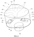
- FIG. 4 is a perspective view of acoustic damper 100.
- Acoustic damper 100 includes at least one wall 104 that cooperates with back side 96 of front panel 90 to define a dampening chamber 106.
- acoustic damper 100 also includes a top 108.
- Wall 104, top 108, and back side 96 of front panel 90 cooperate to define dampening chamber 106.
- Wall 104, top 108, and back side 90 are shown as transparent in FIG. 4 .
- wall 104 in generally elliptical and extends substantially perpendicularly from back side 96.
- wall 104 includes two semicircular arcs 110 and two straight portions 112 that extend substantially perpendicularly from back side 96.
- Straight portions 112 extend continuously from semicircular arcs 110.
- Top 108 includes two half cones 114 on semicircular arcs 110 and two angled portions 116 on straight portions 112. Angled portions 116 are coupled to half cones 114 such that angled portions 116 form an elongated apex 118 defined between half cones 114.
- acoustic damper 100 and dampening chamber 106 may have any other shape that enables acoustic damper 100 to function as described herein.
- the shape of acoustic damper 100 and dampening chamber 106 may be determined by computation fluid dynamic (CFD) analysis and may be selected based on the fuel-to-air stoichiometry within burner 24, the total mass flow within burner 24, and/or any other operating condition.
- CFD computation fluid dynamic
- outlet 102 extends through front panel 90 from front side 94 to back side 96.
- Outlet 102 enables the acoustic pressure oscillations to enter dampening chamber 106 wherein the acoustic pressure oscillations are dampened.
- outlet 102 is a circular conduit extending through front panel 90.
- outlet 102 may have any other shape that that enables acoustic damper 100 to function as described herein.
- the shape of outlet 102 a may be determined by CFD analysis and may be selected based on the fuel-to-air stoichiometry within burner 24, the total mass flow within burner 24, and/or any other operating condition.
- acoustic damper 100 may include any number of outlets 102 that enables acoustic damper 100 to operate as described herein, including, without limitation, two, three, or more outlets 102.
- the number of outlets 102 included with each acoustic damper 100 may be determined by CFD analysis and may be selected based on the fuel-to-air stoichiometry within burner 24, the total mass flow within burner 24, and/or any other operating condition.
- Back side 96 of front panel 90 defines at least one cooling air inlet 120 and/or 122.
- back side 96 of front panel 90 defines a first cooling air inlet 120 and a second cooling air inlet 122.
- cooling air inlets 120 and 122 are oriented to channel a flow of cooling air, as indicated by arrows 124 and 126, into dampening chamber 106.
- first cooling air inlet 120 is oriented to channel a first flow of cooling air, as indicated by arrow 124
- second cooling air inlet 122 is oriented to channel a second flow of cooling air, as indicated by arrow 126.
- acoustic damper 100 may include any other number of cooling air inlets 120 and 122 that enables acoustic damper 100 to function as described herein, including, without limitation, one, three, or more cooling air inlets 120 and 122.
- the number of cooling air inlets 120 and 122 included with each acoustic damper 100 may be determined by CFD analysis and may be selected based on the fuel-to-air stoichiometry within burner 24, the total mass flow within burner 24, and/or any other operating condition.
- the source of flow of cooling air 124 and 126 is compressor section 14, and flow of cooling air 124 and 126 typically has a higher pressure than the combustion gases, such that flow of cooling air 124 and 126 is channeled out of acoustic damper 100 through outlet 102.
- cooling air inlets 120 and 122 are oriented to channel flow of cooling air 124 and 126 into dampening chamber 106, and outlet 102 is oriented to channel flow of cooling air 124 and 126 from dampening chamber 106.
- burner 24 ignites the fuel-air mixture and generates high temperature combustion gases that are channeled towards turbine section 18. Heat released during combustion combined with the increased pressure caused by combustion may cause acoustic pressure oscillations to develop within burner 24.
- the acoustic pressure oscillations enter acoustic damper 100 through outlet 102 and are dampened within dampening chamber 106. Heat released during combustion may damage acoustic damper 100, and cooling air inlets 120 and 122 channel cooling air 124 and 126 into acoustic damper 100 to reduce a temperature of acoustic damper 100 and to facilitate reducing damage caused by the heat released during combustion.
- a high velocity of flow of cooling air 124 and 126 within dampening chamber 106 may reduce a pressure within dampening chamber 106, thus enabling hot combustion gases to be drawn into the dampening chamber 106.
- the hot gases may cause damage to acoustic damper 100.
- At least one cap 128 and/or 130 is positioned within dampening chamber 106 partially over cooling air inlets 120 and 122.
- a plurality of caps 128 and 130 are positioned within dampening chamber 106 such that caps 128 and 130 extend at least partially across cooling air inlets 120 and 122.
- a first cap 128 partially covers first cooling air inlet 120
- a second cap 130 partially covers second cooling air inlet 122.
- Each cap 128 and 130 is positioned within the path of flow of cooling air 124 and 126 to disrupt flow of cooling air 124 and 126 within dampening chamber 106 and to reduce the velocity of flow of cooling air 124 and 126 within dampening chamber 106. As such, caps 128 and 130 facilitate reducing the ingestion of combustion gasses into dampening chamber 106 and reduce damage to acoustic damper 100 caused by the ingestion of combustion gases.
- FIG. 5 is a perspective view of first cap 128 within acoustic damper 100. Wall 104, top 108, and back side 90 are shown as transparent in FIG. 5 .
- FIG. 6 is a cutaway top view of first cap 128.
- caps 128 and 130 are hollow, semispherical coverings or cups that extend from back side 96 and substantially cover cooling air inlets 120 and 122.
- each cap 128 and 130 has a semispherical shell 132 that defines a cap opening 134.
- Shell 132 is positioned within the path of flow of cooling air 124 and 126 to disrupt flow of cooling air 124 and 126 within dampening chamber 106 and to facilitate reducing the velocity of flow of cooling air 124 and 126 within dampening chamber 106. Specifically, shell 132 is positioned over cooling air inlets 120 and 122 such that cap opening 134 faces away from outlet 102.
- Cap opening 134 is oriented to channel flow of cooling air 124 and 126 into dampening chamber 106. Additionally, cooling air inlets 120 and 122 are oriented to channel flow of cooling air 124 and 126 into a back of shell 132 such that flow of cooling air 124 and 126 has to turn in order to exit cap opening 134. Moreover, because cap opening 134 is oriented away from outlet 102, cooling air 124 and 126 has to turn again in order to exit acoustic damper 100 through outlet 102. As such, caps 128 and 130 are positioned over cooling air inlets 120 and 122 to force flow of cooling air 124 and 126 to follow a tortuous path within dampening chamber 106.
- caps 128 and 130 disrupt flow of cooling air 124 and 126 within dampening chamber 106 and reduce the velocity of flow of cooling air 124 and 126 within dampening chamber 106.
- caps 128 and 130 facilitate reducing the ingestion of combustion gasses into dampening chamber 106 and facilitate reducing damage to acoustic damper 100 caused by the ingestion of combustion gases.
- shell 132 has a semi-spherical shape.
- shell 132 may have any other shape that enables acoustic damper 100 to function as described herein including, without limitation, cylindrical and/or parallelepipedal shapes.
- the shape of each shell 132 may be determined by CFD analysis and may be changed based on the fuel-to-air stoichiometry within burner 24, the total mass flow within burner 24, and/or any other operating condition.
- caps 128 and 130 may each have the same shape or caps 128 and 130 may each have a different shape.
- each cap 128 and 130 has a cap diameter 136 and a cut distance 138 that extends substantially perpendicularly from cap diameter 136 to cap opening 134.
- Cut distance 138 determines the size of cap opening 134. Increasing cut distance 138 moves cap opening 134 away from a center 140 of cap 128 and 130 and reduces the size of cap opening 134. Conversely, decreasing cut distance 138 moves cap opening 134 toward center 140 of cap 128 and 130 and increases the size of cap opening 134.
- cap diameter 136 is about 4 millimeters (mm) to about 10 mm. More specifically, in the exemplary embodiment, cap diameter 136 is about 6 mm.
- cut distance 138 is between about 0.5 mm to about 5 mm. More specifically, in the exemplary embodiment, cut distance 138 is about 1.2 mm.
- Cap diameter 136 and cut distance 138 are determined by CFD analysis such that caps 128 and 130 disrupt flow of cooling air 124 and 126 within dampening chamber 106 and reduce the velocity of flow of cooling air 124 and 126 within dampening chamber 106.
- caps 128 and 130 may have any cap diameter 136 and/or cut distance 138 that enables acoustic damper 100 to operate as described herein.
- caps 128 and 130 may each have the same cap diameter 136 and/or cut distance 138, or caps 128 and 130 may each have different cap diameter 136 and cut distance 138.
- acoustic damper 100 includes two caps 128 and 130, one for each cooling air inlets 120 and 122.
- acoustic damper 100 may include any number of caps 128 and 130 that enables acoustic damper 100 to operate as described herein, including, without limitation, one, three, or more caps 128 and 130.
- first cap 128 may be positioned over first cooling air inlet 120, but second cooling air inlet 122 may not be covered by second cap 130.
- the number of caps 128 and 130 may be determined by a CFD analysis which determines the number of caps 128 and 130 required to facilitate reducing ingestion of hot combustion gases into acoustic damper 100.
- each cap 128 and 130 has a position within acoustic damper 100 relative to wall 104. Specifically, each cap 128 and 130 is positioned a cap distance 142 from wall 104. Cap distance 142 is a distance from a center 144 of cap opening 134 to wall 104. Cap distance 142 determines an amount of space between cap 128 and 130 and wall 104 and determines the amount of space flow of cooling air 124 and 126 has to turn toward outlet 102.
- cap distance 142 increases the amount of space that cooling air 124 and 126 has to turn towards outlet 102 and decreases resistance to flow of cooling air 124 and 126 which increases a velocity of flow of cooling air 124 and 126. Conversely, decreasing cap distance 142 decreases an amount of space that cooling air 124 and 126 has to turn towards outlet 102 and increases the resistance to flow of cooling air 124 and 126 which decreases the velocity of flow of cooling air 124 and 126.
- cap distance 142 is about 0.5 mm to about 10 mm. More specifically, in the exemplary embodiment, cap distance 142 is about 1 mm.
- a CFD analysis determines the position of each cap 128 and 130 by adjusting cap distance 142 to disrupt flow of cooling air 124 and 126 within dampening chamber 106 and reduce the velocity of flow of cooling air 124 and 126 within dampening chamber 106. Additionally, the CFD analysis also simultaneously adjusts cap diameter 136 and cut distance 138 for each cap 128 and 130 to disrupt flow of cooling air 124 and 126 within dampening chamber 106 and reduce the velocity of flow of cooling air 124 and 126 within dampening chamber 106. Moreover, in alternative embodiments, shell 132 may be positioned over cooling air inlets 120 and 122 such that cap opening 134 is positioned in any orientation relative to outlet 102 that enables caps 128 and 130 to operate as described herein.
- Cap diameter 136, cut distance 138, and cap distance 142 are adjusted for each cap 128 and 130 to disrupt flow of cooling air 124 and 126 within dampening chamber 106 and to reduce the velocity of flow of cooling air 124 and 126 within dampening chamber 106 in order to reduce ingestion of hot combustion gases into dampening chamber 106 and to reduce damage to acoustic damper 100.
- a CFD analysis adjusts cap diameter 136, cut distance 138, and cap distance 142 such that ingestion of hot combustion gases is reduced. Accordingly, caps 128 and 130 facilitate reducing ingestion of hot combustion gases into acoustic damper 100, reduce damage to acoustic damper 100, and improve the reliability of burner 24 and rotary machine 10.
- FIG. 7 is perspective view of a cap 700.
- FIG. 8 is perspective view of a cap 800.
- Caps 700 and 800 are alternative embodiments of caps 128 and 130.
- Cap opening 134 of cap 700 includes a plurality of cap holes 702 rather than cap opening 134 described above and cap opening 134 of cap 800 includes a plurality of cap holes 802 rather than cap opening 134 described above.
- Cap holes 702 are configured to channel flow of cooling air 124 and 126 out of shell 132 and into dampening chamber 106.
- cap holes 702 are circular holes extending through shell 132.
- cap holes 702 may have any shape that enables cap 700 to operate as described herein.
- cap 700 includes three cap holes 702 arranged linearly.
- cap 700 may include any number of cap holes 702 in any arrangement that enables cap 700 to operate as described herein.
- Cap holes 702 reduce the area that flow of cooling air 124 and 126 has to flow out of shell 132 as compared to cap opening 134 and increases resistance to flow of cooling air 124 and 126 which decreases the velocity of flow of cooling air 124 and 126. Accordingly, cap 700 further decreases the velocity of flow of cooling air 124 and 126 as compared to caps 128 and 130.
- Cap 800 is similar to cap 700 except that cap 800 includes more cap holes 802 arranged linearly in two rows. Cap holes 802 are also larger than cap holes 702. As such, cap holes 802 reduce the area that flow of cooling air 124 and 126 has to flow out of shell 132 as compared to cap opening 134, but cap holes 802 increase the area that flow of cooling air 124 and 126 has to flow out of shell 132 as compared to cap holes 702. Accordingly, cap 800 decreases the velocity of flow of cooling air 124 and 126 as compared to caps 128 and 130 and increases the velocity of flow of cooling air 124 and 126 as compared to cap 700. The velocity of flow of cooling air 124 and 126 may be tuned by adjusting cap opening 134 of caps 128 and 130, 700, and 800.
- cap opening 134 of first cap 128 may include cap holes 702 while cap opening 134 of second cap 130 may include cap opening 134 described above.
- cap opening 134 of caps 128 and 130, 700, and 800 may be adjusted to disrupt flow of cooling air 124 and 126 within dampening chamber 106 and reduce the velocity of flow of cooling air 124 and 126 within dampening chamber 106 in order to reduce ingestion of hot combustion gases into dampening chamber 106 and reduce damage to acoustic damper 100.
- FIG. 9 is a flow diagram of an exemplary method 900 of manufacturing acoustic damper 100.
- the method 900 includes defining 902 at least one outlet 102 to extend through front panel 90. Outlets 102 extend from front side 94 of front panel 90 to back side 96 of front panel 90.
- Method 900 also includes defining 904 at least one cooling air inlets 120 and 122 within back side 96 of front panel 90.
- Method 900 further includes forming 906 at least one wall 104 on back side 96 of front panel 90. Wall 104 and back side 96 of front panel 90 define dampening chamber 106.
- Method 900 also includes forming 908 at least one cap 128 on back side 96 of front panel 90. Cap 128 is oriented to reduce the velocity of flow of cooling air 124 and 126 within dampening chamber 106.
- Acoustic dampers 100 described herein may be manufactured using any manufacturing technique that enables acoustic damper 100 to operate as described herein.
- each acoustic damper 100 is manufactured by additively manufacturing acoustic damper 100 and front panel 90.
- front panel 90 is additively manufactured to define outlets 102 and cooling air inlets 120 and 122 within front panel 90.
- Acoustic dampers 100 and caps 128 are then additively manufactured on back side 96 of front panel 90. Additively manufacturing reduces the cost and time to form caps 128 within acoustic dampers 100.
- additively manufacturing acoustic damper 100 facilitates reducing the cost and manufacturing time to produce acoustic dampers 100 with caps 128 while increasing the reliability of burner 24 and rotary machine 10.
- the exemplary acoustic dampers and methods described herein facilitate reducing a velocity of a cooling stream within the acoustic dampers, reducing acoustic oscillations within a burner, and reducing the ingestion of hot gas into the acoustic damper.
- the exemplary acoustic dampers described herein include at least one wall extending from a back side of a front panel of a burner. The wall and the back side of the front panel define a dampening chamber. The back side of the front panel also defines at least one cooling air inlet and at least one outlet. The cooling air inlet is oriented to channel a flow of cooling air into the dampening chamber, and the outlet is oriented to channel the flow of cooling air from the dampening chamber.
- the damper further includes at least one cap within a flow path of the cooling air and that extends from the back side of the front panel and over the cooling air inlet.
- the outlet of the acoustic damper enables passage of acoustic oscillations into the acoustic damper, thus dampening the acoustic pressure oscillations, and reducing damage to the burner.
- the flow of cooling air into the dampening chamber cools the acoustic damper and facilitates reducing damage to the acoustic damper.
- a velocity of the flow of cooling air within the dampening chamber reduces a pressure within the dampening chamber. The reduced pressure may enable hot combustion gases to be ingested or channeled into dampening chamber, potentially causing damage to the acoustic damage.
- the cap facilitates reducing the velocity of the flow of cooling air and reducing potential damage to the acoustic damper caused by ingestion of combustion gases.
Landscapes
- Engineering & Computer Science (AREA)
- Chemical & Material Sciences (AREA)
- Combustion & Propulsion (AREA)
- Mechanical Engineering (AREA)
- General Engineering & Computer Science (AREA)
- Soundproofing, Sound Blocking, And Sound Damping (AREA)
- Structures Of Non-Positive Displacement Pumps (AREA)
- Gas Burners (AREA)
Abstract
Description
- The field of the disclosure relates generally to gas turbine engines, and more particularly to a high frequency dampers used within gas turbine engines.
- Gas turbine engines typically include at least one compressor, at least one burner, and at least one turbine arranged in a serial flow configuration. Typically, the compressor channels compressed air to the burner where it is mixed with a flow of fuel and combusted, creating a high temperature flow of combustion gas that is channeled to the turbine. However, combustion within at least some burners may be unstable because the combustion dynamics within the burner may be unstable. Specifically, heat released during combustion, combined with the increased pressure caused by combustion, may cause acoustic pressure oscillations to develop within the burner.
- Within known burners, the acoustic pressure oscillations typically occur during normal operating conditions and may depend on a fuel-to-air stoichiometry within the burner, a total mass flow within the burner, and/or other operating conditions. Over time, the acoustic pressure oscillations may cause equipment damage or other operational problems. To facilitate reducing the effect of the acoustic pressure oscillations, at least some burners include at least one acoustic damper that absorbs the acoustic pressure oscillations and that reduces the amplitude of the pressure oscillations. To prevent damage to the acoustic damper and to keep the acoustic damper clean, a flow of compressed cooling air is channeled into the acoustic damper. However, if the flow of compressed cooling air enters the acoustic damper at a high velocity, the pressure within the acoustic damper may decrease, allowing hot combustion gases to flow into the acoustic damper. In contrast, if the flow of cooling air is at a low velocity, cooling may be ineffective within the acoustic damper.
- In one aspect, an acoustic damper for a rotary machine is provided. The rotary machine includes at least one burner including a front panel having a front side and an opposing back side. The acoustic damper includes at least one wall, at least one cooling air inlet, at least one outlet, and at least one cap. The at least one wall extends from the back side of the front panel and defines a dampening chamber. The at least one cooling air inlet is defined within the back side of the front panel and is configured to channel a flow of cooling air into the dampening chamber. The at least one outlet is defined within the back side of the front panel and is configured to channel the flow of cooling air out of the dampening chamber. The at least one cap is positioned at least partially over the at least one cooling air inlet and is configured to reduce a velocity of the flow of cooling air within the dampening chamber.
- In another aspect, a method of manufacturing an acoustic damper on a front panel of a burner is provided. The method includes defining an outlet through the front panel. The outlet extends from a front side of the front panel to a back side of the front panel. The method also includes defining at least one cooling air inlet within the back side of the front panel. The method further includes forming at least one wall on the back side of the front panel. The at least one wall and the back side of the front panel defining a dampening chamber. The method also includes forming at least one cap positioned at least partially over the at least one cooling air inlet. The at least one cap is configured to reduce a velocity of a flow of cooling air within the dampening chamber.
- In another aspect, a rotary machine is provided. The rotary machine includes at least one burner and at least one acoustic damper. The at least one burner includes a front panel having a front side and an opposing back side. The at least one acoustic damper is positioned on the back side of the front panel and includes at least one wall, at least one cooling air inlet, at least one outlet, and at least one cap. The at least one wall extends from the back side of the front panel and defines a dampening chamber. The at least one cooling air inlet is defined within the back side of the front panel and is configured to channel a flow of cooling air into the dampening chamber. The at least one outlet is defined within the back side of the front panel and is configured to channel the flow of cooling air out of the dampening chamber. The at least one cap positioned at least partially over the at least one cooling air inlet and configured to reduce a velocity of the flow of cooling air within the dampening chamber.
-
-
FIG. 1 is a schematic diagram of an exemplary rotary machine; -
FIG. 2 is a perspective view of an exemplary burner positioned with a combustor section of the rotary machine shown inFIG. 1 ; -
FIG. 3 is a rear view of an exemplary front panel that may be positioned within the burner shown inFIG. 2 ; -
FIG. 4 is a perspective view of an exemplary acoustic damper that may be positioned on a back side of the front panel shown inFIG. 3 ; -
FIG. 5 is a perspective of an exemplary cap used with the acoustic damper shown inFIG. 4 ; -
FIG. 6 is a cutaway top view of the cap shown inFIG. 4 ; -
FIG. 7 is perspective view of an alternative cap that may be used with the acoustic damper shown inFIG. 4 ; -
FIG. 8 is perspective view of another alternative cap that may be used with the acoustic damper shown inFIG. 4 ; and -
FIG. 9 is a flow diagram of an exemplary method of manufacturing an acoustic damper, such as the acoustic damper shown inFIG. 4 . - The exemplary acoustic dampers and methods described herein facilitate reducing a velocity of a cooling stream within the acoustic dampers, reducing acoustic oscillations within a burner, and reducing the ingestion of hot gas into the acoustic damper. The exemplary acoustic dampers described herein include at least one wall extending from a back side of a front panel of a burner. The wall and the back side of the front panel define a dampening chamber. The back side of the front panel also defines at least one cooling air inlet and at least one outlet. The cooling air inlet is oriented to channel a flow of cooling air into the dampening chamber, and the outlet is oriented to channel the flow of cooling air from the dampening chamber. The damper further includes at least one cap within a flow path of the cooling air and that extends from the back side of the front panel and over the cooling air inlet.
- During operation, the outlet of the acoustic damper enables passage of acoustic oscillations into the acoustic damper, thus dampening the acoustic pressure oscillations, and reducing damage to the burner. The flow of cooling air into the dampening chamber cools the acoustic damper and facilitates reducing damage to the acoustic damper. A velocity of the flow of cooling air within the dampening chamber reduces a pressure within the dampening chamber. The reduced pressure may enable hot combustion gases to be ingested or channeled into dampening chamber, potentially causing damage to the acoustic damage. The cap facilitates reducing the velocity of the flow of cooling air and reducing potential damage to the acoustic damper caused by ingestion of combustion gases.
- Unless otherwise indicated, approximating language, such as "generally," "substantially," and "about," as used herein indicates that the term so modified may apply to only an approximate degree, as would be recognized by one of ordinary skill in the art, rather than to an absolute or perfect degree. Approximating language may be applied to modify any quantitative representation that could permissibly vary without resulting in a change in the basic function to which it is related. Accordingly, a value modified by a term or terms, such as "about," "approximately," and "substantially," are not to be limited to the precise value specified. In at least some instances, the approximating language may correspond to the precision of an instrument for measuring the value. Here and throughout the specification and claims, range limitations may be identified. Such ranges may be combined and/or interchanged, and include all the sub-ranges contained therein unless context or language indicates otherwise.
- Additionally, unless otherwise indicated, the terms "first," "second," etc. are used herein merely as labels, and are not intended to impose ordinal, positional, or hierarchical requirements on the items to which these terms refer. Moreover, reference to, for example, a "second" item does not require or preclude the existence of, for example, a "first" or lower-numbered item or a "third" or higher-numbered item.
-
FIG. 1 is a schematic view of an exemplaryrotary machine 10 with which embodiments of the current disclosure may be used. In the exemplary embodiment,rotary machine 10 is a gas turbine that includes anintake section 12, acompressor section 14 coupled downstream fromintake section 12, acombustor section 16 coupled downstream fromcompressor section 14, aturbine section 18 coupled downstream fromcombustor section 16, and anexhaust section 20 coupled downstream fromturbine section 18. A generallytubular casing 36 at least partially encloses one or more ofintake section 12,compressor section 14,combustor section 16,turbine section 18, andexhaust section 20. In alternative embodiments,rotary machine 10 is any machine having rotor blades for which the embodiments of the current disclosure are enabled to function as described herein. In the exemplary embodiment,turbine section 18 is coupled tocompressor section 14 via arotor shaft 22. It should be noted that, as used herein, the term "couple" is not limited to a direct mechanical, electrical, and/or communication connection between components, but may also include an indirect mechanical, electrical, and/or communication connection between multiple components. - During operation of
gas turbine 10,intake section 12 channels air towardscompressor section 14.Compressor section 14 compresses the air to a higher pressure and temperature. More specifically,rotor shaft 22 imparts rotational energy to at least one circumferential row ofcompressor blades 40 coupled torotor shaft 22 withincompressor section 14. In the exemplary embodiment, each row ofcompressor blades 40 is preceded by a circumferential row ofcompressor stator vanes 42 extending radially inward from casing 36 that direct the air flow intocompressor blades 40. The rotational energy ofcompressor blades 40 increases a pressure and temperature of the air.Compressor section 14 discharges the compressed air towardscombustor section 16. - In
combustor section 16, compressed air is mixed with fuel and ignited to generate combustion gases that are channeled towardsturbine section 18. More specifically,combustor section 16 includes at least oneburner 24, in which a fuel, for example, natural gas and/or fuel oil, is injected into the air flow, and the fuel-air mixture is ignited to generate high temperature combustion gases that are channeled towardsturbine section 18. -
Turbine section 18 converts thermal energy from the combustion gas stream to mechanical rotational energy. More specifically, the combustion gases impart rotational energy to at least one circumferential row ofrotor blades 70 coupled torotor shaft 22 withinturbine section 18. In the exemplary embodiment, each row ofrotor blades 70 is preceded by a circumferential row ofturbine stator vanes 72 extending radially inward from casing 36 that direct the combustion gases intorotor blades 70.Rotor shaft 22 may be coupled to a load (not shown) such as, but not limited to, an electrical generator and/or a mechanical drive application. The exhausted combustion gases flow downstream fromturbine section 18 intoexhaust section 20. -
FIG. 2 is a perspective view ofburner 24 positioned withcombustor section 16 and including an exemplaryfront panel 90.FIG. 3 is a rear view offront panel 90 positioned withinburner 24.Burner 24 includes at least oneburner wall 80 that defines aburner chamber 82, aburner inlet 84, and aburner outlet 86.Front panel 90 is coupled toburner inlet 84 and defines afront panel inlet 92.Front panel 90 has afront side 94 and aback side 96 that is oppositefront side 94.Front panel 90 is positioned onburner 24 such that backside 96 is coupled toburner 24, andfront side 94 is oriented away fromburner 24. As shown inFIG. 3 , a plurality ofacoustic dampers 100 extend across onback side 96 offront panel 90. In the exemplary embodiment, about thirty to about fortyacoustic dampers 100 are positioned onback side 96 offront panel 90. However, any number ofacoustic dampers 100 that enableburner 24 to operate as described herein may be positioned onback side 96 offront panel 90.Front panel 90 defines a plurality ofoutlets 102 that extend throughfront panel 90 fromfront side 94 to backside 96. - During operations, the flow of compressed air from
compressor section 14 is channeled intoburner 24 throughfront panel inlet 92 andburner inlet 84. A flow of fuel is injected into the flow of compressed air and the mixture of compressed air and fuel is ignited. Combustion withinburner 24 may be unstable because the combustion dynamics withinburner 24 may be unstable. Specifically, heat released during combustion, combined with the increased pressure caused by combustion, may cause acoustic pressure oscillations withinburner 24. Acoustic pressure oscillations generally occur during normal operating conditions and may depend on a fuel-to-air stoichiometry withinburner 24, a total mass flow withinburner 24, and/or other operating conditions. The acoustic pressure oscillations may cause equipment damage or other operational problems. However,acoustic dampers 100 facilitate absorbing the acoustic pressure oscillations and/or reducing the amplitude of the pressure oscillations. Specifically,outlets 102 enable the acoustic pressure oscillations to enteracoustic dampers 100 where the acoustic pressure oscillations are dampened. -
FIG. 4 is a perspective view ofacoustic damper 100.Acoustic damper 100 includes at least onewall 104 that cooperates withback side 96 offront panel 90 to define a dampeningchamber 106. In the exemplary embodiment,acoustic damper 100 also includes a top 108.Wall 104, top 108, and backside 96 offront panel 90 cooperate to define dampeningchamber 106.Wall 104, top 108, and backside 90 are shown as transparent inFIG. 4 . - In the illustrated embodiment,
wall 104 in generally elliptical and extends substantially perpendicularly from backside 96. Specifically, in the illustrated embodiment,wall 104 includes twosemicircular arcs 110 and twostraight portions 112 that extend substantially perpendicularly from backside 96.Straight portions 112 extend continuously fromsemicircular arcs 110.Top 108 includes twohalf cones 114 onsemicircular arcs 110 and twoangled portions 116 onstraight portions 112.Angled portions 116 are coupled tohalf cones 114 such thatangled portions 116 form anelongated apex 118 defined betweenhalf cones 114. In the illustrated embodiment,semicircular arcs 110,straight portions 112,half cones 114,angled portions 116,elongated apex 118, and backside 96 offront panel 90 cooperate to define dampeningchamber 106. Alternatively,acoustic damper 100 and dampeningchamber 106 may have any other shape that enablesacoustic damper 100 to function as described herein. Specifically, the shape ofacoustic damper 100 and dampeningchamber 106 may be determined by computation fluid dynamic (CFD) analysis and may be selected based on the fuel-to-air stoichiometry withinburner 24, the total mass flow withinburner 24, and/or any other operating condition. - As shown in
FIG. 4 , at least oneoutlet 102 extends throughfront panel 90 fromfront side 94 to backside 96.Outlet 102 enables the acoustic pressure oscillations to enter dampeningchamber 106 wherein the acoustic pressure oscillations are dampened. In the exemplary embodiment,outlet 102 is a circular conduit extending throughfront panel 90. Alternatively,outlet 102 may have any other shape that that enablesacoustic damper 100 to function as described herein. Specifically, the shape of outlet 102 a may be determined by CFD analysis and may be selected based on the fuel-to-air stoichiometry withinburner 24, the total mass flow withinburner 24, and/or any other operating condition. Additionally, although the exemplary embodiment only includes asingle outlet 102 for eachacoustic damper 100,acoustic damper 100 may include any number ofoutlets 102 that enablesacoustic damper 100 to operate as described herein, including, without limitation, two, three, ormore outlets 102. Specifically, the number ofoutlets 102 included with eachacoustic damper 100 may be determined by CFD analysis and may be selected based on the fuel-to-air stoichiometry withinburner 24, the total mass flow withinburner 24, and/or any other operating condition. - Back
side 96 offront panel 90 defines at least one coolingair inlet 120 and/or 122. Specifically, in the exemplary embodiment, backside 96 offront panel 90 defines a firstcooling air inlet 120 and a secondcooling air inlet 122. coolingair inlets arrows chamber 106. Specifically, first coolingair inlet 120 is oriented to channel a first flow of cooling air, as indicated byarrow 124, and secondcooling air inlet 122 is oriented to channel a second flow of cooling air, as indicated byarrow 126. However,acoustic damper 100 may include any other number ofcooling air inlets acoustic damper 100 to function as described herein, including, without limitation, one, three, or morecooling air inlets cooling air inlets acoustic damper 100 may be determined by CFD analysis and may be selected based on the fuel-to-air stoichiometry withinburner 24, the total mass flow withinburner 24, and/or any other operating condition. In the exemplary embodiment, the source of flow of coolingair compressor section 14, and flow of coolingair air acoustic damper 100 throughoutlet 102. As such,cooling air inlets air chamber 106, andoutlet 102 is oriented to channel flow of coolingair chamber 106. - During operations,
burner 24 ignites the fuel-air mixture and generates high temperature combustion gases that are channeled towardsturbine section 18. Heat released during combustion combined with the increased pressure caused by combustion may cause acoustic pressure oscillations to develop withinburner 24. The acoustic pressure oscillations enteracoustic damper 100 throughoutlet 102 and are dampened within dampeningchamber 106. Heat released during combustion may damageacoustic damper 100, and coolingair inlets channel cooling air acoustic damper 100 to reduce a temperature ofacoustic damper 100 and to facilitate reducing damage caused by the heat released during combustion. However, a high velocity of flow of coolingair chamber 106 may reduce a pressure within dampeningchamber 106, thus enabling hot combustion gases to be drawn into the dampeningchamber 106. The hot gases may cause damage toacoustic damper 100. - To reduce the velocity of flow of cooling
air chamber 106, at least onecap 128 and/or 130 is positioned within dampeningchamber 106 partially over coolingair inlets caps chamber 106 such that caps 128 and 130 extend at least partially across coolingair inlets first cap 128 partially covers first coolingair inlet 120, and asecond cap 130 partially covers second coolingair inlet 122. Eachcap air air chamber 106 and to reduce the velocity of flow of coolingair chamber 106. As such, caps 128 and 130 facilitate reducing the ingestion of combustion gasses into dampeningchamber 106 and reduce damage toacoustic damper 100 caused by the ingestion of combustion gases. -
FIG. 5 is a perspective view offirst cap 128 withinacoustic damper 100.Wall 104, top 108, and backside 90 are shown as transparent inFIG. 5 .FIG. 6 is a cutaway top view offirst cap 128. In the illustrated embodiment, caps 128 and 130 are hollow, semispherical coverings or cups that extend from backside 96 and substantially cover coolingair inlets cap semispherical shell 132 that defines acap opening 134.Shell 132 is positioned within the path of flow of coolingair air chamber 106 and to facilitate reducing the velocity of flow of coolingair chamber 106. Specifically,shell 132 is positioned over coolingair inlets cap opening 134 faces away fromoutlet 102. -
Cap opening 134 is oriented to channel flow of coolingair chamber 106. Additionally, coolingair inlets air shell 132 such that flow of coolingair cap opening 134. Moreover, becausecap opening 134 is oriented away fromoutlet 102, coolingair acoustic damper 100 throughoutlet 102. As such, caps 128 and 130 are positioned over coolingair inlets air chamber 106. Accordingly, caps 128 and 130 disrupt flow of coolingair chamber 106 and reduce the velocity of flow of coolingair chamber 106. As such, caps 128 and 130 facilitate reducing the ingestion of combustion gasses into dampeningchamber 106 and facilitate reducing damage toacoustic damper 100 caused by the ingestion of combustion gases. - In the illustrated embodiment,
shell 132 has a semi-spherical shape. However,shell 132 may have any other shape that enablesacoustic damper 100 to function as described herein including, without limitation, cylindrical and/or parallelepipedal shapes. Specifically, the shape of eachshell 132 may be determined by CFD analysis and may be changed based on the fuel-to-air stoichiometry withinburner 24, the total mass flow withinburner 24, and/or any other operating condition. Additionally, caps 128 and 130 may each have the same shape or caps 128 and 130 may each have a different shape. - As shown in
FIG. 6 , eachcap cap diameter 136 and acut distance 138 that extends substantially perpendicularly fromcap diameter 136 to capopening 134.Cut distance 138 determines the size ofcap opening 134. Increasingcut distance 138 movescap opening 134 away from acenter 140 ofcap cap opening 134. Conversely, decreasingcut distance 138 movescap opening 134 towardcenter 140 ofcap cap opening 134. In the exemplary embodiment,cap diameter 136 is about 4 millimeters (mm) to about 10 mm. More specifically, in the exemplary embodiment,cap diameter 136 is about 6 mm. In the exemplary embodiment, cutdistance 138 is between about 0.5 mm to about 5 mm. More specifically, in the exemplary embodiment, cutdistance 138 is about 1.2 mm. -
Cap diameter 136 and cutdistance 138 are determined by CFD analysis such thatcaps air chamber 106 and reduce the velocity of flow of coolingair chamber 106. However, caps 128 and 130 may have anycap diameter 136 and/or cutdistance 138 that enablesacoustic damper 100 to operate as described herein. Additionally, caps 128 and 130 may each have thesame cap diameter 136 and/or cutdistance 138, or caps 128 and 130 may each havedifferent cap diameter 136 and cutdistance 138. - In the exemplary embodiment,
acoustic damper 100 includes twocaps air inlets acoustic damper 100 may include any number ofcaps acoustic damper 100 to operate as described herein, including, without limitation, one, three, ormore caps first cap 128 may be positioned over first coolingair inlet 120, but secondcooling air inlet 122 may not be covered bysecond cap 130. The number ofcaps caps acoustic damper 100. Additionally, eachcap acoustic damper 100 relative towall 104. Specifically, eachcap cap distance 142 fromwall 104.Cap distance 142 is a distance from acenter 144 ofcap opening 134 towall 104.Cap distance 142 determines an amount of space betweencap wall 104 and determines the amount of space flow of coolingair outlet 102. - Increasing
cap distance 142 increases the amount of space that coolingair outlet 102 and decreases resistance to flow of coolingair air cap distance 142 decreases an amount of space that coolingair outlet 102 and increases the resistance to flow of coolingair air cap distance 142 is about 0.5 mm to about 10 mm. More specifically, in the exemplary embodiment,cap distance 142 is about 1 mm. A CFD analysis determines the position of eachcap cap distance 142 to disrupt flow of coolingair chamber 106 and reduce the velocity of flow of coolingair chamber 106. Additionally, the CFD analysis also simultaneously adjustscap diameter 136 and cutdistance 138 for eachcap air chamber 106 and reduce the velocity of flow of coolingair chamber 106. Moreover, in alternative embodiments,shell 132 may be positioned over coolingair inlets cap opening 134 is positioned in any orientation relative tooutlet 102 that enablescaps -
Cap diameter 136, cutdistance 138, andcap distance 142 are adjusted for eachcap air chamber 106 and to reduce the velocity of flow of coolingair chamber 106 in order to reduce ingestion of hot combustion gases into dampeningchamber 106 and to reduce damage toacoustic damper 100. Specifically, a CFD analysis adjustscap diameter 136, cutdistance 138, andcap distance 142 such that ingestion of hot combustion gases is reduced. Accordingly, caps 128 and 130 facilitate reducing ingestion of hot combustion gases intoacoustic damper 100, reduce damage toacoustic damper 100, and improve the reliability ofburner 24 androtary machine 10. -
FIG. 7 is perspective view of acap 700.FIG. 8 is perspective view of acap 800.Caps caps Cap opening 134 ofcap 700 includes a plurality of cap holes 702 rather thancap opening 134 described above andcap opening 134 ofcap 800 includes a plurality of cap holes 802 rather thancap opening 134 described above. Cap holes 702 are configured to channel flow of coolingair shell 132 and into dampeningchamber 106. In the illustrated embodiment, cap holes 702 are circular holes extending throughshell 132. However, cap holes 702 may have any shape that enablescap 700 to operate as described herein. In the illustrated embodiment,cap 700 includes threecap holes 702 arranged linearly. However,cap 700 may include any number of cap holes 702 in any arrangement that enablescap 700 to operate as described herein. Cap holes 702 reduce the area that flow of coolingair shell 132 as compared tocap opening 134 and increases resistance to flow of coolingair air cap 700 further decreases the velocity of flow of coolingair caps -
Cap 800 is similar to cap 700 except thatcap 800 includes more cap holes 802 arranged linearly in two rows. Cap holes 802 are also larger than cap holes 702. As such, cap holes 802 reduce the area that flow of coolingair shell 132 as compared tocap opening 134, but cap holes 802 increase the area that flow of coolingair shell 132 as compared to cap holes 702. Accordingly,cap 800 decreases the velocity of flow of coolingair caps air cap 700. The velocity of flow of coolingair cap opening 134 ofcaps cap opening 134 offirst cap 128 may include cap holes 702 whilecap opening 134 ofsecond cap 130 may includecap opening 134 described above. As such,cap opening 134 ofcaps air chamber 106 and reduce the velocity of flow of coolingair chamber 106 in order to reduce ingestion of hot combustion gases into dampeningchamber 106 and reduce damage toacoustic damper 100. -
FIG. 9 is a flow diagram of anexemplary method 900 of manufacturingacoustic damper 100. Themethod 900 includes defining 902 at least oneoutlet 102 to extend throughfront panel 90.Outlets 102 extend fromfront side 94 offront panel 90 to backside 96 offront panel 90.Method 900 also includes defining 904 at least onecooling air inlets side 96 offront panel 90.Method 900 further includes forming 906 at least onewall 104 onback side 96 offront panel 90.Wall 104 and backside 96 offront panel 90 define dampeningchamber 106.Method 900 also includes forming 908 at least onecap 128 onback side 96 offront panel 90.Cap 128 is oriented to reduce the velocity of flow of coolingair chamber 106. -
Acoustic dampers 100 described herein may be manufactured using any manufacturing technique that enablesacoustic damper 100 to operate as described herein. In the exemplary embodiment, eachacoustic damper 100 is manufactured by additively manufacturingacoustic damper 100 andfront panel 90. Specifically,front panel 90 is additively manufactured to defineoutlets 102 and coolingair inlets front panel 90.Acoustic dampers 100 and caps 128 are then additively manufactured onback side 96 offront panel 90. Additively manufacturing reduces the cost and time to formcaps 128 withinacoustic dampers 100. As such, additively manufacturingacoustic damper 100 facilitates reducing the cost and manufacturing time to produceacoustic dampers 100 withcaps 128 while increasing the reliability ofburner 24 androtary machine 10. - The exemplary acoustic dampers and methods described herein facilitate reducing a velocity of a cooling stream within the acoustic dampers, reducing acoustic oscillations within a burner, and reducing the ingestion of hot gas into the acoustic damper. The exemplary acoustic dampers described herein include at least one wall extending from a back side of a front panel of a burner. The wall and the back side of the front panel define a dampening chamber. The back side of the front panel also defines at least one cooling air inlet and at least one outlet. The cooling air inlet is oriented to channel a flow of cooling air into the dampening chamber, and the outlet is oriented to channel the flow of cooling air from the dampening chamber. The damper further includes at least one cap within a flow path of the cooling air and that extends from the back side of the front panel and over the cooling air inlet.
- During operation, the outlet of the acoustic damper enables passage of acoustic oscillations into the acoustic damper, thus dampening the acoustic pressure oscillations, and reducing damage to the burner. The flow of cooling air into the dampening chamber cools the acoustic damper and facilitates reducing damage to the acoustic damper. A velocity of the flow of cooling air within the dampening chamber reduces a pressure within the dampening chamber. The reduced pressure may enable hot combustion gases to be ingested or channeled into dampening chamber, potentially causing damage to the acoustic damage. The cap facilitates reducing the velocity of the flow of cooling air and reducing potential damage to the acoustic damper caused by ingestion of combustion gases.
- The methods, apparatus, and systems described herein are not limited to the specific embodiments described herein. For example, components of each apparatus or system and/or steps of each method may be used and/or practiced independently and separately from other components and/or steps described herein. In addition, each component and/or step may also be used and/or practiced with other assemblies and methods.
- While the disclosure has been described in terms of various specific embodiments, those skilled in the art will recognize that the disclosure can be practiced with modification within the spirit and scope of the claims. Although specific features of various embodiments of the disclosure may be shown in some drawings and not in others, this is for convenience only. Moreover, references to "one embodiment" in the above description are not intended to be interpreted as excluding the existence of additional embodiments that also incorporate the recited features. In accordance with the principles of the disclosure, any feature of a drawing may be referenced and/or claimed in combination with any feature of any other drawing.
Claims (15)
- An acoustic damper (100) for a rotary machine (10), said acoustic damper (100) comprising:at least one wall (104) extending from a back side (96) of a combustion chamber front panel (90), such that said at least one wall (104) at least partially defined a dampening chamber (106);at least one cooling air inlet (120 and 122) defined within the back side (96) of the front panel (90), said at least one cooling air inlet (120 and 122) oriented to channel a flow of cooling air (124) into the dampening chamber (106);at least one outlet (102) defined within the back side (96) of the front panel (90), said at least one outlet (102) oriented to channel the flow of cooling air (124) out of the dampening chamber (106); andat least one cap (128 and 130) extending at least partially over said at least one cooling air inlet (120 and 122) and oriented to reduce a velocity of the flow of cooling air (124) within the dampening chamber (106).
- The acoustic damper (100) of Claim 1, wherein said at least one cooling air inlet (120 and 122) comprises a first cooling air inlet (120) and a second cooling air inlet (122).
- The acoustic damper (100) of Claim 2, wherein said at least one cap (128 and 130) comprises a first cap (128) positioned partially over said first cooling air inlet (120) and a second cap (130) positioned partially over said second cooling air inlet (122).
- The acoustic damper (100) of Claim 1, wherein said at least one cap (128 and 130) defines a cap opening (134) configured to channel the flow of cooling air (124) into said dampening chamber (106).
- The acoustic damper (100) of Claim 4, wherein said at least one cap (128 and 130) is positioned over said at least cooling air inlet (120 and 122) such that said cap opening (134) faces away from said at least one outlet (102).
- The acoustic damper (100) of Claim 1, wherein said at least one cap (128 and 130) comprises at least one semi-spherical shell (132).
- The acoustic damper (100) of Claim 6, wherein at least one semispherical shell (132) defines a cap diameter (136) of about 4 millimeters to about 10 millimeters.
- The acoustic damper (100) of Claim 1, wherein said at least one cap (128 and 130) defines at least one cap hole (702) configured to channel the flow of cooling air (124) into said dampening chamber (106).
- The acoustic damper (100) of Claim 8, wherein said at least one cap hole (702) comprises a plurality of cap holes (702).
- A rotary machine (10) comprising:at least one burner (24) comprising a front panel (90) having a front side and an opposing back side (96); andat least one acoustic damper (100) positioned on said back side (96) of said front panel (90), said at least one acoustic damper (100) comprising:at least one wall (104) extending from said back side (96) of said front panel (90), such that said at least one wall (104) partially defines a dampening chamber (106);at least one cooling air inlet (120 and 122) defined within said back side (96) of said front panel (90), said at least one cooling air inlet (120 and 122) oriented to channel a flow of cooling air (124) into said dampening chamber (106);at least one outlet (102) defined within said back side (96) of said front panel (90), said at least one outlet (102) oriented to channel the flow of cooling air (124) out of said dampening chamber (106); andat least one cap (128 and 130) extending at least partially over said at least one cooling air inlet (120 and 122) and oriented to reduce a velocity of the flow of cooling air (124) within the dampening chamber (106).
- The rotary machine (10) of Claim 10, wherein said at least one cooling air inlet (120 and 122) comprises a first cooling air inlet (120) and a second cooling air inlet (122).
- The rotary machine (10) of Claim 11, wherein said at least one cap (128 and 130) comprises a first cap (128) positioned partially over said first cooling air inlet (120) and a second cap (130) positioned partially over said second cooling air inlet (122).
- The rotary machine (10) of Claim 10, wherein said at least one cap (128 and 130) defines a cap opening (134) configured to channel the flow of cooling air (124) into said dampening chamber (106).
- The rotary machine (10) of Claim 13, wherein said at least one cap (128 and 130) is positioned over said at least cooling air inlet (120 and 122) such that said cap opening (134) faces away from said at least one outlet (102).
- The rotary machine (10) of Claim 10, wherein said at least one cap (128 and 130) comprises at least one semispherical shell (132).
Applications Claiming Priority (1)
| Application Number | Priority Date | Filing Date | Title |
|---|---|---|---|
| US16/418,450 US11156164B2 (en) | 2019-05-21 | 2019-05-21 | System and method for high frequency accoustic dampers with caps |
Publications (2)
| Publication Number | Publication Date |
|---|---|
| EP3742050A1 true EP3742050A1 (en) | 2020-11-25 |
| EP3742050B1 EP3742050B1 (en) | 2023-12-27 |
Family
ID=70802724
Family Applications (1)
| Application Number | Title | Priority Date | Filing Date |
|---|---|---|---|
| EP20175866.1A Active EP3742050B1 (en) | 2019-05-21 | 2020-05-20 | Front panel for a burner of a gas turbine engine with an accoustic damper |
Country Status (4)
| Country | Link |
|---|---|
| US (1) | US11156164B2 (en) |
| EP (1) | EP3742050B1 (en) |
| JP (1) | JP7536502B2 (en) |
| CN (1) | CN214307197U (en) |
Families Citing this family (3)
| Publication number | Priority date | Publication date | Assignee | Title |
|---|---|---|---|---|
| US11174792B2 (en) | 2019-05-21 | 2021-11-16 | General Electric Company | System and method for high frequency acoustic dampers with baffles |
| US11506382B2 (en) | 2019-09-12 | 2022-11-22 | General Electric Company | System and method for acoustic dampers with multiple volumes in a combustion chamber front panel |
| US11371699B2 (en) | 2019-11-12 | 2022-06-28 | General Electric Company | Integrated front panel for a burner |
Citations (5)
| Publication number | Priority date | Publication date | Assignee | Title |
|---|---|---|---|---|
| JP2007132640A (en) * | 2005-11-14 | 2007-05-31 | Mitsubishi Heavy Ind Ltd | Gas turbine combustor |
| US20120198854A1 (en) * | 2011-02-09 | 2012-08-09 | Reinhard Schilp | Resonator system with enhanced combustor liner cooling |
| US20130098063A1 (en) * | 2010-09-30 | 2013-04-25 | Tohoku Electric Power Co., Ltd. | Coolng structure for recovery-type air-cooled gas turbine combustor |
| WO2013144070A1 (en) * | 2012-03-30 | 2013-10-03 | Alstom Technology Ltd | Combustion chamber seal segments equipped with damping devices |
| US20180156460A1 (en) * | 2016-12-02 | 2018-06-07 | General Electric Company | Method and apparatus for gas turbine combustor inner cap and high frequency acoustic dampers |
Family Cites Families (401)
| Publication number | Priority date | Publication date | Assignee | Title |
|---|---|---|---|---|
| US5487275A (en) | 1992-12-11 | 1996-01-30 | General Electric Co. | Tertiary fuel injection system for use in a dry low NOx combustion system |
| US5319931A (en) | 1992-12-30 | 1994-06-14 | General Electric Company | Fuel trim method for a multiple chamber gas turbine combustion system |
| US5361586A (en) | 1993-04-15 | 1994-11-08 | Westinghouse Electric Corporation | Gas turbine ultra low NOx combustor |
| US6220034B1 (en) | 1993-07-07 | 2001-04-24 | R. Jan Mowill | Convectively cooled, single stage, fully premixed controllable fuel/air combustor |
| US5408825A (en) | 1993-12-03 | 1995-04-25 | Westinghouse Electric Corporation | Dual fuel gas turbine combustor |
| US5465570A (en) | 1993-12-22 | 1995-11-14 | United Technologies Corporation | Fuel control system for a staged combustor |
| JP2950720B2 (en) | 1994-02-24 | 1999-09-20 | 株式会社東芝 | Gas turbine combustion device and combustion control method therefor |
| GB9410233D0 (en) | 1994-05-21 | 1994-07-06 | Rolls Royce Plc | A gas turbine engine combustion chamber |
| NO179883C (en) | 1994-10-14 | 1997-01-08 | Ulstein Turbine As | Fuel / air mixing device |
| US5575144A (en) | 1994-11-28 | 1996-11-19 | General Electric Company | System and method for actively controlling pressure pulses in a gas turbine engine combustor |
| US5836164A (en) | 1995-01-30 | 1998-11-17 | Hitachi, Ltd. | Gas turbine combustor |
| DE69625744T2 (en) | 1995-06-05 | 2003-10-16 | Rolls-Royce Corp., Indianapolis | Lean premix burner with low NOx emissions for industrial gas turbines |
| US5791148A (en) | 1995-06-07 | 1998-08-11 | General Electric Company | Liner of a gas turbine engine combustor having trapped vortex cavity |
| US5647215A (en) | 1995-11-07 | 1997-07-15 | Westinghouse Electric Corporation | Gas turbine combustor with turbulence enhanced mixing fuel injectors |
| US5826429A (en) | 1995-12-22 | 1998-10-27 | General Electric Co. | Catalytic combustor with lean direct injection of gas fuel for low emissions combustion and methods of operation |
| US6201029B1 (en) | 1996-02-13 | 2001-03-13 | Marathon Oil Company | Staged combustion of a low heating value fuel gas for driving a gas turbine |
| DE19605736A1 (en) | 1996-02-16 | 1997-08-21 | Gutehoffnungshuette Man | Process for rapid switchover from premix operation to diffusion operation in a combustion chamber of a gas turbine operated with fuel gas |
| DE19614001A1 (en) | 1996-04-09 | 1997-10-16 | Abb Research Ltd | Combustion chamber |
| DE19615910B4 (en) | 1996-04-22 | 2006-09-14 | Alstom | burner arrangement |
| US6047550A (en) | 1996-05-02 | 2000-04-11 | General Electric Co. | Premixing dry low NOx emissions combustor with lean direct injection of gas fuel |
| DE19620874A1 (en) | 1996-05-23 | 1997-11-27 | Bmw Rolls Royce Gmbh | Fuel injection for a staged gas turbine combustor |
| US5927076A (en) | 1996-10-22 | 1999-07-27 | Westinghouse Electric Corporation | Multiple venturi ultra-low nox combustor |
| TW362128B (en) | 1997-09-30 | 1999-06-21 | Westinghouse Electric Corp | Ultra-low NOx combustor |
| US6209309B1 (en) | 1997-12-19 | 2001-04-03 | Hamilton Sundstrand Corporation | Pulse width modulated fuel flow control for an engine |
| EP0931979A1 (en) | 1998-01-23 | 1999-07-28 | DVGW Deutscher Verein des Gas- und Wasserfaches -Technisch-wissenschaftliche Vereinigung- | Method and apparatus for supressing flame and pressure fluctuations in a furnace |
| DE59907940D1 (en) | 1998-03-10 | 2004-01-15 | Siemens Ag | COMBUSTION CHAMBER AND METHOD FOR OPERATING A COMBUSTION CHAMBER |
| GB9813972D0 (en) | 1998-06-30 | 1998-08-26 | Rolls Royce Plc | A combustion chamber |
| EP0976982B1 (en) | 1998-07-27 | 2003-12-03 | ALSTOM (Switzerland) Ltd | Method of operating the combustion chamber of a liquid-fuel gas turbine |
| DE59810033D1 (en) | 1998-09-16 | 2003-12-04 | Alstom Switzerland Ltd | Process for minimizing thermoacoustic vibrations in gas turbine combustors |
| US6311471B1 (en) | 1999-01-08 | 2001-11-06 | General Electric Company | Steam cooled fuel injector for gas turbine |
| GB9915770D0 (en) | 1999-07-07 | 1999-09-08 | Rolls Royce Plc | A combustion chamber |
| EP1079179B1 (en) | 1999-08-21 | 2004-11-24 | Rolls-Royce Deutschland Ltd & Co KG | Process for adapting the operating condition of a gas-turbine staged combustion chamber |
| WO2001018371A1 (en) | 1999-09-07 | 2001-03-15 | Geza Vermes | Ambient pressure gas turbine system |
| AUPQ446299A0 (en) | 1999-12-02 | 2000-01-06 | Collins, Ralph | Micromachines |
| GB9929601D0 (en) | 1999-12-16 | 2000-02-09 | Rolls Royce Plc | A combustion chamber |
| DE10000415A1 (en) | 2000-01-07 | 2001-09-06 | Alstom Power Schweiz Ag Baden | Method and device for suppressing flow vortices within a fluid power machine |
| US6609376B2 (en) | 2000-02-14 | 2003-08-26 | Ulstein Turbine As | Device in a burner for gas turbines |
| US6374594B1 (en) | 2000-07-12 | 2002-04-23 | Power Systems Mfg., Llc | Silo/can-annular low emissions combustor |
| GB0019533D0 (en) | 2000-08-10 | 2000-09-27 | Rolls Royce Plc | A combustion chamber |
| US6389815B1 (en) | 2000-09-08 | 2002-05-21 | General Electric Company | Fuel nozzle assembly for reduced exhaust emissions |
| DE10056124A1 (en) | 2000-11-13 | 2002-05-23 | Alstom Switzerland Ltd | Burner system with staged fuel injection and method of operation |
| DE10058688B4 (en) | 2000-11-25 | 2011-08-11 | Alstom Technology Ltd. | Damper arrangement for the reduction of combustion chamber pulsations |
| GB2387623B (en) | 2000-11-27 | 2004-12-08 | James Maher | Fuel pump metering system |
| US6959536B1 (en) | 2000-11-27 | 2005-11-01 | James Maher | Fuel pump metering system |
| DE10064893A1 (en) | 2000-12-23 | 2002-11-14 | Alstom Switzerland Ltd | Burner with graduated fuel injection |
| DE10104150A1 (en) | 2001-01-30 | 2002-09-05 | Alstom Switzerland Ltd | Burner system and method for its operation |
| DE10108560A1 (en) | 2001-02-22 | 2002-09-05 | Alstom Switzerland Ltd | Method for operating an annular combustion chamber and an associated annular combustion chamber |
| US6535124B1 (en) | 2001-04-03 | 2003-03-18 | Abb Automation Inc. | Method and apparatus for digital analysis and signal conditioning in a turbine generator silo combustor |
| EP1270902B1 (en) | 2001-06-22 | 2009-10-21 | ALSTOM Technology Ltd | Procedure for the start of a gas turbine system |
| US6543231B2 (en) | 2001-07-13 | 2003-04-08 | Pratt & Whitney Canada Corp | Cyclone combustor |
| EP1423645B1 (en) | 2001-09-07 | 2008-10-08 | Alstom Technology Ltd | Damping arrangement for reducing combustion chamber pulsations in a gas turbine system |
| EP1327824A1 (en) | 2001-12-24 | 2003-07-16 | ABB Schweiz AG | Detection and control of gas turbine combustion operation above lean blowout condition |
| EP1476699B1 (en) | 2002-01-16 | 2013-11-13 | Alstom Technology Ltd | Combustion chamber and damper arrangement for reduction of combustion chamber pulsations in a gas turbine plant |
| US6658856B2 (en) | 2002-01-17 | 2003-12-09 | Vericor Power Systems Llc | Hybrid lean premixing catalytic combustion system for gas turbines |
| US6691515B2 (en) | 2002-03-12 | 2004-02-17 | Rolls-Royce Corporation | Dry low combustion system with means for eliminating combustion noise |
| US6966186B2 (en) | 2002-05-01 | 2005-11-22 | Siemens Westinghouse Power Corporation | Non-catalytic combustor for reducing NOx emissions |
| US6735949B1 (en) | 2002-06-11 | 2004-05-18 | General Electric Company | Gas turbine engine combustor can with trapped vortex cavity |
| GB2390150A (en) | 2002-06-26 | 2003-12-31 | Alstom | Reheat combustion system for a gas turbine including an accoustic screen |
| US6742341B2 (en) | 2002-07-16 | 2004-06-01 | Siemens Westinghouse Power Corporation | Automatic combustion control for a gas turbine |
| WO2004010052A1 (en) | 2002-07-19 | 2004-01-29 | Alstom Technology Ltd | Method for controlling the introduction of inert media into a combustion chamber |
| US6758045B2 (en) | 2002-08-30 | 2004-07-06 | General Electric Company | Methods and apparatus for operating gas turbine engines |
| US6962055B2 (en) | 2002-09-27 | 2005-11-08 | United Technologies Corporation | Multi-point staging strategy for low emission and stable combustion |
| GB0305025D0 (en) | 2003-03-05 | 2003-04-09 | Alstom Switzerland Ltd | Method and device for efficient usage of cooling air for acoustic damping of combustion chamber pulsations |
| US6837052B2 (en) | 2003-03-14 | 2005-01-04 | Power Systems Mfg, Llc | Advanced fuel nozzle design with improved premixing |
| GB0323255D0 (en) | 2003-10-04 | 2003-11-05 | Rolls Royce Plc | Method and system for controlling fuel supply in a combustion turbine engine |
| US8397510B2 (en) | 2003-12-16 | 2013-03-19 | Hitachi, Ltd. | Combustor for gas turbine |
| DE10360951A1 (en) | 2003-12-23 | 2005-07-28 | Alstom Technology Ltd | Thermal power plant with sequential combustion and reduced CO2 emissions and method of operating such a plant |
| GB0329626D0 (en) | 2003-12-23 | 2004-01-28 | Goodrich Control Sys Ltd | Fuel system |
| DE102004015186A1 (en) | 2004-03-29 | 2005-10-20 | Alstom Technology Ltd Baden | Gas turbine combustor and associated operating method |
| DE102004015187A1 (en) | 2004-03-29 | 2005-10-20 | Alstom Technology Ltd Baden | Combustion chamber for a gas turbine and associated operating method |
| ES2616873T3 (en) | 2004-03-31 | 2017-06-14 | Ansaldo Energia Ip Uk Limited | Multiple burner arrangement for operating a combustion chamber as well as procedure for operating multiple burner arrangement |
| US7464552B2 (en) | 2004-07-02 | 2008-12-16 | Siemens Energy, Inc. | Acoustically stiffened gas-turbine fuel nozzle |
| DE102004036911A1 (en) | 2004-07-29 | 2006-03-23 | Alstom Technology Ltd | Operating procedure for a combustion plant |
| US7162874B2 (en) | 2004-07-30 | 2007-01-16 | Hija Holding B.V. | Apparatus and method for gas turbine engine fuel/air premixer exit velocity control |
| EP1624252A1 (en) | 2004-08-06 | 2006-02-08 | Siemens Aktiengesellschaft | Burner, Gas Turbine and Method for Operating a Burner |
| WO2006053825A1 (en) | 2004-11-16 | 2006-05-26 | Alstom Technology Ltd | Gas turbine system and associated combustion chamber |
| US20060107667A1 (en) | 2004-11-22 | 2006-05-25 | Haynes Joel M | Trapped vortex combustor cavity manifold for gas turbine engine |
| US7389643B2 (en) | 2005-01-31 | 2008-06-24 | General Electric Company | Inboard radial dump venturi for combustion chamber of a gas turbine |
| US20060218933A1 (en) | 2005-02-10 | 2006-10-05 | Bruno Schuermans | Method for producing a model-based control device |
| US20060283190A1 (en) | 2005-06-16 | 2006-12-21 | Pratt & Whitney Canada Corp. | Engine status detection with external microphone |
| GB0515034D0 (en) | 2005-07-21 | 2005-08-31 | Rolls Royce Plc | Method and system for operating a multi-stage combustor |
| GB2429516B (en) | 2005-08-27 | 2010-12-29 | Siemens Ind Turbomachinery Ltd | An apparatus for modifying the content of a gaseous fuel |
| US7462220B2 (en) | 2005-08-31 | 2008-12-09 | General Electric Company | Methods and systems for detecting filter rupture |
| EP1926936A1 (en) | 2005-09-05 | 2008-06-04 | Siemens Aktiengesellschaft | Burner arrangement for a combustion chamber, associated combustion chamber and method for combusting fuel |
| WO2007033306A2 (en) | 2005-09-13 | 2007-03-22 | Rolls-Royce Corporation, Ltd. | Gas turbine engine combustion systems |
| US20070089427A1 (en) | 2005-10-24 | 2007-04-26 | Thomas Scarinci | Two-branch mixing passage and method to control combustor pulsations |
| US8881531B2 (en) | 2005-12-14 | 2014-11-11 | Rolls-Royce Power Engineering Plc | Gas turbine engine premix injectors |
| WO2007087907A1 (en) | 2006-01-11 | 2007-08-09 | Alstom Technology Ltd | Method for the operation of a firing plant |
| US7413053B2 (en) * | 2006-01-25 | 2008-08-19 | Siemens Power Generation, Inc. | Acoustic resonator with impingement cooling tubes |
| WO2007099046A1 (en) | 2006-02-28 | 2007-09-07 | Siemens Aktiengesellschaft | Gas turbine burner and method of operating a gas turbine burner |
| WO2007113130A1 (en) | 2006-03-30 | 2007-10-11 | Alstom Technology Ltd | Burner arrangement, preferably in a combustion chamber for a gas turbine |
| DE102006015230A1 (en) | 2006-03-30 | 2007-10-18 | Alstom Technology Ltd. | combustion chamber |
| DE102006015529A1 (en) | 2006-03-31 | 2007-10-04 | Alstom Technology Ltd. | Burner system with staged fuel injection |
| US8001761B2 (en) | 2006-05-23 | 2011-08-23 | General Electric Company | Method and apparatus for actively controlling fuel flow to a mixer assembly of a gas turbine engine combustor |
| GB0610800D0 (en) | 2006-06-01 | 2006-07-12 | Rolls Royce Plc | Combustion chamber for a gas turbine engine |
| US10422534B2 (en) | 2006-06-26 | 2019-09-24 | Joseph Michael Teets | Fuel air premix chamber for a gas turbine engine |
| US7631499B2 (en) | 2006-08-03 | 2009-12-15 | Siemens Energy, Inc. | Axially staged combustion system for a gas turbine engine |
| US7788926B2 (en) * | 2006-08-18 | 2010-09-07 | Siemens Energy, Inc. | Resonator device at junction of combustor and combustion chamber |
| FR2906868B1 (en) | 2006-10-06 | 2011-11-18 | Snecma | FUEL INJECTOR FOR GAS TURBINE ENGINE COMBUSTION CHAMBER |
| EP1930569A1 (en) | 2006-11-01 | 2008-06-11 | ALSTOM Technology Ltd | System for controlling a combustion process for a gas turbine |
| RU2426945C2 (en) | 2007-01-02 | 2011-08-20 | Сименс Акциенгезелльшафт | Burner and fuel feed device for gas turbine |
| EP1942303A1 (en) | 2007-01-02 | 2008-07-09 | Siemens Aktiengesellschaft | Burner for a gas turbine and method for controlling fuel supply to a burner |
| WO2008112220A1 (en) | 2007-03-08 | 2008-09-18 | Davidson Instruments Inc. | Apparatus and methods for monitoring combustion dynamics in a gas turbine engine |
| JP4462282B2 (en) | 2007-03-14 | 2010-05-12 | トヨタ自動車株式会社 | Exhaust control device for internal combustion engine |
| EP1970629A1 (en) | 2007-03-15 | 2008-09-17 | Siemens Aktiengesellschaft | Burner fuel staging |
| WO2008129652A1 (en) | 2007-04-06 | 2008-10-30 | Hitachi, Ltd. | Gas turbine power generating apparatus and method of starting the same |
| US7886545B2 (en) | 2007-04-27 | 2011-02-15 | General Electric Company | Methods and systems to facilitate reducing NOx emissions in combustion systems |
| US20090077945A1 (en) | 2007-08-24 | 2009-03-26 | Delavan Inc | Variable amplitude double binary valve system for active fuel control |
| US8387398B2 (en) | 2007-09-14 | 2013-03-05 | Siemens Energy, Inc. | Apparatus and method for controlling the secondary injection of fuel |
| KR101206891B1 (en) | 2007-09-14 | 2012-11-30 | 지멘스 에너지, 인코포레이티드 | Secondary fuel delivery system |
| US7886539B2 (en) | 2007-09-14 | 2011-02-15 | Siemens Energy, Inc. | Multi-stage axial combustion system |
| US7665309B2 (en) | 2007-09-14 | 2010-02-23 | Siemens Energy, Inc. | Secondary fuel delivery system |
| US8122725B2 (en) | 2007-11-01 | 2012-02-28 | General Electric Company | Methods and systems for operating gas turbine engines |
| EP2071156B1 (en) | 2007-12-10 | 2013-11-06 | Alstom Technology Ltd | Fuel distribution system for a gas turbine with multistage burner arrangement |
| JP4831836B2 (en) | 2007-12-13 | 2011-12-07 | 三菱重工業株式会社 | Gas turbine control method and gas turbine power generator |
| JP2009156542A (en) | 2007-12-27 | 2009-07-16 | Mitsubishi Heavy Ind Ltd | Burner for gas turbine |
| JP2009191846A (en) | 2008-02-12 | 2009-08-27 | Delavan Inc | Gas turbine engine combustion stability control method and device |
| EP2257736B1 (en) | 2008-03-07 | 2015-11-25 | Alstom Technology Ltd | Method for the production of hot gas |
| JP4981732B2 (en) | 2008-03-28 | 2012-07-25 | 三菱重工業株式会社 | Exhaust turbine with exhaust control valve |
| EP2107306A1 (en) | 2008-03-31 | 2009-10-07 | Siemens Aktiengesellschaft | A combustor casing |
| EP2107314A1 (en) | 2008-04-01 | 2009-10-07 | Siemens Aktiengesellschaft | Combustor for a gas turbine |
| EP2107311A1 (en) | 2008-04-01 | 2009-10-07 | Siemens Aktiengesellschaft | Size scaling of a burner |
| EP2107309A1 (en) | 2008-04-01 | 2009-10-07 | Siemens Aktiengesellschaft | Quarls in a burner |
| EP2107313A1 (en) | 2008-04-01 | 2009-10-07 | Siemens Aktiengesellschaft | Fuel staging in a burner |
| EP2107310A1 (en) | 2008-04-01 | 2009-10-07 | Siemens Aktiengesellschaft | Burner |
| EP2107227B1 (en) | 2008-04-03 | 2013-07-24 | Alstom Technology Ltd | Control method for a gas turbine plant |
| EP2116766B1 (en) | 2008-05-09 | 2016-01-27 | Alstom Technology Ltd | Burner with fuel lance |
| EP2119964B1 (en) | 2008-05-15 | 2018-10-31 | Ansaldo Energia IP UK Limited | Method for reducing emissons from a combustor |
| EP2119966A1 (en) | 2008-05-15 | 2009-11-18 | ALSTOM Technology Ltd | Combustor with reduced carbon monoxide emissions |
| US8549859B2 (en) | 2008-07-28 | 2013-10-08 | Siemens Energy, Inc. | Combustor apparatus in a gas turbine engine |
| CH699322A1 (en) | 2008-08-14 | 2010-02-15 | Alstom Technology Ltd | METHOD FOR SETTING A Helmholtz resonator AND HELMHOLTZ RESONATOR FOR IMPLEMENTING THE PROCESS. |
| EP2161500A1 (en) | 2008-09-04 | 2010-03-10 | Siemens Aktiengesellschaft | Combustor system and method of reducing combustion instability and/or emissions of a combustor system |
| US8375726B2 (en) | 2008-09-24 | 2013-02-19 | Siemens Energy, Inc. | Combustor assembly in a gas turbine engine |
| US8230688B2 (en) | 2008-09-29 | 2012-07-31 | Siemens Energy, Inc. | Modular transvane assembly |
| US8220269B2 (en) | 2008-09-30 | 2012-07-17 | Alstom Technology Ltd. | Combustor for a gas turbine engine with effusion cooled baffle |
| EP2248999A1 (en) | 2008-12-24 | 2010-11-10 | Alstom Technology Ltd | Power plant with CO2 capture |
| EP2206964A3 (en) | 2009-01-07 | 2012-05-02 | General Electric Company | Late lean injection fuel injector configurations |
| US8707707B2 (en) | 2009-01-07 | 2014-04-29 | General Electric Company | Late lean injection fuel staging configurations |
| US8701382B2 (en) | 2009-01-07 | 2014-04-22 | General Electric Company | Late lean injection with expanded fuel flexibility |
| US8701418B2 (en) | 2009-01-07 | 2014-04-22 | General Electric Company | Late lean injection for fuel flexibility |
| US8683808B2 (en) | 2009-01-07 | 2014-04-01 | General Electric Company | Late lean injection control strategy |
| ES2576651T3 (en) | 2009-01-15 | 2016-07-08 | Alstom Technology Ltd | Burner of a gas turbine |
| US8689559B2 (en) | 2009-03-30 | 2014-04-08 | General Electric Company | Secondary combustion system for reducing the level of emissions generated by a turbomachine |
| US9052114B1 (en) | 2009-04-30 | 2015-06-09 | Majed Toqan | Tangential annular combustor with premixed fuel and air for use on gas turbine engines |
| US9091446B1 (en) | 2009-04-30 | 2015-07-28 | Majed Toqan | Tangential and flameless annular combustor for use on gas turbine engines |
| US8720206B2 (en) | 2009-05-14 | 2014-05-13 | General Electric Company | Methods and systems for inducing combustion dynamics |
| US9890714B2 (en) | 2009-05-26 | 2018-02-13 | Ansaldo Energia Ip Uk Limited | Automated extended turndown of a gas turbine engine combined with incremental tuning to maintain emissions and dynamics |
| US9097185B2 (en) | 2009-05-26 | 2015-08-04 | Alstom Technology Ltd | Stabilizing a gas turbine engine via incremental tuning |
| DE102009032277A1 (en) * | 2009-07-08 | 2011-01-20 | Rolls-Royce Deutschland Ltd & Co Kg | Combustion chamber head of a gas turbine |
| US9228491B2 (en) | 2009-08-04 | 2016-01-05 | Jack R. Taylor | Two-stroke uniflow turbo-compound internal combustion engine |
| US8348645B2 (en) | 2009-08-11 | 2013-01-08 | Woodward, Inc. | Balanced pressure, variable displacement, dual lobe, single ring, vane pump |
| EP2290206B1 (en) | 2009-08-28 | 2015-07-15 | Alstom Technology Ltd | Method for operating a gas turbine plant with reduced NOx emissions |
| KR101678010B1 (en) | 2009-09-10 | 2016-11-21 | 보르그워너 인코퍼레이티드 | Exhaust-gas supply device of a turbine wheel of an exhaust-gas turbocharger |
| JP5663023B2 (en) | 2009-09-13 | 2015-02-04 | リーン フレイム インコーポレイテッド | Inlet premixer for combustion equipment |
| EP2299177A1 (en) | 2009-09-21 | 2011-03-23 | Alstom Technology Ltd | Combustor of a gas turbine |
| US8991192B2 (en) | 2009-09-24 | 2015-03-31 | Siemens Energy, Inc. | Fuel nozzle assembly for use as structural support for a duct structure in a combustor of a gas turbine engine |
| US8375548B2 (en) | 2009-10-07 | 2013-02-19 | Pratt & Whitney Canada Corp. | Fuel nozzle and method of repair |
| WO2011054757A2 (en) | 2009-11-07 | 2011-05-12 | Alstom Technology Ltd | Reheat burner injection system with fuel lances |
| IT1396515B1 (en) | 2009-11-27 | 2012-12-14 | Nuovo Pignone Spa | THRESHOLD BASED ON DISCHARGE TEMPERATURE FOR CONTROL METHOD AND TURBINE |
| EP2348256A1 (en) | 2010-01-26 | 2011-07-27 | Alstom Technology Ltd | Method for operating a gas turbine and gas turbine |
| US8381532B2 (en) | 2010-01-27 | 2013-02-26 | General Electric Company | Bled diffuser fed secondary combustion system for gas turbines |
| US9068751B2 (en) | 2010-01-29 | 2015-06-30 | United Technologies Corporation | Gas turbine combustor with staged combustion |
| US20110219776A1 (en) | 2010-03-15 | 2011-09-15 | General Electric Company | Aerodynamic flame stabilizer |
| EP2372245A1 (en) | 2010-03-26 | 2011-10-05 | Siemens Aktiengesellschaft | Burner for stabilising the combustion of a gas turbine and method |
| EP2385303A1 (en) | 2010-05-03 | 2011-11-09 | Alstom Technology Ltd | Combustion Device for a Gas Turbine |
| WO2011138395A2 (en) | 2010-05-06 | 2011-11-10 | Bundesanstalt für Materialforschung und -Prüfung (BAM) | Fuel mixture comprising tert - butyl peroxybenzaote and kerosene, and uses thereof |
| EP2385233A1 (en) | 2010-05-07 | 2011-11-09 | Alstom Technology Ltd | Method for the operation of a gas turbine unit based on the combustor wall temperature |
| US9927818B2 (en) | 2010-05-24 | 2018-03-27 | Ansaldo Energia Ip Uk Limited | Stabilizing a gas turbine engine via incremental tuning during transients |
| DE102011102720B4 (en) | 2010-05-26 | 2021-10-28 | Ansaldo Energia Switzerland AG | Combined cycle power plant with exhaust gas recirculation |
| CH703218A1 (en) | 2010-05-26 | 2011-11-30 | Alstom Technology Ltd | Method of operating a combined cycle with flue gas recirculation and power plant. |
| US8769955B2 (en) | 2010-06-02 | 2014-07-08 | Siemens Energy, Inc. | Self-regulating fuel staging port for turbine combustor |
| EP2397760B1 (en) | 2010-06-16 | 2020-11-18 | Ansaldo Energia IP UK Limited | Damper Arrangement and Method for Designing Same |
| US20120015311A1 (en) | 2010-07-14 | 2012-01-19 | Dawson Robert W | Burner for a gas combustor and a method of operating the burner thereof |
| EP3141726B1 (en) | 2010-08-05 | 2019-10-09 | Mitsubishi Hitachi Power Systems, Ltd. | Combustor and the method of fuel supply and converting fuel nozzle for advanced humid air turbine |
| NL2005381C2 (en) | 2010-09-21 | 2012-03-28 | Micro Turbine Technology B V | Combustor with a single limited fuel-air mixing burner and recuperated micro gas turbine. |
| EP2434218A1 (en) | 2010-09-22 | 2012-03-28 | Siemens Aktiengesellschaft | Burner with low NOx emissions |
| EP2434221A1 (en) | 2010-09-22 | 2012-03-28 | Siemens Aktiengesellschaft | Method and arrangement for injecting an emulsion into a flame |
| EP2434222B1 (en) | 2010-09-24 | 2019-02-27 | Ansaldo Energia IP UK Limited | Method for operating a combustion chamber |
| EP2439447A1 (en) | 2010-10-05 | 2012-04-11 | Siemens Aktiengesellschaft | Fuel nozzle, gas turbine combustion chamber and burner with such a fuel nozzle |
| DE102011117603A1 (en) | 2010-11-17 | 2012-05-24 | Alstom Technology Ltd. | Combustion chamber and method for damping pulsations |
| US8899048B2 (en) | 2010-11-24 | 2014-12-02 | Delavan Inc. | Low calorific value fuel combustion systems for gas turbine engines |
| US9003804B2 (en) | 2010-11-24 | 2015-04-14 | Delavan Inc | Multipoint injectors with auxiliary stage |
| JP5546432B2 (en) | 2010-11-30 | 2014-07-09 | 株式会社日立製作所 | Gas turbine combustor and fuel supply method |
| US8863525B2 (en) | 2011-01-03 | 2014-10-21 | General Electric Company | Combustor with fuel staggering for flame holding mitigation |
| US9958162B2 (en) | 2011-01-24 | 2018-05-01 | United Technologies Corporation | Combustor assembly for a turbine engine |
| RU2013143396A (en) | 2011-03-31 | 2015-05-10 | Дженерал Электрик Компани | POWER FORCING DEVICE WITH DYNAMIC DYNAMIC PROCESSES |
| CH704829A2 (en) | 2011-04-08 | 2012-11-15 | Alstom Technology Ltd | Gas turbine group and associated operating method. |
| EP2520863B1 (en) | 2011-05-05 | 2016-11-23 | General Electric Technology GmbH | Method for protecting a gas turbine engine against high dynamical process values and gas turbine engine for conducting said method |
| EP2707172B1 (en) | 2011-05-10 | 2019-07-10 | Sulzer Turbo Services Venlo B.V. | Process for cladding a substrate |
| US20120304660A1 (en) | 2011-06-06 | 2012-12-06 | Kupratis Daniel B | Turbomachine combustors having different flow paths |
| US8601820B2 (en) | 2011-06-06 | 2013-12-10 | General Electric Company | Integrated late lean injection on a combustion liner and late lean injection sleeve assembly |
| CH705179A1 (en) | 2011-06-20 | 2012-12-31 | Alstom Technology Ltd | A method of operating a combustion apparatus and the combustion apparatus for performing the method. |
| EP2726788B1 (en) | 2011-06-28 | 2020-03-25 | General Electric Company | Rational late lean injection |
| EP2726787B1 (en) | 2011-06-30 | 2019-10-30 | General Electric Company | Combustor and method of supplying fuel to the combustor |
| US8919125B2 (en) | 2011-07-06 | 2014-12-30 | General Electric Company | Apparatus and systems relating to fuel injectors and fuel passages in gas turbine engines |
| WO2013009211A1 (en) | 2011-07-14 | 2013-01-17 | General Electric Company | Fuel cooled combustor |
| US9010120B2 (en) | 2011-08-05 | 2015-04-21 | General Electric Company | Assemblies and apparatus related to integrating late lean injection into combustion turbine engines |
| US8407892B2 (en) | 2011-08-05 | 2013-04-02 | General Electric Company | Methods relating to integrating late lean injection into combustion turbine engines |
| US9920696B2 (en) | 2011-08-09 | 2018-03-20 | Ansaldo Energia Ip Uk Limited | Method for operating a gas turbine and gas turbine unit useful for carrying out the method |
| US9228499B2 (en) | 2011-08-11 | 2016-01-05 | General Electric Company | System for secondary fuel injection in a gas turbine engine |
| EP2559942A1 (en) * | 2011-08-19 | 2013-02-20 | Rolls-Royce Deutschland Ltd & Co KG | Gas turbine combustion chamber head with cooling and damping |
| CN103998745B (en) | 2011-08-22 | 2017-02-15 | 马吉德·托甘 | Can-annular combustor with staged tangential fuel-air nozzles for use on gas turbines |
| RU2619673C2 (en) | 2011-08-22 | 2017-05-17 | Маджед ТОКАН | Mixing of combustible substances procedure for gas turbine engine combustion chamber |
| EP2565539B1 (en) | 2011-08-30 | 2018-04-04 | Ansaldo Energia IP UK Limited | Method for operating a combustion device |
| ITMI20111576A1 (en) | 2011-09-02 | 2013-03-03 | Alstom Technology Ltd | METHOD TO SWITCH A COMBUSTION DEVICE |
| JP5393745B2 (en) | 2011-09-05 | 2014-01-22 | 川崎重工業株式会社 | Gas turbine combustor |
| US9303872B2 (en) | 2011-09-15 | 2016-04-05 | General Electric Company | Fuel injector |
| WO2013043076A1 (en) | 2011-09-22 | 2013-03-28 | General Electric Company | Combustor and method for supplying fuel to a combustor |
| US9163841B2 (en) | 2011-09-23 | 2015-10-20 | Siemens Aktiengesellschaft | Cast manifold for dry low NOx gas turbine engine |
| GB201117942D0 (en) | 2011-10-18 | 2011-11-30 | Rolls Royce Goodrich Engine Control Systems Ltd | Fuel system |
| US8984888B2 (en) | 2011-10-26 | 2015-03-24 | General Electric Company | Fuel injection assembly for use in turbine engines and method of assembling same |
| EP2587158A1 (en) | 2011-10-31 | 2013-05-01 | Siemens Aktiengesellschaft | Combustion chamber for a gas turbine and burner assembly |
| US9644844B2 (en) | 2011-11-03 | 2017-05-09 | Delavan Inc. | Multipoint fuel injection arrangements |
| US9279364B2 (en) | 2011-11-04 | 2016-03-08 | Ener-Core Power, Inc. | Multi-combustor turbine |
| EP2597372A2 (en) | 2011-11-23 | 2013-05-29 | Alstom Technology Ltd | Method for Operating a Combustion Device During Transient Operation |
| US9500372B2 (en) | 2011-12-05 | 2016-11-22 | General Electric Company | Multi-zone combustor |
| US9416972B2 (en) | 2011-12-07 | 2016-08-16 | Pratt & Whitney Canada Corp. | Two-stage combustor for gas turbine engine |
| EP2602549A1 (en) | 2011-12-09 | 2013-06-12 | Siemens Aktiengesellschaft | Combustion chamber for a gas turbine, gas turbine and method |
| EP2795084B1 (en) | 2011-12-19 | 2020-02-05 | Ansaldo Energia IP UK Limited | Control of the gas composition in a gas turbine power plant with flue gas recirculation |
| US9170024B2 (en) | 2012-01-06 | 2015-10-27 | General Electric Company | System and method for supplying a working fluid to a combustor |
| US9243507B2 (en) | 2012-01-09 | 2016-01-26 | General Electric Company | Late lean injection system transition piece |
| US20130192237A1 (en) | 2012-01-31 | 2013-08-01 | Solar Turbines Inc. | Fuel injector system with fluidic oscillator |
| EP2642203A1 (en) | 2012-03-20 | 2013-09-25 | Alstom Technology Ltd | Annular Helmholtz damper |
| EP2642204A1 (en) | 2012-03-21 | 2013-09-25 | Alstom Technology Ltd | Simultaneous broadband damping at multiple locations in a combustion chamber |
| EP2644997A1 (en) | 2012-03-26 | 2013-10-02 | Alstom Technology Ltd | Mixing arrangement for mixing fuel with a stream of oxygen containing gas |
| US9016039B2 (en) | 2012-04-05 | 2015-04-28 | General Electric Company | Combustor and method for supplying fuel to a combustor |
| US9284888B2 (en) | 2012-04-25 | 2016-03-15 | General Electric Company | System for supplying fuel to late-lean fuel injectors of a combustor |
| US8677753B2 (en) | 2012-05-08 | 2014-03-25 | General Electric Company | System for supplying a working fluid to a combustor |
| US20130305729A1 (en) | 2012-05-21 | 2013-11-21 | General Electric Company | Turbomachine combustor and method for adjusting combustion dynamics in the same |
| US20130340438A1 (en) | 2012-06-22 | 2013-12-26 | Solar Turbines Incorporated | Method of reducing combustion induced oscillations in a turbine engine |
| JP5911387B2 (en) | 2012-07-06 | 2016-04-27 | 三菱日立パワーシステムズ株式会社 | Gas turbine combustor and gas turbine combustor operating method |
| RU2561956C2 (en) | 2012-07-09 | 2015-09-10 | Альстом Текнолоджи Лтд | Gas-turbine combustion system |
| US8479518B1 (en) | 2012-07-11 | 2013-07-09 | General Electric Company | System for supplying a working fluid to a combustor |
| AU2013219140B2 (en) | 2012-08-24 | 2015-10-08 | Ansaldo Energia Switzerland AG | Method for mixing a dilution air in a sequential combustion system of a gas turbine |
| CA2824124C (en) | 2012-08-24 | 2016-10-04 | Alstom Technology Ltd. | Method for mixing a dilution air in a sequential combustion system of a gas turbine |
| KR20150047565A (en) | 2012-08-24 | 2015-05-04 | 알스톰 테크놀러지 리미티드 | Sequential combustion with dilution gas mixer |
| FR2996285B1 (en) | 2012-10-01 | 2014-09-12 | Turbomeca | TURBOMACHINE COMBUSTION ASSEMBLY WITH A VARIATION IN AIR SUPPLY. |
| US10378456B2 (en) | 2012-10-01 | 2019-08-13 | Ansaldo Energia Switzerland AG | Method of operating a multi-stage flamesheet combustor |
| US20150184858A1 (en) | 2012-10-01 | 2015-07-02 | Peter John Stuttford | Method of operating a multi-stage flamesheet combustor |
| CA2830031C (en) | 2012-10-23 | 2016-03-15 | Alstom Technology Ltd. | Burner for a can combustor |
| CA2887454A1 (en) | 2012-10-24 | 2014-05-01 | Alstom Technology Ltd. | Sequential combustion with dilution gas mixer |
| EP2725196A1 (en) | 2012-10-24 | 2014-04-30 | Alstom Technology Ltd | Combustor transition |
| EP2725197A1 (en) | 2012-10-24 | 2014-04-30 | Alstom Technology Ltd | Combustor transition |
| EP2725302A1 (en) | 2012-10-25 | 2014-04-30 | Alstom Technology Ltd | Reheat burner arrangement |
| US9310078B2 (en) | 2012-10-31 | 2016-04-12 | General Electric Company | Fuel injection assemblies in combustion turbine engines |
| EP2728258A1 (en) | 2012-11-02 | 2014-05-07 | Alstom Technology Ltd | Gas Turbine |
| US20140123651A1 (en) | 2012-11-06 | 2014-05-08 | Ernest W. Smith | System for providing fuel to a combustor assembly in a gas turbine engine |
| WO2014080758A1 (en) | 2012-11-21 | 2014-05-30 | 三菱重工業株式会社 | Power generation system, method for powering power generation system, and combustor |
| EP2738372B1 (en) | 2012-11-29 | 2018-02-28 | Ansaldo Energia Switzerland AG | Gas turbine temperature measurement |
| US9551492B2 (en) | 2012-11-30 | 2017-01-24 | General Electric Company | Gas turbine engine system and an associated method thereof |
| EP2933561A4 (en) | 2012-12-13 | 2016-08-24 | Kawasaki Heavy Ind Ltd | GAS TURBINE COMBUSTION CHAMBER ACCEPTING MULTIPLE FUEL |
| US9404659B2 (en) | 2012-12-17 | 2016-08-02 | General Electric Company | Systems and methods for late lean injection premixing |
| US20140174090A1 (en) | 2012-12-21 | 2014-06-26 | General Electric Company | System for supplying fuel to a combustor |
| US9534790B2 (en) | 2013-01-07 | 2017-01-03 | General Electric Company | Fuel injector for supplying fuel to a combustor |
| US9366443B2 (en) | 2013-01-11 | 2016-06-14 | Siemens Energy, Inc. | Lean-rich axial stage combustion in a can-annular gas turbine engine |
| KR102077734B1 (en) | 2013-01-14 | 2020-02-14 | 보르그워너 인코퍼레이티드 | Split nozzle ring to control egr and exhaust flow |
| EP2767699B1 (en) | 2013-02-19 | 2018-04-18 | Ansaldo Energia IP UK Limited | Gas turbine with fuel composition control and method |
| EP2600063A3 (en) | 2013-02-19 | 2014-05-07 | Alstom Technology Ltd | Method of operating a gas turbine with staged and/or sequential combustion |
| EP2767697A1 (en) | 2013-02-19 | 2014-08-20 | Alstom Technology Ltd | Gas turbine with fuel composition control |
| CN105229379B (en) | 2013-03-13 | 2017-06-13 | 三菱日立电力系统株式会社 | Gas turbine combustor |
| US20160040881A1 (en) | 2013-03-14 | 2016-02-11 | United Technologies Corporation | Gas turbine engine combustor |
| US9482434B2 (en) | 2013-03-15 | 2016-11-01 | General Electric Company | Methods relating to downstream fuel and air injection in gas turbines |
| US9714768B2 (en) | 2013-03-15 | 2017-07-25 | General Electric Company | Systems and apparatus relating to downstream fuel and air injection in gas turbines |
| US9435541B2 (en) | 2013-03-15 | 2016-09-06 | General Electric Company | Systems and apparatus relating to downstream fuel and air injection in gas turbines |
| US9376961B2 (en) | 2013-03-18 | 2016-06-28 | General Electric Company | System for controlling a flow rate of a compressed working fluid to a combustor fuel injector |
| US9383104B2 (en) | 2013-03-18 | 2016-07-05 | General Electric Company | Continuous combustion liner for a combustor of a gas turbine |
| US9382850B2 (en) | 2013-03-21 | 2016-07-05 | General Electric Company | System and method for controlled fuel blending in gas turbines |
| EP2789915A1 (en) | 2013-04-10 | 2014-10-15 | Alstom Technology Ltd | Method for operating a combustion chamber and combustion chamber |
| KR20160003733A (en) | 2013-04-23 | 2016-01-11 | 지멘스 악티엔게젤샤프트 | Combustion system of a flow engine and method for determining a dimension of a resonator cavity |
| EP2851618A1 (en) | 2013-04-24 | 2015-03-25 | Siemens Aktiengesellschaft | Combustion system of a flow engine comprising a resonator |
| EP2989389B1 (en) | 2013-04-25 | 2018-08-01 | Ansaldo Energia Switzerland AG | Sequential combustion with dilution gas |
| JP2016516975A (en) | 2013-04-25 | 2016-06-09 | ゼネラル エレクトリック テクノロジー ゲゼルシャフト ミット ベシュレンクテル ハフツングGeneral Electric Technology GmbH | Multistage combustion with dilution gas |
| EP2816288B1 (en) | 2013-05-24 | 2019-09-04 | Ansaldo Energia IP UK Limited | Combustion chamber for a gas turbine with a vibration damper |
| EP2808611B1 (en) | 2013-05-31 | 2015-12-02 | Siemens Aktiengesellschaft | Injector for introducing a fuel-air mixture into a combustion chamber |
| GB201310261D0 (en) | 2013-06-10 | 2013-07-24 | Rolls Royce Plc | A fuel injector and a combustion chamber |
| US11143407B2 (en) | 2013-06-11 | 2021-10-12 | Raytheon Technologies Corporation | Combustor with axial staging for a gas turbine engine |
| US9322558B2 (en) | 2013-06-27 | 2016-04-26 | Siemens Aktiengesellschaft | Combustor apparatus in a gas turbine engine |
| US9410484B2 (en) | 2013-07-19 | 2016-08-09 | Siemens Aktiengesellschaft | Cooling chamber for upstream weld of damping resonator on turbine component |
| GB201313140D0 (en) | 2013-07-23 | 2013-09-04 | Rolls Royce Engine Control Systems Ltd | System for performing staging control of a multi-stage combustor |
| EP2835516A1 (en) | 2013-08-08 | 2015-02-11 | Alstom Technology Ltd | Gas turbine with improved part load emissions behavior |
| US20150047360A1 (en) | 2013-08-13 | 2015-02-19 | General Electric Company | System for injecting a liquid fuel into a combustion gas flow field |
| EP2837782A1 (en) | 2013-08-14 | 2015-02-18 | Alstom Technology Ltd | Damper for combustion oscillation damping in a gas turbine |
| EP2837888A1 (en) | 2013-08-15 | 2015-02-18 | Alstom Technology Ltd | Sequential combustion with dilution gas mixer |
| EP2837883B1 (en) | 2013-08-16 | 2018-04-04 | Ansaldo Energia Switzerland AG | Premixed can annular combustor with mixing lobes for the second stage of a sequential gas turbine |
| EP2840245A1 (en) | 2013-08-20 | 2015-02-25 | Alstom Technology Ltd | Method for controlling a gas turbine group |
| US20150059348A1 (en) | 2013-08-28 | 2015-03-05 | General Electric Company | System and method for controlling fuel distributions in a combustor in a gas turbine engine |
| US20160195271A1 (en) | 2013-09-23 | 2016-07-07 | Siemens Aktiengesellschaft | Burner for a gas turbine and method for reducing thermoacoustic oscillations in a gas turbine |
| GB201317175D0 (en) | 2013-09-27 | 2013-11-06 | Rolls Royce Plc | An apparatus and a method of controlling the supply of fuel to a combustion chamber |
| EP2857658A1 (en) | 2013-10-01 | 2015-04-08 | Alstom Technology Ltd | Gas turbine with sequential combustion arrangement |
| WO2015061217A1 (en) | 2013-10-24 | 2015-04-30 | United Technologies Corporation | Circumferentially and axially staged can combustor for gas turbine engine |
| WO2015108583A2 (en) | 2013-10-24 | 2015-07-23 | United Technologies Corporation | Circumferentially and axially staged annular combustor for gas turbine engine combustor |
| EP2865947B1 (en) | 2013-10-28 | 2017-08-23 | Ansaldo Energia Switzerland AG | Damper for gas turbine |
| US20150128600A1 (en) | 2013-11-13 | 2015-05-14 | Krishna C. Miduturi | Fuel injection system for a turbine engine |
| US20150159877A1 (en) | 2013-12-06 | 2015-06-11 | General Electric Company | Late lean injection manifold mixing system |
| US9494321B2 (en) | 2013-12-10 | 2016-11-15 | General Electric Company | Wake reducing structure for a turbine system |
| WO2015147934A1 (en) | 2013-12-23 | 2015-10-01 | General Electric Company | Fuel nozzle structure for air-assisted fuel injection |
| EP2889542B1 (en) | 2013-12-24 | 2019-11-13 | Ansaldo Energia Switzerland AG | Method for operating a combustor for a gas turbine and combustor for a gas turbine |
| EP2894405B1 (en) | 2014-01-10 | 2016-11-23 | General Electric Technology GmbH | Sequential combustion arrangement with dilution gas |
| US10907833B2 (en) | 2014-01-24 | 2021-02-02 | Raytheon Technologies Corporation | Axial staged combustor with restricted main fuel injector |
| US9587833B2 (en) | 2014-01-29 | 2017-03-07 | Woodward, Inc. | Combustor with staged, axially offset combustion |
| US9964045B2 (en) | 2014-02-03 | 2018-05-08 | General Electric Company | Methods and systems for detecting lean blowout in gas turbine systems |
| US9683744B2 (en) | 2014-02-28 | 2017-06-20 | Pratt & Whitney Canada Corp. | Combustion system for a gas turbine engine and method of operating same |
| US9709278B2 (en) | 2014-03-12 | 2017-07-18 | General Electric Company | System and method for control of combustion dynamics in combustion system |
| US10139111B2 (en) | 2014-03-28 | 2018-11-27 | Siemens Energy, Inc. | Dual outlet nozzle for a secondary fuel stage of a combustor of a gas turbine engine |
| US9551490B2 (en) | 2014-04-08 | 2017-01-24 | General Electric Company | System for cooling a fuel injector extending into a combustion gas flow field and method for manufacture |
| US9528705B2 (en) | 2014-04-08 | 2016-12-27 | General Electric Company | Trapped vortex fuel injector and method for manufacture |
| EP2933559A1 (en) | 2014-04-16 | 2015-10-21 | Alstom Technology Ltd | Fuel mixing arragement and combustor with such a fuel mixing arrangement |
| US9803555B2 (en) | 2014-04-23 | 2017-10-31 | General Electric Company | Fuel delivery system with moveably attached fuel tube |
| JP6335645B2 (en) | 2014-05-23 | 2018-05-30 | 三菱日立パワーシステムズ株式会社 | Combustor replacement method and gas turbine plant |
| US9845732B2 (en) | 2014-05-28 | 2017-12-19 | General Electric Company | Systems and methods for variation of injectors for coherence reduction in combustion system |
| US20150345794A1 (en) | 2014-05-28 | 2015-12-03 | General Electric Company | Systems and methods for coherence reduction in combustion system |
| WO2015037295A1 (en) | 2014-06-12 | 2015-03-19 | 川崎重工業株式会社 | Multi-fuel-supporting gas-turbine combustor |
| EP3161384A1 (en) | 2014-06-26 | 2017-05-03 | Siemens Energy, Inc. | Axial stage combustion system with exhaust gas recirculation |
| US20150377126A1 (en) | 2014-06-30 | 2015-12-31 | General Electric Corporation | Combined Gas Turbine Auxiliary Systems |
| EP2966356B1 (en) | 2014-07-10 | 2020-01-08 | Ansaldo Energia Switzerland AG | Sequential combustor arrangement with a mixer |
| EP2975326B1 (en) | 2014-07-18 | 2019-09-18 | United Technologies Corporation | Combustor assembly for a turbine engine |
| US9851107B2 (en) | 2014-07-18 | 2017-12-26 | Ansaldo Energia Ip Uk Limited | Axially staged gas turbine combustor with interstage premixer |
| JP6331138B2 (en) | 2014-08-06 | 2018-05-30 | 三菱日立パワーシステムズ株式会社 | Flow ratio calculation device, control device including the same, gas turbine plant including the control device, flow ratio calculation method, and fuel system control method |
| US10041681B2 (en) | 2014-08-06 | 2018-08-07 | General Electric Company | Multi-stage combustor with a linear actuator controlling a variable air bypass |
| EP3177873A1 (en) | 2014-08-08 | 2017-06-14 | Siemens Aktiengesellschaft | Fuel injection system for a turbine engine |
| US20160047317A1 (en) | 2014-08-14 | 2016-02-18 | General Electric Company | Fuel injector assemblies in combustion turbine engines |
| EP2993406A1 (en) | 2014-09-03 | 2016-03-09 | Siemens Aktiengesellschaft | Method for operating a gas turbine and burner for a gas turbine |
| US9599028B2 (en) | 2014-09-08 | 2017-03-21 | General Electric Company | Bulk flame temperature regulator for dry low emission engines |
| EP2993404B1 (en) | 2014-09-08 | 2019-03-13 | Ansaldo Energia Switzerland AG | Dilution gas or air mixer for a combustor of a gas turbine |
| WO2016037966A1 (en) | 2014-09-12 | 2016-03-17 | Siemens Aktiengesellschaft | Burner comprising a fluidic oscillator, for a gas turbine, and a gas turbine comprising at least one such burner |
| US10267523B2 (en) * | 2014-09-15 | 2019-04-23 | Ansaldo Energia Ip Uk Limited | Combustor dome damper system |
| JP6516996B2 (en) | 2014-10-10 | 2019-05-22 | 川崎重工業株式会社 | Combustor and gas turbine engine |
| EP3015772B1 (en) | 2014-10-31 | 2020-01-08 | Ansaldo Energia Switzerland AG | Combustor arrangement for a gas turbine |
| EP3015771B1 (en) | 2014-10-31 | 2020-01-01 | Ansaldo Energia Switzerland AG | Combustor arrangement for a gas turbine |
| JP6463947B2 (en) | 2014-11-05 | 2019-02-06 | 川崎重工業株式会社 | Burner, combustor, and gas turbine |
| DE102014223637A1 (en) | 2014-11-19 | 2016-06-09 | Rolls-Royce Deutschland Ltd & Co Kg | Apparatus for determining a staging ratio, a gas turbine or an aircraft engine with such a device and a use therefor |
| WO2016084111A1 (en) | 2014-11-25 | 2016-06-02 | ENEA - Agenzia nazionale per le nuove tecnologie, l'energia e lo sviluppo economico sostenibile | Multistage hybrid system for the induction, anchorage and stabilization of distributed flame in advanced combustors for gas turbine |
| EP3029376B1 (en) | 2014-12-01 | 2018-10-03 | Ansaldo Energia IP UK Limited | Gas turbine with a helmholtz damper |
| EP3032177B1 (en) | 2014-12-11 | 2018-03-21 | Ansaldo Energia Switzerland AG | Compensation assembly for a damper of a gas turbine |
| EP3034945B1 (en) | 2014-12-19 | 2018-05-30 | Ansaldo Energia Switzerland AG | Gas turbine fuel pipe comprising a damper |
| EP3037728B1 (en) | 2014-12-22 | 2020-04-29 | Ansaldo Energia Switzerland AG | Axially staged mixer with dilution air injection |
| EP3037726B1 (en) | 2014-12-22 | 2018-09-26 | Ansaldo Energia Switzerland AG | Separate feedings of cooling and dilution air |
| US9453461B2 (en) | 2014-12-23 | 2016-09-27 | General Electric Company | Fuel nozzle structure |
| WO2016104725A1 (en) | 2014-12-25 | 2016-06-30 | 川崎重工業株式会社 | Burner, combustor, and gas turbine |
| EP3051206B1 (en) | 2015-01-28 | 2019-10-30 | Ansaldo Energia Switzerland AG | Sequential gas turbine combustor arrangement with a mixer and a damper |
| EP3056814A1 (en) | 2015-02-13 | 2016-08-17 | General Electric Technology GmbH | Method of controlling the fuel distribution among different stages of a gas turbine combustion chamber |
| US10060629B2 (en) | 2015-02-20 | 2018-08-28 | United Technologies Corporation | Angled radial fuel/air delivery system for combustor |
| GB201503162D0 (en) | 2015-02-25 | 2015-04-08 | Rolls Royce Controls & Data Services Ltd | Combustion staging system |
| EP3061944A1 (en) | 2015-02-26 | 2016-08-31 | General Electric Technology GmbH | Method for controlling the operation of a gas turbine with sequential combustion |
| EP3062019B1 (en) | 2015-02-27 | 2018-11-21 | Ansaldo Energia Switzerland AG | Method and device for flame stabilization in a burner system of a stationary combustion engine |
| US10480792B2 (en) | 2015-03-06 | 2019-11-19 | General Electric Company | Fuel staging in a gas turbine engine |
| EP3070408B1 (en) | 2015-03-20 | 2018-06-06 | Rolls-Royce PLC | Combustion staging system |
| US20160281992A1 (en) | 2015-03-24 | 2016-09-29 | General Electric Company | Injection boss for a unibody combustor |
| US9897321B2 (en) | 2015-03-31 | 2018-02-20 | Delavan Inc. | Fuel nozzles |
| US10001281B2 (en) | 2015-04-17 | 2018-06-19 | General Electric Company | Fuel nozzle with dual-staged main circuit |
| BR112017023073A2 (en) | 2015-04-30 | 2018-07-10 | Nuovo Pignone Tecnologie Srl | gas turbine drive system and method for controlling a combustion of a gas turbine engine |
| EP3091286B1 (en) | 2015-05-04 | 2021-01-13 | Ansaldo Energia IP UK Limited | Method and apparatus for operating a combustion device |
| US20150233276A1 (en) | 2015-05-04 | 2015-08-20 | Caterpillar Inc. | Modular assembly for aftertreatment system |
| EP3101342B1 (en) | 2015-06-02 | 2020-04-29 | Ansaldo Energia IP UK Limited | Method and system for operating a combustion device |
| US9989257B2 (en) | 2015-06-24 | 2018-06-05 | Delavan Inc | Cooling in staged fuel systems |
| US10718525B2 (en) | 2015-06-30 | 2020-07-21 | Ansaldo Energia Ip Uk Limited | Fuel injection locations based on combustor flow path |
| US10072846B2 (en) | 2015-07-06 | 2018-09-11 | General Electric Company | Trapped vortex cavity staging in a combustor |
| EP3115693B1 (en) | 2015-07-10 | 2021-09-01 | Ansaldo Energia Switzerland AG | Sequential combustor and method for operating the same |
| WO2017018992A1 (en) | 2015-07-24 | 2017-02-02 | Siemens Energy, Inc. | Dual stage multi-fuel nozzle including a flow-separating wall with a slip-fit joint background |
| JP6584634B2 (en) | 2015-07-24 | 2019-10-02 | シーメンス アクチエンゲゼルシヤフトSiemens Aktiengesellschaft | Gas turbine transition duct with delayed lean injection with reduced combustion residence time |
| EP3135880B1 (en) | 2015-08-25 | 2020-07-08 | Ansaldo Energia IP UK Limited | Gas turbine with a sequential combustion arrangement and fuel composition control |
| US10731862B2 (en) | 2015-08-26 | 2020-08-04 | General Electric Company | Systems and methods for a multi-fuel premixing nozzle with integral liquid injectors/evaporators |
| WO2017042250A1 (en) | 2015-09-08 | 2017-03-16 | Siemens Aktiengesellschaft | Gas turbine combustor liner with helmholtz damper |
| US11022041B2 (en) | 2015-10-13 | 2021-06-01 | Raytheon Technologies Corporation | Sensor snubber block for a gas turbine engine |
| EP3368827A1 (en) | 2015-10-28 | 2018-09-05 | Siemens Energy, Inc. | Combustion system with injector assembly including aerodynamically-shaped body and/or ejection orifices |
| US9945562B2 (en) | 2015-12-22 | 2018-04-17 | General Electric Company | Staged fuel and air injection in combustion systems of gas turbines |
| US9995221B2 (en) | 2015-12-22 | 2018-06-12 | General Electric Company | Staged fuel and air injection in combustion systems of gas turbines |
| US9976487B2 (en) | 2015-12-22 | 2018-05-22 | General Electric Company | Staged fuel and air injection in combustion systems of gas turbines |
| US9938903B2 (en) | 2015-12-22 | 2018-04-10 | General Electric Company | Staged fuel and air injection in combustion systems of gas turbines |
| US9945294B2 (en) | 2015-12-22 | 2018-04-17 | General Electric Company | Staged fuel and air injection in combustion systems of gas turbines |
| US9989260B2 (en) | 2015-12-22 | 2018-06-05 | General Electric Company | Staged fuel and air injection in combustion systems of gas turbines |
| US20170191668A1 (en) | 2016-01-06 | 2017-07-06 | General Electric Company | Staged fuel and air injection in combustion systems of gas turbines |
| US10724375B2 (en) | 2016-02-12 | 2020-07-28 | General Electric Company | Gas turbine engine with ring damper |
| GB201603028D0 (en) | 2016-02-22 | 2016-04-06 | Rolls Royce Controls & Data Services Ltd | Combustion staging system |
| US10228141B2 (en) | 2016-03-04 | 2019-03-12 | General Electric Company | Fuel supply conduit assemblies |
| GB201604120D0 (en) | 2016-03-10 | 2016-04-27 | Rolls Royce Controls & Data Services Ltd | Combustion staging system |
| US20170260866A1 (en) | 2016-03-10 | 2017-09-14 | Siemens Energy, Inc. | Ducting arrangement in a combustion system of a gas turbine engine |
| US20170268785A1 (en) | 2016-03-15 | 2017-09-21 | General Electric Company | Staged fuel and air injectors in combustion systems of gas turbines |
| GB201604379D0 (en) | 2016-03-15 | 2016-04-27 | Rolls Royce Plc | A combustion chamber system and a method of operating a combustion chamber system |
| US10436450B2 (en) | 2016-03-15 | 2019-10-08 | General Electric Company | Staged fuel and air injectors in combustion systems of gas turbines |
| GB201604651D0 (en) | 2016-03-18 | 2016-05-04 | Rolls Royce Controls & Data Services Ltd | Combustion staging system |
| US20170276367A1 (en) | 2016-03-24 | 2017-09-28 | Solar Turbines Incorporated | Fuel supply system for an engine |
| US10830442B2 (en) | 2016-03-25 | 2020-11-10 | General Electric Company | Segmented annular combustion system with dual fuel capability |
| US10605459B2 (en) | 2016-03-25 | 2020-03-31 | General Electric Company | Integrated combustor nozzle for a segmented annular combustion system |
| US11002190B2 (en) | 2016-03-25 | 2021-05-11 | General Electric Company | Segmented annular combustion system |
| US20170284675A1 (en) | 2016-03-30 | 2017-10-05 | Siemens Energy, Inc. | Injector assembly and ducting arrangement including such injector assemblies in a combustion system for a gas turbine engine |
| EP3225915B1 (en) | 2016-03-31 | 2019-02-06 | Rolls-Royce plc | Fuel injector and method of manufactering the same |
| EP3228939B1 (en) | 2016-04-08 | 2020-08-05 | Ansaldo Energia Switzerland AG | Method for combusting a fuel, and combustion appliance |
| EP3228937B1 (en) | 2016-04-08 | 2018-11-07 | Ansaldo Energia Switzerland AG | Method for combusting a fuel, and combustion device |
| US11092084B2 (en) | 2016-05-26 | 2021-08-17 | General Electric Company | Fuel delivery system for a gas turbine engine |
| US10222066B2 (en) | 2016-05-26 | 2019-03-05 | Siemens Energy, Inc. | Ducting arrangement with injector assemblies arranged in an expanding cross-sectional area of a downstream combustion stage in a gas turbine engine |
| US11598527B2 (en) | 2016-06-09 | 2023-03-07 | Raytheon Technologies Corporation | Reducing noise from a combustor of a gas turbine engine |
| US10458331B2 (en) | 2016-06-20 | 2019-10-29 | United Technologies Corporation | Fuel injector with heat pipe cooling |
| EP3267107B1 (en) | 2016-07-08 | 2021-03-17 | Ansaldo Energia IP UK Limited | Method of controlling a gas turbine assembly |
| CN109563996B (en) | 2016-08-03 | 2021-03-12 | 西门子股份公司 | Combustion system with injector assemblies arranged to recapture cooling air in combustor walls to form shielded air flow in the combustion station |
| US10393030B2 (en) | 2016-10-03 | 2019-08-27 | United Technologies Corporation | Pilot injector fuel shifting in an axial staged combustor for a gas turbine engine |
| US10508811B2 (en) | 2016-10-03 | 2019-12-17 | United Technologies Corporation | Circumferential fuel shifting and biasing in an axial staged combustor for a gas turbine engine |
| US20180112875A1 (en) | 2016-10-24 | 2018-04-26 | General Electric Company | Combustor assembly with air shield for a radial fuel injector |
| US10415831B2 (en) | 2016-10-27 | 2019-09-17 | General Electric Company | Combustor assembly with mounted auxiliary component |
| US10221769B2 (en) | 2016-12-02 | 2019-03-05 | General Electric Company | System and apparatus for gas turbine combustor inner cap and extended resonating tubes |
| US10228138B2 (en) | 2016-12-02 | 2019-03-12 | General Electric Company | System and apparatus for gas turbine combustor inner cap and resonating tubes |
-
2019
- 2019-05-21 US US16/418,450 patent/US11156164B2/en active Active
-
2020
- 2020-05-20 EP EP20175866.1A patent/EP3742050B1/en active Active
- 2020-05-21 CN CN202020869017.1U patent/CN214307197U/en active Active
- 2020-05-21 JP JP2020088856A patent/JP7536502B2/en active Active
Patent Citations (5)
| Publication number | Priority date | Publication date | Assignee | Title |
|---|---|---|---|---|
| JP2007132640A (en) * | 2005-11-14 | 2007-05-31 | Mitsubishi Heavy Ind Ltd | Gas turbine combustor |
| US20130098063A1 (en) * | 2010-09-30 | 2013-04-25 | Tohoku Electric Power Co., Ltd. | Coolng structure for recovery-type air-cooled gas turbine combustor |
| US20120198854A1 (en) * | 2011-02-09 | 2012-08-09 | Reinhard Schilp | Resonator system with enhanced combustor liner cooling |
| WO2013144070A1 (en) * | 2012-03-30 | 2013-10-03 | Alstom Technology Ltd | Combustion chamber seal segments equipped with damping devices |
| US20180156460A1 (en) * | 2016-12-02 | 2018-06-07 | General Electric Company | Method and apparatus for gas turbine combustor inner cap and high frequency acoustic dampers |
Also Published As
| Publication number | Publication date |
|---|---|
| US11156164B2 (en) | 2021-10-26 |
| EP3742050B1 (en) | 2023-12-27 |
| JP2020190408A (en) | 2020-11-26 |
| US20200370478A1 (en) | 2020-11-26 |
| CN214307197U (en) | 2021-09-28 |
| JP7536502B2 (en) | 2024-08-20 |
Similar Documents
| Publication | Publication Date | Title |
|---|---|---|
| US9291104B2 (en) | Damping device and gas turbine combustor | |
| EP2613083B1 (en) | Fuel nozzle assembly for use in a turbine engine and methods of assembling same | |
| EP2587153B1 (en) | Fuel nozzle assembly for use in turbine engines and methods of assembling same | |
| EP3742050B1 (en) | Front panel for a burner of a gas turbine engine with an accoustic damper | |
| EP2409084B1 (en) | Gas turbine combustion system | |
| US20220026068A1 (en) | Fuel nozzle for gas turbine engine combustor | |
| EP1865261A2 (en) | Inlet flow conditioner for gas turbine engine fuel nozzle | |
| WO2002042623A2 (en) | Fan-stator interaction tone reduction | |
| RU2661440C2 (en) | System (options) and method for damping dynamic processes in combustion chamber | |
| EP3067623A1 (en) | Air shield for a fuel injector of a combustor | |
| US11280495B2 (en) | Gas turbine combustor fuel injector flow device including vanes | |
| JP2006504022A (en) | Aerodynamic method for reducing noise levels in gas turbines. | |
| EP4028694B1 (en) | System for acoustic dampers with multiple volumes in a combustion chamber front panel | |
| CN110168205B (en) | Gas turbine engine | |
| US20100037622A1 (en) | Contoured Impingement Sleeve Holes | |
| EP3742049B1 (en) | Accoustic damper with baffles for a rotary machine of a gas turbine engine | |
| KR101820869B1 (en) | A combustor including a fluid guide | |
| US7360364B2 (en) | Method and apparatus for assembling gas turbine engine combustors | |
| US20190017705A1 (en) | Combustor triple liner assembly for gas turbine engines | |
| CN114251675B (en) | Gas turbine assembly for electrical equipment comprising compact broadband damping means | |
| US20250354516A1 (en) | Turbine engine having a multicavity damper |
Legal Events
| Date | Code | Title | Description |
|---|---|---|---|
| PUAI | Public reference made under article 153(3) epc to a published international application that has entered the european phase |
Free format text: ORIGINAL CODE: 0009012 |
|
| STAA | Information on the status of an ep patent application or granted ep patent |
Free format text: STATUS: THE APPLICATION HAS BEEN PUBLISHED |
|
| AK | Designated contracting states |
Kind code of ref document: A1 Designated state(s): AL AT BE BG CH CY CZ DE DK EE ES FI FR GB GR HR HU IE IS IT LI LT LU LV MC MK MT NL NO PL PT RO RS SE SI SK SM TR |
|
| AX | Request for extension of the european patent |
Extension state: BA ME |
|
| STAA | Information on the status of an ep patent application or granted ep patent |
Free format text: STATUS: REQUEST FOR EXAMINATION WAS MADE |
|
| 17P | Request for examination filed |
Effective date: 20210525 |
|
| RBV | Designated contracting states (corrected) |
Designated state(s): AL AT BE BG CH CY CZ DE DK EE ES FI FR GB GR HR HU IE IS IT LI LT LU LV MC MK MT NL NO PL PT RO RS SE SI SK SM TR |
|
| STAA | Information on the status of an ep patent application or granted ep patent |
Free format text: STATUS: EXAMINATION IS IN PROGRESS |
|
| 17Q | First examination report despatched |
Effective date: 20211222 |
|
| GRAP | Despatch of communication of intention to grant a patent |
Free format text: ORIGINAL CODE: EPIDOSNIGR1 |
|
| STAA | Information on the status of an ep patent application or granted ep patent |
Free format text: STATUS: GRANT OF PATENT IS INTENDED |
|
| INTG | Intention to grant announced |
Effective date: 20230418 |
|
| GRAJ | Information related to disapproval of communication of intention to grant by the applicant or resumption of examination proceedings by the epo deleted |
Free format text: ORIGINAL CODE: EPIDOSDIGR1 |
|
| STAA | Information on the status of an ep patent application or granted ep patent |
Free format text: STATUS: EXAMINATION IS IN PROGRESS |
|
| GRAP | Despatch of communication of intention to grant a patent |
Free format text: ORIGINAL CODE: EPIDOSNIGR1 |
|
| STAA | Information on the status of an ep patent application or granted ep patent |
Free format text: STATUS: GRANT OF PATENT IS INTENDED |
|
| INTC | Intention to grant announced (deleted) | ||
| INTG | Intention to grant announced |
Effective date: 20230911 |
|
| GRAS | Grant fee paid |
Free format text: ORIGINAL CODE: EPIDOSNIGR3 |
|
| GRAA | (expected) grant |
Free format text: ORIGINAL CODE: 0009210 |
|
| STAA | Information on the status of an ep patent application or granted ep patent |
Free format text: STATUS: THE PATENT HAS BEEN GRANTED |
|
| RAP1 | Party data changed (applicant data changed or rights of an application transferred) |
Owner name: GENERAL ELECTRIC TECHNOLOGY GMBH |
|
| AK | Designated contracting states |
Kind code of ref document: B1 Designated state(s): AL AT BE BG CH CY CZ DE DK EE ES FI FR GB GR HR HU IE IS IT LI LT LU LV MC MK MT NL NO PL PT RO RS SE SI SK SM TR |
|
| REG | Reference to a national code |
Ref country code: GB Ref legal event code: FG4D |
|
| REG | Reference to a national code |
Ref country code: CH Ref legal event code: EP |
|
| REG | Reference to a national code |
Ref country code: DE Ref legal event code: R096 Ref document number: 602020023272 Country of ref document: DE |
|
| REG | Reference to a national code |
Ref country code: IE Ref legal event code: FG4D |
|
| PG25 | Lapsed in a contracting state [announced via postgrant information from national office to epo] |
Ref country code: GR Free format text: LAPSE BECAUSE OF FAILURE TO SUBMIT A TRANSLATION OF THE DESCRIPTION OR TO PAY THE FEE WITHIN THE PRESCRIBED TIME-LIMIT Effective date: 20240328 |
|
| REG | Reference to a national code |
Ref country code: LT Ref legal event code: MG9D |
|
| PG25 | Lapsed in a contracting state [announced via postgrant information from national office to epo] |
Ref country code: LT Free format text: LAPSE BECAUSE OF FAILURE TO SUBMIT A TRANSLATION OF THE DESCRIPTION OR TO PAY THE FEE WITHIN THE PRESCRIBED TIME-LIMIT Effective date: 20231227 |
|
| PG25 | Lapsed in a contracting state [announced via postgrant information from national office to epo] |
Ref country code: ES Free format text: LAPSE BECAUSE OF FAILURE TO SUBMIT A TRANSLATION OF THE DESCRIPTION OR TO PAY THE FEE WITHIN THE PRESCRIBED TIME-LIMIT Effective date: 20231227 |
|
| PG25 | Lapsed in a contracting state [announced via postgrant information from national office to epo] |
Ref country code: LT Free format text: LAPSE BECAUSE OF FAILURE TO SUBMIT A TRANSLATION OF THE DESCRIPTION OR TO PAY THE FEE WITHIN THE PRESCRIBED TIME-LIMIT Effective date: 20231227 Ref country code: GR Free format text: LAPSE BECAUSE OF FAILURE TO SUBMIT A TRANSLATION OF THE DESCRIPTION OR TO PAY THE FEE WITHIN THE PRESCRIBED TIME-LIMIT Effective date: 20240328 Ref country code: FI Free format text: LAPSE BECAUSE OF FAILURE TO SUBMIT A TRANSLATION OF THE DESCRIPTION OR TO PAY THE FEE WITHIN THE PRESCRIBED TIME-LIMIT Effective date: 20231227 Ref country code: ES Free format text: LAPSE BECAUSE OF FAILURE TO SUBMIT A TRANSLATION OF THE DESCRIPTION OR TO PAY THE FEE WITHIN THE PRESCRIBED TIME-LIMIT Effective date: 20231227 Ref country code: BG Free format text: LAPSE BECAUSE OF FAILURE TO SUBMIT A TRANSLATION OF THE DESCRIPTION OR TO PAY THE FEE WITHIN THE PRESCRIBED TIME-LIMIT Effective date: 20240327 |
|
| REG | Reference to a national code |
Ref country code: NL Ref legal event code: MP Effective date: 20231227 |
|
| REG | Reference to a national code |
Ref country code: AT Ref legal event code: MK05 Ref document number: 1644838 Country of ref document: AT Kind code of ref document: T Effective date: 20231227 |
|
| PG25 | Lapsed in a contracting state [announced via postgrant information from national office to epo] |
Ref country code: NL Free format text: LAPSE BECAUSE OF FAILURE TO SUBMIT A TRANSLATION OF THE DESCRIPTION OR TO PAY THE FEE WITHIN THE PRESCRIBED TIME-LIMIT Effective date: 20231227 |
|
| PG25 | Lapsed in a contracting state [announced via postgrant information from national office to epo] |
Ref country code: SE Free format text: LAPSE BECAUSE OF FAILURE TO SUBMIT A TRANSLATION OF THE DESCRIPTION OR TO PAY THE FEE WITHIN THE PRESCRIBED TIME-LIMIT Effective date: 20231227 Ref country code: RS Free format text: LAPSE BECAUSE OF FAILURE TO SUBMIT A TRANSLATION OF THE DESCRIPTION OR TO PAY THE FEE WITHIN THE PRESCRIBED TIME-LIMIT Effective date: 20231227 Ref country code: NO Free format text: LAPSE BECAUSE OF FAILURE TO SUBMIT A TRANSLATION OF THE DESCRIPTION OR TO PAY THE FEE WITHIN THE PRESCRIBED TIME-LIMIT Effective date: 20240327 Ref country code: NL Free format text: LAPSE BECAUSE OF FAILURE TO SUBMIT A TRANSLATION OF THE DESCRIPTION OR TO PAY THE FEE WITHIN THE PRESCRIBED TIME-LIMIT Effective date: 20231227 Ref country code: LV Free format text: LAPSE BECAUSE OF FAILURE TO SUBMIT A TRANSLATION OF THE DESCRIPTION OR TO PAY THE FEE WITHIN THE PRESCRIBED TIME-LIMIT Effective date: 20231227 Ref country code: HR Free format text: LAPSE BECAUSE OF FAILURE TO SUBMIT A TRANSLATION OF THE DESCRIPTION OR TO PAY THE FEE WITHIN THE PRESCRIBED TIME-LIMIT Effective date: 20231227 |
|
| PG25 | Lapsed in a contracting state [announced via postgrant information from national office to epo] |
Ref country code: IS Free format text: LAPSE BECAUSE OF FAILURE TO SUBMIT A TRANSLATION OF THE DESCRIPTION OR TO PAY THE FEE WITHIN THE PRESCRIBED TIME-LIMIT Effective date: 20240427 |
|
| PG25 | Lapsed in a contracting state [announced via postgrant information from national office to epo] |
Ref country code: AT Free format text: LAPSE BECAUSE OF FAILURE TO SUBMIT A TRANSLATION OF THE DESCRIPTION OR TO PAY THE FEE WITHIN THE PRESCRIBED TIME-LIMIT Effective date: 20231227 Ref country code: CZ Free format text: LAPSE BECAUSE OF FAILURE TO SUBMIT A TRANSLATION OF THE DESCRIPTION OR TO PAY THE FEE WITHIN THE PRESCRIBED TIME-LIMIT Effective date: 20231227 |
|
| PG25 | Lapsed in a contracting state [announced via postgrant information from national office to epo] |
Ref country code: SK Free format text: LAPSE BECAUSE OF FAILURE TO SUBMIT A TRANSLATION OF THE DESCRIPTION OR TO PAY THE FEE WITHIN THE PRESCRIBED TIME-LIMIT Effective date: 20231227 |
|
| PG25 | Lapsed in a contracting state [announced via postgrant information from national office to epo] |
Ref country code: SM Free format text: LAPSE BECAUSE OF FAILURE TO SUBMIT A TRANSLATION OF THE DESCRIPTION OR TO PAY THE FEE WITHIN THE PRESCRIBED TIME-LIMIT Effective date: 20231227 Ref country code: SK Free format text: LAPSE BECAUSE OF FAILURE TO SUBMIT A TRANSLATION OF THE DESCRIPTION OR TO PAY THE FEE WITHIN THE PRESCRIBED TIME-LIMIT Effective date: 20231227 Ref country code: RO Free format text: LAPSE BECAUSE OF FAILURE TO SUBMIT A TRANSLATION OF THE DESCRIPTION OR TO PAY THE FEE WITHIN THE PRESCRIBED TIME-LIMIT Effective date: 20231227 Ref country code: IS Free format text: LAPSE BECAUSE OF FAILURE TO SUBMIT A TRANSLATION OF THE DESCRIPTION OR TO PAY THE FEE WITHIN THE PRESCRIBED TIME-LIMIT Effective date: 20240427 Ref country code: EE Free format text: LAPSE BECAUSE OF FAILURE TO SUBMIT A TRANSLATION OF THE DESCRIPTION OR TO PAY THE FEE WITHIN THE PRESCRIBED TIME-LIMIT Effective date: 20231227 Ref country code: CZ Free format text: LAPSE BECAUSE OF FAILURE TO SUBMIT A TRANSLATION OF THE DESCRIPTION OR TO PAY THE FEE WITHIN THE PRESCRIBED TIME-LIMIT Effective date: 20231227 Ref country code: AT Free format text: LAPSE BECAUSE OF FAILURE TO SUBMIT A TRANSLATION OF THE DESCRIPTION OR TO PAY THE FEE WITHIN THE PRESCRIBED TIME-LIMIT Effective date: 20231227 |
|
| PG25 | Lapsed in a contracting state [announced via postgrant information from national office to epo] |
Ref country code: PL Free format text: LAPSE BECAUSE OF FAILURE TO SUBMIT A TRANSLATION OF THE DESCRIPTION OR TO PAY THE FEE WITHIN THE PRESCRIBED TIME-LIMIT Effective date: 20231227 Ref country code: PT Free format text: LAPSE BECAUSE OF FAILURE TO SUBMIT A TRANSLATION OF THE DESCRIPTION OR TO PAY THE FEE WITHIN THE PRESCRIBED TIME-LIMIT Effective date: 20240429 |
|
| PG25 | Lapsed in a contracting state [announced via postgrant information from national office to epo] |
Ref country code: PT Free format text: LAPSE BECAUSE OF FAILURE TO SUBMIT A TRANSLATION OF THE DESCRIPTION OR TO PAY THE FEE WITHIN THE PRESCRIBED TIME-LIMIT Effective date: 20240429 Ref country code: PL Free format text: LAPSE BECAUSE OF FAILURE TO SUBMIT A TRANSLATION OF THE DESCRIPTION OR TO PAY THE FEE WITHIN THE PRESCRIBED TIME-LIMIT Effective date: 20231227 |
|
| REG | Reference to a national code |
Ref country code: DE Ref legal event code: R097 Ref document number: 602020023272 Country of ref document: DE |
|
| PG25 | Lapsed in a contracting state [announced via postgrant information from national office to epo] |
Ref country code: DK Free format text: LAPSE BECAUSE OF FAILURE TO SUBMIT A TRANSLATION OF THE DESCRIPTION OR TO PAY THE FEE WITHIN THE PRESCRIBED TIME-LIMIT Effective date: 20231227 |
|
| PG25 | Lapsed in a contracting state [announced via postgrant information from national office to epo] |
Ref country code: DK Free format text: LAPSE BECAUSE OF FAILURE TO SUBMIT A TRANSLATION OF THE DESCRIPTION OR TO PAY THE FEE WITHIN THE PRESCRIBED TIME-LIMIT Effective date: 20231227 |
|
| PLBE | No opposition filed within time limit |
Free format text: ORIGINAL CODE: 0009261 |
|
| STAA | Information on the status of an ep patent application or granted ep patent |
Free format text: STATUS: NO OPPOSITION FILED WITHIN TIME LIMIT |
|
| 26N | No opposition filed |
Effective date: 20240930 |
|
| REG | Reference to a national code |
Ref country code: CH Ref legal event code: PL |
|
| PG25 | Lapsed in a contracting state [announced via postgrant information from national office to epo] |
Ref country code: MC Free format text: LAPSE BECAUSE OF FAILURE TO SUBMIT A TRANSLATION OF THE DESCRIPTION OR TO PAY THE FEE WITHIN THE PRESCRIBED TIME-LIMIT Effective date: 20231227 |
|
| PG25 | Lapsed in a contracting state [announced via postgrant information from national office to epo] |
Ref country code: LU Free format text: LAPSE BECAUSE OF NON-PAYMENT OF DUE FEES Effective date: 20240520 |
|
| GBPC | Gb: european patent ceased through non-payment of renewal fee |
Effective date: 20240520 |
|
| PG25 | Lapsed in a contracting state [announced via postgrant information from national office to epo] |
Ref country code: MC Free format text: LAPSE BECAUSE OF FAILURE TO SUBMIT A TRANSLATION OF THE DESCRIPTION OR TO PAY THE FEE WITHIN THE PRESCRIBED TIME-LIMIT Effective date: 20231227 Ref country code: LU Free format text: LAPSE BECAUSE OF NON-PAYMENT OF DUE FEES Effective date: 20240520 Ref country code: CH Free format text: LAPSE BECAUSE OF NON-PAYMENT OF DUE FEES Effective date: 20240531 |
|
| REG | Reference to a national code |
Ref country code: BE Ref legal event code: MM Effective date: 20240531 |
|
| PG25 | Lapsed in a contracting state [announced via postgrant information from national office to epo] |
Ref country code: IE Free format text: LAPSE BECAUSE OF NON-PAYMENT OF DUE FEES Effective date: 20240520 |
|
| PG25 | Lapsed in a contracting state [announced via postgrant information from national office to epo] |
Ref country code: SI Free format text: LAPSE BECAUSE OF FAILURE TO SUBMIT A TRANSLATION OF THE DESCRIPTION OR TO PAY THE FEE WITHIN THE PRESCRIBED TIME-LIMIT Effective date: 20231227 Ref country code: BE Free format text: LAPSE BECAUSE OF NON-PAYMENT OF DUE FEES Effective date: 20240531 |
|
| PG25 | Lapsed in a contracting state [announced via postgrant information from national office to epo] |
Ref country code: FR Free format text: LAPSE BECAUSE OF NON-PAYMENT OF DUE FEES Effective date: 20240531 |
|
| PG25 | Lapsed in a contracting state [announced via postgrant information from national office to epo] |
Ref country code: GB Free format text: LAPSE BECAUSE OF NON-PAYMENT OF DUE FEES Effective date: 20240520 |
|
| PGFP | Annual fee paid to national office [announced via postgrant information from national office to epo] |
Ref country code: DE Payment date: 20250423 Year of fee payment: 6 |
|
| PGFP | Annual fee paid to national office [announced via postgrant information from national office to epo] |
Ref country code: IT Payment date: 20250423 Year of fee payment: 6 |
|
| PG25 | Lapsed in a contracting state [announced via postgrant information from national office to epo] |
Ref country code: CY Free format text: LAPSE BECAUSE OF FAILURE TO SUBMIT A TRANSLATION OF THE DESCRIPTION OR TO PAY THE FEE WITHIN THE PRESCRIBED TIME-LIMIT; INVALID AB INITIO Effective date: 20200520 |
|
| PG25 | Lapsed in a contracting state [announced via postgrant information from national office to epo] |
Ref country code: HU Free format text: LAPSE BECAUSE OF FAILURE TO SUBMIT A TRANSLATION OF THE DESCRIPTION OR TO PAY THE FEE WITHIN THE PRESCRIBED TIME-LIMIT; INVALID AB INITIO Effective date: 20200520 |