US9534790B2 - Fuel injector for supplying fuel to a combustor - Google Patents

Fuel injector for supplying fuel to a combustor Download PDF

Info

Publication number
US9534790B2
US9534790B2 US13/735,340 US201313735340A US9534790B2 US 9534790 B2 US9534790 B2 US 9534790B2 US 201313735340 A US201313735340 A US 201313735340A US 9534790 B2 US9534790 B2 US 9534790B2
Authority
US
United States
Prior art keywords
swirler
fuel
radial
fuel injector
flow passage
Prior art date
Legal status (The legal status is an assumption and is not a legal conclusion. Google has not performed a legal analysis and makes no representation as to the accuracy of the status listed.)
Expired - Fee Related, expires
Application number
US13/735,340
Other versions
US20140190170A1 (en
Inventor
Jun Cai
Gregory Allen Boardman
Hasan Karim
Lucas John Stoia
Current Assignee (The listed assignees may be inaccurate. Google has not performed a legal analysis and makes no representation or warranty as to the accuracy of the list.)
General Electric Co
Original Assignee
General Electric Co
Priority date (The priority date is an assumption and is not a legal conclusion. Google has not performed a legal analysis and makes no representation as to the accuracy of the date listed.)
Filing date
Publication date
Application filed by General Electric Co filed Critical General Electric Co
Priority to US13/735,340 priority Critical patent/US9534790B2/en
Assigned to GENERAL ELECTRIC COMPANY reassignment GENERAL ELECTRIC COMPANY ASSIGNMENT OF ASSIGNORS INTEREST (SEE DOCUMENT FOR DETAILS). Assignors: BOARDMAN, GREGORY ALLEN, CAI, JUN, KARIM, HASAN, STOIA, LUCAS JOHN
Priority to JP2013270677A priority patent/JP2014132214A/en
Priority to DE102013114973.1A priority patent/DE102013114973A1/en
Priority to CH02167/13A priority patent/CH707456A2/en
Publication of US20140190170A1 publication Critical patent/US20140190170A1/en
Application granted granted Critical
Publication of US9534790B2 publication Critical patent/US9534790B2/en
Expired - Fee Related legal-status Critical Current
Adjusted expiration legal-status Critical

Links

Images

Classifications

    • FMECHANICAL ENGINEERING; LIGHTING; HEATING; WEAPONS; BLASTING
    • F23COMBUSTION APPARATUS; COMBUSTION PROCESSES
    • F23RGENERATING COMBUSTION PRODUCTS OF HIGH PRESSURE OR HIGH VELOCITY, e.g. GAS-TURBINE COMBUSTION CHAMBERS
    • F23R3/00Continuous combustion chambers using liquid or gaseous fuel
    • F23R3/28Continuous combustion chambers using liquid or gaseous fuel characterised by the fuel supply
    • F23R3/34Feeding into different combustion zones
    • F23R3/346Feeding into different combustion zones for staged combustion
    • FMECHANICAL ENGINEERING; LIGHTING; HEATING; WEAPONS; BLASTING
    • F23COMBUSTION APPARATUS; COMBUSTION PROCESSES
    • F23RGENERATING COMBUSTION PRODUCTS OF HIGH PRESSURE OR HIGH VELOCITY, e.g. GAS-TURBINE COMBUSTION CHAMBERS
    • F23R3/00Continuous combustion chambers using liquid or gaseous fuel
    • F23R3/02Continuous combustion chambers using liquid or gaseous fuel characterised by the air-flow or gas-flow configuration
    • F23R3/04Air inlet arrangements
    • F23R3/10Air inlet arrangements for primary air
    • F23R3/12Air inlet arrangements for primary air inducing a vortex
    • F23R3/14Air inlet arrangements for primary air inducing a vortex by using swirl vanes
    • FMECHANICAL ENGINEERING; LIGHTING; HEATING; WEAPONS; BLASTING
    • F23COMBUSTION APPARATUS; COMBUSTION PROCESSES
    • F23RGENERATING COMBUSTION PRODUCTS OF HIGH PRESSURE OR HIGH VELOCITY, e.g. GAS-TURBINE COMBUSTION CHAMBERS
    • F23R3/00Continuous combustion chambers using liquid or gaseous fuel
    • F23R3/28Continuous combustion chambers using liquid or gaseous fuel characterised by the fuel supply
    • F23R3/286Continuous combustion chambers using liquid or gaseous fuel characterised by the fuel supply having fuel-air premixing devices
    • FMECHANICAL ENGINEERING; LIGHTING; HEATING; WEAPONS; BLASTING
    • F23COMBUSTION APPARATUS; COMBUSTION PROCESSES
    • F23CMETHODS OR APPARATUS FOR COMBUSTION USING FLUID FUEL OR SOLID FUEL SUSPENDED IN  A CARRIER GAS OR AIR 
    • F23C2900/00Special features of, or arrangements for combustion apparatus using fluid fuels or solid fuels suspended in air; Combustion processes therefor
    • F23C2900/07001Air swirling vanes incorporating fuel injectors

Definitions

  • the present invention generally involves a fuel injector for supplying fuel to a combustor.
  • the fuel injector includes two radial flow passages, each passage having a plurality of turning vanes for imparting radial swirl to a compressed working fluid to premix the compressed working fluid and a fuel for combustion.
  • Combustors are commonly used in industrial and power generation operations to ignite fuel to produce combustion gases having a high temperature and pressure.
  • turbo-machines such as gas turbines typically include one or more combustors to generate power or thrust.
  • a typical gas turbine includes an inlet section, a compressor section, a combustion section, a turbine section, and an exhaust section.
  • the inlet section cleans and conditions a working fluid (e.g., air) and supplies the working fluid to the compressor section.
  • the compressor section increases the pressure of the working fluid and supplies a compressed working fluid to the combustion section.
  • the combustion section mixes fuel with the compressed working fluid and ignites the mixture to generate combustion gases having a high temperature and pressure.
  • the combustion gases flow to the turbine section where they expand to produce work. For example, expansion of the combustion gases in the turbine section may rotate a shaft connected to a generator to produce electricity.
  • the combustion section may include one or more combustors annularly arranged between the compressor section and the turbine section, and the temperature of the combustion gases directly influences the thermodynamic efficiency, design margins, and resulting emissions of the combustor.
  • higher combustion gas temperatures generally improve the thermodynamic efficiency of the combustor.
  • higher combustion gas temperatures also promote flame holding conditions in which the combustion flame migrates towards the fuel being supplied by nozzles, possibly causing accelerated damage to the nozzles in a relatively short amount of time.
  • higher combustion gas temperatures generally increase the disassociation rate of diatomic nitrogen, increasing the production of nitrogen oxides (NO X ) for the same residence time in the combustor.
  • a lower combustion gas temperature associated with reduced fuel flow and/or part load operation generally reduces the chemical reaction rates of the combustion gases, increasing the production of carbon monoxide and unburned hydrocarbons for the same residence time in the combustor.
  • the combustor may include a cap assembly that extends radially across at least a portion of the combustor, and one or more fuel nozzles may be radially arranged across the cap assembly to supply fuel to the combustor.
  • the combustor may also include at least one annular liner that extends downstream from the cap assembly. The liner at least partially defines a combustion chamber within the combustor. The liner further defines a hot gas path that extends between the combustion chamber and an inlet to the turbine.
  • the fuel nozzles may include swirler vanes and/or other flow guides to enhance mixing between the fuel and the compressed working fluid to produce a lean fuel-air mixture for combustion. The swirling fuel-air mixture flows into the combustion chamber where it ignites to generate the hot combustion gases. The hot combustion gases are routed through the hot gas path to the inlet of the turbine.
  • the combustor may further include one or more fuel injectors circumferentially arranged around the combustion chamber and/or the liner to supply additional fuel for combustion to the combustion chamber and/or to the hot gas path generally downstream from the combustion chamber.
  • This system and method for operating a combustor is commonly referred to in the power generation industry as Late Lean Injection or LLI.
  • the additional fuel supplied by the fuel injectors increases the firing temperature of the combustor without producing a corresponding increase in the residence time of the combustion gases inside the combustion chamber.
  • the overall effectiveness of the LLI is at least partially dependent upon how well the fuel-air combination that flows from the injector mixes with the swirling fuel-air mixture in the combustion chamber and/or with the hot combustion gases flowing through the liner generally downstream from the combustion chamber. For example, enhanced mixing of the fuel-air combination from the injector with the swirling fuel-air mixture in the combustion chamber and/or with the hot combustion gases flowing through the liner reduces peak flame temperature within the combustor, thereby reducing NOx levels.
  • a system for supplying fuel to a combustor that enhances mixing of the fuel-air combination that flows from the fuel injectors circumferentially arranged around the combustion chamber and/or the liner with the swirling fuel-air mixture in the combustion chamber and/or with the hot combustion gases flowing through the liner would be useful.
  • the fuel injector for a combustor.
  • the fuel injector includes an annular outer body having an inlet and an outlet.
  • the outer body at least partially defines an outer flow passage.
  • An inner flow passage extends at least partially through the outer flow passage and a radial swirler is disposed at the inlet of the outer body.
  • the radial swirler includes a first radial passage separated from a second radial passage.
  • the first radial passage has a first plurality of swirler vanes and the second radial passage has a second plurality of swirler vanes.
  • the first radial passage is in fluid communication with the outer flow passage and the second radial passage is in fluid communication with the inner flow passage.
  • the fuel injector includes an annular outer body having an inlet at an upstream end.
  • the outer body at least partially defines an outer flow passage.
  • An inner flow passage extends at least partially through the outer flow passage.
  • a radial swirler is disposed at the inlet of the outer body of the fuel injector.
  • the radial swirler includes a radially extending cap plate that is disposed at a top portion of the radial swirler.
  • a radially extending annular plate is disposed between the inlet of the outer body and the cap plate.
  • the annular plate at least partially defines an inner flow passage that extends within the outer flow passage.
  • a first radial passage includes a first plurality of radially extending swirler vanes that extend axially between the upstream end of the outer body and the annular plate. The first radial passage being in fluid communication with the outer flow passage of the outer body.
  • a second radial passage includes a second plurality of radially extending swirler vanes that extend axially between the annular plate and the cap plate. The second radial passage being in fluid communication with the inner flow passage.
  • the present invention may also include a gas turbine having a compressor, a combustor downstream from the compressor and a turbine downstream from the combustor.
  • the combustor generally includes a combustion chamber, a liner that circumferentially surrounds at least a portion of the combustion chamber, a plurality of fuel nozzles that are radially arranged across the combustor upstream from the combustion chamber, and a fuel injector that extends at least partially through the liner downstream from the plurality of fuel nozzles.
  • the fuel injector having an annular outer body having an inlet and an outer flow passage. An inner flow passage extends at least partially through the outer flow passage.
  • a radial swirler is disposed at the inlet of the outer body.
  • the radial swirler includes a first radial passage having a first plurality of swirler vanes and a second radial passage including a second plurality of swirler vanes.
  • the first radial passage is in fluid communication with the outer flow passage and the second radial passage is in fluid communication with the inner flow passage.
  • FIG. 1 is a functional block diagram of an exemplary gas turbine within the scope of the present invention
  • FIG. 2 is a simplified side cross-section view of an exemplary combustor according to various embodiments of the present invention
  • FIG. 3 provides a perspective view of a fuel injector according to at least one embodiment of the present invention
  • FIG. 4 provides an enlarged cross-section side view of the fuel injector as shown in FIG. 3 ;
  • FIG. 5 provides a top view of a cross-section of the fuel injector taken along section line 5 - 5 as shown in FIG. 3 ;
  • FIG. 6 provides a top view of a cross-section of the fuel injector taken along section line 6 - 6 as shown in FIG. 3 ;
  • FIG. 7 provides a cross-section side view of the fuel injector as shown in FIG. 3 , according to at least one embodiment of the present invention.
  • upstream refers to the direction from which the fluid flows
  • downstream refers to the direction to which the fluid flows
  • radially refers to the relative direction substantially perpendicular to the fluid flow
  • axially refers to the relative direction substantially parallel to the fluid flow.
  • FIG. 1 provides a functional block diagram of an exemplary gas turbine 10 that may incorporate various embodiments of the present invention.
  • the gas turbine 10 generally includes an inlet section 12 that may include a series of filters, cooling coils, moisture separators, and/or other devices to purify and otherwise condition a working fluid (e.g., air) 14 entering the gas turbine 10 .
  • the working fluid 14 flows to a compressor section where a compressor 16 progressively imparts kinetic energy to the working fluid 14 to produce a compressed working fluid 18 at a highly energized state.
  • the compressed working fluid 18 flows to a combustion section where one or more combustors 20 ignite fuel 22 from a fuel supply 23 with the compressed working fluid 18 to produce combustion gases 24 having a high temperature and pressure.
  • the combustion gases 24 flow through a turbine section having a turbine 26 to produce work.
  • the turbine 26 may be connected to a shaft 28 so that rotation of the turbine 26 drives the compressor 16 to produce the compressed working fluid 18 .
  • the shaft 28 may connect the turbine 26 to a generator 30 for producing electricity.
  • Exhaust gases 32 from the turbine 26 flow through an exhaust section 34 that may connect the turbine 26 to an exhaust stack 36 downstream from the turbine 26 .
  • the exhaust section 34 may include, for example, a heat recovery steam generator (not shown) for cleaning and extracting additional heat from the exhaust gases 32 prior to release to the environment.
  • FIG. 2 provides a simplified side cross-section view of an exemplary combustor 20 according to various embodiments of the present invention.
  • a casing 40 and an end cover 42 may combine to contain the compressed working fluid 18 flowing to the combustor 20 .
  • a cap assembly 44 may extend radially across at least a portion of the combustor 20 , and one or more axially extending fuel nozzles 46 may be radially arranged across the cap assembly 44 to supply the fuel 22 to a combustion chamber 48 downstream from the cap assembly 44 .
  • a liner 50 may circumferentially surround at least a portion of the combustion chamber 48 , and a transition duct 52 downstream from the liner 50 may connect the combustion chamber 48 to the inlet of the turbine 26 .
  • An impingement sleeve 54 with flow holes 56 may circumferentially surround the transition duct 52
  • a flow sleeve 58 may circumferentially surround the liner 50 .
  • the compressed working fluid 18 may pass through the flow holes 56 in the impingement sleeve 54 to flow through an annular passage 60 outside of the transition duct 52 and liner 50 to provide convective cooling to the transition duct 52 and liner 50 .
  • the compressed working fluid 18 When the compressed working fluid 18 reaches the end cover 42 , the compressed working fluid 18 reverses its direction to flow through the fuel nozzles 46 and cap assembly 44 into the combustion chamber 48 .
  • the combustor 20 may further include one or more fuel injectors 62 downstream from the fuel nozzles 46 that that may provide a late lean injection of fuel 22 and compressed working fluid 18 for combustion.
  • FIG. 3 provides a perspective view of the fuel injector 62 as shown in FIG. 2 according to at least one embodiment of the present invention
  • FIG. 4 provides an enlarged side cross-section view of the fuel injector 62 as shown in FIG. 3 .
  • the fuel injector 62 generally includes an outer body 64 having an upstream end 66 axially separated from a downstream end 68 with respect to an axial centerline of the fuel injector 62 .
  • An inlet 70 extends through the upstream end 66 of the outer body 64 .
  • a radial swirler 72 is disposed at the upstream end 66 of the outer body 64 .
  • the radial swirler 72 includes a first radial passage 74 that extends at least partially circumferentially around the inlet 70 of the outer body 64 , and a second radial passage 76 that extends axially outward from the first radial passage 74 with respect to the axial centerline of the fuel injector 62 .
  • the first radial passage 74 includes a first plurality of radially extending swirler vanes 78 that project axially through the first radial passage 74 with respect to the axial centerline of the fuel injector 62 .
  • the radially extending swirler vanes of the first plurality of radially extending swirler vanes 78 are arranged in an annular array that at least partially surrounds the inlet 70 of the outer body 64 .
  • the second radial passage 76 includes a second plurality of radially extending swirler vanes 80 that project axially through the second radial passage 76 with respect to the axial centerline of the fuel injector 62 .
  • at least some of the first plurality of radially extending swirler vanes 78 includes one or more fuel injection ports 82 .
  • at least some of the second plurality of radially extending swirler vanes 80 includes one or more fuel injection ports 84 .
  • a cap plate 86 is disposed axially outward from the upstream end 66 of the outer body 64 .
  • the cap plate 86 extends radially across the second radial passage 76 of the radial swirler 72 .
  • a radially extending annular plate 88 is disposed between the first radial passage 74 and the second radial passage 76 .
  • the annular plate 88 may at least partially separate the first radial passage 74 from the second radial passage 76 .
  • the outer body 64 at least partially defines a fuel circuit 90 that extends at least partially through the outer body 64 of the fuel injector 62 .
  • the fuel circuit 90 may be in fluid communication with the fuel supply 23 through a series of fluid conduits that extend within and/or through the casing 40 of the combustion section as shown in FIG. 2 .
  • the fuel circuit 90 may be configured to flow a gaseous fuel and/or a liquid fuel.
  • a fuel passage 92 is defined between the fuel circuit 90 and the fuel injection ports 82 , 84 of the first and/or the second plurality of radially extending swirler vanes 78 , 80 .
  • the outer body 64 at least partially defines an outer flow passage 94 that extends through the outer body 64 .
  • the first radial passage 74 being in fluid communication with the outer flow passage 94 .
  • An inner flow passage 96 extends from the second radial passage 76 through the first radial passage 74 and at least partially through the outer flow passage 94 .
  • the inner flow passage 96 being at least partially defined by an inner body 98 having an outlet 99 at a downstream end.
  • the inner body 98 extends downstream from the second radial passage 76 .
  • the annular plate 88 at least partially defines an inlet 100 to the inner flow passage 96 .
  • the inlet 100 may be conical shaped to route the compressed working fluid 18 and/or fuel from the second radial passage 76 into the inner flow passage 96 .
  • the annular plate 88 at least partially defines the inner flow passage 96 .
  • the outer body 64 of the fuel injector 62 extends at least partially through the liner 50 and/or the flow sleeve 58 to define a flow path into the combustion chamber 48 and/or into the liner 50 downstream from the combustion chamber.
  • FIG. 5 provides a cross-section top view of the first radial passage 74 of the fuel injector 62 as shown in FIG. 3 taken along section line 5 - 5
  • FIG. 6 provides a cross-section top view of the second radial passage 76 of the fuel injector 62 as shown in FIG. 3 taken along section line 6 - 6
  • each radially extending swirler vane 78 of the first plurality of radially extending swirler vanes 78 disposed within the first radial passage 74 includes a leading edge or radially outer point 102 and a trailing edge 104 .
  • the trailing edge 104 being arranged at a first swirl angle 106 with respect to a line 108 that extends radially between the axial centerline of the fuel injector 62 and the leading edge 102 of the swirler vane 78 through a plane that is perpendicular to the axial centerline of the fuel injector 62 .
  • a first swirl angle 106 that is greater than zero degrees as shown in FIG. 5 corresponds to a first rotational direction 110 such as a counter-clockwise direction with respect to the axial centerline of the fuel injector 62 .
  • a first swirl angle 106 as illustrated by dotted lines 111 , that is less than zero degrees corresponds to a second rotational direction 112 such as a clockwise direction with respect to the axial centerline of the fuel injector 62 .
  • each radially extending swirler vane 80 of the second plurality of radially extending swirler vanes 80 disposed within the second radial passage 76 includes a leading edge or radially outer point 114 and a trailing edge 116 .
  • the trailing edge 116 being arranged at a second swirl angle 118 with respect to a line 120 that extends radially between the axial centerline of the fuel injector 62 and the leading edge 114 of the swirler vane 80 through a plane that is perpendicular to the axial centerline of the fuel injector 62 .
  • a second swirl angle 118 that is greater than zero degrees as illustrated by dotted lines 122 corresponds to the first rotational direction 110 such as a counter-clockwise direction with respect to the axial centerline of the fuel injector 62 .
  • a second swirl angle 118 that is less than zero degrees as shown in FIG. 6 corresponds to the second rotational direction 112 such as a clockwise direction with respect to the axial centerline of the fuel injector 62 .
  • the first swirl angle 106 is between about forty degrees and about sixty degrees.
  • the second swirl angle 118 is between about negative forty degrees and about forty degrees.
  • the first swirl angle 106 and the second swirl angle 118 produce co-rotating swirl or rotation in the same direction within the first radial passage 74 and the second radial passage 76 respectively.
  • the first swirl angle 106 and the second swirl angle 118 are both greater than or less than zero degrees.
  • the first swirl angle 106 and the second swirl angle 118 produce counter-rotating swirl or rotation in opposite rotational directions within the first radial passage 74 and the second radial passage 76 respectively.
  • a first portion of the compressed working fluid 18 from the compressor is routed into the first radial passage 74 of the fuel injector 62 .
  • Fuel 22 is injected through the fuel injection ports 82 of the first plurality of radially extending swirler vanes 78 .
  • the first plurality of radially extending swirler vanes 88 impart radial swirl at a first swirl angle 106 to the first portion of the compressed working fluid 18 and/or to the fuel 22 .
  • the first portion of the compressed working fluid 18 and the fuel 22 are mixed in the first radial flow passage 74 and/or the outer flow passage 94 as the combination flows towards the outlet 68 of the outer body 64 .
  • a second portion of the compressed working fluid 18 is routed into the second radial passage 76 of the fuel injector 62 .
  • Fuel 22 is injected through the fuel injection ports 84 of the second plurality of radially extending swirler vanes 80 .
  • the second plurality of radially extending swirler vanes 80 impart radial swirl to the second portion of the compressed working fluid 18 and/or to the fuel 22 at a second swirl angle 118 which is generally less than the first swirl angle 106 of the first plurality of radially extending swirler vanes 78 .
  • the second portion of the compressed working fluid 18 and the fuel 22 are mixed in the inner flow passage 96 as the combination flows towards the outlet 99 of the inner body 98 .
  • premixing of the fuel 22 and the compressed working fluid 18 flowing from the fuel injector 62 into the combustion chamber 48 is enhanced, thereby improving mixture with a swirling flow of fuel and compressed working that flows into the combustion chamber from the axially extending fuel nozzles.
  • peak flame temperature within the combustor is reduced, thus reducing the NOx production.
  • the radial swirl within the inner flow passage may be less than the radial swirl within the outer flow passage, thereby preventing the generation of a recirculation zone inside the fuel injector.
  • FIG. 7 provides a cross-section view of the fuel injector 62 as shown in FIG. 2 , according to at least one alternate embodiment of the present invention.
  • the fuel injector 62 may further include a liquid fuel plenum 124 .
  • One or more fuel injection ports 126 provide for fluid communication between the liquid fuel plenum 124 and the second radial passage 76 and/or the inner flow passage 96 .
  • the liquid fuel plenum 124 may be coupled to the cap plate 86 of the fuel injector 62 .
  • the liquid fuel plenum 124 may at least partially define an axial flow path 126 that extends at least partially through the liquid fuel plenum 124 and into at least one of the second radial flow passage 76 or the inner flow passage 96 .
  • the compressed working fluid 18 flows into the second radial passage 76 where the second plurality of swirler vanes 80 imparts radial swirl to the compressed working fluid 18 in either the first or the second rotational directions 110 , 112 .
  • a liquid fuel 128 is atomized as it is injected from the liquid fuel plenum 124 into the second radial passage 76 and/or into the inner flow passage 96 .
  • the radially swirling compressed working fluid 18 premixes with a first portion 130 of the liquid fuel 128 as the mixture flows through the inner flow passage 96 towards an outlet 132 of the inner body 98 .
  • a second portion 134 of the liquid fuel 128 comprising of larger droplets of the liquid fuel than the first portion 130 may centrifuge to the inner body 98 .
  • the second portion 134 of the liquid fuel 128 is pushed through the inner body 98 by the swirling motion of the mixture of the compressed working fluid 18 and the liquid fuel 128 as it flows axially outward from the inner flow passage 96 .
  • the swirling compressed working fluid 18 flowing through the outer flow passage 94 air blasts or further atomizes the second portion 134 of the liquid fuel 128 , thereby improving mixing of the liquid fuel 128 and the compressed working fluid 18 within the fuel injector 62 before it is introduced into the combustion chamber 48 and/or through the liner 50 downstream of the combustion chamber 48 .
  • the invention as disclosed herein and as illustrated in FIGS. 2 through 7 provide various technological advantages and/or improvements over existing fuel injectors and combustors.
  • the invention maintains a high swirl angle and reasonable axial velocity within the outer flow passage to enhance mixing inside the swirler and to enhance the mixing of the fuel and air flowing from the fuel injector with fuel and air supplied to the combustion chamber from the axially extending fuel nozzles which reduces the peak flame temperature and thus reduces production of undesirable emissions such as oxides of nitrogen or NOx.
  • the reduced swirl from inner swirler prevents generation of a recirculation zone inside the swirler which reduces thermal stress on the fuel injector.
  • Another benefit of the invention is that the fuel-to-air ratio or volume of fuel divided by the volume of air profile at the fuel injector exit can be controlled so that the NOx performance can be optimized.
  • various embodiments of the present invention may allow extended combustor operating conditions, extend the life and/or maintenance intervals for various combustor components, maintain adequate design margins of flame holding, and/or reduce undesirable emissions.

Abstract

A fuel injector for a combustor generally includes an annular outer body having an inlet and an outlet. The outer body at least partially defines an outer flow passage. An inner flow passage extends at least partially through the outer flow passage and a radial swirler is disposed at the inlet of the outer body. The radial swirler includes a first radial passage separated from a second radial passage. The first radial passage has a first plurality of swirler vanes and the second radial passage has a second plurality of swirler vanes. The first radial passage is in fluid communication with the outer flow passage and the second radial passage is in fluid communication with the inner flow passage.

Description

FIELD OF THE INVENTION
The present invention generally involves a fuel injector for supplying fuel to a combustor. In particular, the fuel injector includes two radial flow passages, each passage having a plurality of turning vanes for imparting radial swirl to a compressed working fluid to premix the compressed working fluid and a fuel for combustion.
BACKGROUND OF THE INVENTION
Combustors are commonly used in industrial and power generation operations to ignite fuel to produce combustion gases having a high temperature and pressure. For example, turbo-machines such as gas turbines typically include one or more combustors to generate power or thrust. A typical gas turbine includes an inlet section, a compressor section, a combustion section, a turbine section, and an exhaust section. The inlet section cleans and conditions a working fluid (e.g., air) and supplies the working fluid to the compressor section. The compressor section increases the pressure of the working fluid and supplies a compressed working fluid to the combustion section. The combustion section mixes fuel with the compressed working fluid and ignites the mixture to generate combustion gases having a high temperature and pressure. The combustion gases flow to the turbine section where they expand to produce work. For example, expansion of the combustion gases in the turbine section may rotate a shaft connected to a generator to produce electricity.
The combustion section may include one or more combustors annularly arranged between the compressor section and the turbine section, and the temperature of the combustion gases directly influences the thermodynamic efficiency, design margins, and resulting emissions of the combustor. For example, higher combustion gas temperatures generally improve the thermodynamic efficiency of the combustor. However, higher combustion gas temperatures also promote flame holding conditions in which the combustion flame migrates towards the fuel being supplied by nozzles, possibly causing accelerated damage to the nozzles in a relatively short amount of time. In addition, higher combustion gas temperatures generally increase the disassociation rate of diatomic nitrogen, increasing the production of nitrogen oxides (NOX) for the same residence time in the combustor. Conversely, a lower combustion gas temperature associated with reduced fuel flow and/or part load operation (turndown) generally reduces the chemical reaction rates of the combustion gases, increasing the production of carbon monoxide and unburned hydrocarbons for the same residence time in the combustor.
In a particular combustor design, the combustor may include a cap assembly that extends radially across at least a portion of the combustor, and one or more fuel nozzles may be radially arranged across the cap assembly to supply fuel to the combustor. The combustor may also include at least one annular liner that extends downstream from the cap assembly. The liner at least partially defines a combustion chamber within the combustor. The liner further defines a hot gas path that extends between the combustion chamber and an inlet to the turbine. The fuel nozzles may include swirler vanes and/or other flow guides to enhance mixing between the fuel and the compressed working fluid to produce a lean fuel-air mixture for combustion. The swirling fuel-air mixture flows into the combustion chamber where it ignites to generate the hot combustion gases. The hot combustion gases are routed through the hot gas path to the inlet of the turbine.
The combustor may further include one or more fuel injectors circumferentially arranged around the combustion chamber and/or the liner to supply additional fuel for combustion to the combustion chamber and/or to the hot gas path generally downstream from the combustion chamber. This system and method for operating a combustor is commonly referred to in the power generation industry as Late Lean Injection or LLI. The additional fuel supplied by the fuel injectors increases the firing temperature of the combustor without producing a corresponding increase in the residence time of the combustion gases inside the combustion chamber.
Although generally effective at enabling higher operating temperatures, the overall effectiveness of the LLI is at least partially dependent upon how well the fuel-air combination that flows from the injector mixes with the swirling fuel-air mixture in the combustion chamber and/or with the hot combustion gases flowing through the liner generally downstream from the combustion chamber. For example, enhanced mixing of the fuel-air combination from the injector with the swirling fuel-air mixture in the combustion chamber and/or with the hot combustion gases flowing through the liner reduces peak flame temperature within the combustor, thereby reducing NOx levels. As a result, a system for supplying fuel to a combustor that enhances mixing of the fuel-air combination that flows from the fuel injectors circumferentially arranged around the combustion chamber and/or the liner with the swirling fuel-air mixture in the combustion chamber and/or with the hot combustion gases flowing through the liner would be useful.
BRIEF DESCRIPTION OF THE INVENTION
Aspects and advantages of the invention are set forth below in the following description, or may be obvious from the description, or may be learned through practice of the invention.
One embodiment of the present invention is a fuel injector for a combustor. The fuel injector includes an annular outer body having an inlet and an outlet. The outer body at least partially defines an outer flow passage. An inner flow passage extends at least partially through the outer flow passage and a radial swirler is disposed at the inlet of the outer body. The radial swirler includes a first radial passage separated from a second radial passage. The first radial passage has a first plurality of swirler vanes and the second radial passage has a second plurality of swirler vanes. The first radial passage is in fluid communication with the outer flow passage and the second radial passage is in fluid communication with the inner flow passage.
Another embodiment of the present invention is a fuel injector for a combustor. The fuel injector includes an annular outer body having an inlet at an upstream end. The outer body at least partially defines an outer flow passage. An inner flow passage extends at least partially through the outer flow passage. A radial swirler is disposed at the inlet of the outer body of the fuel injector. The radial swirler includes a radially extending cap plate that is disposed at a top portion of the radial swirler. A radially extending annular plate is disposed between the inlet of the outer body and the cap plate. The annular plate at least partially defines an inner flow passage that extends within the outer flow passage. A first radial passage includes a first plurality of radially extending swirler vanes that extend axially between the upstream end of the outer body and the annular plate. The first radial passage being in fluid communication with the outer flow passage of the outer body. A second radial passage includes a second plurality of radially extending swirler vanes that extend axially between the annular plate and the cap plate. The second radial passage being in fluid communication with the inner flow passage.
The present invention may also include a gas turbine having a compressor, a combustor downstream from the compressor and a turbine downstream from the combustor. The combustor generally includes a combustion chamber, a liner that circumferentially surrounds at least a portion of the combustion chamber, a plurality of fuel nozzles that are radially arranged across the combustor upstream from the combustion chamber, and a fuel injector that extends at least partially through the liner downstream from the plurality of fuel nozzles. The fuel injector having an annular outer body having an inlet and an outer flow passage. An inner flow passage extends at least partially through the outer flow passage. A radial swirler is disposed at the inlet of the outer body. The radial swirler includes a first radial passage having a first plurality of swirler vanes and a second radial passage including a second plurality of swirler vanes. The first radial passage is in fluid communication with the outer flow passage and the second radial passage is in fluid communication with the inner flow passage.
Those of ordinary skill in the art will better appreciate the features and aspects of such embodiments, and others, upon review of the specification.
BRIEF DESCRIPTION OF THE DRAWINGS
A full and enabling disclosure of the present invention, including the best mode thereof to one skilled in the art, is set forth more particularly in the remainder of the specification, including reference to the accompanying figures, in which:
FIG. 1 is a functional block diagram of an exemplary gas turbine within the scope of the present invention;
FIG. 2 is a simplified side cross-section view of an exemplary combustor according to various embodiments of the present invention;
FIG. 3 provides a perspective view of a fuel injector according to at least one embodiment of the present invention;
FIG. 4 provides an enlarged cross-section side view of the fuel injector as shown in FIG. 3;
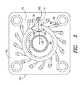
FIG. 5 provides a top view of a cross-section of the fuel injector taken along section line 5-5 as shown in FIG. 3;
FIG. 6 provides a top view of a cross-section of the fuel injector taken along section line 6-6 as shown in FIG. 3; and
FIG. 7 provides a cross-section side view of the fuel injector as shown in FIG. 3, according to at least one embodiment of the present invention.
DETAILED DESCRIPTION OF THE INVENTION
Reference will now be made in detail to present embodiments of the invention, one or more examples of which are illustrated in the accompanying drawings. The detailed description uses numerical and letter designations to refer to features in the drawings. Like or similar designations in the drawings and description have been used to refer to like or similar parts of the invention. As used herein, the terms “first”, “second”, and “third” may be used interchangeably to distinguish one component from another and are not intended to signify location or importance of the individual components. The terms “upstream,” “downstream,” “radially,” and “axially” refer to the relative direction with respect to fluid flow in a fluid pathway. For example, “upstream” refers to the direction from which the fluid flows, and “downstream” refers to the direction to which the fluid flows. Similarly, “radially” refers to the relative direction substantially perpendicular to the fluid flow, and “axially” refers to the relative direction substantially parallel to the fluid flow.
Each example is provided by way of explanation of the invention, not limitation of the invention. In fact, it will be apparent to those skilled in the art that modifications and variations can be made in the present invention without departing from the scope or spirit thereof. For instance, features illustrated or described as part of one embodiment may be used on another embodiment to yield a still further embodiment. Thus, it is intended that the present invention covers such modifications and variations as come within the scope of the appended claims and their equivalents. Although exemplary embodiments of the present invention will be described generally in the context of a fuel injector for a combustor incorporated into a gas turbine for purposes of illustration, one of ordinary skill in the art will readily appreciate that embodiments of the present invention may be applied to any combustor incorporated into any turbomachine and is not limited to a gas turbine combustor unless specifically recited in the claims.
Referring now to the drawings, wherein identical numerals indicate the same elements throughout the figures, FIG. 1 provides a functional block diagram of an exemplary gas turbine 10 that may incorporate various embodiments of the present invention. As shown, the gas turbine 10 generally includes an inlet section 12 that may include a series of filters, cooling coils, moisture separators, and/or other devices to purify and otherwise condition a working fluid (e.g., air) 14 entering the gas turbine 10. The working fluid 14 flows to a compressor section where a compressor 16 progressively imparts kinetic energy to the working fluid 14 to produce a compressed working fluid 18 at a highly energized state. The compressed working fluid 18 flows to a combustion section where one or more combustors 20 ignite fuel 22 from a fuel supply 23 with the compressed working fluid 18 to produce combustion gases 24 having a high temperature and pressure. The combustion gases 24 flow through a turbine section having a turbine 26 to produce work. For example, the turbine 26 may be connected to a shaft 28 so that rotation of the turbine 26 drives the compressor 16 to produce the compressed working fluid 18. Alternately or in addition, the shaft 28 may connect the turbine 26 to a generator 30 for producing electricity. Exhaust gases 32 from the turbine 26 flow through an exhaust section 34 that may connect the turbine 26 to an exhaust stack 36 downstream from the turbine 26. The exhaust section 34 may include, for example, a heat recovery steam generator (not shown) for cleaning and extracting additional heat from the exhaust gases 32 prior to release to the environment.
The combustors 20 may be any type of combustor known in the art, and the present invention is not limited to any particular combustor design unless specifically recited in the claims. FIG. 2 provides a simplified side cross-section view of an exemplary combustor 20 according to various embodiments of the present invention. As shown in FIG. 2, a casing 40 and an end cover 42 may combine to contain the compressed working fluid 18 flowing to the combustor 20. A cap assembly 44 may extend radially across at least a portion of the combustor 20, and one or more axially extending fuel nozzles 46 may be radially arranged across the cap assembly 44 to supply the fuel 22 to a combustion chamber 48 downstream from the cap assembly 44. A liner 50 may circumferentially surround at least a portion of the combustion chamber 48, and a transition duct 52 downstream from the liner 50 may connect the combustion chamber 48 to the inlet of the turbine 26. An impingement sleeve 54 with flow holes 56 may circumferentially surround the transition duct 52, and a flow sleeve 58 may circumferentially surround the liner 50. In this manner, the compressed working fluid 18 may pass through the flow holes 56 in the impingement sleeve 54 to flow through an annular passage 60 outside of the transition duct 52 and liner 50 to provide convective cooling to the transition duct 52 and liner 50. When the compressed working fluid 18 reaches the end cover 42, the compressed working fluid 18 reverses its direction to flow through the fuel nozzles 46 and cap assembly 44 into the combustion chamber 48.
The combustor 20 may further include one or more fuel injectors 62 downstream from the fuel nozzles 46 that that may provide a late lean injection of fuel 22 and compressed working fluid 18 for combustion. FIG. 3 provides a perspective view of the fuel injector 62 as shown in FIG. 2 according to at least one embodiment of the present invention, and FIG. 4 provides an enlarged side cross-section view of the fuel injector 62 as shown in FIG. 3. As shown in FIG. 3, the fuel injector 62 generally includes an outer body 64 having an upstream end 66 axially separated from a downstream end 68 with respect to an axial centerline of the fuel injector 62.
An inlet 70 extends through the upstream end 66 of the outer body 64. A radial swirler 72 is disposed at the upstream end 66 of the outer body 64. The radial swirler 72 includes a first radial passage 74 that extends at least partially circumferentially around the inlet 70 of the outer body 64, and a second radial passage 76 that extends axially outward from the first radial passage 74 with respect to the axial centerline of the fuel injector 62. The first radial passage 74 includes a first plurality of radially extending swirler vanes 78 that project axially through the first radial passage 74 with respect to the axial centerline of the fuel injector 62. The radially extending swirler vanes of the first plurality of radially extending swirler vanes 78 are arranged in an annular array that at least partially surrounds the inlet 70 of the outer body 64. The second radial passage 76 includes a second plurality of radially extending swirler vanes 80 that project axially through the second radial passage 76 with respect to the axial centerline of the fuel injector 62. As shown in FIG. 3, at least some of the first plurality of radially extending swirler vanes 78 includes one or more fuel injection ports 82. In addition or in the alternative, at least some of the second plurality of radially extending swirler vanes 80 includes one or more fuel injection ports 84.
In particular embodiments, a cap plate 86 is disposed axially outward from the upstream end 66 of the outer body 64. The cap plate 86 extends radially across the second radial passage 76 of the radial swirler 72. A radially extending annular plate 88 is disposed between the first radial passage 74 and the second radial passage 76. The annular plate 88 may at least partially separate the first radial passage 74 from the second radial passage 76.
In particular embodiments, as shown in FIG. 4, the outer body 64 at least partially defines a fuel circuit 90 that extends at least partially through the outer body 64 of the fuel injector 62. The fuel circuit 90 may be in fluid communication with the fuel supply 23 through a series of fluid conduits that extend within and/or through the casing 40 of the combustion section as shown in FIG. 2. The fuel circuit 90 may be configured to flow a gaseous fuel and/or a liquid fuel. In various embodiments, as shown in FIG. 4, a fuel passage 92 is defined between the fuel circuit 90 and the fuel injection ports 82, 84 of the first and/or the second plurality of radially extending swirler vanes 78, 80.
As further illustrated in FIG. 4, the outer body 64 at least partially defines an outer flow passage 94 that extends through the outer body 64. The first radial passage 74 being in fluid communication with the outer flow passage 94. An inner flow passage 96 extends from the second radial passage 76 through the first radial passage 74 and at least partially through the outer flow passage 94. The inner flow passage 96 being at least partially defined by an inner body 98 having an outlet 99 at a downstream end. The inner body 98 extends downstream from the second radial passage 76. In particular embodiments, the annular plate 88 at least partially defines an inlet 100 to the inner flow passage 96. The inlet 100 may be conical shaped to route the compressed working fluid 18 and/or fuel from the second radial passage 76 into the inner flow passage 96. In further embodiments, the annular plate 88 at least partially defines the inner flow passage 96. As shown, the outer body 64 of the fuel injector 62 extends at least partially through the liner 50 and/or the flow sleeve 58 to define a flow path into the combustion chamber 48 and/or into the liner 50 downstream from the combustion chamber.
FIG. 5 provides a cross-section top view of the first radial passage 74 of the fuel injector 62 as shown in FIG. 3 taken along section line 5-5, and FIG. 6 provides a cross-section top view of the second radial passage 76 of the fuel injector 62 as shown in FIG. 3 taken along section line 6-6. As shown in FIG. 5, each radially extending swirler vane 78 of the first plurality of radially extending swirler vanes 78 disposed within the first radial passage 74 includes a leading edge or radially outer point 102 and a trailing edge 104. The trailing edge 104 being arranged at a first swirl angle 106 with respect to a line 108 that extends radially between the axial centerline of the fuel injector 62 and the leading edge 102 of the swirler vane 78 through a plane that is perpendicular to the axial centerline of the fuel injector 62. A first swirl angle 106 that is greater than zero degrees as shown in FIG. 5 corresponds to a first rotational direction 110 such as a counter-clockwise direction with respect to the axial centerline of the fuel injector 62. A first swirl angle 106, as illustrated by dotted lines 111, that is less than zero degrees corresponds to a second rotational direction 112 such as a clockwise direction with respect to the axial centerline of the fuel injector 62.
As shown in FIG. 6, each radially extending swirler vane 80 of the second plurality of radially extending swirler vanes 80 disposed within the second radial passage 76 includes a leading edge or radially outer point 114 and a trailing edge 116. The trailing edge 116 being arranged at a second swirl angle 118 with respect to a line 120 that extends radially between the axial centerline of the fuel injector 62 and the leading edge 114 of the swirler vane 80 through a plane that is perpendicular to the axial centerline of the fuel injector 62. A second swirl angle 118 that is greater than zero degrees as illustrated by dotted lines 122 corresponds to the first rotational direction 110 such as a counter-clockwise direction with respect to the axial centerline of the fuel injector 62. A second swirl angle 118 that is less than zero degrees as shown in FIG. 6 corresponds to the second rotational direction 112 such as a clockwise direction with respect to the axial centerline of the fuel injector 62.
In particular embodiments, the first swirl angle 106 is between about forty degrees and about sixty degrees. In particular embodiments, the second swirl angle 118 is between about negative forty degrees and about forty degrees. In particular embodiments, the first swirl angle 106 and the second swirl angle 118 produce co-rotating swirl or rotation in the same direction within the first radial passage 74 and the second radial passage 76 respectively. For example, where the first swirl angle 106 and the second swirl angle 118 are both greater than or less than zero degrees. In other embodiments, the first swirl angle 106 and the second swirl angle 118 produce counter-rotating swirl or rotation in opposite rotational directions within the first radial passage 74 and the second radial passage 76 respectively.
In operation, as shown in FIGS. 3 through 6, a first portion of the compressed working fluid 18 from the compressor is routed into the first radial passage 74 of the fuel injector 62. Fuel 22 is injected through the fuel injection ports 82 of the first plurality of radially extending swirler vanes 78. The first plurality of radially extending swirler vanes 88 impart radial swirl at a first swirl angle 106 to the first portion of the compressed working fluid 18 and/or to the fuel 22. The first portion of the compressed working fluid 18 and the fuel 22 are mixed in the first radial flow passage 74 and/or the outer flow passage 94 as the combination flows towards the outlet 68 of the outer body 64. Simultaneously, a second portion of the compressed working fluid 18 is routed into the second radial passage 76 of the fuel injector 62. Fuel 22 is injected through the fuel injection ports 84 of the second plurality of radially extending swirler vanes 80. The second plurality of radially extending swirler vanes 80 impart radial swirl to the second portion of the compressed working fluid 18 and/or to the fuel 22 at a second swirl angle 118 which is generally less than the first swirl angle 106 of the first plurality of radially extending swirler vanes 78. The second portion of the compressed working fluid 18 and the fuel 22 are mixed in the inner flow passage 96 as the combination flows towards the outlet 99 of the inner body 98. By having different first and second swirl angles 106, 118 and/or different flow rates through the first and second radial passages 74, 76 premixing of the fuel 22 and the compressed working fluid 18 flowing from the fuel injector 62 into the combustion chamber 48 is enhanced, thereby improving mixture with a swirling flow of fuel and compressed working that flows into the combustion chamber from the axially extending fuel nozzles. As a result, peak flame temperature within the combustor is reduced, thus reducing the NOx production. In addition, the radial swirl within the inner flow passage may be less than the radial swirl within the outer flow passage, thereby preventing the generation of a recirculation zone inside the fuel injector.
FIG. 7 provides a cross-section view of the fuel injector 62 as shown in FIG. 2, according to at least one alternate embodiment of the present invention. As shown in FIG. 7, the fuel injector 62 may further include a liquid fuel plenum 124. One or more fuel injection ports 126 provide for fluid communication between the liquid fuel plenum 124 and the second radial passage 76 and/or the inner flow passage 96. As shown, the liquid fuel plenum 124 may be coupled to the cap plate 86 of the fuel injector 62. The liquid fuel plenum 124 may at least partially define an axial flow path 126 that extends at least partially through the liquid fuel plenum 124 and into at least one of the second radial flow passage 76 or the inner flow passage 96.
In the embodiment as shown in FIG. 7, the compressed working fluid 18 flows into the second radial passage 76 where the second plurality of swirler vanes 80 imparts radial swirl to the compressed working fluid 18 in either the first or the second rotational directions 110, 112. A liquid fuel 128 is atomized as it is injected from the liquid fuel plenum 124 into the second radial passage 76 and/or into the inner flow passage 96. The radially swirling compressed working fluid 18 premixes with a first portion 130 of the liquid fuel 128 as the mixture flows through the inner flow passage 96 towards an outlet 132 of the inner body 98. A second portion 134 of the liquid fuel 128 comprising of larger droplets of the liquid fuel than the first portion 130 may centrifuge to the inner body 98. The second portion 134 of the liquid fuel 128 is pushed through the inner body 98 by the swirling motion of the mixture of the compressed working fluid 18 and the liquid fuel 128 as it flows axially outward from the inner flow passage 96. As the second portion 134 of the liquid fuel 128 flows across an edge 136 of the outlet 132 of the inner body 98, the swirling compressed working fluid 18 flowing through the outer flow passage 94 air blasts or further atomizes the second portion 134 of the liquid fuel 128, thereby improving mixing of the liquid fuel 128 and the compressed working fluid 18 within the fuel injector 62 before it is introduced into the combustion chamber 48 and/or through the liner 50 downstream of the combustion chamber 48.
The invention as disclosed herein and as illustrated in FIGS. 2 through 7 provide various technological advantages and/or improvements over existing fuel injectors and combustors. The invention maintains a high swirl angle and reasonable axial velocity within the outer flow passage to enhance mixing inside the swirler and to enhance the mixing of the fuel and air flowing from the fuel injector with fuel and air supplied to the combustion chamber from the axially extending fuel nozzles which reduces the peak flame temperature and thus reduces production of undesirable emissions such as oxides of nitrogen or NOx. In addition, the reduced swirl from inner swirler prevents generation of a recirculation zone inside the swirler which reduces thermal stress on the fuel injector. Another benefit of the invention is that the fuel-to-air ratio or volume of fuel divided by the volume of air profile at the fuel injector exit can be controlled so that the NOx performance can be optimized. As a result, various embodiments of the present invention may allow extended combustor operating conditions, extend the life and/or maintenance intervals for various combustor components, maintain adequate design margins of flame holding, and/or reduce undesirable emissions.
This written description uses examples to disclose the invention, including the best mode, and also to enable any person skilled in the art to practice the invention, including making and using any devices or systems and performing any incorporated methods. The patentable scope of the invention is defined by the claims, and may include other examples that occur to those skilled in the art. Such other examples are intended to be within the scope of the claims if they include structural elements that do not differ from the literal language of the claims, or if they include equivalent structural elements with insubstantial differences from the literal language of the claims.

Claims (17)

What is claimed is:
1. A fuel injector for a combustor, the fuel injector comprising:
a. an annular outer body having an inlet at an upstream end, the outer body at least partially defining an outer flow passage;
b. an inner flow passage that extends at least partially through the outer flow passage of the outer body; and
c. a radial swirler disposed at the inlet of the outer body of the fuel injector, the radial swirler comprising:
a radially extending cap plate disposed at a top portion of the radial swirler;
a radially extending annular plate disposed between the inlet of the outer body and the cap plate, the annular plate at least partially defining an inner flow passage that extends within the outer flow passage;
a first radial passage having a first plurality of swirler vanes that extend axially between the upstream end of the outer body and the annular plate, wherein the first radial passage is in fluid communication with the outer flow passage of the outer body, wherein the first plurality of swirler vanes is oriented perpendicular to an axial centerline of the fuel injector;
a second radial passage having a second plurality of swirler vanes that extend axially between the annular plate and the cap plate, wherein the second radial passage is in fluid communication with the inner flow passage, wherein the second plurality of swirler vanes is oriented perpendicular to the axial centerline of the fuel injector; and
a liquid fuel plenum that extends through the cap plate, the liquid fuel plenum being in fluid communication with at least one of the second radial passage or the inner flow passage.
2. The fuel injector as in claim 1, further comprising an axial flow path that extends at least partially through the liquid fuel plenum and into at least one of the second radial passage or the inner flow passage.
3. The fuel injector as in claim 1, further comprising a fuel circuit that extends at least partially through the outer body, wherein at least one of the swirler vanes of the first plurality of swirler vanes or at least one of the swirler vanes of the second plurality of swirler vanes includes a fuel injection port, the fuel injection port being in fluid communication with the fuel circuit.
4. The fuel injector as in claim 1, further comprising an annular inner body that further defines the inner flow passage, wherein the inner body extends downstream from the annular plate.
5. The fuel injector as in claim 1, wherein each swirler vane of the first plurality of swirler vanes includes a leading edge and a trailing edge, the trialing edge being arranged at a first swirl angle with respect to a first radial line that extends between the axial centerline of fuel infector and the leading edge.
6. The fuel injector as in claim 5, wherein each swirler vane of the second plurality of swirler vanes includes a leading edge and a trailing edge, the trialing edge being arranged at a second swirl angle with respect to a second radial line that extends between the axial centerline of fuel injector and the leading edge, wherein the first swirl angle with respect to the first radial line and the second swirl angle with respect to the second radial line are different.
7. A gas turbine comprising:
a. a compressor, a combustor downstream from the compressor and a turbine downstream from the combustor, the combustor comprising:
a combustion chamber;
a liner that circumferentially surrounds at least a portion of the combustion chamber;
a plurality of fuel nozzles coupled to an end cover of the combustor and extending axially downstream from the end cover and terminating upstream from the combustion chamber; and
a fuel injector that extends radially through the liner downstream from the plurality of fuel nozzles, the fuel injector comprising:
(1) an annular outer body defining an inlet, an outlet and an outer flow passage, wherein the outer flow passage tapers radially inwardly along an axial centerline of the fuel injector from the inlet to the outlet;
(2) an inner flow passage that extends at least partially through the outer flow passage; and
(3) a radial swirler disposed at the inlet of the outer body, the radial swirler having a first radial passage including a first plurality of swirler vanes and a second radial passage including a second plurality of swirler vanes, the first radial passage being in fluid communication with the outer flow passage and the second radial passage being in fluid communication with the inner flow passage, wherein at least one of the swirler vanes of the first plurality of swirler vanes includes a fuel injection port and at least one of the swirler vanes of the second plurality of swirler vanes includes a fuel injection port.
8. The gas turbine as in claim 7, wherein each swirler vane of the first plurality of swirler vanes includes a leading edge and a trailing edge, the trialing edge being arranged at a first swirl angle with respect to a first radial line that extends between the axial centerline of fuel injector and the leading edge.
9. The gas turbine as in claim 8, wherein each swirler vane of the second plurality of swirler vanes includes a leading edge and a trailing edge, the trialing edge being arranged at a second swirl angle with respect to a second radial line that extends between the axial centerline of fuel injector and the leading edge, wherein the first swirl angle with respect to the first radial line and the second swirl angle with respect to the second radial line are different.
10. The gas turbine as in claim 7, wherein the fuel injector further comprises a fuel circuit defined within the outer body, wherein the fuel injection port of the swirler vane of the first plurality of swirler vanes and the fuel injection port of the swirler vane of the second plurality of swirler vanes are in fluid communication with the fuel circuit.
11. A fuel injector for a combustor, the fuel injector comprising:
an annular outer body defining an inlet, an outlet and an outer flow passage, wherein the outer flow passage tapers radially inwardly along an axial centerline of the fuel injector from the inlet to the outlet; and
a radial swirler extending radially across and axially outwardly from an upstream end of the outer body, the radial swirler including a cap plate, an annular plate disposed axially between the cap plate and the upstream end of the outer body, a first plurality of swirler vanes that extends from the upstream end of the outer body to the annular plate within a first radial passage defined therebetween and a second plurality of swirler vanes that extends from the annular plate to the cap plate within a second radial passage defined therebetween;
wherein the annular plate defines an inner sleeve that defines an inner flow passage within the outer flow passage, wherein the first radial passage is in fluid communication with the outer flow passage and wherein the inner flow passage is in fluid communication with the second radial passage.
12. The fuel injector as in claim 11, wherein the inner sleeve terminates upstream from the outlet of the outer tow passage.
13. The fuel injector as in claim 11, further comprising a fuel circuit at least partially within the outer body, wherein the fuel injection port of the swirler vane of the first plurality of swirler vanes and the fuel injection port of the swirler vane of the second plurality of swirler vanes are in fluid communication with the fuel circuit.
14. The fuel injector as in claim 11, wherein each swirler vane of the first plurality of swirler vanes includes a leading edge and a trailing edge, the trialing edge being arranged at a first swirl angle with respect to a first radial line that extends between the axial centerline of fuel injector and the leading edge.
15. The fuel injector as in claim 14, wherein each swirler vane of the second plurality of swirler vanes includes a leading edge and a trailing edge, the trialing edge being arranged at a second swirl angle with respect to a second radial line that extends between the axial centerline of fuel injector and the leading edge.
16. The fuel injector as in claim 15, wherein the first swirl angle with respect to the first radial line and the second swirl angle with respect to the second radial line are different.
17. The fuel injector as in claim 15, wherein the first swirl angle is between about forty degrees to sixty degrees and the second swirl angle is between about negative forty degrees to about forty degrees.
US13/735,340 2013-01-07 2013-01-07 Fuel injector for supplying fuel to a combustor Expired - Fee Related US9534790B2 (en)

Priority Applications (4)

Application Number Priority Date Filing Date Title
US13/735,340 US9534790B2 (en) 2013-01-07 2013-01-07 Fuel injector for supplying fuel to a combustor
JP2013270677A JP2014132214A (en) 2013-01-07 2013-12-27 Fuel injector for supplying fuel to combustor
DE102013114973.1A DE102013114973A1 (en) 2013-01-07 2013-12-30 Fuel injector for supplying fuel to a combustion chamber
CH02167/13A CH707456A2 (en) 2013-01-07 2013-12-31 A fuel injector for supplying fuel to a combustion chamber.

Applications Claiming Priority (1)

Application Number Priority Date Filing Date Title
US13/735,340 US9534790B2 (en) 2013-01-07 2013-01-07 Fuel injector for supplying fuel to a combustor

Publications (2)

Publication Number Publication Date
US20140190170A1 US20140190170A1 (en) 2014-07-10
US9534790B2 true US9534790B2 (en) 2017-01-03

Family

ID=51059907

Family Applications (1)

Application Number Title Priority Date Filing Date
US13/735,340 Expired - Fee Related US9534790B2 (en) 2013-01-07 2013-01-07 Fuel injector for supplying fuel to a combustor

Country Status (4)

Country Link
US (1) US9534790B2 (en)
JP (1) JP2014132214A (en)
CH (1) CH707456A2 (en)
DE (1) DE102013114973A1 (en)

Cited By (6)

* Cited by examiner, † Cited by third party
Publication number Priority date Publication date Assignee Title
US20160209039A1 (en) * 2015-01-21 2016-07-21 United Technologies Corporation Bluff body fuel mixer
US10309655B2 (en) * 2014-08-26 2019-06-04 Siemens Energy, Inc. Cooling system for fuel nozzles within combustor in a turbine engine
US20190178497A1 (en) * 2017-12-11 2019-06-13 General Electric Company Fuel injection assemblies for axial fuel staging in gas turbine combustors
US11060728B2 (en) 2017-11-09 2021-07-13 Doosan Heavy Industries & Construction Co., Ltd. Combustor and gas turbine including the same
US11079111B2 (en) * 2019-04-29 2021-08-03 Solar Turbines Incorporated Air tube
US11137144B2 (en) 2017-12-11 2021-10-05 General Electric Company Axial fuel staging system for gas turbine combustors

Families Citing this family (20)

* Cited by examiner, † Cited by third party
Publication number Priority date Publication date Assignee Title
US9297534B2 (en) 2011-07-29 2016-03-29 General Electric Company Combustor portion for a turbomachine and method of operating a turbomachine
US20130111918A1 (en) * 2011-11-07 2013-05-09 General Electric Company Combustor assembly for a gas turbomachine
JP6463947B2 (en) * 2014-11-05 2019-02-06 川崎重工業株式会社 Burner, combustor, and gas turbine
FR3044765B1 (en) * 2015-12-08 2018-11-23 Safran Aircraft Engines AIR INTAKE CHIMNEY FOR FIRM TURBOMACHINE TEST BENCH
US9976487B2 (en) * 2015-12-22 2018-05-22 General Electric Company Staged fuel and air injection in combustion systems of gas turbines
US20170260866A1 (en) * 2016-03-10 2017-09-14 Siemens Energy, Inc. Ducting arrangement in a combustion system of a gas turbine engine
CN109563997B (en) * 2016-08-03 2021-01-12 西门子股份公司 Duct arrangement with injector assembly configured to form a shielding air flow injected into a combustion section of a gas turbine engine
WO2018026381A1 (en) * 2016-08-03 2018-02-08 Siemens Aktiengesellschaft Combustion system with injector assemblies arranged to recapture cooling air in a combustor wall to form a shielding flow of air in a combustion stage
US10527286B2 (en) 2016-12-16 2020-01-07 Delavan, Inc Staged radial air swirler with radial liquid fuel distributor
US10344981B2 (en) * 2016-12-16 2019-07-09 Delavan Inc. Staged dual fuel radial nozzle with radial liquid fuel distributor
US10634355B2 (en) * 2016-12-16 2020-04-28 Delavan Inc. Dual fuel radial flow nozzles
US10513987B2 (en) * 2016-12-30 2019-12-24 General Electric Company System for dissipating fuel egress in fuel supply conduit assemblies
JP2018146193A (en) * 2017-03-08 2018-09-20 トヨタ自動車株式会社 Liquid fuel burner
US10690349B2 (en) * 2017-09-01 2020-06-23 General Electric Company Premixing fuel injectors and methods of use in gas turbine combustor
US11156164B2 (en) 2019-05-21 2021-10-26 General Electric Company System and method for high frequency accoustic dampers with caps
US11174792B2 (en) 2019-05-21 2021-11-16 General Electric Company System and method for high frequency acoustic dampers with baffles
KR102164620B1 (en) * 2019-06-19 2020-10-12 두산중공업 주식회사 Combustor and gas turbine including the same
US11846421B2 (en) * 2020-02-14 2023-12-19 Rtx Corporation Integrated fuel swirlers
US11280495B2 (en) * 2020-03-04 2022-03-22 General Electric Company Gas turbine combustor fuel injector flow device including vanes
US20230212984A1 (en) * 2021-12-30 2023-07-06 General Electric Company Engine fuel nozzle and swirler

Citations (9)

* Cited by examiner, † Cited by third party
Publication number Priority date Publication date Assignee Title
US6192688B1 (en) 1996-05-02 2001-02-27 General Electric Co. Premixing dry low nox emissions combustor with lean direct injection of gas fule
US7137258B2 (en) 2004-06-03 2006-11-21 General Electric Company Swirler configurations for combustor nozzles and related method
US20100058767A1 (en) 2008-09-05 2010-03-11 General Electric Company Swirl angle of secondary fuel nozzle for turbomachine combustor
US20100170252A1 (en) 2009-01-07 2010-07-08 General Electric Company Late lean injection for fuel flexibility
US20100170216A1 (en) 2009-01-07 2010-07-08 General Electric Company Late lean injection system configuration
US20110113784A1 (en) * 2009-11-18 2011-05-19 Paul Headland Swirler Vane, Swirler and Burner Assembly
US20110277481A1 (en) 2010-05-17 2011-11-17 General Electric Company Late lean injection injector
US20120102958A1 (en) 2010-10-28 2012-05-03 General Electric Company Late lean injection manifold
US20120266604A1 (en) * 2011-04-21 2012-10-25 Predrag Popovic Fuel nozzle and method for operating a combustor

Family Cites Families (4)

* Cited by examiner, † Cited by third party
Publication number Priority date Publication date Assignee Title
EP0554325B1 (en) * 1990-10-23 1995-07-26 ROLLS-ROYCE plc Gasturbine combustion chamber and method of operation thereof
US6339923B1 (en) * 1998-10-09 2002-01-22 General Electric Company Fuel air mixer for a radial dome in a gas turbine engine combustor
JP3809465B2 (en) * 2000-12-28 2006-08-16 株式会社豊田中央研究所 Premixed combustor for gas turbine and fuel supply control device and method thereof
GB2432655A (en) * 2005-11-26 2007-05-30 Siemens Ag Combustion apparatus

Patent Citations (9)

* Cited by examiner, † Cited by third party
Publication number Priority date Publication date Assignee Title
US6192688B1 (en) 1996-05-02 2001-02-27 General Electric Co. Premixing dry low nox emissions combustor with lean direct injection of gas fule
US7137258B2 (en) 2004-06-03 2006-11-21 General Electric Company Swirler configurations for combustor nozzles and related method
US20100058767A1 (en) 2008-09-05 2010-03-11 General Electric Company Swirl angle of secondary fuel nozzle for turbomachine combustor
US20100170252A1 (en) 2009-01-07 2010-07-08 General Electric Company Late lean injection for fuel flexibility
US20100170216A1 (en) 2009-01-07 2010-07-08 General Electric Company Late lean injection system configuration
US20110113784A1 (en) * 2009-11-18 2011-05-19 Paul Headland Swirler Vane, Swirler and Burner Assembly
US20110277481A1 (en) 2010-05-17 2011-11-17 General Electric Company Late lean injection injector
US20120102958A1 (en) 2010-10-28 2012-05-03 General Electric Company Late lean injection manifold
US20120266604A1 (en) * 2011-04-21 2012-10-25 Predrag Popovic Fuel nozzle and method for operating a combustor

Cited By (9)

* Cited by examiner, † Cited by third party
Publication number Priority date Publication date Assignee Title
US10309655B2 (en) * 2014-08-26 2019-06-04 Siemens Energy, Inc. Cooling system for fuel nozzles within combustor in a turbine engine
US20160209039A1 (en) * 2015-01-21 2016-07-21 United Technologies Corporation Bluff body fuel mixer
US9797601B2 (en) * 2015-01-21 2017-10-24 United Technologies Corporation Bluff body fuel mixer
US10816209B2 (en) 2015-01-21 2020-10-27 Raytheon Technologies Corporation Bluff body fuel mixer
US11060728B2 (en) 2017-11-09 2021-07-13 Doosan Heavy Industries & Construction Co., Ltd. Combustor and gas turbine including the same
US20190178497A1 (en) * 2017-12-11 2019-06-13 General Electric Company Fuel injection assemblies for axial fuel staging in gas turbine combustors
US11137144B2 (en) 2017-12-11 2021-10-05 General Electric Company Axial fuel staging system for gas turbine combustors
US11187415B2 (en) * 2017-12-11 2021-11-30 General Electric Company Fuel injection assemblies for axial fuel staging in gas turbine combustors
US11079111B2 (en) * 2019-04-29 2021-08-03 Solar Turbines Incorporated Air tube

Also Published As

Publication number Publication date
CH707456A2 (en) 2014-07-15
DE102013114973A1 (en) 2014-07-24
US20140190170A1 (en) 2014-07-10
JP2014132214A (en) 2014-07-17

Similar Documents

Publication Publication Date Title
US9534790B2 (en) Fuel injector for supplying fuel to a combustor
US9353950B2 (en) System for reducing combustion dynamics and NOx in a combustor
US9835333B2 (en) System and method for utilizing cooling air within a combustor
US8904798B2 (en) Combustor
US9151500B2 (en) System for supplying a fuel and a working fluid through a liner to a combustion chamber
US9714767B2 (en) Premix fuel nozzle assembly
JP6266290B2 (en) Fuel nozzle for gas turbine engine combustor
US9371989B2 (en) Combustor nozzle and method for supplying fuel to a combustor
US8550809B2 (en) Combustor and method for conditioning flow through a combustor
US20140174090A1 (en) System for supplying fuel to a combustor
US10570821B2 (en) Pre-film liquid fuel cartridge
US20130227955A1 (en) System and method for reducing combustion dynamics in a combustor
US10215415B2 (en) Premix fuel nozzle assembly cartridge
US20180149364A1 (en) Combustor with axially staged fuel injection
US9322559B2 (en) Fuel nozzle having swirler vane and fuel injection peg arrangement
US9951956B2 (en) Fuel nozzle assembly having a premix fuel stabilizer
US10030869B2 (en) Premix fuel nozzle assembly
US20130283802A1 (en) Combustor
US20130227953A1 (en) System and method for reducing combustion dynamics in a combustor
JP6595010B2 (en) Fuel nozzle assembly having a premix flame stabilizer
JP2017166811A (en) Axially staged fuel injector assembly mounting
US20170184310A1 (en) System for Injecting a Liquid Fuel into a Combustion Gas Flow Field
US10344978B2 (en) Combustion liner cooling
US20130122437A1 (en) Combustor and method for supplying fuel to a combustor
US10228135B2 (en) Combustion liner cooling

Legal Events

Date Code Title Description
AS Assignment

Owner name: GENERAL ELECTRIC COMPANY, NEW YORK

Free format text: ASSIGNMENT OF ASSIGNORS INTEREST;ASSIGNORS:CAI, JUN;BOARDMAN, GREGORY ALLEN;KARIM, HASAN;AND OTHERS;REEL/FRAME:029577/0705

Effective date: 20130104

STCF Information on status: patent grant

Free format text: PATENTED CASE

FEPP Fee payment procedure

Free format text: MAINTENANCE FEE REMINDER MAILED (ORIGINAL EVENT CODE: REM.); ENTITY STATUS OF PATENT OWNER: LARGE ENTITY

LAPS Lapse for failure to pay maintenance fees

Free format text: PATENT EXPIRED FOR FAILURE TO PAY MAINTENANCE FEES (ORIGINAL EVENT CODE: EXP.); ENTITY STATUS OF PATENT OWNER: LARGE ENTITY

STCH Information on status: patent discontinuation

Free format text: PATENT EXPIRED DUE TO NONPAYMENT OF MAINTENANCE FEES UNDER 37 CFR 1.362

FP Lapsed due to failure to pay maintenance fee

Effective date: 20210103