EP2107310A1 - Burner - Google Patents
Burner Download PDFInfo
- Publication number
- EP2107310A1 EP2107310A1 EP08006662A EP08006662A EP2107310A1 EP 2107310 A1 EP2107310 A1 EP 2107310A1 EP 08006662 A EP08006662 A EP 08006662A EP 08006662 A EP08006662 A EP 08006662A EP 2107310 A1 EP2107310 A1 EP 2107310A1
- Authority
- EP
- European Patent Office
- Prior art keywords
- fuel
- quarl
- flame
- burner
- main
- Prior art date
- Legal status (The legal status is an assumption and is not a legal conclusion. Google has not performed a legal analysis and makes no representation as to the accuracy of the status listed.)
- Withdrawn
Links
Images


Classifications
-
- F—MECHANICAL ENGINEERING; LIGHTING; HEATING; WEAPONS; BLASTING
- F23—COMBUSTION APPARATUS; COMBUSTION PROCESSES
- F23R—GENERATING COMBUSTION PRODUCTS OF HIGH PRESSURE OR HIGH VELOCITY, e.g. GAS-TURBINE COMBUSTION CHAMBERS
- F23R3/00—Continuous combustion chambers using liquid or gaseous fuel
- F23R3/28—Continuous combustion chambers using liquid or gaseous fuel characterised by the fuel supply
- F23R3/286—Continuous combustion chambers using liquid or gaseous fuel characterised by the fuel supply having fuel-air premixing devices
-
- F—MECHANICAL ENGINEERING; LIGHTING; HEATING; WEAPONS; BLASTING
- F23—COMBUSTION APPARATUS; COMBUSTION PROCESSES
- F23R—GENERATING COMBUSTION PRODUCTS OF HIGH PRESSURE OR HIGH VELOCITY, e.g. GAS-TURBINE COMBUSTION CHAMBERS
- F23R3/00—Continuous combustion chambers using liquid or gaseous fuel
- F23R3/28—Continuous combustion chambers using liquid or gaseous fuel characterised by the fuel supply
- F23R3/34—Feeding into different combustion zones
- F23R3/343—Pilot flames, i.e. fuel nozzles or injectors using only a very small proportion of the total fuel to insure continuous combustion
-
- F—MECHANICAL ENGINEERING; LIGHTING; HEATING; WEAPONS; BLASTING
- F23—COMBUSTION APPARATUS; COMBUSTION PROCESSES
- F23R—GENERATING COMBUSTION PRODUCTS OF HIGH PRESSURE OR HIGH VELOCITY, e.g. GAS-TURBINE COMBUSTION CHAMBERS
- F23R3/00—Continuous combustion chambers using liquid or gaseous fuel
- F23R3/28—Continuous combustion chambers using liquid or gaseous fuel characterised by the fuel supply
- F23R3/34—Feeding into different combustion zones
- F23R3/346—Feeding into different combustion zones for staged combustion
-
- F—MECHANICAL ENGINEERING; LIGHTING; HEATING; WEAPONS; BLASTING
- F23—COMBUSTION APPARATUS; COMBUSTION PROCESSES
- F23D—BURNERS
- F23D2900/00—Special features of, or arrangements for burners using fluid fuels or solid fuels suspended in a carrier gas
- F23D2900/00014—Pilot burners specially adapted for ignition of main burners in furnaces or gas turbines
Definitions
- the present invention refers to a burner preferably for use in gas turbine engines, and more particularly to a burner adapted to stabilize engine lean partially premixed (LPP) combustion process and engine turndown requirements, and further to a burner that use a pilot combustor to provide combustion products (radicals and heat) to stabilize a main lean partially premixed combustion process.
- LPP partially premixed
- Gas turbine engines are employed in a variety of applications including electric power generation, military and commercial aviation, pipeline transmission and marine transportation.
- fuel and air are provided to a burner chamber where they are mixed and ignited by a flame, thereby initiating combustion.
- the major problems associated with the combustion process in gas turbine engines, in addition to thermal efficiency and proper mixing of the fuel and the air, are associated to flame stabilization, the elimination of pulsations and noise, and the control of polluting emissions, especially nitrogen oxides (NOx), CO, UHC, smoke and particulated emission
- flame temperature is reduced by an addition of more air than required for the combustion process itself.
- the excess air that is not reacted must be heated during combustion, and as a result flame temperature of the combustion process is reduced (below stoichiometric point) from approximately 2300K to 1800 K and below.
- This reduction in flame temperature is required in order to significantly reduce NOx emissions.
- a method shown to be most successful in reducing Nox emissions is to make combustion process so lean that the temperature of the flame is reduced below the temperature at which diatomic Nitrogen and Oxygen (N2 and 02) dissociate and recombine into NO and N02.
- Swirl stabilized combustion flows are commonly used in industrial gas turbine engines to stabilize combustion by, as indicated above, developing reverse flow (Swirl Induced Recirculation Zone) about the centreline, whereby the reverse flow returns heat and free radicals back to the incoming un-burnt fuel and air mixture.
- the heat and free radicals from the previously reacted fuel and air are required to initiate (pyrolyze fuel and initiate chain branching process) and sustain stable combustion of the fresh un-reacted fuel and air mixture.
- Stable combustion in gas turbine engines requires a cyclic process of combustion producing combustion products that are transported back upstream to initiate the combustion process. A flame front is stabilised in a Shear-Layer of the Swirl Induced Recirculation Zone.
- a lean-rich partially premixed low emissions burner for a gas turbine combustor that provides stable ignition and combustion process at all engine load conditions.
- This burner operates according to the principle of "supplying" heat and high concentration of free radicals from a pilot combustor exhaust to a main flame burning in a lean premixed air/fuel swirl, whereby a rapid and stable combustion of the main lean premixed flame is supported.
- the pilot combustor supplies heat and supplements a high concentration of free radicals directly to a forward stagnation point and a shear layer of.the main swirl induced recirculation zone, where the main lean premixed flow is mixed with hot gases products of combustion provided by the pilot combustor. This allows a leaner mix and lower temperatures of the main premixed air/fuel swirl combustion that otherwise would not be self-sustaining in swirl stabilized recirculating flows during the operating conditions of the burner.
- the disclosed burner provides stable ignition and combustion process at all engine load conditions.
- a target in this design/invention is to have uniform mixing profiles at the exit of lean premixing channels.
- Two distinct combustion zones exist within the burner covered by this disclosure, where fuel is burnt simultaneously at all times. Both combustion zones are swirl stabilized and fuel and air are premixed prior to the combustion process.
- a main combustion process during which more than 90 % of fuel is burned, is lean.
- a bluff body is not needed in the pilot combustor as the present invention uses un un-quenched flow of radicals directed downstream from a combustion zone of the pilot combustor along a centre line of the pilot combustor, said flow of radicals being released through the full opening area of a throat of the pilot combustor at an exit of the pilot combustor.
- the main reason why the supporting combustion process in the small pilot combustor could be lean, stoichiometric or rich and still provide stable ignition and combustion process at all engine load conditions is related to combustion efficiency.
- the combustion process which occurs within the small combustor-pilot, has low efficiency due to the high surface area which results in flame quenching on the walls of the pilot combustor.
- Inefficient combustion process either being lean, stoichiometric or rich, could generate a large pool of active species - radicals which is necessary to enhance stability of the main lean flame and is beneficial for a successful operation of the present burner design/invention (Note: the flame occurring in the premixed lean air/fuel mixture is herein called the lean flame).
- Relatively large amount of fuel can be added to the small pilot combustor cooling air which corresponds to very rich equivalence ratios ( ⁇ > 3).
- Swirled cooling air and fuel and hot products of combustion from the small pilot combustor can very effectively sustain combustion of the main lean flame below, at and above LBO limits.
- the combustion process is very stable and efficient because hot combustion products and very hot cooling air (above 750 °C), premixed with fuel, provide heat and active species (radicals) to the forward stagnation point of the main flame recirculation zone.
- the small pilot combustor combined with very hot cooling air (above 750 °C) premixed with fuel act as a flameless burner, where reactants (oxygen & fuel ) are premixed with products of combustion and a distributed flame is established at the forward stagnation point of the swirl induced recirculation zone.
- the imparted level of swirl and the swirl number (equation 1) is above the critical one (not lower then 0,6 and not higher then 0,8) at which vortex breakdown - recirculation zone will form and will be firmly positioned within the multi quarl arrangement.
- the forward stagnation point P should be located within the quarl and at the exit of the pilot combustor. The main reasons, for this requirement, are;
- a weak, recirculation zone will form and unstable combustion can occur.
- a strong recirculation zone is required to enable transport of heat and free radicals from the previously combusted fuel and air, back upstream towards the flame front.
- a well established and a strong recirculation zone is required to provide a shear layer region where turbulent flame speed can "match" or be proportional to the local fuel/air mixture, and a stable flame can establish This flame front established in the shear layer of the main recirculation zone has to be steady and no periodic movements or procession of the flame front should occur.
- the imparted swirl number can be high, but should not be higher then 0.8, because at and above this swirl number more then 80% of the total amount of the flow will be recirculated back. A further increase in swirl number will not contribute more to the increase in the amount of the recirculated mass of the combustion products, and the flame in the shear layer of the recirculation zone will be subjected to high turbulence and strain which can result in quenching and partial extinction and reignition of the flame.
- Any type of the swirl generator, radial, axial and axial-radial can be used in the burner, covered by this disclosure. In this disclosure a radial swirler configuration is shown.
- the burner utilizes aerodynamics stabilization of the flame and confines the flame stabilization zone - the recirculation zone - in the multiple quarl arrangement.
- the multiple quarl arrangement is an important feature of the design of the provided burner for the following reasons.
- the quarl (or also called diffuser):
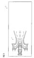
- FIG 1 the burner is depicted with the burner 1 having a housing 2 enclosing the burner components.
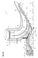
- Figure 2a shows for the sake of clarity a cross sectional view of the burner above a rotational symmetry axis.
- the main parts of the burner are the radial swirler 3, the multi quarl 4a, 4b, 4c and the pilot combustor 5.
- the burner loperates according to the principle of "supplying" heat and high concentration of free radicals from the a pilot combustor 5 exhaust 6 to a main flame 7 burning in a lean premixed air/fuel swirl emerging from a first exit 8 of a first lean premixing channel 10 and from a second exit 9 of a second lean premixing channel 11, whereby a rapid and stable combustion of the main lean premixed flame 7 is supported.
- Said first lean premixing channel 10 is formed by and between the walls 4a and.4b of the multi quarl.
- the second lean premixing channel 11 is formed by and between the walls 4b and 4c of the multi quarl.
- the outermost rotational symmetric wall 4c of the multi quarl is provided with an extension 4c1 to provide for the optimal length of the multi quarl arrangement.
- the first 10 and second 11 lean premixing channels are provided with swirler wings forming the swirler 3 to impart rotation to the air/fuel mixture passing through the channels.
- Air 12 is provided to the first 10 and second 11 channels at the inlet 13 of said first and second channels.
- the swirler 3 is located close to the inlet 13 of the first and second channels.
- fuel 14 is introduced to the air/fuel swirl through a tube 15 provided with small diffusor holes 15a located at the air 12 inlet 13 between the swirler 3 wings, whereby the fuel is distributed into the air flow through said holes as a spray and effectively mixed with the air flow. Additional fuel can be added through a second tube 16 emerging into the first channel 10.
- the flame 7 is generated as a conical rotational symmetric shear layer 18 around a main recirculation zone 20 (below sometimes abbreviated RZ).
- the flame 7 is enclosed inside the extension 4c1 of the outermost quarl, in this example quarl 4c.
- the pilot combustor 5 supplies heat and supplements a high concentration of free radicals directly to a forward stagnation point P and the shear layer 18 of the main swirl induced recirculation zone 20, where the main lean premixed flow is mixed with hot gases products of combustion provided by the pilot combustor 5.
- the pilot combustor 5 is provided with walls 21 enclosing a combustion room for a pilot combustion zone 22. Air is supplied to the combustion room through fuel channel 23 and air channel 24.
- a distributor plate 25 provided with holes over the surface of the plate. Said distributor plate 25 is separated a certain distance from said walls 21 forming a cooling space layer 25a. Cooling air 26 is taken in through a cooling inlet 27 and meets the outside of said distributor plate 25, whereupon the cooling air 26 is distributed across the walls 21 of the pilot combustor to effectively cool said walls 21.
- the cooling air 26, now heated to up to 1000 K, is after said cooling let out through a second swirler 28 arranged around a pilot quarl 29 of the pilot combustor 5.
- Further fuel can be added to the combustion in the main lean flame 7 by supplying fuel in a duct 30 arranged around and outside the cooling space layer 25a. Said further fuel is then let out and into the second swirler 28, where the now hot cooling air 26 and the fuel added through duct 30 is effectively premixed ( Fig. 2a ).
- the heated cooling air (26) is supplied to the main flame (7) at the most upstream end of the main flame (5) close to the forward stagnation point P.
- said cooling air 26 is in a heated state supplied to said main flame 7 as one of:
- a relatively large amount of fuel can be added to the small pilot combustor 5 cooling air which corresponds to very rich equivalence ratios ( ⁇ > 3).
- Swirled cooling air and fuel and hot products of combustion from the small pilot combustor can very effectively sustain combustion of the main lean flame 7 below, at and above LBO limits.
- the combustion process is very stable and efficient because hot combustion products and very hot cooling air (above 750 °C), premixed with fuel, provide heat and active species (radicals) to the forward stagnation point P of the main flame recirculation zone 20.
- the small pilot combustor 5 combined with very hot cooling air (above 750 °C) premixed with fuel act as a flameless burner, where reactants (oxygen & fuel ) are premixed with products of combustion and a distributed flame is established at the forward stagnation point P of the swirl induced recirculation zone 20.
- the imparted level of swirl and the swirl number (equation 1) is above the critical one (not lower then 0.6 and not higher then 0.8, see also fig. 3 ) at which vortex breakdown - recirculation zone 20 - will form and will be firmly positioned within the multi quarl 4a, 4b, 4c arrangement.
- the forward stagnation point P should be located within the quarl 4a, 4b, 4c and at the exit 6 of the pilot combustor 5.
- the imparted level of swirl (the ratio between tangential and axial momentum) has to be higher then the critical one (0.4-0.6), so that a stable central recirculation zone 20 can form.
- the critical swirl number, S N is also a function of the burner geometry, which is the reason for why it varies between 0.4 and 0.6. If the imparted swirl number is ⁇ 0.4 or in the range of 0.4 to 0.6, the main recirculation zone 20, may not form at all or may form and extinguish periodically at low frequencies (below 150Hz) and the resulting aerodynamics could be very unstable which will result in a transient combustion process.
- flame stabilization can occur if: turbulent flame speed ( ST) > local velocity of the fuel air mixture (UF/A).
- Recirculating products which are: source of heat and active species (symbolized by means of arrows 1a and 1b), located within the recirculation zone 20, have to be stationary in space and time downstream from the mixing section of the burner 1 to enable pyrolysis of the incoming mixture of fuel and air. If a steady combustion process is not prevailing, thermo-acoustics instabilities will occur. Swirl stabilized flames are up to five times shorter and have significantly leaner blow-off limits then jet flames. A premixed or turbulent diffusion combustion swirl provides an effective way of premixing fuel and air. The entrainiment of the fuel/air mixture into the shear layer of the recirculation zone 20 is proportional to the strength of the recirculation zone, the swirl number and the characteristics recirculation zone velocity URZ.
- the characteristics recirculation zone velocity, URZ can be expressed as: wherein:
- Active species - radicals In the swirl stabilized combustion, the process is initiated and stabilized by means of transporting heat and free radicals 31 from the previously combusted fuel and air, back upstream towards the flame front 7. If the combustion process is very lean, as is the case in lean-partially premixed combustion systems, and as a result the combustion temperature is low, the equilibrium levels of free radicals is also very low. Also, at high engine pressures the free radicals produced by the combustion process, quickly relax, see Fig. 6 , to the equilibrium level that corresponds to the temperature of the combustion products. This is due to the fact that the rate of this relaxation of the free radicals to equilibrium increases exponentially with increase in pressure, while on the other hand the equilibrium level of free radicals decreases exponentially with temperature decrease.
- the relaxation time of the free radicals can be short compared to the "transport" time required for the free radicals (symbolized by arrows 31) to be convected downstream, from the point where they were produced in the shear layer 18 of the main recirculation zone 20, back upstream, towards the flame front 7 and the forward stagnation point P of the main recirculation zone 20.
- This invention utilizes high non-equilibrium levels of free radicals 32 to stabilize the main lean combustion 7.
- the scale of the small pilot combustor 5 is kept small and most of the combustion of fuel occurs in the lean premixed main combustor (at 7 and 18), and not in the small pilot combustor 5.
- the small pilot combustor 5, can be kept small, because the free radicals 32 are released near the forward stagnation point P of the main recirculation zone 20. This is generally the most efficient location to supply additional heat and free radicals to swirl stabilized combustion (7).
- the time scale between quench and utilization of free radicals 32 is very short not allowing free radicals 32 to relax to low equilibrium levels.
- the forward stagnation point P of the main-lean re-circulating zone 20 is maintained and aerodynamically stabilized in the quarl (4a), at the exit 6 of the small pilot combustor 5.
- zone 22 the exit of the small pilot combustor 5 is positioned on the centerline and at the small pilot combustor 5 throat 33.
- the burner utilizes aerodynamics stabilization of the flame and confines the flame stabilization zone - recirculation zone (20), in the multiple quarl arrangement (4a, 4b and 4c).
- the multiple quarl arrangement is an important feature of the disclosed burner design for the reasons listed below.
- the quarl (or sometimes called the diffuser):
- the quarl (or diffuser) and the imparted swirl provides a possibility of a simple scaling of the disclosed burner geometry for different burner powers.
- the igniter 34 as in prior art burners, is placed in the outer recirculation zone, which is illustrated in Figure 4b , the fuel/air mixture entering this region must often be made rich in order to make the flame temperature sufficiently hot to sustain stable combustion in this region.
- the flame then often cannot be propagated to the main recirculation until the main premixed fuel and airflow becomes sufficiently rich, hot and has a sufficient pool of free radicals, which occurs at higher fuel flow rates.
- the flame cannot propagate from the outer recirculation zone to the inner main recirculation zone shortly after ignition, it must propagate at higher pressure after the engine speed begins to increase.
- the present invention also allows for the ignition of the main combustion 7 to occur at the forward stagnation point P of the main recirculation zone 20.
- Most gas turbine engines must use an outer recirculation zone, see Figure 4b , as the location where the spark, or torch igniter, ignites the engine. Ignition can only occur if stable combustion can also occur; otherwise the flame will just blow out immediately after ignition.
- the inner or main recirculation zone 22, as in the present invention, is generally more successful at stabilizing the flame, because the recirculated gas 31 is transported back and the heat from the combustion products of the recirculated gas 31 is focused to a small region at the forward stagnation point P of the main recirculation zone 20.
- the combustion - flame front 7 also expands outwards in a conical shape from this forward stagnation point P, as illustrated in Figure 2 .
- This conical expansion downstream allows the heat and free radicals 32 generated upstream to support the combustion downstream allowing the flame front 7 to widen as it moves downstream.
- the quarl (4a, 4b, 4c), illustrated in Figure 2 compared to swirl stabilized combustion without the quarl, shows how the quarl shapes the flame to be more conical and less hemispheric in nature.
- a more conical flame front allows for a point source of heat to initiate combustion of the whole flow field effectively.
- the combustion process within the burner 1 is staged.
- lean flame 35 is initiated in the small pilot combustor 5 by adding fuel 23 mixed with air 24 and igniting the mixture utilizing ignitor 34.
- ignition equivalence ratio of the flame 35 in the small pilot combustor 5 is adjusted at either lean (below equivalence ratio 1, and at approximately equivalence ratio of 0,8) or rich conditions (above equivalence ratio 1, and at approximately equivalence ratio between 1,4 and 1,6).
- lean low equivalence ratio 1, and at approximately equivalence ratio of 0,8
- rich conditions above equivalence ratio 1, and at approximately equivalence ratio between 1,4 and 1,6.
- the reason why the equivalence ratio within the small pilot combustor 5 is at rich conditions in the range between 1,4 and 1,6 is emission levels.
- the amount of the fuel which can be added to the hot cooling air can correspond to equivalence ratios >3.
- a third part and full load stage fuel 14 is gradually added to the air 12, which is the main air flow to the main flame 7.
Abstract
The invention relates to a burner for a gas turbine comprising a burner housing (2). It is one object of the invention to provide a lean-rich partially premixed low emission burner for a gas turbine combustor that provides stable ignition and combustion process at all engine load conditions. According to the invention enclosed in that housing is a burner, at the upstream end of that burner (1) a pilot combustor (5) creating a flow of an unquenched concentration of radicals (32) and heat. Respectively provided is: a plurality of quarl sections (4a, 4b, 4c) surrounding the exit (6) of the pilot combustor (5), a main combustion room defined downstream said pilot combustor (5) and at least a first channel (10) defined as an annular space between an upstream quarl section (4a) and the closest downstream quarl section (4b) providing air (12) and fuel (14) to a main flame (7) in said combustion room.
Description
- The present invention refers to a burner preferably for use in gas turbine engines, and more particularly to a burner adapted to stabilize engine lean partially premixed (LPP) combustion process and engine turndown requirements, and further to a burner that use a pilot combustor to provide combustion products (radicals and heat) to stabilize a main lean partially premixed combustion process.
- Gas turbine engines are employed in a variety of applications including electric power generation, military and commercial aviation, pipeline transmission and marine transportation. In a gas turbine engine which operates in LPP mode, fuel and air are provided to a burner chamber where they are mixed and ignited by a flame, thereby initiating combustion. The major problems associated with the combustion process in gas turbine engines, in addition to thermal efficiency and proper mixing of the fuel and the air, are associated to flame stabilization, the elimination of pulsations and noise, and the control of polluting emissions, especially nitrogen oxides (NOx), CO, UHC, smoke and particulated emission
- In industrial gas turbine engines, which operate in LPP mode, flame temperature is reduced by an addition of more air than required for the combustion process itself. The excess air that is not reacted must be heated during combustion, and as a result flame temperature of the combustion process is reduced (below stoichiometric point) from approximately 2300K to 1800 K and below. This reduction in flame temperature is required in order to significantly reduce NOx emissions. A method shown to be most successful in reducing Nox emissions is to make combustion process so lean that the temperature of the flame is reduced below the temperature at which diatomic Nitrogen and Oxygen (N2 and 02) dissociate and recombine into NO and N02. Swirl stabilized combustion flows are commonly used in industrial gas turbine engines to stabilize combustion by, as indicated above, developing reverse flow (Swirl Induced Recirculation Zone) about the centreline, whereby the reverse flow returns heat and free radicals back to the incoming un-burnt fuel and air mixture. The heat and free radicals from the previously reacted fuel and air are required to initiate (pyrolyze fuel and initiate chain branching process) and sustain stable combustion of the fresh un-reacted fuel and air mixture. Stable combustion in gas turbine engines requires a cyclic process of combustion producing combustion products that are transported back upstream to initiate the combustion process. A flame front is stabilised in a Shear-Layer of the Swirl Induced Recirculation Zone. Within the Shear-Layer "Local Turbulent Flame Speed of the Air/Fuel Mixture" has to be higher then "Local Air/Fuel Mixture Velocity" and as a result the Flame Front/combustion process can be stabilised.
- Lean premixed combustion is inherently less stable than diffusion flame combustion for the following reasons:
- 1. The amount of air required to reduce the flame temperature from 2300K to 1700-1800 K is approximately twice the amount of air required for stoichiometric combustion. This makes the overall fuel/air ratio (□) very close (around or below 0.5; □ ≥ 0.5) or similar to a fuel/air ratio at which lean extinction of the premixed flame occurs. Under these conditions the flame can locally extinguish and re-light in a periodic manner.
- 2. Near the lean extinction limit the flame speed of the lean partially premixed flames is very sensitive to the equivalence ratio fluctuations. Fluctuations in flame speed can result in spatial fluctuations/movements of the flame front (Swirl Induced Recirculation Zone). A less stable, easy to move flame front of a pre-mixed flame results in a periodic heat release rate, that, in turn, results in movement of the flame, unsteady fluid dynamic processes, and thermo-acoustic instabilities develop.
- 3. Equivalence ratio fluctuations are probably the most common coupling mechanism to link unsteady heat release to unsteady pressure oscillations.
- 4. In order to make the combustion sufficiently lean, in order to be able to significantly reduce NOx emissions, nearly all of the air used in the engine must go through the injector and has to be premixed with fuel.
Therefore, all the flow in the burners has the potential to be reactive and requires that the point where combustion is initiated is fixed. - 5. when the heat required for reactions to occur is the stability-limiting factor, very small temporal fluctuations in fuel/air equivalence ratios (which could either result either from fluctuation of fuel or air flow through the Burner/Injector) can cause flame to partially extinguish and re-light.
- 6. An additional and very important reason for the decrease in stability in the pre-mixed flame is that the steep gradient of fuel and air mixing is eliminated from the combustion process. This makes the premixed flow combustible anywhere where there is a sufficient temperature for reaction to occur. When the flame can, more easily, occur in multiple positions, it becomes more unstable. The only means for stabilizing a premixed flame to a fixed position are based on the temperature gradient produced where the unburnt premixed fuel and air mix with the hot products of combustion (flame cannot occur where the temperature is too low).
This leaves the thermal gradient produced by the generation, radiation, diffusion and convection of heat as a method to stabilize the premixed flame. Radiation heating of the fluid does not produce a sharp gradient; therefore, stability must come from the generation, diffusion and convection of heat into the pre-reacted zone. Diffusion only produces a sharp gradient in laminar flow and not turbulent flows, leaving only convection and energy generation to produce the sharp gradients desired for flame stabilization which is actually heat and free radial gradients. Both, heat and free radial gradients, are generated, diffused and convected by the same mechanisms through recirculating products of combustion within the Swir1 Induced Recirculation Zone. - 7. In pre-mixed flows, as well as diffusion flows, rapid expansion causing separations and swirling recirculating flows, are both commonly used to produce gradients of heat and free radicals into the pre-reacted fuel and air. Document
WO 2005/040682 A2 describes a solution directed to a burner for gas turbine engines that use a pilot flame to assist in sustaining and stabilizing the combustion process. - Disclosed is a lean-rich partially premixed low emissions burner for a gas turbine combustor that provides stable ignition and combustion process at all engine load conditions. This burner operates according to the principle of "supplying" heat and high concentration of free radicals from a pilot combustor exhaust to a main flame burning in a lean premixed air/fuel swirl, whereby a rapid and stable combustion of the main lean premixed flame is supported. The pilot combustor supplies heat and supplements a high concentration of free radicals directly to a forward stagnation point and a shear layer of.the main swirl induced recirculation zone, where the main lean premixed flow is mixed with hot gases products of combustion provided by the pilot combustor. This allows a leaner mix and lower temperatures of the main premixed air/fuel swirl combustion that otherwise would not be self-sustaining in swirl stabilized recirculating flows during the operating conditions of the burner.
- According to a first aspect of the invention there is herein presented a burner characterized by the features of
claim 1. - According to a second aspect of the invention there is presented a method for burning a fuel as characterized in the independent method claim.
- Further aspects of the invention are presented in the dependent claims.
- The burner utilizes; A swirl of air/fuel above swirl number (SN) 0,7 (that is above critical SN=0,6), generated-imparted into the flow, by a radial swirler; active species -non-equilibrium free radicals being released close to the forward stagnation point, particular type of the burner geometry with a multi quarl device, and internal staging of fuel and air within the burner to stabilize combustion process at all gas turbine operating conditions. In short, the disclosed burner provides stable ignition and combustion process at all engine load conditions. Some important features related to the inventive burner are:
- the geometric location of the burner elements;
- the amount of fuel and air staged within the burner;
- the minimum amount of active species - radicals generated and
- required at different engine/burner operating conditions; fuel profile;
- mixing of fuel and air at different engine operating conditions;
- imparted level of swirl;
- multi (minimum double quarl) quarl arrangement.
- To achieve as low as possible emission levels, a target in this design/invention is to have uniform mixing profiles at the exit of lean premixing channels. Two distinct combustion zones exist within the burner covered by this disclosure, where fuel is burnt simultaneously at all times. Both combustion zones are swirl stabilized and fuel and air are premixed prior to the combustion process. A main combustion process, during which more than 90 % of fuel is burned, is lean. A supporting combustion process, which occurs within the small pilot combustor, wherein up to 1% of the total fuel flow is consumed, could be lean, stoichiometric and rich (equivalence ratio, Φ=1.4 and higher).
- An important difference between the disclosed burner and a burner as presented in the prior art document is that a bluff body is not needed in the pilot combustor as the present invention uses un un-quenched flow of radicals directed downstream from a combustion zone of the pilot combustor along a centre line of the pilot combustor, said flow of radicals being released through the full opening area of a throat of the pilot combustor at an exit of the pilot combustor.
- The main reason why the supporting combustion process in the small pilot combustor could be lean, stoichiometric or rich and still provide stable ignition and combustion process at all engine load conditions is related to combustion efficiency. The combustion process, which occurs within the small combustor-pilot, has low efficiency due to the high surface area which results in flame quenching on the walls of the pilot combustor. Inefficient combustion process, either being lean, stoichiometric or rich, could generate a large pool of active species - radicals which is necessary to enhance stability of the main lean flame and is beneficial for a successful operation of the present burner design/invention (Note: the flame occurring in the premixed lean air/fuel mixture is herein called the lean flame).
- It would be very difficult to sustain (but not to ignite, because the small pilot combustor can act as a torch igniter) combustion in the shear layer of the main recirculation zone below LBO (Lean Blow Off) limits of the main lean flame ( approx. T > 1350 K and Φ ≥ 0.25). For engine operation below LBO limits of the main lean flame, in this burner design, additional "staging" of the small combustor-pilot is used/provided. The air which is used to cool the small pilot combustor internal walls (performed by a combination of impingement and convecting cooling) and which represents approximately 5-8 % of the total air flow through the burner, is premixed with fuel prior the swirler. Relatively large amount of fuel can be added to the small pilot combustor cooling air which corresponds to very rich equivalence ratios (Φ > 3). Swirled cooling air and fuel and hot products of combustion from the small pilot combustor, can very effectively sustain combustion of the main lean flame below, at and above LBO limits. The combustion process is very stable and efficient because hot combustion products and very hot cooling air (above 750 °C), premixed with fuel, provide heat and active species (radicals) to the forward stagnation point of the main flame recirculation zone. During this combustion process the small pilot combustor, combined with very hot cooling air (above 750 °C) premixed with fuel act as a flameless burner, where reactants (oxygen & fuel ) are premixed with products of combustion and a distributed flame is established at the forward stagnation point of the swirl induced recirculation zone.
- To enable a proper function and stable operation of the burner disclosed in the present application, it is required that the imparted level of swirl and the swirl number (equation 1) is above the critical one (not lower then 0,6 and not higher then 0,8) at which vortex breakdown - recirculation zone will form and will be firmly positioned within the multi quarl arrangement. The forward stagnation point P should be located within the quarl and at the exit of the pilot combustor. The main reasons, for this requirement, are;
- If the imparted level of swirl is low and the resulting swirl number is below 0,6, for most burner geometries, a weak, recirculation zone will form and unstable combustion can occur.
A strong recirculation zone is required to enable transport of heat and free radicals from the previously combusted fuel and air, back upstream towards the flame front. A well established and a strong recirculation zone is required to provide a shear layer region where turbulent flame speed can "match" or be proportional to the local fuel/air mixture, and a stable flame can establish This flame front established in the shear layer of the main recirculation zone has to be steady and no periodic movements or procession of the flame front should occur. The imparted swirl number can be high, but should not be higher then 0.8, because at and above this swirl number more then 80% of the total amount of the flow will be recirculated back. A further increase in swirl number will not contribute more to the increase in the amount of the recirculated mass of the combustion products, and the flame in the shear layer of the recirculation zone will be subjected to high turbulence and strain which can result in quenching and partial extinction and reignition of the flame. Any type of the swirl generator, radial, axial and axial-radial can be used in the burner, covered by this disclosure. In this disclosure a radial swirler configuration is shown. - The burner utilizes aerodynamics stabilization of the flame and confines the flame stabilization zone - the recirculation zone - in the multiple quarl arrangement. The multiple quarl arrangement is an important feature of the design of the provided burner for the following reasons. The quarl (or also called diffuser):
- provides a flame front (main recirculation zone) anchoring the flame in a defined position in space, without a need to anchore the flame to a solid surface/bluff body, and in that way a high thermal loading and issues related to the burner mechanical integrity are avoided;
- geometry (quarl half angle α and length L) is important to control size and shape of the recirculation zone in conjunction with the swirl number. The length of the recirculation zone is roughly proportional to 2 to 2,5 of the quarl length;
- optimal length L is of the order of L/D =1 (D is the quarl throat diameter). The minimum length of the quarl should not be smaller then L/D=0,5 and not longer then L/D=2;
- optimal quarl half angle α should not be smaller then 20 and larger then 25 degrees, allows for a lower swirl before decrease in stability, when compared to a less confined flame front; and
- has the important task to control the size and shape of the recirculation zone as the expansion of the hot gases as a result of combustion reduces transport time of free radicals in the recirculation zone.
-
-
Fig. 1 is a simplified cross section schematically showing the burner according to the aspects of the invention enclosed in a housing without any details showing how the burner is configured inside said housing. -
Fig. 2a is a cross section through the burner schematically showing a section above a symmetry axis, whereby a rotation around the symmetry axis forms a rotational body displaying a layout of the burner. -
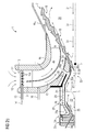
Fig. 2b is a cross section through the burner according toFig. 2a , with the difference that air cooling the pilot combustor is let out to an air/fuel premix channel serving the main flame with air and fuel. -
Fig. 2c is a cross section of the burner ofFig. 2a , wherein the air cooling the pilot combustor is let out according to a mix of the disclosures ofFig. 2a andFig. 2b . -
Figure 3 shows a diagram of stability limits of the flame as a function of the swirl number, imparted level of swirl and equivalence ratio. -
Figure 4a : shows a diagram of combustor near field aerodynamics. -
Figure 4b ; shows a diagram of combustor near field aerodynamics. -
Figure 5 shows a diagram of turbulence intensity. -
Figure 6 shows a diagram of relaxation time as a function of combustion pressure. - In the following a number of embodiments will be described in more detail with references to the enclosed drawings.
- In
figure 1 the burner is depicted with theburner 1 having ahousing 2 enclosing the burner components. -
Figure 2a shows for the sake of clarity a cross sectional view of the burner above a rotational symmetry axis. The main parts of the burner are theradial swirler 3, themulti quarl pilot combustor 5. - As stated, the burner loperates according to the principle of "supplying" heat and high concentration of free radicals from the a
pilot combustor 5exhaust 6 to a main flame 7 burning in a lean premixed air/fuel swirl emerging from afirst exit 8 of a firstlean premixing channel 10 and from asecond exit 9 of a secondlean premixing channel 11, whereby a rapid and stable combustion of the main lean premixed flame 7 is supported. Said firstlean premixing channel 10 is formed by and between thewalls 4a and.4b of the multi quarl. The secondlean premixing channel 11 is formed by and between thewalls 4b and 4c of the multi quarl. The outermost rotational symmetric wall 4c of the multi quarl is provided with an extension 4c1 to provide for the optimal length of the multi quarl arrangement. The first 10 and second 11 lean premixing channels are provided with swirler wings forming theswirler 3 to impart rotation to the air/fuel mixture passing through the channels. -
Air 12 is provided to the first 10 and second 11 channels at theinlet 13 of said first and second channels. According to the embodiment shown theswirler 3 is located close to theinlet 13 of the first and second channels. Further,fuel 14 is introduced to the air/fuel swirl through atube 15 provided withsmall diffusor holes 15a located at theair 12inlet 13 between theswirler 3 wings, whereby the fuel is distributed into the air flow through said holes as a spray and effectively mixed with the air flow. Additional fuel can be added through asecond tube 16 emerging into thefirst channel 10. - When the lean premixed air/fuel flow is burnt the main flame 7 is generated. The flame 7 is formed as a conical rotational
symmetric shear layer 18 around a main recirculation zone 20 (below sometimes abbreviated RZ). The flame 7 is enclosed inside the extension 4c1 of the outermost quarl, in this example quarl 4c. - The
pilot combustor 5 supplies heat and supplements a high concentration of free radicals directly to a forward stagnation point P and theshear layer 18 of the main swirl inducedrecirculation zone 20, where the main lean premixed flow is mixed with hot gases products of combustion provided by thepilot combustor 5. - The
pilot combustor 5 is provided withwalls 21 enclosing a combustion room for apilot combustion zone 22. Air is supplied to the combustion room throughfuel channel 23 andair channel 24. Around thewalls 21 of thepilot combustor 5 there is adistributor plate 25 provided with holes over the surface of the plate.Said distributor plate 25 is separated a certain distance from saidwalls 21 forming acooling space layer 25a. Coolingair 26 is taken in through a coolinginlet 27 and meets the outside of saiddistributor plate 25, whereupon the coolingair 26 is distributed across thewalls 21 of the pilot combustor to effectively cool saidwalls 21. The coolingair 26, now heated to up to 1000 K, is after said cooling let out through asecond swirler 28 arranged around apilot quarl 29 of thepilot combustor 5. Further fuel can be added to the combustion in the main lean flame 7 by supplying fuel in aduct 30 arranged around and outside the cooling space layer 25a. Said further fuel is then let out and into thesecond swirler 28, where the nowhot cooling air 26 and the fuel added throughduct 30 is effectively premixed (Fig. 2a ). According to this embodiment (a) the heated cooling air (26) is supplied to the main flame (7) at the most upstream end of the main flame (5) close to the forward stagnation point P. - In alternative embodiments (see
figures 2b and2c ) saidcooling air 26 is in a heated state supplied to said main flame 7 as one of: - b) the
heated cooling air 26 is let out into saidfirst channel 10 through anopening 28a, thus introduced to said main flame 7 from achannel 10 running through thequarl Fig. 2b ). - c) the cooling air is provided to said main lean partially premixed combustion process as a mix of a) and b) as the heated cooling air is let out to the first channel through said
opeing 28a and also through a smallannular channel 28b around the quarl of thepilot combustor 5.
In embodiment b) the heated cooling air is provided close to the inside of the walls offirst channel 10 and introduced into the main flame further downstream when compared to embodiment a). In embodiment c) a major part of theheated cooling air 26 is let out to thefirst channel 20 throughopening 28a and a minor part is let out to the main flame 7 through said small annular channel 28b. Said minor part could be less than 10 % of the heated cooling 26 air and preferably around 1% of theheated cooling air 26 - A relatively large amount of fuel can be added to the
small pilot combustor 5 cooling air which corresponds to very rich equivalence ratios (Φ > 3). Swirled cooling air and fuel and hot products of combustion from the small pilot combustor, can very effectively sustain combustion of the main lean flame 7 below, at and above LBO limits. The combustion process is very stable and efficient because hot combustion products and very hot cooling air (above 750 °C), premixed with fuel, provide heat and active species (radicals) to the forward stagnation point P of the mainflame recirculation zone 20. During this combustion process thesmall pilot combustor 5, combined with very hot cooling air (above 750 °C) premixed with fuel act as a flameless burner, where reactants (oxygen & fuel ) are premixed with products of combustion and a distributed flame is established at the forward stagnation point P of the swirl inducedrecirculation zone 20. - To enable a proper function and stable operation of the
burner 1 disclosed in the present application, it is required that the imparted level of swirl and the swirl number (equation 1) is above the critical one (not lower then 0.6 and not higher then 0.8, see alsofig. 3 ) at which vortex breakdown - recirculation zone 20 - will form and will be firmly positioned within themulti quarl quarl exit 6 of thepilot combustor 5. Some main reasons, for this requirement, were mentioned in the summary above. A further reason is: - If the swirl number is larger than 0,8, the swirling flow will extend to the exit of the combustor, which can result in an overheating of subsequent guide vanes of a turbine.

- Where r is the radial coordinate direction, the limits of the integrals are the inner and outer radii of an annular tube carrying the air, R1 and R2, respectively. U, and W are the axial and radial swirl components and p is the local static pressure
- Below is presented a summary of the imparted level of swirl and swirl number requirements. See also
Figures 4a and4b . - The imparted level of swirl (the ratio between tangential and axial momentum) has to be higher then the critical one (0.4-0.6), so that a stable
central recirculation zone 20 can form. The critical swirl number, SN, is also a function of the burner geometry, which is the reason for why it varies between 0.4 and 0.6. If the imparted swirl number is ≤ 0.4 or in the range of 0.4 to 0.6, themain recirculation zone 20, may not form at all or may form and extinguish periodically at low frequencies (below 150Hz) and the resulting aerodynamics could be very unstable which will result in a transient combustion process. - In the
shear layer 18 of the stable andsteady recirculation zone 20, with strong velocity gradient and turbulence levels, flame stabilization can occur if: turbulent flame speed ( ST) > local velocity of the fuel air mixture (UF/A). - Recirculating products which are: source of heat and active species (symbolized by means of arrows 1a and 1b), located within the
recirculation zone 20, have to be stationary in space and time downstream from the mixing section of theburner 1 to enable pyrolysis of the incoming mixture of fuel and air. If a steady combustion process is not prevailing, thermo-acoustics instabilities will occur.
Swirl stabilized flames are up to five times shorter and have significantly leaner blow-off limits then jet flames.
A premixed or turbulent diffusion combustion swirl provides an effective way of premixing fuel and air.
The entrainiment of the fuel/air mixture into the shear layer of therecirculation zone 20 is proportional to the strength of the recirculation zone, the swirl number and the characteristics recirculation zone velocity URZ. - The characteristics recirculation zone velocity, URZ, can be expressed as:

wherein:

- Experiments (Driscoll1990, Whitelaw1991) have shown that RZ strength = (MR) exp -1/2 (dF/A / dF/A,cent) (URZ / UF/A) (b / dF/A), and MR should be < 1. (dF/A / dF/A,cent), only important for turbulent diffusion flames. recirculation zones size/length is "fixed" and proportional to 2-2.5 dF/A. Not more than approximately 80 % of the mass recirculates back above SN =0.8 independently of how high SN is further increased
Addition of Quarl-diverging walls downstream of the throat of the burner- enhances recirculation (Batchelor 67, Hallet 87, Lauckel 70, Whitelow 90); and Lauckel 70 has found that optimal geometrical parameters were: α = 20° - 25°; L / dF/A,min =1 and higher.
This suggests that dquarl / dF/A = 2 - 3, but stability of the flame suggests that leaner lean blow-off limits were achieved for values close to 2 (Whitelaw 90).
Experiments and practical experience suggest also that UF/A should be above 30-50 m/s for premixed flames due to risks of flashback (Proctor 85).
If a backfacing step is placed at the quarl exit, then external RZ if formed. The length of the external RZ, LERZ is usually 2/3 hERZ. - Active species - radicals In the swirl stabilized combustion, the process is initiated and stabilized by means of transporting heat and
free radicals 31 from the previously combusted fuel and air, back upstream towards the flame front 7. If the combustion process is very lean, as is the case in lean-partially premixed combustion systems, and as a result the combustion temperature is low, the equilibrium levels of free radicals is also very low. Also, at high engine pressures the free radicals produced by the combustion process, quickly relax, seeFig. 6 , to the equilibrium level that corresponds to the temperature of the combustion products. This is due to the fact that the rate of this relaxation of the free radicals to equilibrium increases exponentially with increase in pressure, while on the other hand the equilibrium level of free radicals decreases exponentially with temperature decrease. The higher the level of free radicals available for initiation of combustion the more rapid and stable the combustion process will tend to be. At higher pressures, at which burners in modern gas turbine engines operate in lean partially premixed mode, the relaxation time of the free radicals can be short compared to the "transport" time required for the free radicals (symbolized by arrows 31) to be convected downstream, from the point where they were produced in theshear layer 18 of themain recirculation zone 20, back upstream, towards the flame front 7 and the forward stagnation point P of themain recirculation zone 20. As a consequence, by the time that the reversely circulating flow ofradicals 31 within themain recirculation zone 20 have conveyedfree radicals 31 back towards the flame front 7, and when they begin to mix with the incoming "fresh" premixed lean fuel and air mixture from the first 10 and second 11 channels at the forward stagnation point P to initiate/sustain combustion process, thefree radicals 31 could have reached low equilibrium levels. - This invention utilizes high non-equilibrium levels of
free radicals 32 to stabilize the main lean combustion 7. In this invention, the scale of thesmall pilot combustor 5 is kept small and most of the combustion of fuel occurs in the lean premixed main combustor (at 7 and 18), and not in thesmall pilot combustor 5. Thesmall pilot combustor 5, can be kept small, because thefree radicals 32 are released near the forward stagnation point P of themain recirculation zone 20. This is generally the most efficient location to supply additional heat and free radicals to swirl stabilized combustion (7). As theexit 6 of thesmall pilot combustor 5 is located at the forward stagnation point P of the main-lean re-circulating flow 20, the time scale between quench and utilization offree radicals 32 is very short not allowingfree radicals 32 to relax to low equilibrium levels. The forward stagnation point P of the main-lean re-circulating zone 20 is maintained and aerodynamically stabilized in the quarl (4a), at theexit 6 of thesmall pilot combustor 5. To assure that the distance and time from lean, stochiometric or rich combustion (zone 22), within thesmall pilot combustor 5, is as short and direct as possible, the exit of thesmall pilot combustor 5 is positioned on the centerline and at thesmall pilot combustor 5throat 33. On the centerline, at thesmall pilot combustor 5throat 33, and within thequarl 4a,free radicals 32 are mixed with the products of thelean combustion 31, highly preheated mixture of fuel and air, fromduct 30 andspace 25a, and subsequently withpremixed fuel 14 andair 12 in theshear layer 18 of the leanmain recirculation zone 20. This is very advantageous for highpressure gas turbine engines, which inherently exhibit the most severe thermo acoustic instabilities. Also, because the free radicals and heat produced by thesmall pilot combustor 5 are used efficiently, its size can be small and the quenching process is not required. The possibility to keep the size of thepilot combustor 5, small has also beneficial effect on emissions. - The burner utilizes aerodynamics stabilization of the flame and confines the flame stabilization zone - recirculation zone (20), in the multiple quarl arrangement (4a, 4b and 4c). The multiple quarl arrangement is an important feature of the disclosed burner design for the reasons listed below. The quarl (or sometimes called the diffuser):
- provides a flame front 7 (the
main recirculation zone 20 is anchored without a need to anchore the flame to a solid surface/bluff body and in that way a high thermal loading and issues related to the burner mechanical integrity are avoided, - geometry (quarl half angle α and length L) is important to control the size and shape of the
recirculation zone 20 in conjunction with the swirl number. The length of therecirculation zone 20 is roughly proportional to 2 to 2,5 of the quarl length L, - optimal length is of the order of L/D =1 (D, is quarl throat diameter). The minimum length of the quarl should not be smaller then 0,5 and not longer then 2 (Ref1:The influence of Burner Geometry and Flow Rates on the Stability and Symmetry of Swirl-Stabilized Nonpremixed Flames; V. Milosavljevic et al; Combustion and Flame 80, pages 196-208, 1990),
- optimal quarl half angle α (Refl), should not be smaller then 20 and larger then 25 degrees,
- allows for a lower swirl number before decrease in stability, when compared to less confined flame front,
- is important to control size and shape of recirculation zone due to expansion as a result of combustion and reduces transport time of free radicals in recirculation zone.
- The quarl (or diffuser) and the imparted swirl provides a possibility of a simple scaling of the disclosed burner geometry for different burner powers.
- To scale burner size down (example):
- The
channel 11 should be removed and the shell forming quarl 4c should thus substitute the shell previously formingquarl 4b, which is taken away; the geometry of the quarl 4c should be the same as the geometry of the previously existingquarl 4b, - The Swirl number in
channel 10 should stay the same, - All other Burner parts should be the same; fuel staging within the burner should stay the same or similar.
-
-
Channels - Quarl 4c should be designed in the same as
quarl 4b (formed as a thin splitter plate), - A new third channel (herein fictively called 11b and not disclosed) should be arranged outside and surrounding the
second channel 11 and a new quarl 4d (not shown in the drawings) outside and surrounding thesecond channel 11, thus forming an outer wall of the third channel; the shape of the new quarl 4d should be of a shape similar to the shape of former outmost quarl 4c. - The Swirl number in the channels should be SN,10 > SN,11 > SN,11b, but they should all be above SN=0,6 and not higher then 0,8
- All other burner parts should be the same
- Burner operation and fuel staging within the burner should stay the same or similar.
- When the
igniter 34, as in prior art burners, is placed in the outer recirculation zone, which is illustrated inFigure 4b , the fuel/air mixture entering this region must often be made rich in order to make the flame temperature sufficiently hot to sustain stable combustion in this region. The flame then often cannot be propagated to the main recirculation until the main premixed fuel and airflow becomes sufficiently rich, hot and has a sufficient pool of free radicals, which occurs at higher fuel flow rates. When the flame cannot propagate from the outer recirculation zone to the inner main recirculation zone shortly after ignition, it must propagate at higher pressure after the engine speed begins to increase. This transfer of the initiation of the main flame from the outer recirculation zone pilot only after combustor pressure begins to rise results in more rapid relaxation of the free radicals to low equilibrium levels, which is an undesirable characteristic that is counter productive for ignition of the flame at the forward stagnation point of the main recirculation zone. Ignition of the main recirculation may not occur until the pilot sufficiently raises the bulk temperature to a level where the equilibrium levels of free radicals entrained in the main recirculation zone and the production of addition free radicals in the premixed main fuel and air mixture are sufficient to ignite the main recirculation zone. In the process of getting the flame to propagate from the outer to the main recirculation zone, significant amounts of fuel exits the engine without burning from the un-ignited main premixed fuel and air mixture. A problem occurs if the flame transitions to the main recirculation zone in some burner before others in the same engine, because the burners where the flames are stabilized on the inside burn hotter since all of the fuel is burnt. This leads to a burner-to-burner temperature variation which can damage engine components. - The present invention also allows for the ignition of the main combustion 7 to occur at the forward stagnation point P of the
main recirculation zone 20. Most gas turbine engines must use an outer recirculation zone, seeFigure 4b , as the location where the spark, or torch igniter, ignites the engine. Ignition can only occur if stable combustion can also occur; otherwise the flame will just blow out immediately after ignition. The inner ormain recirculation zone 22, as in the present invention, is generally more successful at stabilizing the flame, because the recirculatedgas 31 is transported back and the heat from the combustion products of the recirculatedgas 31 is focused to a small region at the forward stagnation point P of themain recirculation zone 20. The combustion - flame front 7, also expands outwards in a conical shape from this forward stagnation point P, as illustrated inFigure 2 . This conical expansion downstream allows the heat andfree radicals 32 generated upstream to support the combustion downstream allowing the flame front 7 to widen as it moves downstream. The quarl (4a, 4b, 4c), illustrated inFigure 2 , compared to swirl stabilized combustion without the quarl, shows how the quarl shapes the flame to be more conical and less hemispheric in nature. A more conical flame front allows for a point source of heat to initiate combustion of the whole flow field effectively. - In the present invention the combustion process within the
burner 1 is staged. In the first stage, the ignition stage,lean flame 35 is initiated in thesmall pilot combustor 5 by addingfuel 23 mixed withair 24 and igniting themixture utilizing ignitor 34. After ignition equivalence ratio of theflame 35 in thesmall pilot combustor 5 is adjusted at either lean (belowequivalence ratio 1, and at approximately equivalence ratio of 0,8) or rich conditions (aboveequivalence ratio 1, and at approximately equivalence ratio between 1,4 and 1,6). The reason why the equivalence ratio within thesmall pilot combustor 5 is at rich conditions in the range between 1,4 and 1,6 is emission levels. It is possible to operate and maintain theflame 35 in thesmall combustor pilot 5 at stoichiometric conditions (equivalence ratio of 1), but this option is not recommended because it can result in high emission levels, and higher thermal loading of thewalls 21. The benefit of operating and maintaining theflame 35 in the small pilot combustor at either lean or rich conditions is that generated emissions and thermal loading of thewalls 21 are low.
In the next stage, a second-low load stage, fuel is added throughduct 30 to the coolingair 27 and imparted a swirling motion inswirler 28. In this way combustion of the main lean flame 7, below, at and above LBO limits, is very effectively sustained. The amount of the fuel which can be added to the hot cooling air (preheated at temperatures well above 750 C), can correspond to equivalence ratios >3. In the next stage of the burner operation, a third part and fullload stage fuel 14 is gradually added to theair 12, which is the main air flow to the main flame 7.
Claims (17)
- A burner for a gas turbine engine, comprising:- a burner housing (2),characterized in that enclosed in said housing is:- a burner (1) having axially opposed upstream and downstream end portions;- at the upstream end of said burner (1) a pilot combuster (5) is located, said pilot combustor (5) being provided with fuel and air for burning said fuel for the creation of a flow of an unquenched concentration of radicals (32) at non-equilibrium and heat from a pilot combustion zone (22) directed downstream along a centre line of the pilot combustor (5) through a throat at an exit (6) of the pilot combustor (5);- a plurality of quarl sections (4a, 4b, 4c) surround the exit (6) of the pilot combustor (5) and extend from said exit (6) in the downstream direction, wherein an outer quarl section (4b) having a greater diameter than an inner quarl section (4a) extends a greater distance downstream than an inner quarl (4a);- a main combustion room is defined downstream said pilot combustor (5) by end portions of the quarls (4a, 4b, 4c), wherein said combustion room is arranged to house a main flame (7) and a recirculation zone (20) for directing a flow of free radicals back to a forward stagnation point (P) at the exit (6) of the pilot combustor (5).- at least a first channel (10) defined as a substantially annular space between an upstream quarl section (4a) and the closest downstream quarl section (4b) providing air (12) and fuel (14) to said main flame (7) in said combustion room.
- The burner according to claim 1, wherein a swirler (3) is arranged at the inlet of said first channel (10) for generating a swirl of fuel and air in said first channel (10).
- The burner according to claim 2, wherein a second channel (11) is defined as a substantially annular space between the second quarl section (4b) and a third quarl section (4c, 4c1).
- The burner according to claim 3, wherein said swirler (3) is arranged across the inlets of both the first channel (10) and the second channel (11) for generating a swirl of fuel and air in said first (10) and second (11) channels.
- The burner according to any of the preceding claims, wherein an imparted level of swirl is arranged such that the swirl number is above 0.6 and not higher than 0.8.
- The burner according to claim 1, wherein a quarl half angle α preferably is above 20 degrees and below 25 degrees.
- The burner according to claim 6, wherein a length L of the quarl is greater than L/D = 0,5 and the length L of the quarl is less than , L/D = 2, wherein D is the diameter of the quarl (4b, 4c); preferably the length L of the quarl is of the order L/D = 1.
- The burner according to any of the preceding claims, wherein premixed air and fuel is added to the main flame (7) from a plurality of annular channels (25a, 30, 10, 11) distributed along the downstream direction of the main flame (7).
- The burner according to claim 8, wherein one of said annular channels (25a, 30) for the provision of premixed air and fuel to the main flame (7) is arranged around the exit (6) of the pilot combustor (5) at the upstream end of the main flame (7), while a another annular channel for premixed air and fuel is said first channel (10) being located further downstream.
- The burner according to claim 9, wherein a further annular channel for providing premixed air and fuel to the main flame (7) is said second channel (11) being located downstream of said first channel (10).
- The burner according to claim 9, wherein said pilot combustor (5) is substantially surrounded by a perforated plate (25); cooling air (26) is provided through a cooling air inlet (27) for penetrating said plate (25) and for cooling the side walls (21) of the pilot combustor (5); said cooling air is let through a second swirler (28) arranged around a quarl (29) of the pilot combustor (5); fuel is added through a fuel duct (30) and directed through said second swirler (28); said cooling air (26) and said added fuel is premixed in said second swirler (28) and provided to said main flame (7) at the exit of the pilot combustor (5).
- The burner according to any of claims 1- 8, wherein said pilot combustor (5) is substantially surrounded by a perforated plate (25); cooling air (26) is provided through a cooling air inlet (27) for penetrating said plate (25) and for cooling the side walls (21) of the pilot combustor (5); said cooling air (26) is in a heated state supplied to said main flame (7) as one of:a) the heated cooling air is released around the quarl (29) of the pilot combustor (5) thereby supplying the heated cooling air to the main flame (7) at the most upstream end of the main flame (5);b) the heated cooling air (26) is let out into said first channel (10) thus introduced to said main flame (7) from the first channel (10) running through the quarl (4a, 4b, 4c) defining a combustion room housing said combustion process;c) the cooling air is provided to said main lean partially premixed combustion process as a mix of a) and b).
- The burner according to any of the preceding claims, wherein the pilot combustor (5) has an inlet for fuel (23) and an inlet for air (24), said fuel and said air being ignited with an ignitor (34) for creating a pilot combustor flame (35).
- A method for burning a fuel substantially in a lean mix combustion process of a burner (1) having two distinct axially aligned combustion zones, a main recirculation zone (20) and a pilot combustion zone (22), the method comprising the steps of:- burning a main part of the fuel in a main lean partially premixed combustion process in a shear layer (18) of a main flame (7) encircling said recirculation zone (20),- burning fuel in a supporting combustion process in said pilot combustion zone (22) for supplying heat and free radicals to said main lean partially premixed combustion process.- recirculating unburnt radicals (31) in said main recirculation zone (20) back upstream to a forward stagnation point (P),- arranging said forward stagnation point (P) to be located at a point where said free radicals exit said pilot combustion zone (22) along a centre line of the pilot combustor (5).
- The method according to claim 14, further comprising the steps of;- burning more than 90 % of the fuel in said main combustion process.
- The method according to claim 14, further comprising the steps of:- burning up to 1 % of the fuel in said pilot combustion process.
- The method according to claim 14, further comprising the steps of:- initiating in an ignition stage a lean flame (35) in the pilot combustor (5) by adding fuel (23) mixed with air (24) and igniting the mixture utilizing an ignitor (34),- after ignition of the pilot flame (35), adjusting the flame at either lean (below equivalence ratio 1, and at approximately equivalence ratio of 0,8) or rich conditions (above equivalence ratio 1, and at approximately equivalence ratio between 1,4 and 1,6).
Priority Applications (6)
| Application Number | Priority Date | Filing Date | Title |
|---|---|---|---|
| EP08006662A EP2107310A1 (en) | 2008-04-01 | 2008-04-01 | Burner |
| US12/935,919 US8863524B2 (en) | 2008-04-01 | 2009-03-26 | Burner |
| PCT/EP2009/053557 WO2009121777A1 (en) | 2008-04-01 | 2009-03-26 | Burner |
| RU2010144549/06A RU2470229C2 (en) | 2008-04-01 | 2009-03-26 | Burner |
| EP09727476.5A EP2257743B1 (en) | 2008-04-01 | 2009-03-26 | Burner |
| CN2009801118987A CN101983305B (en) | 2008-04-01 | 2009-03-26 | Burner |
Applications Claiming Priority (1)
| Application Number | Priority Date | Filing Date | Title |
|---|---|---|---|
| EP08006662A EP2107310A1 (en) | 2008-04-01 | 2008-04-01 | Burner |
Publications (1)
| Publication Number | Publication Date |
|---|---|
| EP2107310A1 true EP2107310A1 (en) | 2009-10-07 |
Family
ID=39930506
Family Applications (2)
| Application Number | Title | Priority Date | Filing Date |
|---|---|---|---|
| EP08006662A Withdrawn EP2107310A1 (en) | 2008-04-01 | 2008-04-01 | Burner |
| EP09727476.5A Active EP2257743B1 (en) | 2008-04-01 | 2009-03-26 | Burner |
Family Applications After (1)
| Application Number | Title | Priority Date | Filing Date |
|---|---|---|---|
| EP09727476.5A Active EP2257743B1 (en) | 2008-04-01 | 2009-03-26 | Burner |
Country Status (5)
| Country | Link |
|---|---|
| US (1) | US8863524B2 (en) |
| EP (2) | EP2107310A1 (en) |
| CN (1) | CN101983305B (en) |
| RU (1) | RU2470229C2 (en) |
| WO (1) | WO2009121777A1 (en) |
Cited By (5)
| Publication number | Priority date | Publication date | Assignee | Title |
|---|---|---|---|---|
| EP2434218A1 (en) * | 2010-09-22 | 2012-03-28 | Siemens Aktiengesellschaft | Burner with low NOx emissions |
| EP2503240A1 (en) * | 2011-03-22 | 2012-09-26 | Siemens Aktiengesellschaft | Gas turbine burner |
| EP2503244A1 (en) * | 2011-03-22 | 2012-09-26 | Siemens Aktiengesellschaft | Gas turbine burner |
| EP2503241A1 (en) * | 2011-03-22 | 2012-09-26 | Siemens Aktiengesellschaft | Gas turbine burner |
| CN103119370A (en) * | 2010-09-22 | 2013-05-22 | 西门子公司 | Method and arrangement for injecting an emulsion into a flame |
Families Citing this family (29)
| Publication number | Priority date | Publication date | Assignee | Title |
|---|---|---|---|---|
| GB0902221D0 (en) * | 2009-02-11 | 2009-03-25 | Edwards Ltd | Pilot |
| EP2436977A1 (en) | 2010-09-30 | 2012-04-04 | Siemens Aktiengesellschaft | Burner for a gas turbine |
| EP2436979A1 (en) | 2010-09-30 | 2012-04-04 | Siemens Aktiengesellschaft | Burner for a gas turbine |
| RU2469802C1 (en) * | 2011-08-01 | 2012-12-20 | Федеральное государственное автономное образовательное учреждение высшего профессионального образования "Уральский федеральный университет имени первого Президента России Б.Н. Ельцина" | Acoustic straight-flow gas burner |
| US9310082B2 (en) | 2013-02-26 | 2016-04-12 | General Electric Company | Rich burn, quick mix, lean burn combustor |
| US20150159877A1 (en) * | 2013-12-06 | 2015-06-11 | General Electric Company | Late lean injection manifold mixing system |
| DE102016005155A1 (en) * | 2016-04-28 | 2017-11-02 | Horst Büchner | Vibrating flame reactor with pulsating flame, in particular for thermal material treatment or material synthesis |
| US10823398B2 (en) | 2016-06-01 | 2020-11-03 | Board Of Regents, The University Of Texas System | Swirl torch igniter |
| US10465909B2 (en) | 2016-11-04 | 2019-11-05 | General Electric Company | Mini mixing fuel nozzle assembly with mixing sleeve |
| US10393382B2 (en) | 2016-11-04 | 2019-08-27 | General Electric Company | Multi-point injection mini mixing fuel nozzle assembly |
| US10724740B2 (en) | 2016-11-04 | 2020-07-28 | General Electric Company | Fuel nozzle assembly with impingement purge |
| US10352569B2 (en) | 2016-11-04 | 2019-07-16 | General Electric Company | Multi-point centerbody injector mini mixing fuel nozzle assembly |
| US10295190B2 (en) | 2016-11-04 | 2019-05-21 | General Electric Company | Centerbody injector mini mixer fuel nozzle assembly |
| US10527286B2 (en) | 2016-12-16 | 2020-01-07 | Delavan, Inc | Staged radial air swirler with radial liquid fuel distributor |
| US10634353B2 (en) | 2017-01-12 | 2020-04-28 | General Electric Company | Fuel nozzle assembly with micro channel cooling |
| US10774748B2 (en) * | 2017-01-17 | 2020-09-15 | Delavan Inc. | Internal fuel manifolds |
| US11175045B2 (en) * | 2018-01-04 | 2021-11-16 | General Electric Company | Fuel nozzle for gas turbine engine combustor |
| US10815893B2 (en) * | 2018-01-04 | 2020-10-27 | Woodward, Inc. | Combustor assembly with primary and auxiliary injector fuel control |
| US10890329B2 (en) | 2018-03-01 | 2021-01-12 | General Electric Company | Fuel injector assembly for gas turbine engine |
| US10935245B2 (en) | 2018-11-20 | 2021-03-02 | General Electric Company | Annular concentric fuel nozzle assembly with annular depression and radial inlet ports |
| US11286884B2 (en) | 2018-12-12 | 2022-03-29 | General Electric Company | Combustion section and fuel injector assembly for a heat engine |
| US11073114B2 (en) | 2018-12-12 | 2021-07-27 | General Electric Company | Fuel injector assembly for a heat engine |
| US11149941B2 (en) * | 2018-12-14 | 2021-10-19 | Delavan Inc. | Multipoint fuel injection for radial in-flow swirl premix gas fuel injectors |
| US11156360B2 (en) | 2019-02-18 | 2021-10-26 | General Electric Company | Fuel nozzle assembly |
| US11156164B2 (en) | 2019-05-21 | 2021-10-26 | General Electric Company | System and method for high frequency accoustic dampers with caps |
| US11174792B2 (en) | 2019-05-21 | 2021-11-16 | General Electric Company | System and method for high frequency acoustic dampers with baffles |
| CN111503659B (en) * | 2020-04-28 | 2021-11-09 | 中国航发湖南动力机械研究所 | Flame tube, micro turbojet engine and preparation process of flame tube |
| US11549441B1 (en) | 2021-10-12 | 2023-01-10 | Collins Engine Nozzles, Inc. | Fuel injectors with torch ignitors |
| US11773784B2 (en) | 2021-10-12 | 2023-10-03 | Collins Engine Nozzles, Inc. | Fuel injectors with torch ignitors |
Citations (5)
| Publication number | Priority date | Publication date | Assignee | Title |
|---|---|---|---|---|
| GB812317A (en) * | 1956-05-18 | 1959-04-22 | Rene Leduc | Improvements in combustion chambers for gas turbines and ram-jets |
| US5321948A (en) * | 1991-09-27 | 1994-06-21 | General Electric Company | Fuel staged premixed dry low NOx combustor |
| JPH09264536A (en) * | 1996-03-28 | 1997-10-07 | Toshiba Corp | Gas turbine combustion device |
| US20040229178A1 (en) * | 2001-07-10 | 2004-11-18 | Shigemi Mandai | Premixing nozzle, combustor, and gas turbine |
| WO2005040682A2 (en) | 2003-09-05 | 2005-05-06 | Delavan Inc | Device for stabilizing combustion in gas turbine engines |
Family Cites Families (14)
| Publication number | Priority date | Publication date | Assignee | Title |
|---|---|---|---|---|
| SU151158A1 (en) * | 1961-04-21 | 1961-11-30 | тский З.М. Св | Combustion chamber |
| US3872664A (en) * | 1973-10-15 | 1975-03-25 | United Aircraft Corp | Swirl combustor with vortex burning and mixing |
| US4204402A (en) * | 1976-05-07 | 1980-05-27 | The United States Of America As Represented By The Administrator Of The National Aeronautics And Space Administration | Reduction of nitric oxide emissions from a combustor |
| US4420929A (en) * | 1979-01-12 | 1983-12-20 | General Electric Company | Dual stage-dual mode low emission gas turbine combustion system |
| US4845940A (en) * | 1981-02-27 | 1989-07-11 | Westinghouse Electric Corp. | Low NOx rich-lean combustor especially useful in gas turbines |
| JP2644745B2 (en) * | 1987-03-06 | 1997-08-25 | 株式会社日立製作所 | Gas turbine combustor |
| JP2950720B2 (en) * | 1994-02-24 | 1999-09-20 | 株式会社東芝 | Gas turbine combustion device and combustion control method therefor |
| RU2111416C1 (en) * | 1995-09-12 | 1998-05-20 | Акционерное общество "Авиадвигатель" | Power-generating plant gas turbine combustion chamber |
| RU2121113C1 (en) * | 1996-05-28 | 1998-10-27 | Акционерное общество "Авиадвигатель" | Gas turbine combustion chamber |
| US5950417A (en) * | 1996-07-19 | 1999-09-14 | Foster Wheeler Energy International Inc. | Topping combustor for low oxygen vitiated air streams |
| KR100550689B1 (en) * | 1998-02-10 | 2006-02-08 | 제너럴 일렉트릭 캄파니 | Burner with uniform fuel/air premixing for low emissions combustion |
| BRPI0413784A (en) * | 2003-09-05 | 2006-11-07 | Delavan Inc | burner for a gas turbine combustor |
| EP1614967B1 (en) * | 2004-07-09 | 2016-03-16 | Siemens Aktiengesellschaft | Method and premixed combustion system |
| EP2107309A1 (en) * | 2008-04-01 | 2009-10-07 | Siemens Aktiengesellschaft | Quarls in a burner |
-
2008
- 2008-04-01 EP EP08006662A patent/EP2107310A1/en not_active Withdrawn
-
2009
- 2009-03-26 CN CN2009801118987A patent/CN101983305B/en active Active
- 2009-03-26 WO PCT/EP2009/053557 patent/WO2009121777A1/en active Application Filing
- 2009-03-26 EP EP09727476.5A patent/EP2257743B1/en active Active
- 2009-03-26 RU RU2010144549/06A patent/RU2470229C2/en active
- 2009-03-26 US US12/935,919 patent/US8863524B2/en active Active
Patent Citations (5)
| Publication number | Priority date | Publication date | Assignee | Title |
|---|---|---|---|---|
| GB812317A (en) * | 1956-05-18 | 1959-04-22 | Rene Leduc | Improvements in combustion chambers for gas turbines and ram-jets |
| US5321948A (en) * | 1991-09-27 | 1994-06-21 | General Electric Company | Fuel staged premixed dry low NOx combustor |
| JPH09264536A (en) * | 1996-03-28 | 1997-10-07 | Toshiba Corp | Gas turbine combustion device |
| US20040229178A1 (en) * | 2001-07-10 | 2004-11-18 | Shigemi Mandai | Premixing nozzle, combustor, and gas turbine |
| WO2005040682A2 (en) | 2003-09-05 | 2005-05-06 | Delavan Inc | Device for stabilizing combustion in gas turbine engines |
Non-Patent Citations (1)
| Title |
|---|
| V. MILOSAVLJEVIC ET AL., COMBUSTION AND FLAME, vol. 80, 1990, pages 196 - 208 |
Cited By (10)
| Publication number | Priority date | Publication date | Assignee | Title |
|---|---|---|---|---|
| EP2434218A1 (en) * | 2010-09-22 | 2012-03-28 | Siemens Aktiengesellschaft | Burner with low NOx emissions |
| WO2012038404A1 (en) * | 2010-09-22 | 2012-03-29 | Siemens Aktiengesellschaft | Burner with low nox emissions |
| CN103119370A (en) * | 2010-09-22 | 2013-05-22 | 西门子公司 | Method and arrangement for injecting an emulsion into a flame |
| CN103119370B (en) * | 2010-09-22 | 2015-05-06 | 西门子公司 | Method and arrangement for injecting an emulsion into a flame |
| US9068514B2 (en) | 2010-09-22 | 2015-06-30 | Siemens Aktiengesellschaft | Method and arrangement for injecting an emulsion into a flame |
| EP2503240A1 (en) * | 2011-03-22 | 2012-09-26 | Siemens Aktiengesellschaft | Gas turbine burner |
| EP2503244A1 (en) * | 2011-03-22 | 2012-09-26 | Siemens Aktiengesellschaft | Gas turbine burner |
| EP2503241A1 (en) * | 2011-03-22 | 2012-09-26 | Siemens Aktiengesellschaft | Gas turbine burner |
| WO2012126998A1 (en) * | 2011-03-22 | 2012-09-27 | Siemens Aktiengesellschaft | Gas turbine burner |
| WO2012126995A1 (en) * | 2011-03-22 | 2012-09-27 | Siemens Aktiengesellschaft | Gas turbine burner |
Also Published As
| Publication number | Publication date |
|---|---|
| US20110041508A1 (en) | 2011-02-24 |
| RU2010144549A (en) | 2012-05-10 |
| EP2257743B1 (en) | 2017-10-18 |
| RU2470229C2 (en) | 2012-12-20 |
| US8863524B2 (en) | 2014-10-21 |
| CN101983305B (en) | 2013-02-06 |
| CN101983305A (en) | 2011-03-02 |
| WO2009121777A1 (en) | 2009-10-08 |
| EP2257743A1 (en) | 2010-12-08 |
Similar Documents
| Publication | Publication Date | Title |
|---|---|---|
| EP2257743B1 (en) | Burner | |
| EP2107301B1 (en) | Gas injection in a burner | |
| US8033112B2 (en) | Swirler with gas injectors | |
| EP2263043B1 (en) | Quarls in a burner | |
| EP2107312A1 (en) | Pilot combustor in a burner | |
| EP2107313A1 (en) | Fuel staging in a burner | |
| EP2263044B1 (en) | Size scaling of a burner | |
| EP2434218A1 (en) | Burner with low NOx emissions |
Legal Events
| Date | Code | Title | Description |
|---|---|---|---|
| PUAI | Public reference made under article 153(3) epc to a published international application that has entered the european phase |
Free format text: ORIGINAL CODE: 0009012 |
|
| AK | Designated contracting states |
Kind code of ref document: A1 Designated state(s): AT BE BG CH CY CZ DE DK EE ES FI FR GB GR HR HU IE IS IT LI LT LU LV MC MT NL NO PL PT RO SE SI SK TR |
|
| AX | Request for extension of the european patent |
Extension state: AL BA MK RS |
|
| AKX | Designation fees paid | ||
| REG | Reference to a national code |
Ref country code: DE Ref legal event code: 8566 |
|
| STAA | Information on the status of an ep patent application or granted ep patent |
Free format text: STATUS: THE APPLICATION IS DEEMED TO BE WITHDRAWN |
|
| 18D | Application deemed to be withdrawn |
Effective date: 20100408 |