EP3742013A1 - Electrically conductive and self-lubricating bearing liner, bearing containing the same, and method of manufacturing such a bearing liner - Google Patents
Electrically conductive and self-lubricating bearing liner, bearing containing the same, and method of manufacturing such a bearing liner Download PDFInfo
- Publication number
- EP3742013A1 EP3742013A1 EP19175443.1A EP19175443A EP3742013A1 EP 3742013 A1 EP3742013 A1 EP 3742013A1 EP 19175443 A EP19175443 A EP 19175443A EP 3742013 A1 EP3742013 A1 EP 3742013A1
- Authority
- EP
- European Patent Office
- Prior art keywords
- bearing
- fabric
- binder
- bearing liner
- liner
- Prior art date
- Legal status (The legal status is an assumption and is not a legal conclusion. Google has not performed a legal analysis and makes no representation as to the accuracy of the status listed.)
- Withdrawn
Links
Images

Classifications
-
- F—MECHANICAL ENGINEERING; LIGHTING; HEATING; WEAPONS; BLASTING
- F16—ENGINEERING ELEMENTS AND UNITS; GENERAL MEASURES FOR PRODUCING AND MAINTAINING EFFECTIVE FUNCTIONING OF MACHINES OR INSTALLATIONS; THERMAL INSULATION IN GENERAL
- F16C—SHAFTS; FLEXIBLE SHAFTS; ELEMENTS OR CRANKSHAFT MECHANISMS; ROTARY BODIES OTHER THAN GEARING ELEMENTS; BEARINGS
- F16C25/00—Bearings for exclusively rotary movement adjustable for wear or play
- F16C25/02—Sliding-contact bearings
- F16C25/04—Sliding-contact bearings self-adjusting
-
- F—MECHANICAL ENGINEERING; LIGHTING; HEATING; WEAPONS; BLASTING
- F16—ENGINEERING ELEMENTS AND UNITS; GENERAL MEASURES FOR PRODUCING AND MAINTAINING EFFECTIVE FUNCTIONING OF MACHINES OR INSTALLATIONS; THERMAL INSULATION IN GENERAL
- F16C—SHAFTS; FLEXIBLE SHAFTS; ELEMENTS OR CRANKSHAFT MECHANISMS; ROTARY BODIES OTHER THAN GEARING ELEMENTS; BEARINGS
- F16C33/00—Parts of bearings; Special methods for making bearings or parts thereof
- F16C33/02—Parts of sliding-contact bearings
- F16C33/04—Brasses; Bushes; Linings
- F16C33/20—Sliding surface consisting mainly of plastics
- F16C33/201—Composition of the plastic
-
- F—MECHANICAL ENGINEERING; LIGHTING; HEATING; WEAPONS; BLASTING
- F16—ENGINEERING ELEMENTS AND UNITS; GENERAL MEASURES FOR PRODUCING AND MAINTAINING EFFECTIVE FUNCTIONING OF MACHINES OR INSTALLATIONS; THERMAL INSULATION IN GENERAL
- F16C—SHAFTS; FLEXIBLE SHAFTS; ELEMENTS OR CRANKSHAFT MECHANISMS; ROTARY BODIES OTHER THAN GEARING ELEMENTS; BEARINGS
- F16C33/00—Parts of bearings; Special methods for making bearings or parts thereof
- F16C33/02—Parts of sliding-contact bearings
- F16C33/04—Brasses; Bushes; Linings
- F16C33/06—Sliding surface mainly made of metal
- F16C33/10—Construction relative to lubrication
- F16C33/1095—Construction relative to lubrication with solids as lubricant, e.g. dry coatings, powder
-
- F—MECHANICAL ENGINEERING; LIGHTING; HEATING; WEAPONS; BLASTING
- F16—ENGINEERING ELEMENTS AND UNITS; GENERAL MEASURES FOR PRODUCING AND MAINTAINING EFFECTIVE FUNCTIONING OF MACHINES OR INSTALLATIONS; THERMAL INSULATION IN GENERAL
- F16C—SHAFTS; FLEXIBLE SHAFTS; ELEMENTS OR CRANKSHAFT MECHANISMS; ROTARY BODIES OTHER THAN GEARING ELEMENTS; BEARINGS
- F16C17/00—Sliding-contact bearings for exclusively rotary movement
- F16C17/02—Sliding-contact bearings for exclusively rotary movement for radial load only
-
- F—MECHANICAL ENGINEERING; LIGHTING; HEATING; WEAPONS; BLASTING
- F16—ENGINEERING ELEMENTS AND UNITS; GENERAL MEASURES FOR PRODUCING AND MAINTAINING EFFECTIVE FUNCTIONING OF MACHINES OR INSTALLATIONS; THERMAL INSULATION IN GENERAL
- F16C—SHAFTS; FLEXIBLE SHAFTS; ELEMENTS OR CRANKSHAFT MECHANISMS; ROTARY BODIES OTHER THAN GEARING ELEMENTS; BEARINGS
- F16C33/00—Parts of bearings; Special methods for making bearings or parts thereof
- F16C33/02—Parts of sliding-contact bearings
- F16C33/04—Brasses; Bushes; Linings
- F16C33/06—Sliding surface mainly made of metal
- F16C33/14—Special methods of manufacture; Running-in
-
- F—MECHANICAL ENGINEERING; LIGHTING; HEATING; WEAPONS; BLASTING
- F16—ENGINEERING ELEMENTS AND UNITS; GENERAL MEASURES FOR PRODUCING AND MAINTAINING EFFECTIVE FUNCTIONING OF MACHINES OR INSTALLATIONS; THERMAL INSULATION IN GENERAL
- F16C—SHAFTS; FLEXIBLE SHAFTS; ELEMENTS OR CRANKSHAFT MECHANISMS; ROTARY BODIES OTHER THAN GEARING ELEMENTS; BEARINGS
- F16C33/00—Parts of bearings; Special methods for making bearings or parts thereof
- F16C33/02—Parts of sliding-contact bearings
- F16C33/04—Brasses; Bushes; Linings
- F16C33/20—Sliding surface consisting mainly of plastics
- F16C33/203—Multilayer structures, e.g. sleeves comprising a plastic lining
- F16C33/205—Multilayer structures, e.g. sleeves comprising a plastic lining with two layers
-
- F—MECHANICAL ENGINEERING; LIGHTING; HEATING; WEAPONS; BLASTING
- F16—ENGINEERING ELEMENTS AND UNITS; GENERAL MEASURES FOR PRODUCING AND MAINTAINING EFFECTIVE FUNCTIONING OF MACHINES OR INSTALLATIONS; THERMAL INSULATION IN GENERAL
- F16C—SHAFTS; FLEXIBLE SHAFTS; ELEMENTS OR CRANKSHAFT MECHANISMS; ROTARY BODIES OTHER THAN GEARING ELEMENTS; BEARINGS
- F16C33/00—Parts of bearings; Special methods for making bearings or parts thereof
- F16C33/02—Parts of sliding-contact bearings
- F16C33/04—Brasses; Bushes; Linings
- F16C33/20—Sliding surface consisting mainly of plastics
- F16C33/208—Methods of manufacture, e.g. shaping, applying coatings
-
- F—MECHANICAL ENGINEERING; LIGHTING; HEATING; WEAPONS; BLASTING
- F16—ENGINEERING ELEMENTS AND UNITS; GENERAL MEASURES FOR PRODUCING AND MAINTAINING EFFECTIVE FUNCTIONING OF MACHINES OR INSTALLATIONS; THERMAL INSULATION IN GENERAL
- F16C—SHAFTS; FLEXIBLE SHAFTS; ELEMENTS OR CRANKSHAFT MECHANISMS; ROTARY BODIES OTHER THAN GEARING ELEMENTS; BEARINGS
- F16C33/00—Parts of bearings; Special methods for making bearings or parts thereof
- F16C33/02—Parts of sliding-contact bearings
- F16C33/04—Brasses; Bushes; Linings
- F16C33/28—Brasses; Bushes; Linings with embedded reinforcements shaped as frames or meshed materials
-
- F—MECHANICAL ENGINEERING; LIGHTING; HEATING; WEAPONS; BLASTING
- F16—ENGINEERING ELEMENTS AND UNITS; GENERAL MEASURES FOR PRODUCING AND MAINTAINING EFFECTIVE FUNCTIONING OF MACHINES OR INSTALLATIONS; THERMAL INSULATION IN GENERAL
- F16C—SHAFTS; FLEXIBLE SHAFTS; ELEMENTS OR CRANKSHAFT MECHANISMS; ROTARY BODIES OTHER THAN GEARING ELEMENTS; BEARINGS
- F16C41/00—Other accessories, e.g. devices integrated in the bearing not relating to the bearing function as such
- F16C41/002—Conductive elements, e.g. to prevent static electricity
-
- F—MECHANICAL ENGINEERING; LIGHTING; HEATING; WEAPONS; BLASTING
- F16—ENGINEERING ELEMENTS AND UNITS; GENERAL MEASURES FOR PRODUCING AND MAINTAINING EFFECTIVE FUNCTIONING OF MACHINES OR INSTALLATIONS; THERMAL INSULATION IN GENERAL
- F16C—SHAFTS; FLEXIBLE SHAFTS; ELEMENTS OR CRANKSHAFT MECHANISMS; ROTARY BODIES OTHER THAN GEARING ELEMENTS; BEARINGS
- F16C2202/00—Solid materials defined by their properties
- F16C2202/30—Electric properties; Magnetic properties
- F16C2202/32—Conductivity
-
- F—MECHANICAL ENGINEERING; LIGHTING; HEATING; WEAPONS; BLASTING
- F16—ENGINEERING ELEMENTS AND UNITS; GENERAL MEASURES FOR PRODUCING AND MAINTAINING EFFECTIVE FUNCTIONING OF MACHINES OR INSTALLATIONS; THERMAL INSULATION IN GENERAL
- F16C—SHAFTS; FLEXIBLE SHAFTS; ELEMENTS OR CRANKSHAFT MECHANISMS; ROTARY BODIES OTHER THAN GEARING ELEMENTS; BEARINGS
- F16C2202/00—Solid materials defined by their properties
- F16C2202/50—Lubricating properties
- F16C2202/52—Graphite
-
- F—MECHANICAL ENGINEERING; LIGHTING; HEATING; WEAPONS; BLASTING
- F16—ENGINEERING ELEMENTS AND UNITS; GENERAL MEASURES FOR PRODUCING AND MAINTAINING EFFECTIVE FUNCTIONING OF MACHINES OR INSTALLATIONS; THERMAL INSULATION IN GENERAL
- F16C—SHAFTS; FLEXIBLE SHAFTS; ELEMENTS OR CRANKSHAFT MECHANISMS; ROTARY BODIES OTHER THAN GEARING ELEMENTS; BEARINGS
- F16C2204/00—Metallic materials; Alloys
- F16C2204/60—Ferrous alloys, e.g. steel alloys
-
- F—MECHANICAL ENGINEERING; LIGHTING; HEATING; WEAPONS; BLASTING
- F16—ENGINEERING ELEMENTS AND UNITS; GENERAL MEASURES FOR PRODUCING AND MAINTAINING EFFECTIVE FUNCTIONING OF MACHINES OR INSTALLATIONS; THERMAL INSULATION IN GENERAL
- F16C—SHAFTS; FLEXIBLE SHAFTS; ELEMENTS OR CRANKSHAFT MECHANISMS; ROTARY BODIES OTHER THAN GEARING ELEMENTS; BEARINGS
- F16C2208/00—Plastics; Synthetic resins, e.g. rubbers
- F16C2208/02—Plastics; Synthetic resins, e.g. rubbers comprising fillers, fibres
- F16C2208/04—Glass fibres
-
- F—MECHANICAL ENGINEERING; LIGHTING; HEATING; WEAPONS; BLASTING
- F16—ENGINEERING ELEMENTS AND UNITS; GENERAL MEASURES FOR PRODUCING AND MAINTAINING EFFECTIVE FUNCTIONING OF MACHINES OR INSTALLATIONS; THERMAL INSULATION IN GENERAL
- F16C—SHAFTS; FLEXIBLE SHAFTS; ELEMENTS OR CRANKSHAFT MECHANISMS; ROTARY BODIES OTHER THAN GEARING ELEMENTS; BEARINGS
- F16C2208/00—Plastics; Synthetic resins, e.g. rubbers
- F16C2208/20—Thermoplastic resins
- F16C2208/30—Fluoropolymers
- F16C2208/32—Polytetrafluorethylene [PTFE]
-
- F—MECHANICAL ENGINEERING; LIGHTING; HEATING; WEAPONS; BLASTING
- F16—ENGINEERING ELEMENTS AND UNITS; GENERAL MEASURES FOR PRODUCING AND MAINTAINING EFFECTIVE FUNCTIONING OF MACHINES OR INSTALLATIONS; THERMAL INSULATION IN GENERAL
- F16C—SHAFTS; FLEXIBLE SHAFTS; ELEMENTS OR CRANKSHAFT MECHANISMS; ROTARY BODIES OTHER THAN GEARING ELEMENTS; BEARINGS
- F16C2212/00—Natural materials, i.e. based on animal or plant products such as leather, wood or cotton or extracted therefrom, e.g. lignin
- F16C2212/08—Woven, unwoven fabrics, e.g. felt
-
- F—MECHANICAL ENGINEERING; LIGHTING; HEATING; WEAPONS; BLASTING
- F16—ENGINEERING ELEMENTS AND UNITS; GENERAL MEASURES FOR PRODUCING AND MAINTAINING EFFECTIVE FUNCTIONING OF MACHINES OR INSTALLATIONS; THERMAL INSULATION IN GENERAL
- F16C—SHAFTS; FLEXIBLE SHAFTS; ELEMENTS OR CRANKSHAFT MECHANISMS; ROTARY BODIES OTHER THAN GEARING ELEMENTS; BEARINGS
- F16C2226/00—Joining parts; Fastening; Assembling or mounting parts
- F16C2226/10—Force connections, e.g. clamping
- F16C2226/12—Force connections, e.g. clamping by press-fit, e.g. plug-in
-
- F—MECHANICAL ENGINEERING; LIGHTING; HEATING; WEAPONS; BLASTING
- F16—ENGINEERING ELEMENTS AND UNITS; GENERAL MEASURES FOR PRODUCING AND MAINTAINING EFFECTIVE FUNCTIONING OF MACHINES OR INSTALLATIONS; THERMAL INSULATION IN GENERAL
- F16C—SHAFTS; FLEXIBLE SHAFTS; ELEMENTS OR CRANKSHAFT MECHANISMS; ROTARY BODIES OTHER THAN GEARING ELEMENTS; BEARINGS
- F16C2226/00—Joining parts; Fastening; Assembling or mounting parts
- F16C2226/30—Material joints
- F16C2226/40—Material joints with adhesive
-
- F—MECHANICAL ENGINEERING; LIGHTING; HEATING; WEAPONS; BLASTING
- F16—ENGINEERING ELEMENTS AND UNITS; GENERAL MEASURES FOR PRODUCING AND MAINTAINING EFFECTIVE FUNCTIONING OF MACHINES OR INSTALLATIONS; THERMAL INSULATION IN GENERAL
- F16C—SHAFTS; FLEXIBLE SHAFTS; ELEMENTS OR CRANKSHAFT MECHANISMS; ROTARY BODIES OTHER THAN GEARING ELEMENTS; BEARINGS
- F16C2326/00—Articles relating to transporting
- F16C2326/43—Aeroplanes; Helicopters
-
- F—MECHANICAL ENGINEERING; LIGHTING; HEATING; WEAPONS; BLASTING
- F16—ENGINEERING ELEMENTS AND UNITS; GENERAL MEASURES FOR PRODUCING AND MAINTAINING EFFECTIVE FUNCTIONING OF MACHINES OR INSTALLATIONS; THERMAL INSULATION IN GENERAL
- F16C—SHAFTS; FLEXIBLE SHAFTS; ELEMENTS OR CRANKSHAFT MECHANISMS; ROTARY BODIES OTHER THAN GEARING ELEMENTS; BEARINGS
- F16C2326/00—Articles relating to transporting
- F16C2326/47—Cosmonautic vehicles, i.e. bearings adapted for use in outer-space
Definitions
- the present invention relates generally to the field of bearings, and in particular to an improved bearing liner and a bearing containing the same.
- the bearing liner has a low rate of wear in use, is electrically conductive, and may be used in a number of applications, for example aerospace applications.
- a plain bearing is the simplest type of bearing, comprising just a bearing surface and no rolling elements. Therefore the journal, i.e. the part of the shaft in contact with the bearing, slides over the bearing surface.
- the simplest example of a plain bearing is a shaft rotating in a hole.
- Two-piece plain bearings known as full bearings in industrial machinery, are commonly used for larger diameters, such as crankshaft bearings.
- Self-lubricating plain bearings have a lubricant contained within the bearing walls. The lubricant is typically an integral element of the bearing material and remains part of the bearing's makeup for its useful life without the need of outside maintenance.
- Plain bearings often contain a liner between the bearing surfaces to reduce friction.
- Typical prior art fabric liners used in self-lubricating bearings comprise a woven fabric combined with a binder to form composite material that can be affixed to bearing surfaces.
- the fabric component of the composite consists of a top surface of lubricating yarns (typically PTFE fibres) which degrade through motion at the working surface and provide the bearing with lubricant, and structural yarns (typically glass fibers) which help retain the lubricating yarns and provide the composite with its structural integrity.
- lubricating yarns typically PTFE fibres
- structural yarns typically glass fibers
- bearing liners examples are described in EP-A1-2 955 400 .
- Fabric liners are laminated with a fibre sheet pre-impregnated with a resin binder. The resulting laminate is then compressed at an elevated temperature so that the binder bled though to impregnate the fabric.
- the present invention provides a bearing liner comprising a first fabric having a fibre sheet pre-impregnated with a binder.
- the bearing liner further comprises a second fabric impregnated with said binder, and having a bearing element contact surface with lubricating fibres, and structural fibres supporting the bearing element contact surface.
- the said fibre sheet and binder incorporate conductive fillers.
- the bearing liner is electrically conductive.
- Conductive fillers of fibre sheet are impregnated with a binder that also comprises conductive fillers.
- the electric current can pass through the liner.
- the invention permits to reduce the number of parts in certain applications, and then inducing cost and manufacturing saves, and can be used in particular applications requiring electrically conductive parts.
- the electrically conductive bearing liner is also self-lubricating to increase the working lifetime of a bearing.
- such a bearing liner may incorporate one or several of the following features:
- the invention also provides a bearing comprising an inner ring, an outer ring, and a bearing liner herein disposed therebetween and according to any of the preceding embodiments.
- such a bearing may incorporate one or several of the following features:
- the invention provides a method of manufacturing a bearing liner according to any of the preceding embodiments, the method comprising the steps of:
- the binder-impregnated and electrically conductive first fabric is advantageously pressed against the side of second fabric with structural fibres, i.e. the side opposite the bearing element surface.
- the method permits to combine both fabrics to form an integral bearing liner.
- the electrically conductive binder of first fabric impregnates the second fabric with self-lubricating and structural fibres.
- the second fabric is then electrically conductive.
- the compressing is carried out at an elevated temperature, for example 160-180°C.
- the temperature used will depend on the nature of binder material.
- the elevated temperature facilitates the amount of binder that is transferred to, and impregnates, the second fabric.
- the first and/or second fabric(s) is/are typically woven.
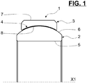
- a bearing 1 of main axis X1 comprises an inner ring 2, an outer ring 3, and a bearing liner 4 disposed therebetween.
- the inner ring 2 comprises a cylindrical bore 5, and a convex outer surface 6 of spherical shape.
- the inner ring is advantageously formed of a bearing steel, for example AMS5630.
- outer ring 3 is concentrically positioned with respect to inner ring 2.
- Outer ring 3 comprises a cylindrical outer surface 7, and a concave inner surface 8 of spherical shape.
- Inner surface 8 and outer surface 6 of outer ring 3 and inner ring 2, respectively, are of corresponding shapes to permit a relative motion between them.
- the inner ring 2 may be a movable ring, and the outer ring 3 may be a stationary ring.
- the inner ring 2 may be a stationary ring, and the outer ring 3 may be a movable ring.
- the inner ring 2 may consist in a journal.
- the outer ring 3 may consist in a stationary housing.
- the bearing liner 4 is radially interposed between the inner surface 8 of outer ring 3 and the outer surface 6 of inner ring 2.
- the bearing liner 4 is further detailed in Figure 2 .
- the bearing liner 4 comprises a first fabric 9, and a second fabric 10.
- First fabric 9 has a fibre sheet 11 pre-impregnated with a binder 12.
- the binder 12 comprises a resin, and preferably a phenolic resin.
- Second fabric 10 has a bearing element contact surface 13 with lubricating fibres 14, and structural fibres 15 supporting the said bearing element contact surface 13.
- the lubricating fibres comprise PTFE.
- the structural fibres comprise from 10 to 30 wt.% glass and/or carbon and/or polyester and/or aramid, and from 70 to 90 wt.% PTFE.
- Second fabric 10 is impregnated with binder 12 of first fabric 9.
- the bearing liner 4 is fixed to the outer surface 6 of inner ring 2, the bearing element contact surface 13 being in sliding contact with the inner surface 8 of outer ring 3.
- the bearing liner 4 may be fixed to the inner surface 8 of outer ring 3, the bearing element contact surface 13 being in sliding contact with the outer surface 6 of inner ring 2.
- Such a self-lubricated bearing liner 4 permits a reduced wear rate during the service life of a bearing 1.
- the said fibre sheet 11 and binder 12 incorporate conductive fillers.
- First fabric 9 is then electrically conductive.
- the resin binder 12 of first fabric 9 also impregnates the second fabric 10, and then said second fabric 10 is also electrically conductive.
- Conductive fillers comprise graphite fillers and/or metallic fillers such as copper or silver.
- the binder comprises at least 2 wt.% of graphite fillers to ensure efficient electrical conductivity.
- the bearing liner 4 permits the current to pass.
- the bearing 1 is then electrically conductive between the inner and outer rings 2, 3 through the outer and inner surfaces 6, 8, respectively, and the bearing liner 4.
- a method of manufacturing such a self-lubricated and electrically conductive bearing liner 4 comprises the step of providing the first fabric 9 comprising a fiber sheet 11 pre-impregnated with a binder 12, said fiber sheet 11 and binder 12 incorporating conductive fillers.
- the method comprises the step of providing the second fabric 10 comprising a bearing element contact surface 13 with lubricating fibres 14, and structural fibres 15 supporting the bearing element contact surface.
- the method comprises the final step of contacting and compressing together the first and second fabrics 9, 10 at an elevated temperature such as at least some of the binder 12 in the first fabric 9 transfers to the second fabric 10 and impregnates said second fabric 10.
- the binder-impregnated and electrically conductive first fabric 9 is advantageously pressed against the side of second fabric 10 with structural fibres 15, i.e. the side opposite the bearing element surface 13.
- the compressing is carried out at an elevated temperature, for example 160-180°C, to facilitate the amount of binder 12 that is transferred to, and impregnates, the second fabric 10.
- the bearing 1 illustrated in Figure 1 is a plain bearing.
- the bearing 1 is suitable for aerospace applications. Aerospace bearings operate under particularly arduous conditions, and may therefore fail relatively rapidly. As a result, aircraft maintenance guidelines enforce frequent inspection intervals.
- the mean time between replacement of the aerospace bearing 1 may be increased.
Abstract
The invention relates to a bearing liner (4) comprising a first fabric (9) having a fibre sheet (11) pre-impregnated with a binder (12), and a second fabric (10) impregnated with said binder (12), and having a bearing element contact surface (13) with lubricating fibres (14), and structural fibres (15) supporting the bearing element contact surface (13). The said fibre sheet (11) and binder (12) incorporate conductive fillers.
Description
- The present invention relates generally to the field of bearings, and in particular to an improved bearing liner and a bearing containing the same. The bearing liner has a low rate of wear in use, is electrically conductive, and may be used in a number of applications, for example aerospace applications.
- Bearings are devices that permit constrained relative motion between two parts. A plain bearing is the simplest type of bearing, comprising just a bearing surface and no rolling elements. Therefore the journal, i.e. the part of the shaft in contact with the bearing, slides over the bearing surface. The simplest example of a plain bearing is a shaft rotating in a hole. Two-piece plain bearings, known as full bearings in industrial machinery, are commonly used for larger diameters, such as crankshaft bearings. Self-lubricating plain bearings have a lubricant contained within the bearing walls. The lubricant is typically an integral element of the bearing material and remains part of the bearing's makeup for its useful life without the need of outside maintenance.
- Plain bearings often contain a liner between the bearing surfaces to reduce friction. Typical prior art fabric liners used in self-lubricating bearings comprise a woven fabric combined with a binder to form composite material that can be affixed to bearing surfaces. The fabric component of the composite consists of a top surface of lubricating yarns (typically PTFE fibres) which degrade through motion at the working surface and provide the bearing with lubricant, and structural yarns (typically glass fibers) which help retain the lubricating yarns and provide the composite with its structural integrity.
- Examples of bearing liners and their manufacturing processes are described in
EP-A1-2 955 400 . Fabric liners are laminated with a fibre sheet pre-impregnated with a resin binder. The resulting laminate is then compressed at an elevated temperature so that the binder bled though to impregnate the fabric. - It could be a great interest to improve such composite bearing liner enabling a wider use of plain bearings containing the same.
- The present invention provides a bearing liner comprising a first fabric having a fibre sheet pre-impregnated with a binder. The bearing liner further comprises a second fabric impregnated with said binder, and having a bearing element contact surface with lubricating fibres, and structural fibres supporting the bearing element contact surface.
- According to the invention, the said fibre sheet and binder incorporate conductive fillers.
- Thanks to the invention, the bearing liner is electrically conductive. Conductive fillers of fibre sheet are impregnated with a binder that also comprises conductive fillers. The electric current can pass through the liner. In some applications, for example aircraft landing gears, it is not necessary to provide additional electrically conductive paths. The invention permits to reduce the number of parts in certain applications, and then inducing cost and manufacturing saves, and can be used in particular applications requiring electrically conductive parts.
- The electrically conductive bearing liner is also self-lubricating to increase the working lifetime of a bearing.
- According to further aspects of the invention which are advantageous but not compulsory, such a bearing liner may incorporate one or several of the following features:
- Conductive fillers comprise graphite fillers and/or carbon fillers and/or metallic fillers such as copper or silver.
- The binder comprises at least 2 wt.% of graphite fillers.
- The binder comprises a resin, preferably a phenolic resin.
- The lubricating fibres comprise PTFE.
- The structural fibres comprise from 10 to 30 wt.% glass and/or carbon and/or polyester and/or aramid, and from 70 to 90 wt.% PTFE.
- In a further aspect, the invention also provides a bearing comprising an inner ring, an outer ring, and a bearing liner herein disposed therebetween and according to any of the preceding embodiments.
- According to further aspects of the invention which are advantageous but not compulsory, such a bearing may incorporate one or several of the following features:
- The bearing liner is fixed to an inner surface of outer ring, the bearing element surface being in contact with an outer surface of inner ring.
- The bearing liner is fixed to an outer surface of inner ring, the bearing element surface being in contact with an inner surface of outer ring.
- The inner ring has a convex outer surface, and the outer ring has a concave inner surface.
- The outer ring has a convex inner surface, and the inner ring has a concave outer surface.
- At least one of the rings is formed of a bearing steel, for example AMS 5630 or AMS 5643.
- The inner ring is a rotating journal.
- The outer ring is a fixed housing.
- The bearing is a plain bearing.
- In a further aspect, the invention provides a method of manufacturing a bearing liner according to any of the preceding embodiments, the method comprising the steps of:
- (a) Providing a first fabric comprising a fiber sheet pre-impregnated with a binder, said fiber sheet and binder incorporating conductive fillers,
- (b) Providing a second fabric comprising a bearing element contact surface with lubricating fibres, and structural fibres supporting the bearing element contact surface, and
- (c) Contacting and compressing together the first and second fabrics at an elevated temperature such as at least some of the binder in the first fabric transfers to the second fabric and impregnates said second fabric.
- In the contacting and compressing step, the binder-impregnated and electrically conductive first fabric is advantageously pressed against the side of second fabric with structural fibres, i.e. the side opposite the bearing element surface.
- The method permits to combine both fabrics to form an integral bearing liner. The electrically conductive binder of first fabric impregnates the second fabric with self-lubricating and structural fibres. The second fabric is then electrically conductive.
- The compressing is carried out at an elevated temperature, for example 160-180°C. The temperature used will depend on the nature of binder material. The elevated temperature facilitates the amount of binder that is transferred to, and impregnates, the second fabric. The first and/or second fabric(s) is/are typically woven.
- The invention will now be explained in correspondence with the annexed figures, as illustrative example, without restricting the object of the invention. In the annexed figures:
-
Figure 1 is a half-axial section of a bearing comprising a bearing liner according to the invention; and -
Figure 2 is a schematic bearing liner according to the invention. - Referring to
Figure 1 , abearing 1 of main axis X1 comprises aninner ring 2, anouter ring 3, and abearing liner 4 disposed therebetween. - The
inner ring 2 comprises acylindrical bore 5, and a convexouter surface 6 of spherical shape. The inner ring is advantageously formed of a bearing steel, for example AMS5630. - The
outer ring 3 is concentrically positioned with respect toinner ring 2.Outer ring 3 comprises a cylindricalouter surface 7, and a concaveinner surface 8 of spherical shape.Inner surface 8 andouter surface 6 ofouter ring 3 andinner ring 2, respectively, are of corresponding shapes to permit a relative motion between them. - The
inner ring 2 may be a movable ring, and theouter ring 3 may be a stationary ring. Alternatively, theinner ring 2 may be a stationary ring, and theouter ring 3 may be a movable ring. - Alternatively, the
inner ring 2 may consist in a journal. Alternatively, theouter ring 3 may consist in a stationary housing. - The
bearing liner 4 is radially interposed between theinner surface 8 ofouter ring 3 and theouter surface 6 ofinner ring 2. Thebearing liner 4 is further detailed inFigure 2 . - The
bearing liner 4 comprises afirst fabric 9, and asecond fabric 10. -
First fabric 9 has afibre sheet 11 pre-impregnated with abinder 12. Advantageously, thebinder 12 comprises a resin, and preferably a phenolic resin. -
Second fabric 10 has a bearingelement contact surface 13 withlubricating fibres 14, andstructural fibres 15 supporting the said bearingelement contact surface 13. Advantageously, the lubricating fibres comprise PTFE. Advantageously, the structural fibres comprise from 10 to 30 wt.% glass and/or carbon and/or polyester and/or aramid, and from 70 to 90 wt.% PTFE.Second fabric 10 is impregnated withbinder 12 offirst fabric 9. - In the embodiment of
Figure 2 , thebearing liner 4 is fixed to theouter surface 6 ofinner ring 2, the bearingelement contact surface 13 being in sliding contact with theinner surface 8 ofouter ring 3. Alternatively, thebearing liner 4 may be fixed to theinner surface 8 ofouter ring 3, the bearingelement contact surface 13 being in sliding contact with theouter surface 6 ofinner ring 2. - Such a self-lubricated
bearing liner 4 permits a reduced wear rate during the service life of abearing 1. - According to the invention, the said
fibre sheet 11 andbinder 12 incorporate conductive fillers. -
First fabric 9 is then electrically conductive. Theresin binder 12 offirst fabric 9 also impregnates thesecond fabric 10, and then saidsecond fabric 10 is also electrically conductive. - Conductive fillers comprise graphite fillers and/or metallic fillers such as copper or silver. Advantageously, the binder comprises at least 2 wt.% of graphite fillers to ensure efficient electrical conductivity.
- The
bearing liner 4 permits the current to pass. Thebearing 1 is then electrically conductive between the inner andouter rings inner surfaces bearing liner 4. - A method of manufacturing such a self-lubricated and electrically
conductive bearing liner 4 comprises the step of providing thefirst fabric 9 comprising afiber sheet 11 pre-impregnated with abinder 12, saidfiber sheet 11 andbinder 12 incorporating conductive fillers. - Then the method comprises the step of providing the
second fabric 10 comprising a bearingelement contact surface 13 withlubricating fibres 14, andstructural fibres 15 supporting the bearing element contact surface. - The method comprises the final step of contacting and compressing together the first and
second fabrics binder 12 in thefirst fabric 9 transfers to thesecond fabric 10 and impregnates saidsecond fabric 10. - In the contacting and compressing step, the binder-impregnated and electrically conductive
first fabric 9 is advantageously pressed against the side ofsecond fabric 10 withstructural fibres 15, i.e. the side opposite the bearingelement surface 13. - The compressing is carried out at an elevated temperature, for example 160-180°C, to facilitate the amount of
binder 12 that is transferred to, and impregnates, thesecond fabric 10. - The
bearing 1 illustrated inFigure 1 is a plain bearing. Advantageously, thebearing 1 is suitable for aerospace applications. Aerospace bearings operate under particularly arduous conditions, and may therefore fail relatively rapidly. As a result, aircraft maintenance guidelines enforce frequent inspection intervals. Advantageously, in view of the low wear rate of thebearing liner 4 according to the present invention, the mean time between replacement of theaerospace bearing 1 may be increased. - Representative, non-limiting examples of the present invention were described above in details with reference to the attached drawings. This detailed description is merely intended to teach a person of skill in the art further details for practicing preferred aspects of the present teachings and is not intended to limit the scope of the invention. Furthermore, each of the additional features and teachings disclosed above may be utilized separately or in conjunction with other features and teachings to provide improved bearing liner and bearing.
- Moreover, various features of the above-described representative examples, as well as the various independent and dependant claims below, may be combined in ways that are not specifically and explicitly enumerated in order to provide additional useful embodiments of the present teachings.
Claims (8)
- Bearing liner (4) comprising:- a first fabric (9) having a fibre sheet (11) pre-impregnated with a binder (12), and- a second fabric (10) impregnated with said binder (12), and having a bearing element contact surface (13) with lubricating fibres (14), and structural fibres (15) supporting the bearing element contact surface (13),
characterized in that the said fibre sheet (11) and binder (12) incorporate conductive fillers. - Bearing liner according to claim 1, wherein conductive fillers comprise graphite fillers and/or metallic fillers and/or carbon fillers.
- Bearing liner according to claim 2, wherein the binder (12) comprises at least 2 wt.% of graphite fillers.
- Bearing liner according to any of the preceding claims, wherein the binder (12) comprises a resin.
- Bearing liner according to any of the preceding claims, wherein the lubricating fibres (14) comprise PTFE.
- Bearing liner according to any of the preceding claims, wherein the structural fibres (15) comprise from 10 to 30 wt.% glass and/or carbon and/or polyester and/or aramid, and from 70 to 90 wt.% PTFE.
- Bearing comprising an inner ring (2), an outer ring (3), and a bearing liner (4) herein disposed therebetween and according to any of the preceding claims.
- Method of manufacturing a bearing liner (4) according to any of the claims 1 to 6, and comprising the steps of:(a) Providing the first fabric (9) comprising a fiber sheet (11) pre-impregnated with a binder (12), said fiber sheet (11) and binder (12) incorporating conductive fillers,(b) Providing the second fabric (10) comprising a bearing element contact surface (13) with lubricating fibres (14), and structural fibres (15) supporting the bearing element contact surface (13), and(c) Contacting and compressing together the first and second fabrics (9, 10) at an elevated temperature such as at least some of the binder (12) in the first fabric (9) transfers to the second fabric (10) and impregnates said second fabric (10).
Priority Applications (3)
| Application Number | Priority Date | Filing Date | Title |
|---|---|---|---|
| EP19175443.1A EP3742013A1 (en) | 2019-05-20 | 2019-05-20 | Electrically conductive and self-lubricating bearing liner, bearing containing the same, and method of manufacturing such a bearing liner |
| US16/871,924 US20200370597A1 (en) | 2019-05-20 | 2020-05-11 | Electrically conductive and self-lubricating bearing liner, bearing containing the same, and method of manufacturing such a bearing liner |
| CN202010419711.8A CN111963568A (en) | 2019-05-20 | 2020-05-18 | Electrically conductive and self-lubricating bearing bushing, bearing comprising same and method of manufacturing same |
Applications Claiming Priority (1)
| Application Number | Priority Date | Filing Date | Title |
|---|---|---|---|
| EP19175443.1A EP3742013A1 (en) | 2019-05-20 | 2019-05-20 | Electrically conductive and self-lubricating bearing liner, bearing containing the same, and method of manufacturing such a bearing liner |
Publications (1)
| Publication Number | Publication Date |
|---|---|
| EP3742013A1 true EP3742013A1 (en) | 2020-11-25 |
Family
ID=66625114
Family Applications (1)
| Application Number | Title | Priority Date | Filing Date |
|---|---|---|---|
| EP19175443.1A Withdrawn EP3742013A1 (en) | 2019-05-20 | 2019-05-20 | Electrically conductive and self-lubricating bearing liner, bearing containing the same, and method of manufacturing such a bearing liner |
Country Status (3)
| Country | Link |
|---|---|
| US (1) | US20200370597A1 (en) |
| EP (1) | EP3742013A1 (en) |
| CN (1) | CN111963568A (en) |
Families Citing this family (4)
| Publication number | Priority date | Publication date | Assignee | Title |
|---|---|---|---|---|
| US11149795B2 (en) * | 2019-03-01 | 2021-10-19 | Pratt & Whitney Canada Corp. | Turbine engine bearing used as a static electricity leak path |
| EP3751161B1 (en) * | 2019-06-14 | 2023-09-27 | Safran Landing Systems UK Ltd | Self-lubricating bush assembly |
| CN114704552B (en) * | 2022-03-30 | 2023-06-20 | 深圳大学 | Current-carrying solid film lubrication bearing and friction control method thereof |
| DE102022121689A1 (en) * | 2022-08-26 | 2024-02-29 | Federal-Mogul Wiesbaden Gmbh | Conductive self-lubricating sliding element |
Citations (4)
| Publication number | Priority date | Publication date | Assignee | Title |
|---|---|---|---|---|
| US5908001A (en) * | 1997-09-09 | 1999-06-01 | Zeftek, Inc. | Center plate assembly bearing liner |
| EP2759728A1 (en) * | 2011-09-22 | 2014-07-30 | NTN Corporation | Sliding bearing and image formation device |
| EP2955400A1 (en) | 2014-06-12 | 2015-12-16 | Aktiebolaget SKF | Bearing liner |
| DE102016115619A1 (en) * | 2016-08-23 | 2018-03-01 | Federal-Mogul Deva Gmbh | Slide pin and plug-in coupling with sliding pin |
-
2019
- 2019-05-20 EP EP19175443.1A patent/EP3742013A1/en not_active Withdrawn
-
2020
- 2020-05-11 US US16/871,924 patent/US20200370597A1/en not_active Abandoned
- 2020-05-18 CN CN202010419711.8A patent/CN111963568A/en active Pending
Patent Citations (4)
| Publication number | Priority date | Publication date | Assignee | Title |
|---|---|---|---|---|
| US5908001A (en) * | 1997-09-09 | 1999-06-01 | Zeftek, Inc. | Center plate assembly bearing liner |
| EP2759728A1 (en) * | 2011-09-22 | 2014-07-30 | NTN Corporation | Sliding bearing and image formation device |
| EP2955400A1 (en) | 2014-06-12 | 2015-12-16 | Aktiebolaget SKF | Bearing liner |
| DE102016115619A1 (en) * | 2016-08-23 | 2018-03-01 | Federal-Mogul Deva Gmbh | Slide pin and plug-in coupling with sliding pin |
Also Published As
| Publication number | Publication date |
|---|---|
| US20200370597A1 (en) | 2020-11-26 |
| CN111963568A (en) | 2020-11-20 |
Similar Documents
| Publication | Publication Date | Title |
|---|---|---|
| EP3742013A1 (en) | Electrically conductive and self-lubricating bearing liner, bearing containing the same, and method of manufacturing such a bearing liner | |
| EP0962676A2 (en) | Bearing assembly with spherical bearing surfaces | |
| EP2955400B1 (en) | Bearing liner | |
| US20170146058A1 (en) | Maintenance-free bearing with tolerance compensation properties against wear and misalignment | |
| US2219054A (en) | Bearing | |
| US11473626B2 (en) | Bearing system with self-lubrication features, seals, grooves and slots for maintenance-free operation | |
| US10501172B2 (en) | Aircraft landing gear assembly | |
| EP0307112A2 (en) | Braided bearing and method for making a braided bearing | |
| EP2955399A1 (en) | Plain bearing | |
| EP2955401B1 (en) | Plain bearing | |
| EP0969217A2 (en) | Composite spherical bearing and method of producing same | |
| JP5691553B2 (en) | Pressure-resistant sliding member and brake pad | |
| US20180100542A1 (en) | Spacer device, toroidal roller bearing & method | |
| US2464492A (en) | Self-aligning bearing | |
| CN201802762U (en) | Self-lubricating oscillating bearing with two half-outer ring integrated structure | |
| US4837908A (en) | Roll assembly for fiber drafting machine | |
| CN111981037A (en) | Bushing with improved wear resistance and sliding bearing comprising such a bushing | |
| CN112963443A (en) | Titanium alloy knuckle bearing friction pair, manufacturing method and lubricating use method | |
| RU112303U1 (en) | BEARING SLIDING MODULE PINUS (OPTIONS) | |
| CN207514077U (en) | A kind of pad bearing of non-cylindrical fibre | |
| CN112178051A (en) | Self-lubricating joint bearing | |
| US9810262B2 (en) | Spacer device, toroidal roller bearing and method | |
| CN219452803U (en) | Cylindrical drum structure | |
| KR101832066B1 (en) | Apparatus for manufacturing bushing with double connecting structure | |
| CN111810537A (en) | Sliding bearing and use thereof |
Legal Events
| Date | Code | Title | Description |
|---|---|---|---|
| PUAI | Public reference made under article 153(3) epc to a published international application that has entered the european phase |
Free format text: ORIGINAL CODE: 0009012 |
|
| STAA | Information on the status of an ep patent application or granted ep patent |
Free format text: STATUS: THE APPLICATION HAS BEEN PUBLISHED |
|
| AK | Designated contracting states |
Kind code of ref document: A1 Designated state(s): AL AT BE BG CH CY CZ DE DK EE ES FI FR GB GR HR HU IE IS IT LI LT LU LV MC MK MT NL NO PL PT RO RS SE SI SK SM TR |
|
| AX | Request for extension of the european patent |
Extension state: BA ME |
|
| RAP3 | Party data changed (applicant data changed or rights of an application transferred) |
Owner name: AKTIEBOLAGET SKF |
|
| STAA | Information on the status of an ep patent application or granted ep patent |
Free format text: STATUS: THE APPLICATION IS DEEMED TO BE WITHDRAWN |
|
| 18D | Application deemed to be withdrawn |
Effective date: 20210526 |