EP2759728A1 - Sliding bearing and image formation device - Google Patents
Sliding bearing and image formation device Download PDFInfo
- Publication number
- EP2759728A1 EP2759728A1 EP12832840.8A EP12832840A EP2759728A1 EP 2759728 A1 EP2759728 A1 EP 2759728A1 EP 12832840 A EP12832840 A EP 12832840A EP 2759728 A1 EP2759728 A1 EP 2759728A1
- Authority
- EP
- European Patent Office
- Prior art keywords
- curved surface
- sliding bearing
- resin
- outer ring
- inner ring
- Prior art date
- Legal status (The legal status is an assumption and is not a legal conclusion. Google has not performed a legal analysis and makes no representation as to the accuracy of the status listed.)
- Withdrawn
Links
- 230000015572 biosynthetic process Effects 0.000 title description 5
- 229910052751 metal Inorganic materials 0.000 claims abstract description 67
- 239000002184 metal Substances 0.000 claims abstract description 67
- 239000011342 resin composition Substances 0.000 claims abstract description 66
- 230000003746 surface roughness Effects 0.000 claims abstract description 23
- 230000013011 mating Effects 0.000 claims abstract description 9
- 229920005989 resin Polymers 0.000 claims description 199
- 239000011347 resin Substances 0.000 claims description 199
- 239000004519 grease Substances 0.000 claims description 88
- 235000013305 food Nutrition 0.000 claims description 74
- 239000000314 lubricant Substances 0.000 claims description 56
- OKTJSMMVPCPJKN-UHFFFAOYSA-N Carbon Chemical compound [C] OKTJSMMVPCPJKN-UHFFFAOYSA-N 0.000 claims description 41
- 239000004734 Polyphenylene sulfide Substances 0.000 claims description 21
- 229920000069 polyphenylene sulfide Polymers 0.000 claims description 21
- 229910052799 carbon Inorganic materials 0.000 claims description 20
- 229920001343 polytetrafluoroethylene Polymers 0.000 claims description 18
- 239000004810 polytetrafluoroethylene Substances 0.000 claims description 18
- -1 polytetrafluoroethylene Polymers 0.000 claims description 17
- 229920003002 synthetic resin Polymers 0.000 claims description 17
- 239000000057 synthetic resin Substances 0.000 claims description 17
- 229910002804 graphite Inorganic materials 0.000 claims description 16
- 239000010439 graphite Substances 0.000 claims description 16
- 239000004696 Poly ether ether ketone Substances 0.000 claims description 15
- 229920002530 polyetherether ketone Polymers 0.000 claims description 15
- 238000001746 injection moulding Methods 0.000 claims description 12
- 229920001643 poly(ether ketone) Polymers 0.000 claims description 12
- 229910001220 stainless steel Inorganic materials 0.000 claims description 12
- 239000010935 stainless steel Substances 0.000 claims description 12
- 238000012546 transfer Methods 0.000 claims description 12
- 229920000049 Carbon (fiber) Polymers 0.000 claims description 11
- 229910000831 Steel Inorganic materials 0.000 claims description 11
- 239000004760 aramid Substances 0.000 claims description 11
- 239000004917 carbon fiber Substances 0.000 claims description 11
- 239000010959 steel Substances 0.000 claims description 11
- 229920006231 aramid fiber Polymers 0.000 claims description 10
- WHXSMMKQMYFTQS-UHFFFAOYSA-N Lithium Chemical compound [Li] WHXSMMKQMYFTQS-UHFFFAOYSA-N 0.000 claims description 9
- 229910052744 lithium Inorganic materials 0.000 claims description 9
- 239000010445 mica Substances 0.000 claims description 8
- 229910052618 mica group Inorganic materials 0.000 claims description 8
- 229920002312 polyamide-imide Polymers 0.000 claims description 8
- 239000000454 talc Substances 0.000 claims description 8
- 229910052623 talc Inorganic materials 0.000 claims description 8
- 239000004962 Polyamide-imide Substances 0.000 claims description 7
- XSQUKJJJFZCRTK-UHFFFAOYSA-N Urea Chemical compound NC(N)=O XSQUKJJJFZCRTK-UHFFFAOYSA-N 0.000 claims description 7
- 239000004202 carbamide Substances 0.000 claims description 7
- 229910052804 chromium Inorganic materials 0.000 claims description 7
- 239000011651 chromium Substances 0.000 claims description 7
- 238000007373 indentation Methods 0.000 claims description 6
- 229910000975 Carbon steel Inorganic materials 0.000 claims description 5
- 239000010962 carbon steel Substances 0.000 claims description 5
- VNTLIPZTSJSULJ-UHFFFAOYSA-N chromium molybdenum Chemical compound [Cr].[Mo] VNTLIPZTSJSULJ-UHFFFAOYSA-N 0.000 claims description 5
- 229930182556 Polyacetal Natural products 0.000 claims description 3
- 229920006324 polyoxymethylene Polymers 0.000 claims description 3
- 150000002576 ketones Chemical class 0.000 claims description 2
- 229920006122 polyamide resin Polymers 0.000 claims description 2
- 229920013716 polyethylene resin Polymers 0.000 claims description 2
- 239000009719 polyimide resin Substances 0.000 claims 1
- 229920006259 thermoplastic polyimide Polymers 0.000 claims 1
- 239000000463 material Substances 0.000 abstract description 32
- 238000004519 manufacturing process Methods 0.000 abstract description 30
- 239000003921 oil Substances 0.000 description 45
- 235000019198 oils Nutrition 0.000 description 45
- 238000012360 testing method Methods 0.000 description 40
- 239000002199 base oil Substances 0.000 description 21
- 239000010687 lubricating oil Substances 0.000 description 18
- 230000002829 reductive effect Effects 0.000 description 17
- 230000000694 effects Effects 0.000 description 16
- 239000000843 powder Substances 0.000 description 16
- 239000004952 Polyamide Substances 0.000 description 15
- 229920002647 polyamide Polymers 0.000 description 15
- 238000000034 method Methods 0.000 description 13
- 239000012779 reinforcing material Substances 0.000 description 13
- 239000007787 solid Substances 0.000 description 13
- 239000010696 ester oil Substances 0.000 description 12
- 239000004698 Polyethylene Substances 0.000 description 11
- 239000004642 Polyimide Substances 0.000 description 11
- 239000000203 mixture Substances 0.000 description 11
- 229920000573 polyethylene Polymers 0.000 description 11
- 229920001721 polyimide Polymers 0.000 description 11
- 230000009467 reduction Effects 0.000 description 11
- 239000000654 additive Substances 0.000 description 10
- 238000000465 moulding Methods 0.000 description 10
- 230000000052 comparative effect Effects 0.000 description 9
- 239000003273 ketjen black Substances 0.000 description 9
- 229920002545 silicone oil Polymers 0.000 description 9
- VTYYLEPIZMXCLO-UHFFFAOYSA-L Calcium carbonate Chemical compound [Ca+2].[O-]C([O-])=O VTYYLEPIZMXCLO-UHFFFAOYSA-L 0.000 description 8
- 239000000344 soap Substances 0.000 description 8
- 239000000126 substance Substances 0.000 description 8
- 230000000996 additive effect Effects 0.000 description 7
- 229910052782 aluminium Inorganic materials 0.000 description 7
- XAGFODPZIPBFFR-UHFFFAOYSA-N aluminium Chemical compound [Al] XAGFODPZIPBFFR-UHFFFAOYSA-N 0.000 description 7
- 230000008569 process Effects 0.000 description 7
- 230000008093 supporting effect Effects 0.000 description 7
- 229920001169 thermoplastic Polymers 0.000 description 7
- 239000004416 thermosoftening plastic Substances 0.000 description 7
- 230000007423 decrease Effects 0.000 description 6
- 229940057995 liquid paraffin Drugs 0.000 description 6
- 238000012545 processing Methods 0.000 description 6
- XLYOFNOQVPJJNP-UHFFFAOYSA-N water Substances O XLYOFNOQVPJJNP-UHFFFAOYSA-N 0.000 description 6
- 239000005662 Paraffin oil Substances 0.000 description 5
- 150000001875 compounds Chemical class 0.000 description 5
- 229920001577 copolymer Polymers 0.000 description 5
- 235000013373 food additive Nutrition 0.000 description 5
- 230000009477 glass transition Effects 0.000 description 5
- 230000001976 improved effect Effects 0.000 description 5
- 238000002347 injection Methods 0.000 description 5
- 239000007924 injection Substances 0.000 description 5
- JEIPFZHSYJVQDO-UHFFFAOYSA-N iron(III) oxide Inorganic materials O=[Fe]O[Fe]=O JEIPFZHSYJVQDO-UHFFFAOYSA-N 0.000 description 5
- 238000002844 melting Methods 0.000 description 5
- 230000008018 melting Effects 0.000 description 5
- 231100000252 nontoxic Toxicity 0.000 description 5
- 230000003000 nontoxic effect Effects 0.000 description 5
- 229920013639 polyalphaolefin Polymers 0.000 description 5
- 229920001707 polybutylene terephthalate Polymers 0.000 description 5
- 229920000139 polyethylene terephthalate Polymers 0.000 description 5
- 239000005020 polyethylene terephthalate Substances 0.000 description 5
- 229920000642 polymer Polymers 0.000 description 5
- 238000005096 rolling process Methods 0.000 description 5
- 229920005992 thermoplastic resin Polymers 0.000 description 5
- 239000002562 thickening agent Substances 0.000 description 5
- 229910000838 Al alloy Inorganic materials 0.000 description 4
- 239000004215 Carbon black (E152) Substances 0.000 description 4
- 229910052791 calcium Inorganic materials 0.000 description 4
- 229910000019 calcium carbonate Inorganic materials 0.000 description 4
- 230000000368 destabilizing effect Effects 0.000 description 4
- 239000000835 fiber Substances 0.000 description 4
- 238000010304 firing Methods 0.000 description 4
- 229930195733 hydrocarbon Natural products 0.000 description 4
- 150000002430 hydrocarbons Chemical class 0.000 description 4
- 230000001050 lubricating effect Effects 0.000 description 4
- 238000003754 machining Methods 0.000 description 4
- 239000002480 mineral oil Substances 0.000 description 4
- 230000000116 mitigating effect Effects 0.000 description 4
- 238000002156 mixing Methods 0.000 description 4
- 230000036961 partial effect Effects 0.000 description 4
- 239000002245 particle Substances 0.000 description 4
- 239000002994 raw material Substances 0.000 description 4
- 230000003014 reinforcing effect Effects 0.000 description 4
- 239000012266 salt solution Substances 0.000 description 4
- PXHVJJICTQNCMI-UHFFFAOYSA-N Nickel Chemical compound [Ni] PXHVJJICTQNCMI-UHFFFAOYSA-N 0.000 description 3
- 229920000572 Nylon 6/12 Polymers 0.000 description 3
- 229920002396 Polyurea Polymers 0.000 description 3
- 229920004695 VICTREX™ PEEK Polymers 0.000 description 3
- 238000010521 absorption reaction Methods 0.000 description 3
- 239000010775 animal oil Substances 0.000 description 3
- 229920006167 biodegradable resin Polymers 0.000 description 3
- 230000008602 contraction Effects 0.000 description 3
- 238000010894 electron beam technology Methods 0.000 description 3
- RTZKZFJDLAIYFH-UHFFFAOYSA-N ether Substances CCOCC RTZKZFJDLAIYFH-UHFFFAOYSA-N 0.000 description 3
- 238000005461 lubrication Methods 0.000 description 3
- 235000010446 mineral oil Nutrition 0.000 description 3
- 238000012986 modification Methods 0.000 description 3
- 230000004048 modification Effects 0.000 description 3
- 125000001997 phenyl group Chemical group [H]C1=C([H])C([H])=C(*)C([H])=C1[H] 0.000 description 3
- 238000007747 plating Methods 0.000 description 3
- 239000011164 primary particle Substances 0.000 description 3
- 230000001737 promoting effect Effects 0.000 description 3
- 230000005855 radiation Effects 0.000 description 3
- 230000000087 stabilizing effect Effects 0.000 description 3
- 238000007669 thermal treatment Methods 0.000 description 3
- 235000015112 vegetable and seed oil Nutrition 0.000 description 3
- 239000008158 vegetable oil Substances 0.000 description 3
- 229910052582 BN Inorganic materials 0.000 description 2
- PZNSFCLAULLKQX-UHFFFAOYSA-N Boron nitride Chemical compound N#B PZNSFCLAULLKQX-UHFFFAOYSA-N 0.000 description 2
- OYPRJOBELJOOCE-UHFFFAOYSA-N Calcium Chemical compound [Ca] OYPRJOBELJOOCE-UHFFFAOYSA-N 0.000 description 2
- 229920005177 Duracon® POM Polymers 0.000 description 2
- 241000196324 Embryophyta Species 0.000 description 2
- XEEYBQQBJWHFJM-UHFFFAOYSA-N Iron Chemical compound [Fe] XEEYBQQBJWHFJM-UHFFFAOYSA-N 0.000 description 2
- UQSXHKLRYXJYBZ-UHFFFAOYSA-N Iron oxide Chemical compound [Fe]=O UQSXHKLRYXJYBZ-UHFFFAOYSA-N 0.000 description 2
- 229920003189 Nylon 4,6 Polymers 0.000 description 2
- 229910019142 PO4 Inorganic materials 0.000 description 2
- 241000282320 Panthera leo Species 0.000 description 2
- PPBRXRYQALVLMV-UHFFFAOYSA-N Styrene Chemical compound C=CC1=CC=CC=C1 PPBRXRYQALVLMV-UHFFFAOYSA-N 0.000 description 2
- QAOWNCQODCNURD-UHFFFAOYSA-N Sulfuric acid Chemical compound OS(O)(=O)=O QAOWNCQODCNURD-UHFFFAOYSA-N 0.000 description 2
- GWEVSGVZZGPLCZ-UHFFFAOYSA-N Titan oxide Chemical compound O=[Ti]=O GWEVSGVZZGPLCZ-UHFFFAOYSA-N 0.000 description 2
- XLOMVQKBTHCTTD-UHFFFAOYSA-N Zinc monoxide Chemical compound [Zn]=O XLOMVQKBTHCTTD-UHFFFAOYSA-N 0.000 description 2
- 230000002159 abnormal effect Effects 0.000 description 2
- 238000009825 accumulation Methods 0.000 description 2
- 229910045601 alloy Inorganic materials 0.000 description 2
- 239000000956 alloy Substances 0.000 description 2
- WERYXYBDKMZEQL-UHFFFAOYSA-N butane-1,4-diol Chemical compound OCCCCO WERYXYBDKMZEQL-UHFFFAOYSA-N 0.000 description 2
- 239000011575 calcium Substances 0.000 description 2
- 239000006229 carbon black Substances 0.000 description 2
- 239000003795 chemical substances by application Substances 0.000 description 2
- 230000000295 complement effect Effects 0.000 description 2
- 239000000470 constituent Substances 0.000 description 2
- 238000010276 construction Methods 0.000 description 2
- 238000011109 contamination Methods 0.000 description 2
- NJLLQSBAHIKGKF-UHFFFAOYSA-N dipotassium dioxido(oxo)titanium Chemical compound [K+].[K+].[O-][Ti]([O-])=O NJLLQSBAHIKGKF-UHFFFAOYSA-N 0.000 description 2
- 238000009826 distribution Methods 0.000 description 2
- 230000005489 elastic deformation Effects 0.000 description 2
- 229920000840 ethylene tetrafluoroethylene copolymer Polymers 0.000 description 2
- 230000001747 exhibiting effect Effects 0.000 description 2
- 125000003709 fluoroalkyl group Chemical group 0.000 description 2
- 239000002778 food additive Substances 0.000 description 2
- 238000000227 grinding Methods 0.000 description 2
- 230000006872 improvement Effects 0.000 description 2
- 239000012770 industrial material Substances 0.000 description 2
- 229910000734 martensite Inorganic materials 0.000 description 2
- 150000002739 metals Chemical class 0.000 description 2
- CWQXQMHSOZUFJS-UHFFFAOYSA-N molybdenum disulfide Chemical compound S=[Mo]=S CWQXQMHSOZUFJS-UHFFFAOYSA-N 0.000 description 2
- 229910052982 molybdenum disulfide Inorganic materials 0.000 description 2
- 244000045947 parasite Species 0.000 description 2
- 230000000149 penetrating effect Effects 0.000 description 2
- 239000010452 phosphate Substances 0.000 description 2
- NBIIXXVUZAFLBC-UHFFFAOYSA-K phosphate Chemical compound [O-]P([O-])([O-])=O NBIIXXVUZAFLBC-UHFFFAOYSA-K 0.000 description 2
- 229920006128 poly(nonamethylene terephthalamide) Polymers 0.000 description 2
- 229920001281 polyalkylene Polymers 0.000 description 2
- 229920001515 polyalkylene glycol Polymers 0.000 description 2
- 229920002961 polybutylene succinate Polymers 0.000 description 2
- 239000004631 polybutylene succinate Substances 0.000 description 2
- 238000010008 shearing Methods 0.000 description 2
- 238000009751 slip forming Methods 0.000 description 2
- KDYFGRWQOYBRFD-UHFFFAOYSA-N succinic acid Chemical compound OC(=O)CCC(O)=O KDYFGRWQOYBRFD-UHFFFAOYSA-N 0.000 description 2
- OGIDPMRJRNCKJF-UHFFFAOYSA-N titanium oxide Inorganic materials [Ti]=O OGIDPMRJRNCKJF-UHFFFAOYSA-N 0.000 description 2
- 239000003440 toxic substance Substances 0.000 description 2
- ITRNXVSDJBHYNJ-UHFFFAOYSA-N tungsten disulfide Chemical compound S=[W]=S ITRNXVSDJBHYNJ-UHFFFAOYSA-N 0.000 description 2
- 239000010456 wollastonite Substances 0.000 description 2
- 229910052882 wollastonite Inorganic materials 0.000 description 2
- XMKLTEGSALONPH-UHFFFAOYSA-N 1,2,4,5-tetrazinane-3,6-dione Chemical class O=C1NNC(=O)NN1 XMKLTEGSALONPH-UHFFFAOYSA-N 0.000 description 1
- JRHWHSJDIILJAT-UHFFFAOYSA-N 2-hydroxypentanoic acid Chemical compound CCCC(O)C(O)=O JRHWHSJDIILJAT-UHFFFAOYSA-N 0.000 description 1
- KXGFMDJXCMQABM-UHFFFAOYSA-N 2-methoxy-6-methylphenol Chemical compound [CH]OC1=CC=CC([CH])=C1O KXGFMDJXCMQABM-UHFFFAOYSA-N 0.000 description 1
- SJZRECIVHVDYJC-UHFFFAOYSA-N 4-hydroxybutyric acid Chemical compound OCCCC(O)=O SJZRECIVHVDYJC-UHFFFAOYSA-N 0.000 description 1
- 241000255789 Bombyx mori Species 0.000 description 1
- 229910001369 Brass Inorganic materials 0.000 description 1
- XMWRBQBLMFGWIX-UHFFFAOYSA-N C60 fullerene Chemical class C12=C3C(C4=C56)=C7C8=C5C5=C9C%10=C6C6=C4C1=C1C4=C6C6=C%10C%10=C9C9=C%11C5=C8C5=C8C7=C3C3=C7C2=C1C1=C2C4=C6C4=C%10C6=C9C9=C%11C5=C5C8=C3C3=C7C1=C1C2=C4C6=C2C9=C5C3=C12 XMWRBQBLMFGWIX-UHFFFAOYSA-N 0.000 description 1
- 101100175010 Caenorhabditis elegans gbf-1 gene Proteins 0.000 description 1
- 229910001018 Cast iron Inorganic materials 0.000 description 1
- VYZAMTAEIAYCRO-UHFFFAOYSA-N Chromium Chemical compound [Cr] VYZAMTAEIAYCRO-UHFFFAOYSA-N 0.000 description 1
- 241000252203 Clupea harengus Species 0.000 description 1
- 229920003656 Daiamid® Polymers 0.000 description 1
- 229920004466 Fluon® PCTFE Polymers 0.000 description 1
- PXGOKWXKJXAPGV-UHFFFAOYSA-N Fluorine Chemical compound FF PXGOKWXKJXAPGV-UHFFFAOYSA-N 0.000 description 1
- 241000282412 Homo Species 0.000 description 1
- DGAQECJNVWCQMB-PUAWFVPOSA-M Ilexoside XXIX Chemical compound C[C@@H]1CC[C@@]2(CC[C@@]3(C(=CC[C@H]4[C@]3(CC[C@@H]5[C@@]4(CC[C@@H](C5(C)C)OS(=O)(=O)[O-])C)C)[C@@H]2[C@]1(C)O)C)C(=O)O[C@H]6[C@@H]([C@H]([C@@H]([C@H](O6)CO)O)O)O.[Na+] DGAQECJNVWCQMB-PUAWFVPOSA-M 0.000 description 1
- 229920000271 Kevlar® Polymers 0.000 description 1
- AFCARXCZXQIEQB-UHFFFAOYSA-N N-[3-oxo-3-(2,4,6,7-tetrahydrotriazolo[4,5-c]pyridin-5-yl)propyl]-2-[[3-(trifluoromethoxy)phenyl]methylamino]pyrimidine-5-carboxamide Chemical compound O=C(CCNC(=O)C=1C=NC(=NC=1)NCC1=CC(=CC=C1)OC(F)(F)F)N1CC2=C(CC1)NN=N2 AFCARXCZXQIEQB-UHFFFAOYSA-N 0.000 description 1
- 229920002292 Nylon 6 Polymers 0.000 description 1
- 229920002302 Nylon 6,6 Polymers 0.000 description 1
- BPQQTUXANYXVAA-UHFFFAOYSA-N Orthosilicate Chemical compound [O-][Si]([O-])([O-])[O-] BPQQTUXANYXVAA-UHFFFAOYSA-N 0.000 description 1
- 235000019483 Peanut oil Nutrition 0.000 description 1
- NBIIXXVUZAFLBC-UHFFFAOYSA-L Phosphate ion(2-) Chemical compound OP([O-])([O-])=O NBIIXXVUZAFLBC-UHFFFAOYSA-L 0.000 description 1
- 235000008331 Pinus X rigitaeda Nutrition 0.000 description 1
- 235000011613 Pinus brutia Nutrition 0.000 description 1
- 241000018646 Pinus brutia Species 0.000 description 1
- 229920008285 Poly(ether ketone) PEK Polymers 0.000 description 1
- 239000002202 Polyethylene glycol Substances 0.000 description 1
- 229920000954 Polyglycolide Polymers 0.000 description 1
- 235000019484 Rapeseed oil Nutrition 0.000 description 1
- 241001125046 Sardina pilchardus Species 0.000 description 1
- BLRPTPMANUNPDV-UHFFFAOYSA-N Silane Chemical compound [SiH4] BLRPTPMANUNPDV-UHFFFAOYSA-N 0.000 description 1
- 239000006087 Silane Coupling Agent Substances 0.000 description 1
- 229920001494 Technora Polymers 0.000 description 1
- 229920006362 Teflon® Polymers 0.000 description 1
- 229920000561 Twaron Polymers 0.000 description 1
- 229920003521 Ultramid® A Polymers 0.000 description 1
- 229920003801 Ultramid® B Polymers 0.000 description 1
- 229920003469 Ultramid® T Polymers 0.000 description 1
- 229920006102 Zytel® Polymers 0.000 description 1
- 238000005299 abrasion Methods 0.000 description 1
- 239000002250 absorbent Substances 0.000 description 1
- 239000006230 acetylene black Substances 0.000 description 1
- 239000004840 adhesive resin Substances 0.000 description 1
- 229920006223 adhesive resin Polymers 0.000 description 1
- 150000001336 alkenes Chemical class 0.000 description 1
- 150000004996 alkyl benzenes Chemical class 0.000 description 1
- OJMOMXZKOWKUTA-UHFFFAOYSA-N aluminum;borate Chemical compound [Al+3].[O-]B([O-])[O-] OJMOMXZKOWKUTA-UHFFFAOYSA-N 0.000 description 1
- 238000000137 annealing Methods 0.000 description 1
- 150000004945 aromatic hydrocarbons Chemical class 0.000 description 1
- 229920003235 aromatic polyamide Polymers 0.000 description 1
- 125000003118 aryl group Chemical group 0.000 description 1
- 125000004429 atom Chemical group 0.000 description 1
- QVGXLLKOCUKJST-UHFFFAOYSA-N atomic oxygen Chemical compound [O] QVGXLLKOCUKJST-UHFFFAOYSA-N 0.000 description 1
- 235000015278 beef Nutrition 0.000 description 1
- 238000005452 bending Methods 0.000 description 1
- CCDWGDHTPAJHOA-UHFFFAOYSA-N benzylsilicon Chemical compound [Si]CC1=CC=CC=C1 CCDWGDHTPAJHOA-UHFFFAOYSA-N 0.000 description 1
- 230000033228 biological regulation Effects 0.000 description 1
- 229920001400 block copolymer Polymers 0.000 description 1
- 239000010951 brass Substances 0.000 description 1
- 239000010495 camellia oil Substances 0.000 description 1
- 229910021393 carbon nanotube Inorganic materials 0.000 description 1
- 239000002041 carbon nanotube Substances 0.000 description 1
- 125000002915 carbonyl group Chemical group [*:2]C([*:1])=O 0.000 description 1
- 239000004359 castor oil Substances 0.000 description 1
- 235000019438 castor oil Nutrition 0.000 description 1
- 230000015556 catabolic process Effects 0.000 description 1
- 230000008859 change Effects 0.000 description 1
- 239000006231 channel black Substances 0.000 description 1
- 239000004927 clay Substances 0.000 description 1
- 238000004140 cleaning Methods 0.000 description 1
- 239000003086 colorant Substances 0.000 description 1
- 238000009841 combustion method Methods 0.000 description 1
- 238000013329 compounding Methods 0.000 description 1
- 238000005260 corrosion Methods 0.000 description 1
- 230000007797 corrosion Effects 0.000 description 1
- 229920006038 crystalline resin Polymers 0.000 description 1
- 230000003247 decreasing effect Effects 0.000 description 1
- 238000006731 degradation reaction Methods 0.000 description 1
- 150000005690 diesters Chemical class 0.000 description 1
- NBIIXXVUZAFLBC-UHFFFAOYSA-M dihydrogenphosphate Chemical compound OP(O)([O-])=O NBIIXXVUZAFLBC-UHFFFAOYSA-M 0.000 description 1
- 125000000118 dimethyl group Chemical group [H]C([H])([H])* 0.000 description 1
- 239000004205 dimethyl polysiloxane Substances 0.000 description 1
- 235000013870 dimethyl polysiloxane Nutrition 0.000 description 1
- 239000003651 drinking water Substances 0.000 description 1
- 235000020188 drinking water Nutrition 0.000 description 1
- 239000003814 drug Substances 0.000 description 1
- 229940079593 drug Drugs 0.000 description 1
- 239000000428 dust Substances 0.000 description 1
- 230000005611 electricity Effects 0.000 description 1
- 238000007720 emulsion polymerization reaction Methods 0.000 description 1
- 239000003822 epoxy resin Substances 0.000 description 1
- QHSJIZLJUFMIFP-UHFFFAOYSA-N ethene;1,1,2,2-tetrafluoroethene Chemical compound C=C.FC(F)=C(F)F QHSJIZLJUFMIFP-UHFFFAOYSA-N 0.000 description 1
- 125000001033 ether group Chemical group 0.000 description 1
- LYCAIKOWRPUZTN-UHFFFAOYSA-N ethylene glycol Natural products OCCO LYCAIKOWRPUZTN-UHFFFAOYSA-N 0.000 description 1
- 238000004880 explosion Methods 0.000 description 1
- 239000000945 filler Substances 0.000 description 1
- 229910052731 fluorine Inorganic materials 0.000 description 1
- 239000011737 fluorine Substances 0.000 description 1
- 238000009472 formulation Methods 0.000 description 1
- 229910003472 fullerene Inorganic materials 0.000 description 1
- 239000006232 furnace black Substances 0.000 description 1
- 108700039708 galantide Proteins 0.000 description 1
- 239000007789 gas Substances 0.000 description 1
- 239000011521 glass Substances 0.000 description 1
- 239000003365 glass fiber Substances 0.000 description 1
- ZEMPKEQAKRGZGQ-XOQCFJPHSA-N glycerol triricinoleate Natural products CCCCCC[C@@H](O)CC=CCCCCCCCC(=O)OC[C@@H](COC(=O)CCCCCCCC=CC[C@@H](O)CCCCCC)OC(=O)CCCCCCCC=CC[C@H](O)CCCCCC ZEMPKEQAKRGZGQ-XOQCFJPHSA-N 0.000 description 1
- PCHJSUWPFVWCPO-UHFFFAOYSA-N gold Chemical compound [Au] PCHJSUWPFVWCPO-UHFFFAOYSA-N 0.000 description 1
- 239000008187 granular material Substances 0.000 description 1
- 230000020169 heat generation Effects 0.000 description 1
- 229920006015 heat resistant resin Polymers 0.000 description 1
- 235000019514 herring Nutrition 0.000 description 1
- 229920001519 homopolymer Polymers 0.000 description 1
- WGCNASOHLSPBMP-UHFFFAOYSA-N hydroxyacetaldehyde Natural products OCC=O WGCNASOHLSPBMP-UHFFFAOYSA-N 0.000 description 1
- 239000012535 impurity Substances 0.000 description 1
- 235000019531 indirect food additive Nutrition 0.000 description 1
- 230000002401 inhibitory effect Effects 0.000 description 1
- 229910052742 iron Inorganic materials 0.000 description 1
- 239000004761 kevlar Substances 0.000 description 1
- 238000004898 kneading Methods 0.000 description 1
- 239000006233 lamp black Substances 0.000 description 1
- 230000000670 limiting effect Effects 0.000 description 1
- 239000007788 liquid Substances 0.000 description 1
- 230000014759 maintenance of location Effects 0.000 description 1
- 239000000155 melt Substances 0.000 description 1
- 239000007769 metal material Substances 0.000 description 1
- 229910044991 metal oxide Inorganic materials 0.000 description 1
- 239000002923 metal particle Substances 0.000 description 1
- 125000002496 methyl group Chemical group [H]C([H])([H])* 0.000 description 1
- 239000011859 microparticle Substances 0.000 description 1
- 239000011490 mineral wool Substances 0.000 description 1
- 229910052759 nickel Inorganic materials 0.000 description 1
- JRZJOMJEPLMPRA-UHFFFAOYSA-N olefin Natural products CCCCCCCC=C JRZJOMJEPLMPRA-UHFFFAOYSA-N 0.000 description 1
- 239000004006 olive oil Substances 0.000 description 1
- 235000008390 olive oil Nutrition 0.000 description 1
- 230000003287 optical effect Effects 0.000 description 1
- 229910052760 oxygen Inorganic materials 0.000 description 1
- 239000001301 oxygen Substances 0.000 description 1
- 239000012188 paraffin wax Substances 0.000 description 1
- 239000000312 peanut oil Substances 0.000 description 1
- 239000008188 pellet Substances 0.000 description 1
- 125000005010 perfluoroalkyl group Chemical group 0.000 description 1
- 229920001568 phenolic resin Polymers 0.000 description 1
- 239000005011 phenolic resin Substances 0.000 description 1
- 230000000704 physical effect Effects 0.000 description 1
- 229920003023 plastic Polymers 0.000 description 1
- 239000004033 plastic Substances 0.000 description 1
- 231100000614 poison Toxicity 0.000 description 1
- 229920000435 poly(dimethylsiloxane) Polymers 0.000 description 1
- 229920000747 poly(lactic acid) Polymers 0.000 description 1
- 229920001921 poly-methyl-phenyl-siloxane Polymers 0.000 description 1
- 229920001083 polybutene Polymers 0.000 description 1
- 229920005668 polycarbonate resin Polymers 0.000 description 1
- 239000004431 polycarbonate resin Substances 0.000 description 1
- 229920000647 polyepoxide Polymers 0.000 description 1
- 229920001225 polyester resin Polymers 0.000 description 1
- 239000004645 polyester resin Substances 0.000 description 1
- 229920001223 polyethylene glycol Polymers 0.000 description 1
- 239000010695 polyglycol Substances 0.000 description 1
- 229920000151 polyglycol Polymers 0.000 description 1
- 239000004633 polyglycolic acid Substances 0.000 description 1
- 239000004626 polylactic acid Substances 0.000 description 1
- 229920005862 polyol Polymers 0.000 description 1
- 150000003077 polyols Chemical class 0.000 description 1
- 229920013636 polyphenyl ether polymer Polymers 0.000 description 1
- 229920001451 polypropylene glycol Polymers 0.000 description 1
- 229920001296 polysiloxane Polymers 0.000 description 1
- 238000003825 pressing Methods 0.000 description 1
- 230000002265 prevention Effects 0.000 description 1
- 238000007639 printing Methods 0.000 description 1
- 238000010298 pulverizing process Methods 0.000 description 1
- 230000000717 retained effect Effects 0.000 description 1
- 235000019512 sardine Nutrition 0.000 description 1
- 229910000077 silane Inorganic materials 0.000 description 1
- 229920002379 silicone rubber Polymers 0.000 description 1
- 239000004945 silicone rubber Substances 0.000 description 1
- 239000011734 sodium Substances 0.000 description 1
- 229910052708 sodium Inorganic materials 0.000 description 1
- 239000007779 soft material Substances 0.000 description 1
- 239000002904 solvent Substances 0.000 description 1
- 239000004071 soot Substances 0.000 description 1
- 230000006641 stabilisation Effects 0.000 description 1
- 238000011105 stabilization Methods 0.000 description 1
- 239000001384 succinic acid Substances 0.000 description 1
- 150000004763 sulfides Chemical class 0.000 description 1
- 239000011593 sulfur Substances 0.000 description 1
- 229910052717 sulfur Inorganic materials 0.000 description 1
- 230000001629 suppression Effects 0.000 description 1
- 238000004381 surface treatment Methods 0.000 description 1
- 238000010557 suspension polymerization reaction Methods 0.000 description 1
- 239000003760 tallow Substances 0.000 description 1
- 239000004950 technora Substances 0.000 description 1
- 238000005496 tempering Methods 0.000 description 1
- 239000006234 thermal black Substances 0.000 description 1
- 229920001187 thermosetting polymer Polymers 0.000 description 1
- 231100000331 toxic Toxicity 0.000 description 1
- 230000002588 toxic effect Effects 0.000 description 1
- 230000009466 transformation Effects 0.000 description 1
- 238000000844 transformation Methods 0.000 description 1
- 239000004762 twaron Substances 0.000 description 1
- 239000011787 zinc oxide Substances 0.000 description 1
Images


Classifications
-
- F—MECHANICAL ENGINEERING; LIGHTING; HEATING; WEAPONS; BLASTING
- F16—ENGINEERING ELEMENTS AND UNITS; GENERAL MEASURES FOR PRODUCING AND MAINTAINING EFFECTIVE FUNCTIONING OF MACHINES OR INSTALLATIONS; THERMAL INSULATION IN GENERAL
- F16C—SHAFTS; FLEXIBLE SHAFTS; ELEMENTS OR CRANKSHAFT MECHANISMS; ROTARY BODIES OTHER THAN GEARING ELEMENTS; BEARINGS
- F16C33/00—Parts of bearings; Special methods for making bearings or parts thereof
- F16C33/02—Parts of sliding-contact bearings
- F16C33/04—Brasses; Bushes; Linings
- F16C33/20—Sliding surface consisting mainly of plastics
- F16C33/201—Composition of the plastic
-
- F—MECHANICAL ENGINEERING; LIGHTING; HEATING; WEAPONS; BLASTING
- F16—ENGINEERING ELEMENTS AND UNITS; GENERAL MEASURES FOR PRODUCING AND MAINTAINING EFFECTIVE FUNCTIONING OF MACHINES OR INSTALLATIONS; THERMAL INSULATION IN GENERAL
- F16C—SHAFTS; FLEXIBLE SHAFTS; ELEMENTS OR CRANKSHAFT MECHANISMS; ROTARY BODIES OTHER THAN GEARING ELEMENTS; BEARINGS
- F16C13/00—Rolls, drums, discs, or the like; Bearings or mountings therefor
- F16C13/02—Bearings
-
- F—MECHANICAL ENGINEERING; LIGHTING; HEATING; WEAPONS; BLASTING
- F16—ENGINEERING ELEMENTS AND UNITS; GENERAL MEASURES FOR PRODUCING AND MAINTAINING EFFECTIVE FUNCTIONING OF MACHINES OR INSTALLATIONS; THERMAL INSULATION IN GENERAL
- F16C—SHAFTS; FLEXIBLE SHAFTS; ELEMENTS OR CRANKSHAFT MECHANISMS; ROTARY BODIES OTHER THAN GEARING ELEMENTS; BEARINGS
- F16C17/00—Sliding-contact bearings for exclusively rotary movement
- F16C17/12—Sliding-contact bearings for exclusively rotary movement characterised by features not related to the direction of the load
- F16C17/22—Sliding-contact bearings for exclusively rotary movement characterised by features not related to the direction of the load with arrangements compensating for thermal expansion
-
- F—MECHANICAL ENGINEERING; LIGHTING; HEATING; WEAPONS; BLASTING
- F16—ENGINEERING ELEMENTS AND UNITS; GENERAL MEASURES FOR PRODUCING AND MAINTAINING EFFECTIVE FUNCTIONING OF MACHINES OR INSTALLATIONS; THERMAL INSULATION IN GENERAL
- F16C—SHAFTS; FLEXIBLE SHAFTS; ELEMENTS OR CRANKSHAFT MECHANISMS; ROTARY BODIES OTHER THAN GEARING ELEMENTS; BEARINGS
- F16C23/00—Bearings for exclusively rotary movement adjustable for aligning or positioning
- F16C23/02—Sliding-contact bearings
- F16C23/04—Sliding-contact bearings self-adjusting
- F16C23/043—Sliding-contact bearings self-adjusting with spherical surfaces, e.g. spherical plain bearings
- F16C23/045—Sliding-contact bearings self-adjusting with spherical surfaces, e.g. spherical plain bearings for radial load mainly, e.g. radial spherical plain bearings
- F16C23/046—Sliding-contact bearings self-adjusting with spherical surfaces, e.g. spherical plain bearings for radial load mainly, e.g. radial spherical plain bearings with split outer rings
-
- F—MECHANICAL ENGINEERING; LIGHTING; HEATING; WEAPONS; BLASTING
- F16—ENGINEERING ELEMENTS AND UNITS; GENERAL MEASURES FOR PRODUCING AND MAINTAINING EFFECTIVE FUNCTIONING OF MACHINES OR INSTALLATIONS; THERMAL INSULATION IN GENERAL
- F16C—SHAFTS; FLEXIBLE SHAFTS; ELEMENTS OR CRANKSHAFT MECHANISMS; ROTARY BODIES OTHER THAN GEARING ELEMENTS; BEARINGS
- F16C33/00—Parts of bearings; Special methods for making bearings or parts thereof
- F16C33/02—Parts of sliding-contact bearings
- F16C33/04—Brasses; Bushes; Linings
- F16C33/06—Sliding surface mainly made of metal
- F16C33/12—Structural composition; Use of special materials or surface treatments, e.g. for rust-proofing
- F16C33/121—Use of special materials
-
- F—MECHANICAL ENGINEERING; LIGHTING; HEATING; WEAPONS; BLASTING
- F16—ENGINEERING ELEMENTS AND UNITS; GENERAL MEASURES FOR PRODUCING AND MAINTAINING EFFECTIVE FUNCTIONING OF MACHINES OR INSTALLATIONS; THERMAL INSULATION IN GENERAL
- F16C—SHAFTS; FLEXIBLE SHAFTS; ELEMENTS OR CRANKSHAFT MECHANISMS; ROTARY BODIES OTHER THAN GEARING ELEMENTS; BEARINGS
- F16C33/00—Parts of bearings; Special methods for making bearings or parts thereof
- F16C33/02—Parts of sliding-contact bearings
- F16C33/04—Brasses; Bushes; Linings
- F16C33/06—Sliding surface mainly made of metal
- F16C33/12—Structural composition; Use of special materials or surface treatments, e.g. for rust-proofing
- F16C33/122—Multilayer structures of sleeves, washers or liners
- F16C33/124—Details of overlays
-
- F—MECHANICAL ENGINEERING; LIGHTING; HEATING; WEAPONS; BLASTING
- F16—ENGINEERING ELEMENTS AND UNITS; GENERAL MEASURES FOR PRODUCING AND MAINTAINING EFFECTIVE FUNCTIONING OF MACHINES OR INSTALLATIONS; THERMAL INSULATION IN GENERAL
- F16C—SHAFTS; FLEXIBLE SHAFTS; ELEMENTS OR CRANKSHAFT MECHANISMS; ROTARY BODIES OTHER THAN GEARING ELEMENTS; BEARINGS
- F16C33/00—Parts of bearings; Special methods for making bearings or parts thereof
- F16C33/02—Parts of sliding-contact bearings
- F16C33/04—Brasses; Bushes; Linings
- F16C33/20—Sliding surface consisting mainly of plastics
- F16C33/208—Methods of manufacture, e.g. shaping, applying coatings
-
- G—PHYSICS
- G03—PHOTOGRAPHY; CINEMATOGRAPHY; ANALOGOUS TECHNIQUES USING WAVES OTHER THAN OPTICAL WAVES; ELECTROGRAPHY; HOLOGRAPHY
- G03G—ELECTROGRAPHY; ELECTROPHOTOGRAPHY; MAGNETOGRAPHY
- G03G21/00—Arrangements not provided for by groups G03G13/00 - G03G19/00, e.g. cleaning, elimination of residual charge
- G03G21/16—Mechanical means for facilitating the maintenance of the apparatus, e.g. modular arrangements
- G03G21/1642—Mechanical means for facilitating the maintenance of the apparatus, e.g. modular arrangements for connecting the different parts of the apparatus
- G03G21/1647—Mechanical connection means
-
- F—MECHANICAL ENGINEERING; LIGHTING; HEATING; WEAPONS; BLASTING
- F16—ENGINEERING ELEMENTS AND UNITS; GENERAL MEASURES FOR PRODUCING AND MAINTAINING EFFECTIVE FUNCTIONING OF MACHINES OR INSTALLATIONS; THERMAL INSULATION IN GENERAL
- F16C—SHAFTS; FLEXIBLE SHAFTS; ELEMENTS OR CRANKSHAFT MECHANISMS; ROTARY BODIES OTHER THAN GEARING ELEMENTS; BEARINGS
- F16C17/00—Sliding-contact bearings for exclusively rotary movement
- F16C17/02—Sliding-contact bearings for exclusively rotary movement for radial load only
- F16C17/022—Sliding-contact bearings for exclusively rotary movement for radial load only with a pair of essentially semicircular bearing sleeves
-
- F—MECHANICAL ENGINEERING; LIGHTING; HEATING; WEAPONS; BLASTING
- F16—ENGINEERING ELEMENTS AND UNITS; GENERAL MEASURES FOR PRODUCING AND MAINTAINING EFFECTIVE FUNCTIONING OF MACHINES OR INSTALLATIONS; THERMAL INSULATION IN GENERAL
- F16C—SHAFTS; FLEXIBLE SHAFTS; ELEMENTS OR CRANKSHAFT MECHANISMS; ROTARY BODIES OTHER THAN GEARING ELEMENTS; BEARINGS
- F16C2202/00—Solid materials defined by their properties
- F16C2202/30—Electric properties; Magnetic properties
- F16C2202/32—Conductivity
-
- F—MECHANICAL ENGINEERING; LIGHTING; HEATING; WEAPONS; BLASTING
- F16—ENGINEERING ELEMENTS AND UNITS; GENERAL MEASURES FOR PRODUCING AND MAINTAINING EFFECTIVE FUNCTIONING OF MACHINES OR INSTALLATIONS; THERMAL INSULATION IN GENERAL
- F16C—SHAFTS; FLEXIBLE SHAFTS; ELEMENTS OR CRANKSHAFT MECHANISMS; ROTARY BODIES OTHER THAN GEARING ELEMENTS; BEARINGS
- F16C2204/00—Metallic materials; Alloys
- F16C2204/52—Alloys based on nickel, e.g. Inconel
-
- F—MECHANICAL ENGINEERING; LIGHTING; HEATING; WEAPONS; BLASTING
- F16—ENGINEERING ELEMENTS AND UNITS; GENERAL MEASURES FOR PRODUCING AND MAINTAINING EFFECTIVE FUNCTIONING OF MACHINES OR INSTALLATIONS; THERMAL INSULATION IN GENERAL
- F16C—SHAFTS; FLEXIBLE SHAFTS; ELEMENTS OR CRANKSHAFT MECHANISMS; ROTARY BODIES OTHER THAN GEARING ELEMENTS; BEARINGS
- F16C2204/00—Metallic materials; Alloys
- F16C2204/60—Ferrous alloys, e.g. steel alloys
- F16C2204/66—High carbon steel, i.e. carbon content above 0.8 wt%, e.g. through-hardenable steel
-
- F—MECHANICAL ENGINEERING; LIGHTING; HEATING; WEAPONS; BLASTING
- F16—ENGINEERING ELEMENTS AND UNITS; GENERAL MEASURES FOR PRODUCING AND MAINTAINING EFFECTIVE FUNCTIONING OF MACHINES OR INSTALLATIONS; THERMAL INSULATION IN GENERAL
- F16C—SHAFTS; FLEXIBLE SHAFTS; ELEMENTS OR CRANKSHAFT MECHANISMS; ROTARY BODIES OTHER THAN GEARING ELEMENTS; BEARINGS
- F16C2204/00—Metallic materials; Alloys
- F16C2204/60—Ferrous alloys, e.g. steel alloys
- F16C2204/70—Ferrous alloys, e.g. steel alloys with chromium as the next major constituent
- F16C2204/72—Ferrous alloys, e.g. steel alloys with chromium as the next major constituent with nickel as further constituent, e.g. stainless steel
-
- F—MECHANICAL ENGINEERING; LIGHTING; HEATING; WEAPONS; BLASTING
- F16—ENGINEERING ELEMENTS AND UNITS; GENERAL MEASURES FOR PRODUCING AND MAINTAINING EFFECTIVE FUNCTIONING OF MACHINES OR INSTALLATIONS; THERMAL INSULATION IN GENERAL
- F16C—SHAFTS; FLEXIBLE SHAFTS; ELEMENTS OR CRANKSHAFT MECHANISMS; ROTARY BODIES OTHER THAN GEARING ELEMENTS; BEARINGS
- F16C2208/00—Plastics; Synthetic resins, e.g. rubbers
- F16C2208/20—Thermoplastic resins
- F16C2208/30—Fluoropolymers
- F16C2208/32—Polytetrafluorethylene [PTFE]
-
- F—MECHANICAL ENGINEERING; LIGHTING; HEATING; WEAPONS; BLASTING
- F16—ENGINEERING ELEMENTS AND UNITS; GENERAL MEASURES FOR PRODUCING AND MAINTAINING EFFECTIVE FUNCTIONING OF MACHINES OR INSTALLATIONS; THERMAL INSULATION IN GENERAL
- F16C—SHAFTS; FLEXIBLE SHAFTS; ELEMENTS OR CRANKSHAFT MECHANISMS; ROTARY BODIES OTHER THAN GEARING ELEMENTS; BEARINGS
- F16C2208/00—Plastics; Synthetic resins, e.g. rubbers
- F16C2208/20—Thermoplastic resins
- F16C2208/36—Polyarylene ether ketones [PAEK], e.g. PEK, PEEK
-
- F—MECHANICAL ENGINEERING; LIGHTING; HEATING; WEAPONS; BLASTING
- F16—ENGINEERING ELEMENTS AND UNITS; GENERAL MEASURES FOR PRODUCING AND MAINTAINING EFFECTIVE FUNCTIONING OF MACHINES OR INSTALLATIONS; THERMAL INSULATION IN GENERAL
- F16C—SHAFTS; FLEXIBLE SHAFTS; ELEMENTS OR CRANKSHAFT MECHANISMS; ROTARY BODIES OTHER THAN GEARING ELEMENTS; BEARINGS
- F16C2208/00—Plastics; Synthetic resins, e.g. rubbers
- F16C2208/20—Thermoplastic resins
- F16C2208/40—Imides, e.g. polyimide [PI], polyetherimide [PEI]
-
- F—MECHANICAL ENGINEERING; LIGHTING; HEATING; WEAPONS; BLASTING
- F16—ENGINEERING ELEMENTS AND UNITS; GENERAL MEASURES FOR PRODUCING AND MAINTAINING EFFECTIVE FUNCTIONING OF MACHINES OR INSTALLATIONS; THERMAL INSULATION IN GENERAL
- F16C—SHAFTS; FLEXIBLE SHAFTS; ELEMENTS OR CRANKSHAFT MECHANISMS; ROTARY BODIES OTHER THAN GEARING ELEMENTS; BEARINGS
- F16C2208/00—Plastics; Synthetic resins, e.g. rubbers
- F16C2208/20—Thermoplastic resins
- F16C2208/52—Polyphenylene sulphide [PPS]
-
- F—MECHANICAL ENGINEERING; LIGHTING; HEATING; WEAPONS; BLASTING
- F16—ENGINEERING ELEMENTS AND UNITS; GENERAL MEASURES FOR PRODUCING AND MAINTAINING EFFECTIVE FUNCTIONING OF MACHINES OR INSTALLATIONS; THERMAL INSULATION IN GENERAL
- F16C—SHAFTS; FLEXIBLE SHAFTS; ELEMENTS OR CRANKSHAFT MECHANISMS; ROTARY BODIES OTHER THAN GEARING ELEMENTS; BEARINGS
- F16C2208/00—Plastics; Synthetic resins, e.g. rubbers
- F16C2208/20—Thermoplastic resins
- F16C2208/60—Polyamides [PA]
-
- F—MECHANICAL ENGINEERING; LIGHTING; HEATING; WEAPONS; BLASTING
- F16—ENGINEERING ELEMENTS AND UNITS; GENERAL MEASURES FOR PRODUCING AND MAINTAINING EFFECTIVE FUNCTIONING OF MACHINES OR INSTALLATIONS; THERMAL INSULATION IN GENERAL
- F16C—SHAFTS; FLEXIBLE SHAFTS; ELEMENTS OR CRANKSHAFT MECHANISMS; ROTARY BODIES OTHER THAN GEARING ELEMENTS; BEARINGS
- F16C2208/00—Plastics; Synthetic resins, e.g. rubbers
- F16C2208/20—Thermoplastic resins
- F16C2208/66—Acetals, e.g. polyoxymethylene [POM]
-
- F—MECHANICAL ENGINEERING; LIGHTING; HEATING; WEAPONS; BLASTING
- F16—ENGINEERING ELEMENTS AND UNITS; GENERAL MEASURES FOR PRODUCING AND MAINTAINING EFFECTIVE FUNCTIONING OF MACHINES OR INSTALLATIONS; THERMAL INSULATION IN GENERAL
- F16C—SHAFTS; FLEXIBLE SHAFTS; ELEMENTS OR CRANKSHAFT MECHANISMS; ROTARY BODIES OTHER THAN GEARING ELEMENTS; BEARINGS
- F16C2208/00—Plastics; Synthetic resins, e.g. rubbers
- F16C2208/20—Thermoplastic resins
- F16C2208/76—Polyolefins, e.g. polyproylene [PP]
- F16C2208/78—Polyethylene [PE], e.g. ultra-high molecular weight polyethylene [UHMWPE]
-
- F—MECHANICAL ENGINEERING; LIGHTING; HEATING; WEAPONS; BLASTING
- F16—ENGINEERING ELEMENTS AND UNITS; GENERAL MEASURES FOR PRODUCING AND MAINTAINING EFFECTIVE FUNCTIONING OF MACHINES OR INSTALLATIONS; THERMAL INSULATION IN GENERAL
- F16C—SHAFTS; FLEXIBLE SHAFTS; ELEMENTS OR CRANKSHAFT MECHANISMS; ROTARY BODIES OTHER THAN GEARING ELEMENTS; BEARINGS
- F16C2220/00—Shaping
- F16C2220/02—Shaping by casting
- F16C2220/04—Shaping by casting by injection-moulding
-
- F—MECHANICAL ENGINEERING; LIGHTING; HEATING; WEAPONS; BLASTING
- F16—ENGINEERING ELEMENTS AND UNITS; GENERAL MEASURES FOR PRODUCING AND MAINTAINING EFFECTIVE FUNCTIONING OF MACHINES OR INSTALLATIONS; THERMAL INSULATION IN GENERAL
- F16C—SHAFTS; FLEXIBLE SHAFTS; ELEMENTS OR CRANKSHAFT MECHANISMS; ROTARY BODIES OTHER THAN GEARING ELEMENTS; BEARINGS
- F16C2240/00—Specified values or numerical ranges of parameters; Relations between them
- F16C2240/30—Angles, e.g. inclinations
-
- F—MECHANICAL ENGINEERING; LIGHTING; HEATING; WEAPONS; BLASTING
- F16—ENGINEERING ELEMENTS AND UNITS; GENERAL MEASURES FOR PRODUCING AND MAINTAINING EFFECTIVE FUNCTIONING OF MACHINES OR INSTALLATIONS; THERMAL INSULATION IN GENERAL
- F16C—SHAFTS; FLEXIBLE SHAFTS; ELEMENTS OR CRANKSHAFT MECHANISMS; ROTARY BODIES OTHER THAN GEARING ELEMENTS; BEARINGS
- F16C2240/00—Specified values or numerical ranges of parameters; Relations between them
- F16C2240/40—Linear dimensions, e.g. length, radius, thickness, gap
- F16C2240/54—Surface roughness
-
- F—MECHANICAL ENGINEERING; LIGHTING; HEATING; WEAPONS; BLASTING
- F16—ENGINEERING ELEMENTS AND UNITS; GENERAL MEASURES FOR PRODUCING AND MAINTAINING EFFECTIVE FUNCTIONING OF MACHINES OR INSTALLATIONS; THERMAL INSULATION IN GENERAL
- F16C—SHAFTS; FLEXIBLE SHAFTS; ELEMENTS OR CRANKSHAFT MECHANISMS; ROTARY BODIES OTHER THAN GEARING ELEMENTS; BEARINGS
- F16C2324/00—Apparatus used in printing
- F16C2324/16—Printing machines
-
- F—MECHANICAL ENGINEERING; LIGHTING; HEATING; WEAPONS; BLASTING
- F16—ENGINEERING ELEMENTS AND UNITS; GENERAL MEASURES FOR PRODUCING AND MAINTAINING EFFECTIVE FUNCTIONING OF MACHINES OR INSTALLATIONS; THERMAL INSULATION IN GENERAL
- F16C—SHAFTS; FLEXIBLE SHAFTS; ELEMENTS OR CRANKSHAFT MECHANISMS; ROTARY BODIES OTHER THAN GEARING ELEMENTS; BEARINGS
- F16C2370/00—Apparatus relating to physics, e.g. instruments
- F16C2370/38—Electrographic apparatus
-
- F—MECHANICAL ENGINEERING; LIGHTING; HEATING; WEAPONS; BLASTING
- F16—ENGINEERING ELEMENTS AND UNITS; GENERAL MEASURES FOR PRODUCING AND MAINTAINING EFFECTIVE FUNCTIONING OF MACHINES OR INSTALLATIONS; THERMAL INSULATION IN GENERAL
- F16C—SHAFTS; FLEXIBLE SHAFTS; ELEMENTS OR CRANKSHAFT MECHANISMS; ROTARY BODIES OTHER THAN GEARING ELEMENTS; BEARINGS
- F16C33/00—Parts of bearings; Special methods for making bearings or parts thereof
- F16C33/02—Parts of sliding-contact bearings
- F16C33/04—Brasses; Bushes; Linings
- F16C33/06—Sliding surface mainly made of metal
- F16C33/10—Construction relative to lubrication
- F16C33/102—Construction relative to lubrication with grease as lubricant
-
- G—PHYSICS
- G03—PHOTOGRAPHY; CINEMATOGRAPHY; ANALOGOUS TECHNIQUES USING WAVES OTHER THAN OPTICAL WAVES; ELECTROGRAPHY; HOLOGRAPHY
- G03G—ELECTROGRAPHY; ELECTROPHOTOGRAPHY; MAGNETOGRAPHY
- G03G15/00—Apparatus for electrographic processes using a charge pattern
- G03G15/14—Apparatus for electrographic processes using a charge pattern for transferring a pattern to a second base
- G03G15/16—Apparatus for electrographic processes using a charge pattern for transferring a pattern to a second base of a toner pattern, e.g. a powder pattern, e.g. magnetic transfer
- G03G15/1665—Apparatus for electrographic processes using a charge pattern for transferring a pattern to a second base of a toner pattern, e.g. a powder pattern, e.g. magnetic transfer by introducing the second base in the nip formed by the recording member and at least one transfer member, e.g. in combination with bias or heat
- G03G15/167—Apparatus for electrographic processes using a charge pattern for transferring a pattern to a second base of a toner pattern, e.g. a powder pattern, e.g. magnetic transfer by introducing the second base in the nip formed by the recording member and at least one transfer member, e.g. in combination with bias or heat at least one of the recording member or the transfer member being rotatable during the transfer
-
- G—PHYSICS
- G03—PHOTOGRAPHY; CINEMATOGRAPHY; ANALOGOUS TECHNIQUES USING WAVES OTHER THAN OPTICAL WAVES; ELECTROGRAPHY; HOLOGRAPHY
- G03G—ELECTROGRAPHY; ELECTROPHOTOGRAPHY; MAGNETOGRAPHY
- G03G15/00—Apparatus for electrographic processes using a charge pattern
- G03G15/20—Apparatus for electrographic processes using a charge pattern for fixing, e.g. by using heat
- G03G15/2003—Apparatus for electrographic processes using a charge pattern for fixing, e.g. by using heat using heat
- G03G15/2014—Apparatus for electrographic processes using a charge pattern for fixing, e.g. by using heat using heat using contact heat
- G03G15/2053—Structural details of heat elements, e.g. structure of roller or belt, eddy current, induction heating
-
- G—PHYSICS
- G03—PHOTOGRAPHY; CINEMATOGRAPHY; ANALOGOUS TECHNIQUES USING WAVES OTHER THAN OPTICAL WAVES; ELECTROGRAPHY; HOLOGRAPHY
- G03G—ELECTROGRAPHY; ELECTROPHOTOGRAPHY; MAGNETOGRAPHY
- G03G15/00—Apparatus for electrographic processes using a charge pattern
- G03G15/75—Details relating to xerographic drum, band or plate, e.g. replacing, testing
- G03G15/757—Drive mechanisms for photosensitive medium, e.g. gears
Definitions
- the present invention relates to a sliding bearing, and, in particular, to a sliding bearing used to support a roller (heated roller), such as a fuser roller or pressure roller, or shaft of a fuser unit in an image forming apparatus such as a photocopier, multifunction machine, printer (laser printer, inkjet printer, or the like), or fax machine, or to support various types of rollers and shafts in a developer unit, photosensitive unit, transfer unit, paper ejector unit, paper feeder unit, or the like.
- the present invention also relates to a sliding bearing used in a belt-driving unit for an ink cartridge carriage in an inkjet printer.
- the present invention also relates to an image forming apparatus using these sliding bearings.
- the present invention also relates to a sliding bearing for supporting a rotary shaft of a food product machine.
- an image forming apparatus involves causing toner to adhere to a latent electrostatic image, formed by an optical device, in a fuser device, transferring the toner image to copier paper, and fusing the toner image to the paper.
- the toner image passes between a fuser roller having a built-in heater and a pressure roller.
- a transfer image formed by the toner image is thereby heated, melt-cast, and fused onto the copier paper.
- the fuser roller is made of soft metal with a linear or rodlike heater built into a core section thereof, and has a cylindrical shape with small-diameter shaft parts projecting from both ends thereof.
- the fuser roller is of a metal material having superior thermal conductivity, such as aluminum or an aluminum alloy (A 5056, A 6063).
- the surface of the fuser roller is finished via turning or grinding.
- the surface of the fuser roller is also covered with a highly non-adhesive resin, such as a fluororesin.
- the temperature of the surface of the fuser roller is heated to around 180-250°C by the heater.
- the pressure roller is made of iron or a soft material coated with silicone rubber or the like, and presses the copier paper to the fuser roller while being rotatably driven.
- the pressure roller is heated to roughly 70-150°C by heat transferred from the heater roller.
- a heater is provided within the pressure roller as in the case of the fuser roller, and this heater heats the pressure roller to roughly 150-250°C.
- a roller like the fuser roller and pressure roller described above, that is heated by a built-in heater or by heat transfer from another member will be referred to as a "heated roller.”
- the heated roller which is heated to a high temperature, is rotatably supported at the shaft parts on both ends by deep-groove ball bearings within a housing, and an insulating sleeve of synthetic resin or the like is interposed between the ball bearings and the shaft parts of the heated roller.
- This arrangement is in order to prevent heat escaping through the ball bearings at both ends when the heated roller is being heated, which can lead to an uneven temperature distribution along the axial direction of the heated roller.
- the sliding bearing is formed, for example, from a synthetic resin such as polyphenylene sulfide (PPS) resin, polyamide (PA) resin, polyamide imide (PAI) resin, polyimide (PI) resin, polyether ether ketone (PEEK) resin, or the like.
- PPS polyphenylene sulfide
- PA polyamide
- PAI polyamide imide
- PI polyimide
- PEEK polyether ether ketone
- a resin sliding bearing is used, an insulating sleeve is generally not interposed between the resin sliding bearing and the shaft parts of the heated roller, as the resin sliding bearing itself has insulating properties.
- a roller bearing or a resin sliding bearing will be used according to the specifications of the fuser unit of the image forming apparatus. Generally, roller bearings are used in mid- or high-grade machines having high pressure/velocity (PV) specs, and resin sliding bearings are used in low-grade devices having comparatively low PV.
- PV pressure/velocity
- the deep-groove ball bearings serving as bearings for the heated roller of the fuser device in the image forming apparatus described above are complex in structure and expensive to manufacture.
- the necessity of the resin insulating sleeve in order to prevent disruptions in temperature distribution uniformity further increases costs.
- bending of the support shaft due to errors in mounting precision in the support shaft of the heated roller or moment loads carries the risk of damaging the bearings.
- a resin sliding bearing of PPS resin or the like has the advantages that it can be used without the need to interpose an insulating sleeve, is simple in structure, and can be injection molded, allowing for low-cost production.
- resin sliding bearings have low load capacity compared to ball bearings, and 10 times or more the level of friction torque.
- the capacity of the actuating motor must be increased when the bearings are used in an image forming apparatus such as a multifunction machine, printer, or FAX machine, leading to an overall increase in expense.
- Such bearings are also highly sensitive to the material and surface roughness of the rollers against which they slide.
- a rough roller sliding surface will increase friction torque and wear levels, and, if the roller is of a soft metal, the resin sliding bearing will cause friction damage in the roller, leading to specifications not being met.
- a soft metal such as aluminum is used for the material of the heated roller.
- machining costs increase.
- the low load capacity of a resin sliding bearing also depends upon the material and surface roughness of the counterpart roller.
- bearings for heated rollers used in fuser devices Apart from bearings for heated rollers used in fuser devices, similar problems are present in bearings used in developer units, photosensitive units, paper ejector units, paper feeder units, and the like, which are used at room temperature, and in bearings used in belt-driving units for ink cartridge carriages of inkjet printers and the like.
- a sliding bearing comprising an outer ring and an inner ring, in which an annular projection or annular groove formed on an inner circumference of the outer ring and an annular groove or annular projection formed on an outer circumference of the inner ring engage, is known in the art as a bearing intended to address these problems (see patent document 1). Also known is a sliding bearing comprising an outer ring and an inner ring, in which the inner ring is formed from a melt-cast and cured resin composition and a bearing gap between the inner ring and the outer ring is formed by the contraction of the resin when the inner ring cures (see patent document 2).
- a sliding bearing comprising an outer ring and an inner ring, in which one of the outer ring or the inner ring is made of a synthetic resin and the other is made of sintered metal, and the inner circumferential surface of the outer ring and the outer circumferential surface of the inner ring are in sliding contact relative to one another (see patent document 3).
- a sliding bearing constituted by a combination of an inner ring and an outer ring, in which grease is enclosed between the inner ring and the outer ring, and the bearing supports a rotating body that rotates in only one direction, wherein grease-retaining grooves for retaining grease are formed in the outer circumferential surface of the inner ring, the grease-retaining grooves are two rows of pluralities of convergingly disposed pairs of rectangular grooves provided along the entirety of the outer circumferential surface of the inner ring, the more open ends of the pairs being formed so as to face the direction of rotation of the inner ring (see patent document 4).
- Food product machines are machines used to mix, blend, heat, dry, chill, fill, wrap, store, or otherwise process raw food materials and finished (or semi-finished) food products.
- Food product machines like other types of machinery, are equipped with bearings and other types of sliding parts, and it is necessary to prevent food products from being contaminated by toxic substances leaking from these parts. For this reason, the resins, metals, lubricants, greases, additives, and other materials making up these parts must be carefully selected according to statutory sanitary standards.
- H-1 a rating for substances that are completely non-toxic to humans even after coming into direct contact with food products
- FDA U.S. Food and Drug Administration
- USDA U.S. Department of Agriculture
- a solid lubricant and a roller bearing for a food product machine in which a solid bearing lubricant is used so that there is no lubricant leakage even if water penetrates into the bearing, and rust does not readily form even if salt solutions or the like penetrates into the bearing, are known in the art as a bearing for food product machines (see patent document 5).
- roller bearings for food product machine in which a solid lubricant for food product machinery that is not washed away by water and can withstand continuous use at high temperatures of 150°C or more is used, the lubricant being enclosed within the bearings so that the sliding surface does not readily rust even in conditions involving contact with salt solutions (see patent documents 6 and 7).
- a bearing in which a pair of slingers are fitted in place onto an immobile shaft onto which a sealed roller bearing is fitted so as to sandwich the roller bearing in the axial direction in order to improve grease leakage resistance (see patent document 8) and a bearing provided with a plurality of seals (see patent document 9).
- one of the outer ring or the inner ring is formed from sintered metal, the bond between the powder particles is far weaker than in the outer ring or inner ring made of melt-cast metal, creating the risk of the powder being worn off in the form of particles when the ring slides against the resin.
- a metal particulate is interposed between an inner and an outer ring that are closed to a certain extent, the metal cannot readily escape from the friction surfaces between the inner and outer rings, leading to abrasion and potentially creating increases in friction torque and wear. If grease is enclosed therein, the metal particles contaminate the grease, making it harder for the metal to escape the friction surfaces between the inner and outer rings and increasing wear.
- sintered metal contains holes, there is a risk of the base oil of the grease being drawn into the holes within the sintered metal, reducing the lubricating power of the grease and increasing friction torque. Even if the holes are pre-impregnated with oil, there is the risk of the oil in the holes escaping to the exterior of the bearing and the base oil of the grease subsequently being drawn into the holes.
- the surface precision of the sliding contact surface of the inner or outer ring of sintered metal is less than that of a machined product, especially if the surface has raised and recessed curves, creating lingering concerns in terms of friction torque stability.
- the grease-retaining grooves in the outer circumferential surface of the inner ring are two rows of pluralities of convergingly disposed rectangular grooves, the more open ends of the pairs being formed so as to face the direction of rotation of the inner ring; thus, there is no effect if there is more than one direction of rotation, limiting the ways in which this bearing can be used.
- a sliding bearing is provided with a retainer or detent, such as a flange, to keep the outer ring of the bearing from sliding against the housing so as not to come off during use.
- Plant-based greases that are safe even if they leak from bearings into food products may be used, but they have shorter lifespans that mineral oil-based or chemically synthesized oil-based grease. Moreover, it is preferable that even plant-based greases not contaminate food products.
- an object of the present invention is to provide a sliding bearing that has a simple, easy-to-manufacture structure, does not require an insulating sleeve or the like, is not affected by the material or surface roughness of the roller against which the bearing slides, exhibits low friction torque and low wear, tolerates moment loads, and is easy to replace, as well as an image forming apparatus using the bearing.
- Another object of the invention is to provide a sliding bearing that can be applied to food product machine applications and is capable of solving the problem of grease leakage while also allowing for reductions in size, weight, space requirements, and torque.
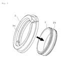
- a sliding bearing according to the present invention is a radial sliding bearing comprising an inner ring and an outer ring, characterized in that one of the inner ring and the outer ring made of a melt-cast metal have a concavely curved surface along part of the axial direction, and the other comprises an article molded from a resin composition having a convexly curved surface along part of the axial direction and the convexly curved surface contacting and sliding against the concavely curved surface, and the inner ring and the outer ring relatively rotate without contacting each other apart from contacting parts of the convexly curved surface and the concavely curved surface.
- the sliding bearing according to the present invention is characterized in that the inner ring and the outer ring are (1) a combination in which the inner ring made of melt-cast metal have the concavely curved surface on the outer circumference and a bearing hole for mating with a support shaft on the inner circumference, and the outer ring comprises an article molded from a resin composition having the convexly curved surface on the inner circumference, or (2) a combination in which the inner ring comprises an article molded from a resin composition, the article having the convexly curved surface on the outer circumference and a bearing hole for mating with a support shaft on the inner circumference, and the outer ring made of melt-cast metal have the concavely curved surface on the inner circumference.
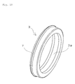
- the sliding bearing according to the present invention is characterized in that the article molded from a resin composition is an annular article having a joint in at least one location.
- the sliding bearing according to the present invention is characterized in that a convex portion constituting the convexly curved surface is not formed within a range of ⁇ 10° with respect to the joint.
- the sliding bearing according to the present invention is characterized in that the surface roughness of the concavely curved surface is no more than 0.3 ⁇ m Ra.
- the sliding bearing according to the present invention is characterized in that the melt-cast metal is high-carbon chromium bearing steel, chromium-molybdenum steel, machine frame carbon steel, or stainless steel.
- the sliding bearing according to the present invention is characterized in that the inner ring made of melt-cast metal is an inner ring for a roller bearing, or the outer ring made of melt-cast metal is an outer ring for a roller bearing.
- the sliding bearing according to the present invention is characterized in that the base resin of the resin composition is at least one synthetic resin selected from thermoplastic PI resin, polyether ketone (PEK) resin, PEEK resin, polyether ketone etherketone ketone (PEKEKK) resin, PPS resin, PAI resin, PA resin, polyethylene (PE) resin, and polyacetal (POM) resin.
- the base resin of the resin composition is at least one synthetic resin selected from thermoplastic PI resin, polyether ketone (PEK) resin, PEEK resin, polyether ketone etherketone ketone (PEKEKK) resin, PPS resin, PAI resin, PA resin, polyethylene (PE) resin, and polyacetal (POM) resin.
- the sliding bearing according to the present invention is characterized in that the resin composition contains polytetrafluoroethylene (PTFE) resin.
- PTFE polytetrafluoroethylene
- the sliding bearing according to the present invention is also characterized in that the resin composition contains at least one selected from carbon fibers, aramid fibers, whiskers, mica, graphite, and talc.
- the sliding bearing according to the present invention is also characterized in that the resin composition contains electroconductive carbon, and the volume resistivity of the article molded from a resin composition is less than 1 ⁇ 10 6 ⁇ cm.
- the sliding bearing according to the present invention is characterized in that when the outer ring comprising an article molded from a resin composition has a joint, the inner diameter of the convex portion constituting the convexly curved surface on the inner circumference of the outer ring is greater than the outer diameter of the concave portion constituting the concavely curved surface on the outer circumference of the inner ring when the joint is in an abutting state.
- the sliding bearing according to the present invention is characterized in that the radius of curvature of the concavely curved surface differs from the radius of curvature of the convexly curved surface.
- the sliding bearing according to the present invention is characterized in that the convexly curved surface has an uncurved surface portion formed along the entire circumference of the axial-direction center of the convexly curved surface.
- the sliding bearing according to the present invention is also characterized in that the article molded from a resin composition is an injection-molded article, and an injection molding parting line is formed on the uncurved surface portion.
- the sliding bearing according to the present invention is characterized in that a lubricant is disposed between sliding surfaces of the inner ring and the outer ring.
- the sliding bearing according to the present invention is also characterized in that a lubricant-retaining groove constituted by an axial-direction indentation is formed in at least one location on a load-bearing portion of the article molded from a resin composition.
- the sliding bearing according to the present invention is characterized in that the lubricant is at least one grease selected from fluorinated grease, urea grease, and lithium grease.
- the sliding bearing according to the present invention is also characterized in that the lubricant is an electroconductive grease.
- the sliding bearing according to the present invention is characterized in that the outer ring or the inner ring comprises at least one non-sliding surface selected from a recessed detent, a raised detent, and a flange.
- the sliding bearing according to the present invention is characterized in that the sliding bearing is used in a fuser unit, transfer unit, developer unit, or paper-conveying roller for feeding or ejecting paper in an image forming apparatus, or in a belt-driving unit for an ink cartridge carriage in an inkjet printer.
- the sliding bearing according to the present invention is characterized in that the melt-cast metal is stainless steel, and the sliding bearing is used in a food product machine.
- the image forming apparatus according to the present invention is characterized in being provided with the sliding bearing according to the present invention and a roller or shaft supported by the sliding bearing.
- the sliding bearing according to the present invention is a radial sliding bearing comprising an inner ring and an outer ring, one of the inner ring and the outer ring made of a melt-cast metal have a concavely curved surface along part of the axial direction, and the other ring comprises an article molded from a resin composition, the article having a convexly curved surface along part of the axial direction that contacts and slides against the concavely curved surface, and the inner ring and the outer ring relatively rotate without contacting each other apart from contacting parts of the convexly curved surface and the concavely curved surface.
- one of the inner ring and the outer ring is made of melt-cast metal, reductions in lubricating power due to wear shedding of metal particulate or base oil being drawn into holes can be prevented.
- the concavely curved surface has better surface precision compared to cases in which the ring is made of sintered metal, and friction torque is more stable.
- there is no limit upon the rotational directions of the inner and outer rings allowing identical sliding bearings to be used at both ends of the roller or shaft.
- the bearing comprises two parts, the inner ring and the outer ring, and thus has fewer parts and a simpler structure than a ball bearing.
- This allows for easy manufacture, enables reductions in manufacturing steps and assembly time, and allows for low-cost provision.
- one of the inner ring or the outer ring being an article molded from a resin composition yields self-insulating properties and the like not found in ball bearings, eliminating the need to provide a separate insulating sleeve or the like.
- it is easy to replace the sliding bearing alone, as in the case of a ball bearing.
- the material and surface roughness of the counterpart roller or shaft do not affect friction torque or wear levels, unlike resin sliding bearings that directly slide against the counterpart roller or shaft.
- the concavely and convexly curved surfaces of the inner ring and the outer ring contact each other, and the inner ring and outer relatively rotate without contacting each other except at these contacting parts, thereby allowing the contact surface area of the frictional surfaces to be reduced and enabling reductions in friction torque over conventional resin sliding bearings.
- the sliding contact surfaces of the inner ring and the outer ring have complementary concavely and convexly curved surfaces, allowing positional deviation of the inner ring and the outer ring in the axial direction to be prevented, and the rings do not contact each other apart from the contacting parts of the convexly curved surface and the concavely curved surface, allowing moment loads to be tolerated.
- the sliding bearing according to the present invention possesses features striking a halfway point between a ball bearing and a conventional resin sliding bearing in terms of both friction torque and manufacturing costs, and is capable of tolerating moment loads.
- one of the inner ring or the outer ring be an annular article (article molded from a resin composition) having a joint in at least one location facilitates assembly with the other ring, which is made of melt-cast metal.
- the convex portion constituting the convexly curved surface is not formed within a range of ⁇ 10° with respect to the joint, promoting stabilized friction torque and improved bearing reliability.
- melt-cast metal be high-carbon chromium bearing steel, chromium-molybdenum steel, machine frame carbon steel, or stainless steel prevents wear damage to the molded article arising from sliding contact with the article molded from a resin composition, and allows stable low torque and low wear to be maintained for extended periods.
- an inner ring or an outer ring for use with a roller bearing (ball bearing) as the inner ring or the outer ring means that the concavely curved surface constituting the sliding surface contacting the article molded from a resin composition is a rolling surface of high precision, leading to stabilization of rolling performance.
- using an inner ring or an outer ring for a general-purpose roller bearing allows the sliding bearing to be manufactured at low cost.
- the base resin of the resin composition forming one of the inner ring or the outer ring be at least one type of synthetic resin selected from thermoplastic PI resin, PEK resin, PEEK resin, PEKEKK resin, PPS resin, PAI resin, PA resin, PE resin, and POM resin allows for ease of handling when assembling the ring with its counterpart, and keeps the ring from breaking even if it expands during assembly.
- PTFE resin as a solid lubricant in the resin composition reduces friction torque and creates stability.
- the application and interposition of a lubricant between the sliding surfaces of the inner ring and the outer ring also contributes to the improvement of low friction torque effects and project stability against the occurrence of localized solid contact or grease dry-out.
- including at least one type of reinforcing material selected from carbon fibers, aramid fibers, whiskers, mica, graphite, and talc in the resin composition further increases wear resistance. Moreover, increasing elasticity makes friction torque and wear resistance less subject to the effects of increases in temperature arising from frictional heat generation or the like, allowing for satisfactory use.
- Including electroconductive carbon in the resin composition and having the volume resistivity be less than 1 ⁇ 10 6 ⁇ cm allows the sliding bearing to be used as an electroconductive bearing.
- the outer ring constituted by the article molded from a resin composition has a joint, having the inner diameter of the convex portion constituting the convexly curved surface on the inner circumference of the outer ring be greater than the outer diameter of the concave portion constituting the concavely curved surface on the outer circumference of the inner ring when the joint is in an abutting state keeps the outer ring from clinging to the inner ring during use, ensuring that operating clearance is secured, and also creating an aligning function. Low torque and low wear are thereby guaranteed, yielding a highly reliable bearing.
- the contact surface area of the inner ring and the outer ring can be reduced, reducing torque.
- Forming an uncurved surface portion along the entire circumference of the axial center of the convexly curved surface creates contact with the concavely curved surface at two locations, allowing for the suppression of backlash between the inner and outer rings and stabilizing friction torque.
- one of the inner ring or the outer ring be an injection-molded article of the resin composition and forming an injection molding parting line on the uncurved surface portion facilitates injection molding and prevents interference with the other sliding contact surface even if burring or flash is present on the parting line.
- Applying and interposing lubricant between the sliding surfaces of the inner ring and the outer ring further reduces friction torque as well as wear levels, and allows performance lifespan to be greatly extended.
- having the lubricant be an electrically conductive grease allows the sliding bearing to be used as an electroconductive bearing.
- a lubricant-retaining groove constituted by an axial-direction indentation on a load-bearing portion of the article molded from a resin composition allows for the stable supply of lubricant to the sliding surfaces.
- Providing at least one non-sliding surface selected from a recessed detent, a raised detent, and a flange on the outer ring or the inner ring allows this part to be used as a part for mounting or aligning on a metal base plate, housing, or the like of an image forming apparatus.
- the sliding bearing according to the present invention promotes reductions in friction torque, allows moment loads to be tolerated, is less expensive to manufacture than a ball bearing, and does not require an insulating sleeve, allowing the bearing to be advantageously used as a bearing for a fuser unit, transfer unit, developer unit, or paper-conveying roller for feeding or ejecting paper in an image forming apparatus or for a belt-driving unit of an ink cartridge carriage in an inkjet printer.
- the image forming apparatus according to the present invention is provided with the sliding bearing according to the present invention and a roller or shaft supported by the sliding bearing, allowing the friction torque of the roller or shaft to be reduced and moment loads to be tolerated.
- the sliding bearing is less expensive to manufacture than a ball bearing and does not require an insulating sleeve, allowing the overall cost of manufacturing the apparatus to be reduced.
- the sliding bearing according to the present invention comprises two parts, the inner ring and the outer ring, and has no rolling elements such as balls, allowing size, weight, and space requirements to be easily reduced.
- the use of stainless steel as the melt-cast metal allows the bearing to be advantageously used as a bearing for supporting a rotary shaft in a food product machine in which the bearing comes into direct or indirect contact with raw food materials or finished (or semi-finished) food products, especially in severe usage conditions, such as in salt solutions or the like.
- the need to use grease can be eliminated, in which case there is no risk of the problem of grease leakage.
- the disposition of a predetermined non-toxic lubricant meeting the USDA H-1 designation or FDA standards, as necessary, between the sliding surfaces of the inner ring and the outer ring allows for further reductions in friction torque as well as wear levels, and allows performance lifespan to be greatly extended.
- the sliding bearing according to the present invention is a radial sliding bearing constituted by two members, the outer ring and the inner ring, and subjected to loads in the radial direction.
- One of the inner ring and the outer ring made of a melt-cast metal have a concavely curved surface along part of the axial direction
- the other ring comprises an article molded from a resin composition having a convexly curved surface along part of the axial direction that contacts and slides against the concavely curved surface, and the inner ring and the outer ring relatively rotate without contacting each other apart from the contacting parts of the convexly curved surface and the concavely curved surface.
- a convexly curved surface and a concavely curved surface that slide relative to one another are provided along parts of the axial directions of the inner ring and the outer ring, thereby providing non-contacting portions at the two ends of the inner ring and the outer ring further outward in the axial direction than the respective axial direction parts. It is preferably that the parts of the axial directions exclude the axial ends in order to ensure that there are non-contacting parts of the convexly curved surface and the concavely curved surface at both outer ends in the axial direction.
- Embodiments of specific combinations of an inner ring and an outer ring include (1) a combination in which the inner ring made of melt-cast metal have the concavely curved surface on the outer circumference and a bearing hole for mating with a support shaft on the inner circumference, and the outer ring comprises an article molded from a resin composition having the convexly curved surface on the inner circumference, or (2) a combination in which the inner ring comprises an article molded from a resin composition having the convexly curved surface on the outer circumference and a bearing hole for mating with a support shaft on the inner circumference, and the outer ring made of melt-cast metal have the concavely curved surface on the inner circumference.
- FIG. 1 is a perspective view of a sliding bearing according to the present invention
- FIG. 2 is a head-on view, axial direction cross-sectional view (along line A-A), and partially magnified view of an axial direction cross-sectional view of the sliding bearing.
- a sliding bearing 1 is provided with an inner ring 2 of melt-cast metal and an outer ring 3 constituted by an article molded from a resin composition.
- the sliding bearing 1 is a radial bearing. As shown in FIG.
- the inner ring 2 comprises a concavely curved surface 2a on the outer circumference and a bearing hole 4 for mating with a support shaft on the inner circumference.
- the outer ring 3 comprises a convexly curved surface 3a that contacts and slides against the concavely curved surface 2a on the outer circumference of the inner ring 2.
- the concavely curved surface 2a is provided along part (the central part) of the axial direction of the inner ring 2, and the convexly curved surface 3a along part (the central part) of the axial direction of the outer ring 3.
- the concavely curved surface 2a on the outer circumference of the inner ring 2 is a concave surface continuously formed in the circumferential direction along the outer circumference of the inner ring 2, and is a concavely curved surface having an arc-shaped (R-shaped) axial cross section.
- the convexly curved surface 3a on the inner circumference of the outer ring 3 is a convex surface continuously or discontinuously formed in the circumferential direction along the inner circumference of the outer ring 3, and is a convexly curved surface having a roughly arc-shaped (R-shaped, with a partial uncurved surface portion as necessary) axial cross section corresponding to the concavely curved surface 2a of the inner ring 2.
- “Arc-shaped” encompasses circular, elliptical, and other desired types of curvilinear shapes.
- the concavely curved surface 2a on the outer circumference of the inner ring 2 and the convexly curved surface 3a on the inner circumference of the outer ring 3 are sliding surfaces.
- the concavely curved surface 2a and the convexly curved surface 3a slidingly contact, and the inner ring 2 and the outer ring 3 relatively rotate. At least parts of these surfaces are in sliding contact.
- the inner ring 2 and the outer ring 3 do not contact each other except at the concavely curved surface 2a and the convexly curved surface 3a.
- the concavely curved surface 2a on the outer circumference of the inner ring 2 and the convexly curved surface 3a on the inner circumference of the outer ring 3 form a slidingly contacting combination, and the two ends outside of the concavely curved surface 2a and the convexly curved surface 3a in the axial direction do not contact, thereby allowing for alignment even if a moment load is generated, enabling such a load to be tolerated.
- the convexly curved surface 3a and the concavely curved surface 2a have complementary shapes, allowing positional deviation of the outer ring 3 and the inner ring 2 in the axial direction to be prevented.
- imparting the concavely curved surface 2a of the inner ring 2 with a curved surface as described above allows an inner ring for an existing ball bearing to be used as the inner ring.
- the radius of curvature of the concavely curved surface 2a on the outer circumference of the inner ring 2 preferably differs from the radius of curvature of the convexly curved surface 3a on the inner circumference of the outer ring 3.
- the radii of curvature of the concavely curved surface and the convexly curved surface are the radii of curvature of the arcs of their respective axial cross sections.
- the radii of curvature of the concavely curved surface and the convexly curved surface (excluding the parts where the convexly curved surface is not present and the parts where the lubricant-retaining groove is present) are constant in the circumferential direction.
- Imparting the concavely curved surface 2a and the convexly curved surface 3a with identical radii of curvature would increase the contact surface area between the inner ring and the outer ring, leading to the risk of increased friction torque.
- a lubricant such as grease is applied to the sliding surfaces, a surface seal is formed, impeding the supply of lubricant to the frictional surfaces.
- the relative sizes of the radii of curvature are preferably such that the radius of curvature of the concavely curved surface 2a is greater than the radius of curvature of the convexly curved surface 3a.
- the inner diameter of the convex portion constituting the convexly curved surface 3a on the inner circumference of the outer ring 3 is preferably greater than the outer diameter of the concave portion constituting the concavely curved surface 2a on the outer circumference of the inner ring 2 when a joint 3b in the outer ring 3 is in an abutting state.
- the inner diameter of the convex portion is the inner diameter of the outer ring at the apical position of the convex portion
- the outer diameter of the concave portion is the outer diameter of the inner ring at the apical position of the concave portion.
- the inner diameter of the outer ring is that of an apical position of an imaginary apical position prior to the provision of the uncurved surface portion. This keeps the outer ring from clinging to the inner ring during use, ensuring that operating clearance is maintained and facilitating alignment. In addition, contact at areas other than load-bearing portions can be avoided, thereby allowing low torque and low wear to be maintained and yielding a highly reliable sliding bearing.
- load-bearing portions refers to those parts where the inner ring and the outer ring of the bearing contact due to pressing loads placed upon the roller or shaft to which the bearing is attached.
- the operating clearance D is the inner diameter A of the convex portion on the inner circumference of the outer ring less the outer diameter B of the concave portion on the outer circumference of the inner ring.
- D A-B.
- Operating clearance at usage temperature is the assumed operating clearance calculated for the inner and outer rings when the whole has reached usage temperature, taking thermal expansion and the like into account.
- FIG. 3 shows a process of assembling the sliding bearing 1.
- the order in which the sliding bearing 1 is assembled is as follows: the outer ring 3 is expanded to at least the maximum outer diameter of the inner ring 2 so that the concavely curved surface 2a on the outer circumference of the inner ring 2 and the convexly curved surface 3a of the outer ring 3 face and contact each other, and fitted onto the concavely curved surface 2a of the inner ring 2 via elastic deformation.
- a lubricant such as grease is applied to the sliding surfaces, it is preferably applied before the outer ring 3 is assembled with the inner ring 2.
- the lubricant is applied at least to the load-bearing portions, preferably along the entire surface of sliding contact between the inner ring and the outer ring.
- FIG. 4 is a perspective view of only the outer ring of the sliding bearing
- FIG. 5 is a head-on view of the outer ring alone and a magnified head-on view of a joint.
- the outer ring 3 is an annular article comprising, on the inner circumference, a convexly curved surface 3a that faces and contacts the concavely curved surface on the outer circumference of the inner ring.
- the "annular article" constituting the outer ring 3 encompasses cases in which there is a separated joint and the ring is not closed at one part, as shown in FIG. 4 , etc.
- any construction such that the outer ring does not come off the inner ring after being combined with the inner ring is acceptable, and any length is acceptable for the circumferential direction length of the annular article as long as it exceeds 180° of the circumference. However, if grease is applied, a length exceeding 340° is preferable in order to avoid grease leakage or contamination of the grease by foreign matter.
- the outer ring 3 is an annular article having a joint 3b. It is acceptable for there to be a joint 3b in at least one location, or joints may be provided at multiple locations. If the outer ring has joints at multiple locations and comprises multiple conjoined articles, the need to expand the outer ring during the process of assembling it with the inner ring is eliminated, which is useful when the outer ring is formed from a synthetic resin lacking toughness. However, increasing the number of parts in the outer ring increases its price and requires multiple articles to be joined together and fixed in place to prevent the outer ring coming off the inner ring after assembly; thus a single article having a joint at one location, as shown in FIG. 4 , etc., is preferable. Having a single joint also facilitates assembly and keeps the outer ring from readily coming off the inner ring after assembly.
- the convex portion constituting the convexly curved surface 3a on the inner circumference of the outer ring 3 not be formed within a range of ⁇ 10° with respect to the joint 3b, as shown in FIG. 5 .
- a range of ⁇ X° with respect to the joint signifies a range, taking the position of the joint (if constituted by two separated ends, a position centrally located between the end faces in the circumferential direction) on the circumference of the annular outer ring as 0°, encompassed by a central angle of ⁇ X° from this position.
- the convex portion of the outer ring 3 is not formed in a range of ⁇ 10° with respect to the joint 3b.
- the joints constitute seams, and may protrude towards the inner diameter side in sliding contact with the inner ring. In such cases, not only the load-bearing portions but also the joints of the outer ring slidingly contact the inner ring, destabilizing friction torque. In the case of an outer ring having only one joint, the joint may sag inward in the direction of the inner diameter, similarly destabilizing friction torque.
- the joint i.e., the convex portion on the inner circumference of the outer ring in the vicinity of the joint
- the maximum extent of the inner ring contacting the outer ring of the sliding bearing is a range of ⁇ 45°, substantially roughly 30°, from the load-bearing portion; thus, it is not necessarily essential to form the convexly curved surface outside the range of ⁇ 45° from the load-bearing portion.
- the two ends of the convex portion constituting the convexly curved surface 3a on the inner circumference of the outer ring 3 preferably form an angle of 90° or less with respect to the tangent line of the inner circumference of the outer ring.
- An angle of 60° or less is more preferable.
- a straight line connecting the two arc-shaped ends in cross section preferably forms the abovementioned angle with respect to the tangent line of the inner circumference of the outer ring.
- the arrangement described above is capable of preventing grease from being scraped off by the ends of the convex portion of the inner circumference, stabilizing the supply of grease to the frictional surfaces.
- the two ends of the convex portions on the inner circumference of the outer ring form angles of 45° with respect to the tangent line of the inner circumference of the outer ring.
- an uncurved surface portion 3c be formed on the convexly curved surface 3a along the entire circumference of the central part of the axial direction of the convexly curved surface 3a of the outer ring 3, as shown in FIG. 4 .
- the uncurved surface portion 3c can be, for instance, a flat-shaped portion having a linear axial cross section.
- an injection molding parting line is preferably formed on the uncurved surface portion 3c. This arrangement facilitates injection molding of the outer ring and prevents interference with the sliding contact surface of the inner ring even if burrs or flash is formed on the parting line, as well as negative effects upon frictional forces.
- a lubricant such as grease or lubricating oil
- the formation of an uncurved surface portion 3c ensures that a hollow part is present between the uncurved surface portion 3c and the concavely curved surface 2a on the outer circumference of the inner ring 2.
- This part constitutes a lubricant-retaining groove, and also serves to retain the lubricant (see FIG. 2 ).
- a lubricant such as grease or lubricating oil
- an "axial-direction indentation” is a concave portion in the convex portion constituting the convexly curved surface on the inner circumference of the outer ring as seen from the apex of the convex portion, and has a shape penetrating the convex portion in the axial direction.
- a lubricant-retaining groove 3d penetrating the convex portion constituting the convexly curved surface 3a on the inner circumference of the outer ring 3 is formed at a joint-facing portion constituting a load-bearing portion. Lubricant can be retained within the lubricant-retaining groove 3d, enabling stable friction reduction. If the load-bearing portion is at a fixed location, a lubricant-retaining groove 3d is preferably disposed at one location on the load-bearing portion, as shown in FIG. 4 .
- the load-bearing portion varies or shifts according to the structure of the apparatus, the location at which the bearing is used, or the method by which the bearing is used, it is also possible to provide a lubricant-retaining groove along the entire circumference of the inner diameter, or at multiple locations corresponding to load-bearing portions.
- the depth of the lubricant-retaining groove 3d from the apex of the convex portion on the inner circumference of the outer ring or the circumferential direction width thereof is not particular limitation upon the depth of the lubricant-retaining groove 3d from the apex of the convex portion on the inner circumference of the outer ring or the circumferential direction width thereof, but a depth of at least 0.5 mm and a circumferential direction width of at least 0.5 mm are preferable in order to obtain grease-retaining effects.
- the circumferential direction width is too great, the possibility of backlash contact with the bottom of the groove arises; thus, the circumferential direction wide is preferably no more than 10% of the inner diameter of the outer ring.
- the inner diameter of the outer ring is the inner diameter of the convex portion constituting the convexly curved surface on the inner circumference of the outer ring.
- a recessed detent 3e and a flange 3f are provided.
- the recessed detent 3e mates with a convex portion (not shown) formed on a housing or the like.
- the outer ring 3 is an article molded from a resin composition.
- a resin composition There is no particular limitation upon the type of synthetic resin constituting the base resin of the resin composition, but it must at least exhibit characteristics and assembly properties (heat resistance, mechanical strength, etc.) suited to the conditions in which the sliding bearing is used.
- An injection-moldable synthetic resin is preferable, as this will facilitate manufacturing and allow costs to be reduced.
- Examples of the base resin (synthetic resin) of the resin composition forming the outer ring are thermoset PI resin, thermoplastic PI resin, PEKEKK resin, PEK resin, PEEK resin, wholly aromatic polyester resin, polytetrafluoroethylene-perfluoroalkyl vinyl ether copolymer (PFA) resin, tetrafluoroethylene-hexafluoropropylene copolymer (FEP) resin, ethylene-tetrafluoroethylene copolymer (ETFE) resin, polyethylene terephthalate resin (PET), polybutylene terephthalate resin (PBT), PPS resin, PAI resin, PA resin, PE resin, POM resin, and phenolic resin. These resins may be used singly in polymer alloys comprising a mixture of two or more types.
- thermoplastic resin that is capable of being injection molded and recycled as the synthetic resin.
- a crystalline resin is especially preferable due to its superior friction and wear properties.
- thermoplastic PI resin PEKEKK resin, PEK resin, PEEK resin, PPS resin, PAI resin, PA resin, PE resin, and POM resin. These resins are tough, and thus will not break even if there is one joint and the ring expands when being assembled with the inner ring. In addition, these resins will not be contaminated even if a lubricant such as grease is applied, eliminating the risk of solvent cracks.
- thermoplastic resins that suits the location and conditions (heat resistance, mechanical strength, etc.) under which the sliding bearing is used and allows for the most inexpensive manufacturing may be selected from these thermoplastic resins.
- heat resistance of 150°C or greater is necessary for a sliding bearing for supporting a heated roller, such as a fuser roller or pressure roller, of a fuser unit in an image forming apparatus.
- thermoplastic PI resin PEKEKK resin, PEK resin, PEEK resin, PPS resin, or PAI resin, which exhibit superior creep resistance, load resistance, wear resistance, and the like.
- thermoplastic PI resin having a continuous usage temperature of 240°C or PEKEKK resin, PEK resin, or PEEK resin having a continuous usage temperature of 250°C or greater is preferable.
- PA resin for a sliding bearing used to support a shaft of a transfer belt guide or the like in an transfer unit, a shaft of a cartridge or the like in a developer unit, a paper-conveying roller or shaft for feeding or ejecting paper, or a shaft of a belt-driving unit for an ink cartridge carriage in an inkjet printer
- inexpensive PA resin, PE resin, or POM resin may be selected, as the bearing is used at room temperature. More preferable is POM resin, which exhibits little molding contraction or change in water absorption dimensions and high dimensional precision and stability, or low water-absorbent modified PA resin.
- thermoplastic PI resin that can be used in the present invention is AURUM®; Mitsui Chemicals,Inc., which has a melting point of around 388°C and a glass transition point of 250°C.
- AURUM® a commercially available thermoplastic PI resin that can be used in the present invention
- a crystallizing treatment thermal treatment
- this crystallizing treatment is not essential if it is not problematic in terms of bearing usage conditions (heat resistance, grease resistance, etc.) if the resin in non-crystalline.
- a crystallizing treatment is essential if temperature conditions exceed the mold temperature (about 200°C).
- a PEEK resin is a crystalline thermoplastic resin having the polymer structure shown in formula (1) below, in which a benzene ring is linked to a carbonyl group by an ether bond at a para site.
- a PEEK resin having the structure shown in formula (1) has a melting point of about 343°C, a glass transition point of 143°C, and superior heat resistance, creep resistance, load resistance, wear resistance, and sliding properties, as well as superior moldability.
- PEEK resins examples include PEEK resins (90P, 150P, 380P, 450P, etc.) produced by Victrex plc., KetaSpire® (KT-820P, KT-880P, etc.) produced by Solvay Advanced Polymers K.K., and VESTAKEEP® (1000G, 2000G, 3000G, 4000G, etc.) produced by Daicel-Degussa Ltd.
- PEKEKK resin and PEK resin are more heat resistant resins that PEEK resin.
- the melting point of PEKEKK resin is about 387°C, and the glass transition point is 162°C.
- the melting point of PEK resin is about 373°C, and the glass transition point is 152°C.
- An example of a commercially available PEKEKK resin usable in the present invention is ST-G45, produced by Victrex plc, and an example of a commercially available PEK resin is HT-G22, produced by Victrex plc.
- a PPS resin is a crystalline thermoplastic resin having the polymer structure shown in formula (2) below, in which a benzene ring is linked by a sulfur bond at a para site.
- a PPS resin having the structure shown in formula (2) has a melting point of about 280°C, a glass transition point of 90°C, and extremely high rigidity and superior heat resistance, dimensional stability, wear resistance, and sliding properties.
- PPS resins according to their molecular structure such as crosslinked, semi-crosslinked, straight-chain, and branch-chained; in the present invention, these can be used without any limitation upon molecular structure or molecular weight.
- a semi-crosslinked resin having a comparatively high level of toughness or a branch-chained resin having the highest level of toughness examples include #160 produced by Tosoh Corporation and T4AG or LR2G produced by DIC.
- PA resins examples include PA6 resins (AMILAN® produced by Toray, Ultramid B produced by BASF, etc.), PA66 resins (AMILAN® produced by Toray Industries,Inc, Ultramid A produced by BASF, etc.), PA46 resins (Stanyl produced by DSM), PA12 resins (DAIAMID® produced by Daicel-Degussa Ltd, etc.), PA610 resins
- PA612 resins Zytel® PA612 produced by DuPont, Polyamide 612 produced by Daicel-Degussa Ltd, etc.
- modified PA6T resins ARLENTM produced by Mitsui Chemicals,Inc., Ultramid T produced by BASF, etc.
- modified PA9T resins GenestarTM produced by Kuraray Co.,Ltd.
- PA resins may be used singly in polymer alloys comprising a mixture of two or more types. Because PA resin has a high rate of water absorption and easily undergoes changes in dimensions, modified PA6T resin or modified PA9T resin, which, of the abovementioned resins, have the lowest water absorption rates, is preferable.
- PE resins of a wide variety of molecular weights from low molecular weight to ultra-high molecular weight, are commercially available.
- ultra-high molecular weight PE cannot be injection molded.
- the higher the molecular weight of the PE resin the high its physical properties and wear resistance; thus, high-molecular-weight PE capable of being injection molded is preferable.
- Examples of commercial PE resins that can be used in the present invention are LUBMERTM L5000 and L4000, produced by Mitsui Chemicals,Inc.
- POM resins Three types of POM resins that can be used in the present invention are homopolymers (TenacTM produced by Asahi Kasei Corporation, Durulene produced by DuPont), copolymers (TenacTM C produced by Asahi Kasei Corporation, DURACON® produced by Polyplastics Co.,Ltd. etc.), and block copolymers (TenacTM produced by Asahi Kasei Corporation), but the present invention is not particular limited to these.
- homopolymers TenacTM produced by Asahi Kasei Corporation, Durulene produced by DuPont
- copolymers TenacTM C produced by Asahi Kasei Corporation, DURACON® produced by Polyplastics Co.,Ltd. etc.
- block copolymers TenacTM produced by Asahi Kasei Corporation
- PEKEKK resin, PEK resin, PEEK resin, PPS resin, PAI resin, PA resin, PE resin, and POM resin crystallize within the mold during injection molding.
- thermal treatment there is no need to perform a crystallizing treatment (thermal treatment).
- the temperature at which the bearing is used is equal to or higher than the injection molding mold temperature, the bearing will undergo dimensional changes due to mitigation of molding stress, thus necessitating an annealing treatment (thermal treatment) at a temperature equal to or higher than the temperature at which the bearing is used.
- a solid lubricant in the resin composition forming the outer ring.
- PTFE resin is especially preferably included as a solid lubricant.
- the proportion of solid lubricant in the composition is preferably 3-40 volume% of the total amount of resin composition, more preferably from 10-30 volume%. If the lubricant content is less than 3 volume%, friction reduction will be insufficient, and, if it exceeds 40 volume%, there is a risk of reductions in wear resistance.
- the PTFE resin used in the present invention may be any of a molding powder obtained via suspension polymerization, a fine powder obtained via emulsion polymerization, or recycled PTFE.
- recycled PTFE that resists forming fibers due to shearing during molding and increases in melt viscosity.
- the recycled PTFE is a thermally treated (i.e., having a thermal history of firing or the like) powder or a powder that has been irradiated with gamma radiation or an electron beam. Because the recycled PTFE has been thermally treated once before, it is not subject to transformations such as fiber formation due to friction shearing. Thus, friction torque is stable, and wear resistance is improved.
- Examples include thermally treated molding powders or fine powders, similar powders that have been further irradiated with gamma radiation or an electron beam, powders formed by pulverizing a molding powder or fine powder compact, similar powders that have been subsequently irradiated with gamma radiation or an electron beam, and gamma radiation- or electron beam-irradiated molding powders or fine powders.
- Examples of commercially available PTFE resins capable of being used in the present invention include: KTL-610, KTL-350, KTL-8N, and KTL-400H, all produced by Kitamura Limited; Teflon® 7-J, produced by Mitsui DuPont Fluorochemicals Co.,Ltd.; Fluon® G163, L169J, L170J, and L173J, all produced by Asahi Glass Co.,Ltd.; PolyflonTM M-15 and LubronTM L-5 produced by Daikin Industries,Ltd; and HostaflonTM TF 9205 and TF 9207 produced by Hoechst AG. Also acceptable is PTFE modified by a perfluoroalkyl ether group, a fluoroalkyl group, or a sidechain group comprising another fluoroalkyl.
- a fibrous, flaked, or sheet-shaped reinforcing material is preferably included in the resin composition forming the outer ring. This is especially useful in the case of a heated roller bearing used at high temperatures of 150°C or higher as it promotes increased strength and elasticity at high temperatures.
- reinforcing materials include glass fibers, carbon fibers, aramid fibers, whiskers, slag wool, mica, talc, graphite, glass flakes, molybdenum disulfide, tungsten disulfide, and boron nitride.
- the proportion of reinforcing material in the composition is preferably 1-20 volume% of the total amount of resin composition, more preferably from 5-10 volume%. If the reinforcing material content is less than 1 volume%, there will be insufficient improvement in wear resistance, and if it exceeds 20 volume%, friction properties will be inhibited, leading to the risk of wear damage to the inner ring constituting the counterpart sliding member. In addition, rigidity will be high, potentially leading to breakage when the outer ring is expanded and fitted onto the inner ring.
- At least one selected from carbon fibers, aramid fibers, whiskers, mica, talc, and graphite is preferably included.
- Using these materials allows for wear to the inner ring constituting the counterpart sliding member to be suppressed while maintaining reinforcing effects.
- the wear resistance and high-temperature strength and elastic modulus retention of the outer ring constituted by a resin molded article can also be further improved.
- lubricative flaked graphite is ideal as a reinforcing material capable of suppressing wear to the inner ring constituting the counterpart sliding member while maintaining reinforcing effects.
- the surface of the reinforcing material may be treated using an agent containing epoxy resin, polyamide resin, polycarbonate resin, polyacetal resin, or the like, or a silane coupling agent (silane treatment).
- the carbon fibers used in the present invention may be either pitch-based or PAN-based as classified according to their raw material, but PAN-based carbon fibers having a high elastic modulus are preferable.
- PAN-based carbon fibers having a high elastic modulus There is no particular limitation upon the firing temperature, but a carbide product fired at a temperature of roughly 1000-1500°C is preferable to a graphitized product fired at a high temperature of 2000°C or higher, as the inner ring in sliding contact will be less subject to wear damage.
- the carbon fibers have an average fiber diameter of 20 ⁇ m or less, preferably 5-15 ⁇ m or less. Carbon fibers thicker than the abovementioned range are not preferable as they will generate extreme pressure, increasing wear damage to the inner ring.
- pitch-based carbon fibers examples include Kureka Milled (M101S, M101F, M101T, M107S, M1007S, M201S, and M207S) produced by Kureha Corporation, and Donacarbo Milled (S241, S244, SG241, and SG244) produced by Osaka Gas Chemicals Co.,Ltd.
- PAN-based fibers examples include Tenax® HTA-CMF0160-0H and CMF0040-0H produced by Toho Tenax Co.,Ltd.
- the aramid fibers used in the present invention may be either para- or meta-aramid fibers as classified according to their molecular structure. Because aramid fibers are organic, they are soft and will not readily cause wear damage to the inner ring in sliding contact. Examples of commercially available para-aramid fibers include Twaron and Technora produced by Teijin Limited. and Kevlar produced by DuPont, and an example of commercially available meta-aramid fibers is Conex produced by Teijin Limited.
- whiskers used in the present invention include potassium titanate whiskers (Otsuka Chemicals Co., Ltd.), titanium oxide whiskers (Ishihara Sangyo KAISHA, Ltd.), zinc oxide whiskers (Panasonic Corporation), aluminum borate whiskers (Shikoku Chemicals Corporation), calcium carbonate whiskers (Maruo Calcium Co.,Ltd.), and wollastonite.
- potassium titanate whiskers Otsuka Chemicals Co., Ltd.
- titanium oxide whiskers Ishihara Sangyo KAISHA, Ltd.
- zinc oxide whiskers Panasonic Corporation
- aluminum borate whiskers Shikoku Chemicals Corporation
- calcium carbonate whiskers Maruo Calcium Co.,Ltd.
- wollastonite There is no particular restriction upon Mohs hardness, but a low hardness is preferable; for example, potassium titanate whiskers (Otsuka Chemicals Co.,Ltd.), calcium carbonate whiskers (Maruo Calcium Co.,Ltd.), or wollastonite having
- At least one selected from mica, graphite, and talc may be added in addition to carbon fibers, aramid fibers, or whiskers. Using these materials imparts wear resistance due to the reinforcing effects and allows wear to the inner ring constituting the counterpart sliding member to be suppressed without inhibiting friction performance.
- Graphite is especially preferable as it is also effective as a solid lubricant.
- the sliding bearing must be electroconductive, as in cases in which a fuser roller is grounded via the sliding bearing, it is preferable to include electroconductive carbon in the resin composition forming the outer ring in order to impart the outer ring, which is a resin part, with electroconductive properties.
- the amount thereof included is preferably adjusted so that the volume resistivity of the outer ring is less than 1 ⁇ 10 6 ⁇ cm.
- Types of electroconductive carbon include carbon nanotubes, fullerenes, carbon powder, and spherical graphite, any of which can be used. Of these, carbon powder is preferable as it does not exhibit shape anisotropy and yields superior cost performance.
- One type of carbon powder is carbon black. Carbon black produced using either a degradation method, such as thermal black oringtylene black, or an incomplete combustion method, such as channel black, gas furnace black, oil furnace black, pine soot, or lamp black, can be used. From considerations of electroconductivity, furnace black, acetylene black, or Ketjenblack® is preferably used, with Ketjenblack being more preferable due to its superior electroconductivity.
- the Ketjenblack preferably has a primary particle diameter of 30-38 nm. This primary particle diameter range allows a sufficient volume resistivity value to be obtained with only a small amount of Ketjenblack.
- the BET specific surface area of the Ketjenblack is preferably 1000-1500 m 2 /g. This specific surface area extent allows for superior volume resistivity stability with only a small amount of Ketjenblack.
- An example of such Ketjenblack is Ketjenblack EC-600 JD produced by Lion Corporation (primary particle diameter: 34 nm; BET specific surface area: 1270m 2 /g).
- a known resin additive may also be added to the resin composition to the extent that the effects of the present invention are not inhibited.
- a friction property improver such as boron nitride, molybdenum disulfide, or tungsten disulfide, a colorant such as powdered carbon, iron oxide, or titanium oxide, or a thermal conductivity improver such as graphite or powdered metallic oxide can be added.
- the feedstock powders can be dry-mixed in a Henschel mixer, ball mixer, ribbon blender, Lödige mixer, or ultra-Henschel mixer, then melt-blended in a melt extruder such as a twin-screw extruder to obtain pellets (granules) for molding.
- a filler may be introduced using a side feed when performing melt-blending in a twin-screw extruder.
- the molding method is preferably injection molding from considerations of manufacturing efficiency.
- the molded product may optionally be annealed or otherwise treated.
- FIG. 6 is a perspective view of only the outer ring of a sliding bearing.
- the concavely curved surface 2a on the outer circumference of the inner ring 2 has an arc-shaped (R-shaped) axial cross section.
- the concavely curved surface 2a constitutes a sliding surface with the outer ring. This shape allows for mitigation of moment loads placed thereupon, and enables reduced torque and wear thanks to stable bearing of pressure.
- An inner ring for use in an existing roller bearing, such as a ball bearing, can be repurposed for use as the inner ring 2.
- the concavely curved surface 2a on the outer circumference constituting the sliding surface with the outer ring is an inner ring rolling surface of a roller bearing and exhibits high precision, leading to stabilized rotation performance.
- the inner ring 2 is made of melt-cast metal, reductions in lubricating power due to wear shedding of metal particulate or base oil being drawn into holes, as in the case of sintered metal, can be prevented.
- the material used for the inner ring 2 so long as it is a melt-cast metal. Examples include high-carbon chromium bearing steel, chromium-molybdenum steel, machine frame carbon steel, stainless steel, cast iron, aluminum alloy, and brass. As high a level of degree of hardness as possible is preferable, as this will decrease wear damage caused by sliding contact with the outer ring.
- high-hardness melt-cast metals examples include high-carbon chromium bearing steel, chromium-molybdenum steel, and machine frame carbon steel. If the bearing is to be used in environments requiring corrosion resistance, such as in high-humidity atmospheres or in a liquid, stainless steel (martensitic or austenitic) is preferable. In order to reduce wear damage due to sliding contact, the metal is preferably subjected to a treatment such as tempering in order to increase surface hardness. If it is not problematic in terms of functioning, a surface treatment such as nickel plating or chromium plating can be performed in order to prevent rust.
- a treatment such as nickel plating or chromium plating can be performed in order to prevent rust.
- a material used for an inner ring of an ordinary roller bearing (such as high-carbon chromium bearing steel) is especially preferably, as it can be inexpensively obtained.
- ordinary roller bearings are tempered, this is not necessary if it is not problematic in terms of functioning.
- the surface roughness of the concavely curved surface (sliding contact surface) on the outer circumference of the inner ring 2 is preferably no more than 0.3 ⁇ m Ra. This is because, as surface roughness decreases, the level of wear caused by microscopic ridges formed during machining digging into the resin outer ring decreases, extending lifespan. In addition, as surface roughness decreases, torque decreases. Methods of machining surface roughness include turning, grinding, and super-finishing, but the present invention is not particularly limited to these. A surface roughness of no more than 0.1 ⁇ m Ra is more preferable.
- the inner ring of an ordinary roller bearing is super-finished to a surface roughness of no more than 0.03 ⁇ m Ra, allowing for further reductions in wear and torque.
- a lubricant such as lubricating oil or grease is preferably applied to the sliding surfaces of the inner ring and the outer ring (i.e., the surfaces of the inner ring and the outer ring that slide). Applying and interposing lubricant between the sliding surfaces allows friction torque as well as wear levels to be further reduced, and performance lifespan to be greatly extended.
- the lubricant there is no particular limitation upon the lubricant as long as it is capable of reducing torque; ordinarily, a grease, lubricating oil, or the like used in sliding bearings can be used.
- base oils if a grease is used include mineral oils such as paraffin-based mineral oil and naphthenic mineral oil; hydrocarbon-based synthetic oils such as polybutene oil, poly-alpha-olefin oil, alkylbenzene oil, alkylnaphthalene oil, and cycloaliphatic compounds; natural oil; and non-hydrocarbon-based synthetic oils such as polyolester oil, phosphate ester oil, diester oil, polyglycol oil, silicone oil, polyphenyl ether oil, alkyldiphenyl ether oil, and fluorinated oil. These base oils may be used singly or in combinations or two or more.
- thickeners used as grease constituents include thickeners based on metal soaps such as aluminum soap, lithium soap, sodium soap, complex lithium soap, complex calcium soap, and complex aluminum soap; urea-based compounds such as diurea compounds or polyurea compounds; and powdered fluororesins such as PTFE resin. These thickeners may be used singly or in combinations or two or more. Known additives may optionally be included in the various greases described above as necessary.
- Fluorinated greases, urea greases, and lithium greases generally used in roller bearings are preferable, as they exhibit superior lubrication and have commercial track records.
- fluorinated greases that can be used in the present invention include Barrierta and Noxlub produced by NOK Klüber, and DemnumTM produced by Daikin Industries,Ltd.
- urea greases include Excelite produced by Kyodo Yushi Co.,Ltd. and Amblygon and Petamo produced by NOK Klüber.
- Examples of commercially available lithium greases include Alvania S grease produced by Showa Shell Sekiyu K.K. and Multemp SRL produced by Kyodo Yushi Co.,Ltd.
- There is no particular limitation upon the viscosity of the base oil or the thickness of the grease and these may be selected according to the conditions in which the sliding bearing is used.
- a grease that suits the location and conditions (heat resistance, mechanical strength, etc.) under which the sliding bearing is used and allows for the most inexpensive manufacturing may be selected from these greases.
- heat resistance of 150°C or greater is necessary for a sliding bearing for supporting a heated roller, such as a fuser roller or pressure roller, of a fuser unit in an image forming apparatus.
- the use of a highly heat-resistant fluorinated grease or urea grease is preferable.
- a sliding bearing used to support a shaft for a transfer belt guide in a transfer unit, a shaft for a cartridge in a developer unit, a paper-conveying roller or shaft for feeding or ejecting paper, or a shaft of a belt-driving unit for an ink cartridge carriage in an inkjet printer is used in temperatures of 100°C or less; thus, an all-purpose, inexpensive lithium grease may be selected.
- electroconductivity is imparted to the outer ring constituting the resin part and to the lubricant present between the inner and outer rings.
- the additive used to impart the grease with electroconductivity examples include graphite and electroconductive carbon.
- graphite has a comparatively large average particle diameter of a few microns to a few dozen microns, it may enter into the sliding surfaces along with the grease, creating an abrasively wearing state, and negatively affected sliding properties.
- the abovementioned electroconductive carbon which comprises microparticles, is preferable as it exhibits little effect upon sliding properties.
- electroconductive fluorinated greases include Barrierta BFX3 (electroconductive carbon formulation) produced by NOK Klüber and Hi-Lube FG-1222 and 1223 produced by Harves Co.,Ltd.
- lubricating oils are oils of the same type as the abovementioned grease base oils. Because a lubricating oil may escape from between the inner ring and the outer ring, a grease, which is not readily extruded outside the bearing, is preferable.
- the grease base oil or lubricating oil preferably has a dynamic viscosity at usage temperature of 3-100 mm 2 /s.
- a dynamic viscosity of less than 3 mm 2 /s makes it difficult to form a lubricant film, increasing friction torque.
- a dynamic viscosity of 100 mm 2 /s will lead to increased friction torque due to viscous resistance.
- a dynamic viscosity of 3-50 mm 2 /s is more preferable.
- Lubrication state is related to operating clearance and the dynamic viscosity of the grease base oil or lubricating oil.
- (mm 2 /s)] at usage temperature is preferably 0.01-2. If the product is less than 0.01, the contact surface area of the inner and outer rings will increase and lubricant film formation will be poor, increasing friction torque. If the product exceeds 2, friction torque will be increased due to the viscous resistance of the oil. A product of 0.02-1 is more preferable.
- the image forming apparatus according to the present invention is provided with the sliding bearing according to the present invention and a roller or shaft supported by the sliding bearing, allowing the friction torque of the roller or shaft to be reduced and moment loads to be tolerated.
- the sliding bearing according to the present invention is less expensive to manufacture than a ball bearing and does not require an insulating sleeve, allowing the overall cost of manufacturing the apparatus to be reduced.
- FIG. 7 is a magnified cross-sectional view of a fuser roller-supporting part in an image forming apparatus.
- a fuser roller 5 of the image forming apparatus is formed from hollow aluminum, and is heated to roughly 200°C by a heater provided in the hollow part.
- a shaft part 5a of the fuser roller 5 is mated to and supported by a bearing hole 4 in an inner ring 2 of a sliding bearing 1.
- the sliding bearing 1 directly supports the shaft part of the fuser roller without the mediation of an insulating sleeve.
- the sliding bearing 1 is engaged and aligned with a housing 6 of the image forming apparatus by a flange 3f provided on the outer circumference of the outer ring 3.
- the fuser roller 5 bends (curves/flexes) due to high temperatures or loads, and, even if a moment load is generated, aligns at the sliding bearing 1, allowing it to tolerate the load.
- the sliding bearing 1 can be configured as an electroconductive bearing as described above. Configuring the sliding bearing 1 as an electroconductive bearing grounds the shaft part 5a via the sliding bearing 1 and the housing 6, allowing for an arrangement in which electricity accumulating on the fuser roller 5 is allowed to escape. If it is necessary that the bearing be non-electroconductive, this can be addressed by making the outer ring non-electroconductive without having to use a separate insulating part such as an insulating sleeve.
- FIGS. 8 and 9 Another embodiment of the sliding bearing according to the present invention (in which the outer ring is made of melt-cast metal) is shown in FIGS. 8 and 9 .
- FIGS. 1-7 feature a sliding bearing comprising a combination of an inner ring made of melt-cast metal and an outer ring constituted by an article molded from a resin composition
- FIGS. 8 and 9 feature a sliding bearing comprising a combination of an outer ring made of melt-cast metal and an inner ring constituted by an article molded from a resin composition.
- FIG. 8 is a perspective view of a sliding bearing according to the present invention
- FIG. 8 is a perspective view of a sliding bearing according to the present invention.
- a sliding bearing 1' is provided with an outer ring 3 of melt-cast metal and an inner ring 2 constituted by an article molded from a resin composition.
- the sliding bearing 1' is a radial bearing.
- the inner ring 2 comprises a convexly curved surface 2b on the outer circumference and a bearing hole 4 for mating with a support shaft on the inner circumference.
- the outer ring 3 comprises a concavely curved surface 3g that contacts and slides against the convexly curved surface 2b on the outer circumference of the inner ring 2.
- the concavely curved surface 3g is provided along part (the central part) of the axial direction of the outer ring 3, and the convexly curved surface 2b along part (the central part) of the axial direction of the outer ring 3.
- the concavely curved surface 3g on the inner circumference of the outer ring 3 is a concave surface continuously formed in the circumferential direction along the inner circumference of the outer ring 3, and is a concavely curved surface having an arc-shaped (R-shaped) axial cross section.
- the convexly curved surface 2b on the outer circumference of the inner ring 2 is a convex surface continuously or discontinuously formed along the circumferential direction on the outer circumference of the inner ring 2, and is a convexly curved surface having a roughly arc-shaped (R-shaped, with a partial uncurved surface portion as necessary) axial cross section corresponding to the concavely curved surface 3g of the outer ring 3.
- the constituent members and concave and convex parts are reversed from the sliding bearing shown in FIGS. 1-7 , but the bearing is similarly capable of tolerating moment loads and preventing axial direction positional shifting of the outer ring and the inner ring.
- the radius of curvature of the convexly curved surface 2b on the outer circumference of the inner ring 2 preferably differs from the radius of curvature of the concavely curved surface 3g on the inner circumference of the outer ring 3.
- the order in which the sliding bearing according to the present embodiment is assembled is as follows: the inner ring 2 is compressed to equal to or less than the minimum inner diameter of the outer ring 3 so that the concavely curved surface 3g on the inner circumference of the outer ring 3 and the convexly curved surface 2b of the inner ring 2 face and contact one another, and is fitted into the concavely curved surface 3g of the outer ring 3 via elastic deformation. Accordingly, a joint is open in the inner ring 2 following assembly. Thus, even if initial clearance should be lost, clinging can be prevented by the closing of the joint.
- the operating clearance D' is the inner diameter A' of the concave portion on the inner circumference of the outer ring less the outer diameter B' of the convex portion on the outer circumference of the inner ring.
- D' A'-B'.
- FIG. 10 is a perspective view of only the outer ring of the sliding bearing according to the present embodiment.
- the concavely curved surface 3g on the inner circumference of the outer ring 3 has an arc-shaped (R-shaped) axial cross section.
- the concavely curved surface 3g constitutes a sliding surface with the inner ring. This shape allows for mitigation of moment loads placed thereupon, and enables reduced torque and wear thanks to stable bearing of pressure.
- An outer ring for use in an existing roller bearing, such as a ball bearing, can be repurposed for use as the outer ring 3.
- the concavely curved surface 3g on the inner circumference constituting the sliding surface with the inner ring is an outer ring rolling surface of a roller bearing and exhibits high precision, leading to stabilized rotation performance.
- the same metal as used to form the inner ring of the embodiment shown in FIGS. 1-7 can be used as the melt-cast metal forming the outer ring 3 of the present embodiment, and similar effects are yielded thereby.
- the surface roughness of the concavely curved surface 3g is also preferably no more than 0.3 ⁇ m Ra, as in the case of the inner ring of the embodiment shown in FIGS. 1-7 .
- FIG. 11 is a perspective view of only an inner ring of the sliding bearing according to the present embodiment
- FIG. 12 is a head-on view of only the inner ring.
- the inner ring 2 is an annular article comprising, on the outer circumference, a convexly curved surface 2b that faces and contacts the concavely curved surface on the inner circumference of the outer ring.
- the "annular article" constituting the inner ring encompasses cases in which there is a separated joint and the ring is not closed at one part, as shown in FIG. 11 , etc.
- any construction such that the inner ring 2 does not come off the outer ring after being combined with the outer ring is acceptable, and any length is acceptable for the circumferential direction length of the annular article as long as it exceeds 180° of the circumference. However, if grease is applied, a length exceeding 340° is preferable in order to avoid grease leakage or contamination of the grease by foreign matter.
- the same composition as used to form the outer ring of the embodiment shown in FIGS. 1-7 can be used as the resin composition forming the inner ring 2 of the present embodiment, and similar effects are yielded thereby.
- the inner ring 2 is an annular article having a joint 2d. It is acceptable for there to be a joint 2d in at least one location, or joints may be provided at multiple locations. If the inner ring has joints at multiple locations and comprises multiple conjoined articles, the need to contract the inner ring during the process of assembling it with the outer ring is eliminated, which is useful when the inner ring is formed from a synthetic resin lacking toughness. However, increasing the number of parts in the inner ring increases its price and requires multiple articles to be joined together and fixed in place to prevent the inner ring coming off the outer ring after assembly; thus a single article having a joint at one location is preferable. Having a single joint also facilitates assembly and keeps the inner ring from readily coming off the outer ring after assembly.
- the convex portion constituting the convexly curved surface 2b on the outer circumference of the inner ring 2 not be formed within a range of ⁇ 10° with respect to the joint 2d, as shown in FIG. 12 .
- a range of ⁇ X° with respect to the joint signifies a range, taking the position of the joint (if constituted by two separated ends, a position centrally located between the end faces in the circumferential direction) on the circumference of the annular inner ring as 0°, encompassed by a central angle of ⁇ X° from this position.
- the convex portion of the inner ring 2 is not formed in a range of ⁇ 10° with respect to the joint 2d.
- the joints constitute seams, and may protrude towards the outer diameter side in sliding contact with the outer ring. In such cases, not only the load-bearing portions but also the joints of the inner ring slidingly contact the outer ring, destabilizing friction torque. In the case of an inner ring having only one joint, the joint may bulge outward in the direction of the outer diameter, similarly destabilizing friction torque.
- the two ends of the convex portion constituting the convexly curved surface 2b on the outer circumference of the inner ring 2 preferably form an angle of 90° or less with respect to the tangent line of the inner circumference of the outer ring.
- An angle of 60° or less is more preferable.
- a straight line connecting the two arc-shaped ends in cross section preferably forms the abovementioned angle with respect to the tangent line of the outer circumference of the inner ring.
- the arrangement described above is capable of preventing grease from being scraped off by the ends of the convex portion of the outer circumference, stabilizing the supply of grease to the frictional surfaces.
- the two ends of the convex portions on the inner circumference of the inner ring form angles of 45° with respect to the tangent line of the inner circumference of the inner ring.
- an uncurved surface portion 2c be formed on the convexly curved surface 2b of the inner ring 2 along the entire circumference of the central part of the axial direction of the convexly curved surface 2b, as shown in FIG. 9 .
- the uncurved surface portion 2c can be, for instance, a flat-shaped portion having a linear axial cross section.
- the concavely curved surface 3g of the outer ring 3 it is possible for the concavely curved surface 3g of the outer ring 3 to contact not just one, but two locations on the apex of the convexly curved surface 2b of the inner ring 2 as seen in axial cross section, allowing axial backlash between the inner and outer rings to be suppressed. Friction torque is also stabilized. In addition, the maximum outer diameter is reduced, yielding superior ease of assembly with the outer ring.
- an injection molding parting line is preferably formed on the uncurved surface portion 2c. This arrangement facilitates injection molding of the inner ring and prevents interference with the sliding contact surface of the inner ring even if burring or flash forms on the parting line, as well as negative effects upon frictional forces.
- a lubricant such as grease or lubricating oil
- the formation of an uncurved surface portion 2c ensures that a hollow part is present between the uncurved surface portion 2c and the concavely curved surface 3g on the inner circumference of the outer ring 3.
- This part constitutes a lubricant-retaining groove, and also serves to retain the lubricant (see FIG. 9 ).
- the same grease or lubricating oil as in the embodiment shown in FIGS. 1-7 can be used.
- a lubricant such as grease or lubricating oil is disposed between the inner and outer rings, it is preferable to form at least one lubricant-retaining groove 2f constituted by an axial-direction indentation on the load-bearing portion of the outer circumference of the inner ring 2. If the load-bearing portion is at a fixed location, a lubricant-retaining groove is preferably disposed at one location on the load-bearing portion, as shown in FIG. 9 .
- the load-bearing portion varies or shifts according to the structure of the apparatus, the location at which the bearing is used, or the method by which the bearing is used, it is also possible to provide a lubricant-retaining groove along the entire circumference of the outer diameter, or at multiple locations corresponding to load-bearing portions.
- the depth of the lubricant-retaining groove from the apex of the convex portion on the outer circumference of the inner ring or the circumferential direction width thereof is not particular limitation upon the depth of the lubricant-retaining groove from the apex of the convex portion on the outer circumference of the inner ring or the circumferential direction width thereof, but a depth of at least 0.5 mm and a circumferential direction width of at least 0.5 mm are preferable in order to obtain grease-retaining effects.
- the circumferential direction width is too great, the possibility of backlash contact with the bottom of the groove arises; thus, the circumferential direction wide is preferably no more than 10% of the outer diameter of the inner ring.
- a raised detent 2e is provided on the inner ring 2 and a metal check ring 7 on the outer ring 3.
- the raised detent 2e mates with a concave portion (not shown) formed in a shaft or the like.
- the sliding bearing combining an inner ring made of melt-cast metal and an outer ring constituted by an article molded from a resin composition is suited for applications in which the inner ring rotates during shaft rotation, and the sliding bearing combining an outer ring made of melt-cast metal and an inner ring constituted by an article molded from a resin composition is suited for applications involving outer ring rotation when the housing around the outer circumference rotates, respectively.
- the convexly curved surface on the inner circumference of the outer ring is not formed in parts, the edge of the convexly curved surface will contact the inner ring when the outer ring rotates.
- the convexly curved surface be formed along the entirety of the inner circumference of the outer ring when the bearing is used in an arrangement in which the outer ring rotates.
- the convexly curved surface on the outer circumference of the inner ring is not formed in parts, it is preferable that the convexly curved surface be formed along the entirety of the outer circumference of the inner ring when the bearing is used in an arrangement in which the inner ring rotates.
- FIG. 13 is a cross-sectional view of an example of a food product processing machine using the sliding bearing according to the present invention
- FIG. 14 is a magnified view of the vicinity of the bearing shown in FIG. 13 .
- sliding bearings 11 according to the present invention are sliding bearings for supporting blending rotary shafts 15 laid laterally over a casing 14a of a food product processing machine 14 for kneading food products.
- the food product processing machine 14 conveys raw food materials introduced via an inlet 14b into the casing 14a to the right while blending it using screw blades 16 provided on rotary shafts 15 rotatably driven by a motor (not shown), and the blended food product is ejected via an outlet 14c.
- the sliding bearings 11 are contained within bearing cases 14d provided on both the left and right end of the casing 14a, and support the two ends of the rotary shafts 15.
- the sliding bearings 11 are radial sliding bearings constituted by two members, an inner ring 12 and an outer ring 13, and are subjected to loads in the radial direction.
- the outer ring 13 is mounted to the bearing cases 14d by a retaining ring 17, and the inner ring 12 is attached to the rotatably driven rotary shaft 15.
- One of the inner ring 12 or the outer ring 13 comprises stainless steel having a concavely curved surface along part of the axial direction
- the other comprises an article molded from a resin composition having a convexly curved surface along part of the axial direction that contacts and slides against the concavely curved surface, and the inner ring 12 and the outer ring 13 relatively rotate without contacting each other apart from the contacting parts of the convexly curved surface and the concavely curved surface.
- the details of the shape of the bearing are identical to those shown in FIGS. 1-6 and 8-12 .
- the resin forming the outer ring 12 or the inner ring 13 must be a synthetic resin that is highly safe for food products.
- a material for use in food product machinery other than general industrial materials according, for example, food product and additive standards set forth in the Food Sanitation Act, FDA standards, and approval standards such as the USDA's H-1 designation constituting statutory material sanitation standards for food product applications.
- fluororesins such as PFA resin, FEP resin, and ETFE resin
- PBT resins such as PA resin, POM resin, PEEK resin, PPS resin, PET resin, and PBT resin can be used as the base resin of the resin composition forming the outer ring or the inner ring.
- Fluororesins, PA resin, and POM resin have been certified as safe even when they come into contact with and contaminate food products according to the food product and additive standards set forth in the Food Sanitation Act and FDA standards.
- PEEK resin, PET resin, and PBT resin have been certified as safe even when they come into contact with and contaminate food products according to FDA standards.
- PPS resin has been certified in FDA standards and by the U.S. National Science Foundation (NSF) as safe for use with parts coming into contact with food product machinery, kitchen tools, and drinking water.
- NSF National Science Foundation
- a biodegradable resin can also be used.
- Biodegradable resins have been confirmed as safe when coming into contact with and contaminating food products in the safety standards of the Japan Hygienic Olefin And Styrene Plastics Association.
- Examples of biodegradable resins include poly(alpha-hydroxy acid), poly(beta-hydroxyalkanoate), poly(omega-hydroxyalkanoate), and polyalkylene alkanoate.
- Examples of poly(alpha-hydroxy acid) include polylactic acid and polyglycolic acid, and an example of a poly(beta-hydroxyalkanoate) is a copolymer of hydroxyvaleric acid and hydroxybutyric acid.
- polyalkylene alkanoates examples include a dehydrated condensate of 1,4-butanediol and succinic acid (i.e., polybutylene succinate (PBS)), and polyethylene terephthalate copolymers such as polyethylene terephthalate-butylene-adipate copolymer.
- PBS polybutylene succinate
- polyethylene terephthalate copolymers such as polyethylene terephthalate-butylene-adipate copolymer.
- PPS resin POM resin
- PA resin are especially preferable in terms of exhibiting sufficient heat resistance and mechanical strength in food product machine applications and meeting statutory sanitation standards for materials used in food product applications.
- PTFE resin described above as a solid lubricant in the resin composition forming the outer ring or the inner ring in the case of food product machine applications as well.
- Mica, talc, or calcium carbonate can be added as reinforcing materials. Mica, talc, and calcium carbonate have been certified by FDA standards as being safe even when coming into contact with and contaminating food products. Preferable proportions for added solid lubricant and reinforcing materials are as discussed above. Any known resin additive that meets statutory sanitation requirements for materials used in food product applications may also be included in the resin composition to the extent that the effects of the present invention are not inhibited.
- a sliding bearing for food product machine applications is used in conditions in which the bearing comes into direct or indirect contact with raw food materials or finished (or semi-finished) food products, especially in severe usage conditions, such as in salt solutions or the like.
- stainless steel is used as the melt-cast metal forming the outer ring or the inner ring from considerations of both sanitation and rust prevention. Martensitic SUS 440C is preferably used as the stainless steel.
- a lubricant such as grease or a lubricating oil on the sliding surfaces of the inner ring and the outer ring, but, if a lubricant such as grease or a lubricating oil is used, a non-toxic lubricant that passes or complies with (i.e. meets standards similar to), for example, the USDA H-1 designation or FDA standards is acceptable.
- a grease containing at least one base oil selected from liquid paraffin oil, poly-alpha-olefin oil, vegetable oil, animal oil, fluorinated oil, ester oil, silicone oil, and alkylene glycol oil and containing at least one compound selected from an aluminum conjugate soap, calcium hydrostearate, polyurea, clay, and fluororesin as a thickener can be used as a lubricant of this sort.
- Commercially available greases meeting FDA and USDA standards may also be used.
- the abovementioned oils may also be used as lubricating oils. Because a lubricating oil may escape from between the inner ring and the outer ring, a grease, which is not readily extruded outside the sliding bearing, is preferable.
- liquid paraffin oil poly-alpha-olefin oil
- vegetable oil and animal oil meet the USDA H-1 designation and FDA standards as non-toxic substances.
- liquid paraffin oil is a hydrocarbon oil that is highly refined by cleaning off comparatively light lubricating oil fractions using sulfuric acid, is primarily constituted by alkylnaphthenes, and are listed in the Japanese Standard of Food Additives and the Japanese Pharmacopoeia as medicinal liquid paraffin. This is also equivalent to food additive liquid paraffin oil and pharmaceutical liquid paraffin oil in the United States, the United Kingdom, and Germany.
- poly-alpha-olefin oil has been rated by the USDA H-1 designation as completely non-toxic to the human body even when coming into direct contact with food product, and is a synthetic hydrocarbon oil not containing impurities such as aromatic hydrocarbons or sulfide compounds.
- the abovementioned vegetable oil is a known natural oil that can be used as a food product or food product additive, with specific examples including camellia oil, olive oil, peanut oil, castor oil, and rapeseed oil.
- the abovementioned animal oil capable of being used in the present invention is a known natural oil that can be used as a food product or food product additive, with specific examples including silkworm chrysalis oil, beef tallow, lard, sardine oil, and herring oil.
- the abovementioned fluorinated oil meets the USDA H-1 designation and comprises three atoms, carbon, fluorine, and oxygen, and has, for example, the molecular structure shown in the following formula (3) or formula (4).
- n, m, p, and q represent arbitrarily selected integers.
- esters oil Of the abovementioned oils, ester oil, silicone oil, and polyalkylene glycol oil meet the USDA H-1 designation and FDA standards as substances that are not toxic to the human body if used at less than predetermined concentrations.
- ester oil is a known ester oil having a -COO- structure, such as diacid ester oil, polyol ester oil, phosphate ester oil, or silicate ester oil, and is a synthetic oil constituted by a compound designated in FDA standards as an indirect food additive.
- ester oils designated in FDA standards include monohydrogen phosphate ester oil and dihydrogen phosphate ester oil.
- the abovementioned silicone oil is a silicone oil known as a polymeric synthetic oil and designated in FDA standards, with an example being a silicone oil (such as dimethyl polysiloxane oil) represented by the following formula (5).
- n is an arbitrarily selected integer
- R is an isolated methyl group or phenyl group or a mixed group.
- silicone oils include alkylmethyl silicone oils such as dimethyl silicone oil, and phenylmethyl silicone oil.
- the abovementioned polyalkylene glycol oil is a polyethylene glycol oil, polypropylene glycol, or the like that is known as a synthetic oil and is an FDA-designated synthetic oil.
- Electroconductivity is imparted, as described above, by adding electroconductive carbon or graphite to the inner ring or outer ring constituting the resin part and the lubricant interposed between the inner and outer rings. Because the electroconductivity-imparting graphite or carbon is black in color, its use should be avoided to the extent possible if electroconductivity is unnecessary in a food product machine out of considerations of sanitary impression.
- the material, concavely curved surface machining method, and surface roughness of the inner ring and the material, composition, and grease type of the outer ring are shown in Table 1.
- the inner rings of examples 1-8 are repurposed inner rings for 6805 ball bearings, with finished products being used as the inner rings of examples 1-3 and 6-8 and unfinished products being used as the inner rings of examples 4 and 5.
- 0.3 g grease was applied to the entire sliding surfaces (both sides) of the inner and outer rings, after which the outer ring was expanded and fitted to the inner ring, as shown in FIG. 3 .
- the convex portions on the inner circumferences at the joints in the outer rings were not formed within ranges of ⁇ 10° with respect to the joints, and the two ends of the convex portions formed 45° angles with respect to the tangent lines of the inner circumferences of the outer ring, as shown in FIGS. 2 and 5 .
- the radius of curvature of the concavely curved surface on the outer circumference of the inner ring was R 1.785-1.81
- the radius of curvature of the convexly curved surface on the inner circumference of the outer ring was 1.7-1.75
- the radii of curvature were such that that of the concavely curved surface on the outer circumference of the inner ring was greater than that of the concavely curved surface on the inner circumference of the outer ring.
- the joints in the outer rings were placed in an abutting state prior to testing, and the inner diameter of the convex portion was greater than the outer diameter of the concave portion on the outer circumference of the inner ring, the difference therebetween being 0.28 mm.
- the difference in radius was the operating clearance of the test bearing at room temperature, 0.28 mm (10/1000 of the outer diameter of the concave portion on the outer circumference of the inner ring).
- the operating clearance at 180°C was 0.41 mm (15/1000 of the outer diameter of the concave portion on the outer circumference of the inner ring).
- the outer ring was an injection-molded article of synthetic resin, and the convexly curved surface on the inner circumference of the outer ring had an uncurved surface portion formed along the entire circumference of the center of the axial direction, on which a parting line was formed.
- the lubricant-retaining grooves in the outer rings in examples 1, 2, and 4-8 were as shown in FIGS. 2 and 4 , with a 2 circumferential direction width ⁇ 1 mm depth groove being provided at one location on the load-bearing portion.
- a lubricant-retaining groove was not formed.
- the flange and recessed detent shown in FIG. 4 were formed on the outer ring.
- NTN-manufactured 6805 ZZ ball bearings (inner diameter ⁇ 25 ⁇ outer diameter ⁇ 37 ⁇ width 7 mm) for fuser rollers were used as test bearings.
- a non-electroconductive fluorinated grease (Noxlub BF4023; NOK Klüber) was enclosed in comparative example 1, and a non-electroconductive lithium grease (Multemp SRL; Kyodo Yushi Co., Ltd.) in comparative example 2.
- a retaining ring was attached as a flange.
- testing conditions (1) was a high temperature mimicking the conditions for a fuser roller of a fuser device in a photocopier
- testing condition (2) was room temperature (25°C) mimicking the conditions for a bearing in a transfer unit.
- examples 1-8 which were articles according to the present invention comprising only two parts, had low friction and low wear.
- examples 1, 2, 7, and 8 in which a bearing inner ring was used and a lubricant-retaining groove was formed in the inner circumference of the outer ring, had extremely low friction and low wear.
- manufacturing costs were half or less of those for ball bearings comprising large numbers of parts.
- comparative examples 3 and 4 which were resin sliding bearings, were inexpensive, their coefficients of friction were two and three times greater and their wear levels five times greater, indicating inferior friction wear properties.
- testing clearance at a testing temperature of 180°C was altered by making various modifications to the inner diameter dimension of the outer ring of the bearing test specimen of example 1 in order to determine the relationship between (operating clearance (mm) / outer diameter (mm) of the concave portion on the outer circumference of the inner ring) (simply referred to as "operating clearance” in FIGS. 15 and 17 ) and coefficient of friction after 20 hours of testing. Results are shown in FIG. 15 . As shown in FIG. 15 , the coefficient of friction greatly increased when [operating clearance (mm) / outer diameter (mm) of the concave portion on the outer circumference of the inner ring] was less than 2/1000.
- Lubrication state is related to operating clearance and the dynamic viscosity of the grease base oil or lubricating oil.
- changes in coefficient of friction are plotted against the product (unit: mm 2 /s) of [operating clearance (mm) / outer diameter (mm) of the concave portion on the outer circumference of the inner ring] and [grease base oil dynamic viscosity (mm 2 /s)] in FIG. 17 .
- the coefficient of friction reached its lowest value near 0.1, and increased both as the product increased and as it decreased.
- this product it is preferable that this product be within a range of 0.01-2 (mm 2 /s).
- the test bearing used for these examples was the sliding bearing having the configuration shown in FIG. 1 , the outer ring being an injection-molded resin article, and the inner ring being a repurposed inner ring for a 6805 ball bearing and being a machined article (surface roughness Ra 0.03 ⁇ m) made of SUS 440C stainless steel.
- the primary dimensions were as follows.
- the convex portions on the inner circumferences at the joints in the outer rings were not formed within ranges of ⁇ 10° with respect to the joints, and the two ends of the convex portions formed 45° angles with respect to the tangent lines of the inner circumferences of the outer ring, as shown in FIGS. 2 and 5 .
- the radius of curvature of the concavely curved surface on the outer circumference of the inner ring was R 1.785-1.81
- the radius of curvature of the convexly curved surface on the inner circumference of the outer ring was 1.7-1.75
- the radii of curvature were such that that of the concavely curved surface on the outer circumference of the inner ring was greater than that of the concavely curved surface on the inner circumference of the outer ring.
- the joints in the outer rings were placed into an abutting state prior to testing, and the inner diameter of the convex portion was greater than the outer diameter of the concave portion on the outer circumference of the inner ring, the difference therebetween being 0.28 mm.
- the difference in radius was the operating clearance of the test bearing at room temperature, 0.28 mm (10/1000 of the outer diameter of the concave portion on the outer circumference of the inner ring).
- the outer ring was an injection-molded article of synthetic resin, and the convexly curved surface on the inner circumference of the outer ring had an uncurved surface portion formed along the entire circumference of the center of the axial direction, on which a parting line was formed.
- a grease containing a poly-alpha-olefin oil (LucantTM HC600; Mitsui Chemicals,Inc.) as a base oil and polyurea as a thickener was applied to the uncurved surface portions.
- the composition (in terms of volume%) of the resin materials used for the outer ring are shown in Table 5. The raw materials were as discussed above.
- Friction wear testing conditions are shown in Table 6. Using a radial testing device, the coefficient of friction of the test bearing was measured. The test bearing was mounted to a specialized housing, in which state the counterpart shaft was passed through the inner diameter, a load was placed on the lower part of the specialized housing, and the counterpart shaft was rotated. Coefficients of friction and wear levels after 20 hours are listed together in Table 5.
- Example 9 10 11 12 13 Inner ring SUS SUS SUS SUS SUS Outer ring (compounding ratio vol%) PPS 70 - - 70 - PA6T 100 - 100 POM - - 100 - - PTFE 30 - - 30 - Lubricant No No No Yes Yes Coefficient of friction 0.14 0.16 0.17 0.05 0.06 Wear level (mm) 0.05 0.06 0.06 0.02 0.03
- Load 280 N surface pressure 1.5 Mpa
- the examples comprised only two parts, and had low friction and low wear, as shown in Table 5. In addition, manufacturing costs were half or less of those for ball bearings comprising large numbers of parts.
- the sliding bearing according to the present invention is a sliding bearing that has fewer parts and a simpler structure than a ball bearing while exhibiting low friction torque and self-insulating effects, is easy to manufacture, is not affected in terms of friction wear properties by the texture or surface roughness of the counterpart roller or shaft, and is capable of tolerating moment loads.
- the sliding bearing has properties that strike a halfway point between a ball bearing and a conventional resin sliding bearing in terms of both friction torque and manufacturing costs, allowing the sliding bearing to be advantageously used as a sliding bearing used to support a heated roller, such as a fuser roller or a pressure roller, of a fuser unit or various rollers and shafts in a developer unit, photosensitive unit, transfer unit, paper ejector unit, paper feeder unit, or the like of an image forming apparatus such as a photocopier, a multifunction machine, a printer, or a FAX machine, or a sliding bearing used to support a belt-driving unit or the like for an ink cartridge carriage in an inkjet printer.
- a heated roller such as a fuser roller or a pressure roller
- a fuser unit such as a fuser roller or a pressure roller
- paper ejector unit paper feeder unit
- a sliding bearing used to support a belt-driving unit or the like for an ink cartridge carriage in an inkjet printer.
- the sliding bearing can also be advantageously used as a sliding bearing for supporting a rotary shaft in a food product machine used to mix, blend, heat, dry, chill, fill, wrap, store, or otherwise process raw food materials and finished (or semi-finished) food products.
- the sliding bearing can also be used as a replacement for a ball bearing or a conventional resin sliding bearing in various types of industrial machinery and apparatus, automobiles, and auxiliary electrical equipment, apart from a photocopier, multifunction machine, printer, FAX machine, or food product machine, if usage conditions (PV, temperature, etc.) permit.
Landscapes
- Engineering & Computer Science (AREA)
- General Engineering & Computer Science (AREA)
- Mechanical Engineering (AREA)
- Physics & Mathematics (AREA)
- General Physics & Mathematics (AREA)
- Manufacturing & Machinery (AREA)
- Sliding-Contact Bearings (AREA)
- Electrostatic Charge, Transfer And Separation In Electrography (AREA)
- Fixing For Electrophotography (AREA)
- Dry Development In Electrophotography (AREA)
- Electrophotography Configuration And Component (AREA)
Abstract
Description
- The present invention relates to a sliding bearing, and, in particular, to a sliding bearing used to support a roller (heated roller), such as a fuser roller or pressure roller, or shaft of a fuser unit in an image forming apparatus such as a photocopier, multifunction machine, printer (laser printer, inkjet printer, or the like), or fax machine, or to support various types of rollers and shafts in a developer unit, photosensitive unit, transfer unit, paper ejector unit, paper feeder unit, or the like. The present invention also relates to a sliding bearing used in a belt-driving unit for an ink cartridge carriage in an inkjet printer. The present invention also relates to an image forming apparatus using these sliding bearings. The present invention also relates to a sliding bearing for supporting a rotary shaft of a food product machine.
- Generally, an image forming apparatus involves causing toner to adhere to a latent electrostatic image, formed by an optical device, in a fuser device, transferring the toner image to copier paper, and fusing the toner image to the paper. During this fusing process, the toner image passes between a fuser roller having a built-in heater and a pressure roller. A transfer image formed by the toner image is thereby heated, melt-cast, and fused onto the copier paper.
- The fuser roller is made of soft metal with a linear or rodlike heater built into a core section thereof, and has a cylindrical shape with small-diameter shaft parts projecting from both ends thereof. The fuser roller is of a metal material having superior thermal conductivity, such as aluminum or an aluminum alloy (A 5056, A 6063). The surface of the fuser roller is finished via turning or grinding. The surface of the fuser roller is also covered with a highly non-adhesive resin, such as a fluororesin. The temperature of the surface of the fuser roller is heated to around 180-250°C by the heater. The pressure roller is made of iron or a soft material coated with silicone rubber or the like, and presses the copier paper to the fuser roller while being rotatably driven. The pressure roller is heated to roughly 70-150°C by heat transferred from the heater roller. Alternatively, a heater is provided within the pressure roller as in the case of the fuser roller, and this heater heats the pressure roller to roughly 150-250°C. Hereafter, a roller, like the fuser roller and pressure roller described above, that is heated by a built-in heater or by heat transfer from another member will be referred to as a "heated roller."
- The heated roller, which is heated to a high temperature, is rotatably supported at the shaft parts on both ends by deep-groove ball bearings within a housing, and an insulating sleeve of synthetic resin or the like is interposed between the ball bearings and the shaft parts of the heated roller. This arrangement is in order to prevent heat escaping through the ball bearings at both ends when the heated roller is being heated, which can lead to an uneven temperature distribution along the axial direction of the heated roller.
- One instance of a supporting bearing for a heated roller utilizes a resin sliding bearing. The sliding bearing is formed, for example, from a synthetic resin such as polyphenylene sulfide (PPS) resin, polyamide (PA) resin, polyamide imide (PAI) resin, polyimide (PI) resin, polyether ether ketone (PEEK) resin, or the like.
- If a resin sliding bearing is used, an insulating sleeve is generally not interposed between the resin sliding bearing and the shaft parts of the heated roller, as the resin sliding bearing itself has insulating properties. Normally, a roller bearing or a resin sliding bearing will be used according to the specifications of the fuser unit of the image forming apparatus. Generally, roller bearings are used in mid- or high-grade machines having high pressure/velocity (PV) specs, and resin sliding bearings are used in low-grade devices having comparatively low PV.
- However, the deep-groove ball bearings serving as bearings for the heated roller of the fuser device in the image forming apparatus described above are complex in structure and expensive to manufacture. The necessity of the resin insulating sleeve in order to prevent disruptions in temperature distribution uniformity further increases costs. Moreover, bending of the support shaft due to errors in mounting precision in the support shaft of the heated roller or moment loads carries the risk of damaging the bearings.
- By contrast, a resin sliding bearing of PPS resin or the like has the advantages that it can be used without the need to interpose an insulating sleeve, is simple in structure, and can be injection molded, allowing for low-cost production. However, such resin sliding bearings have low load capacity compared to ball bearings, and 10 times or more the level of friction torque. As a result, the capacity of the actuating motor must be increased when the bearings are used in an image forming apparatus such as a multifunction machine, printer, or FAX machine, leading to an overall increase in expense. Such bearings are also highly sensitive to the material and surface roughness of the rollers against which they slide. A rough roller sliding surface will increase friction torque and wear levels, and, if the roller is of a soft metal, the resin sliding bearing will cause friction damage in the roller, leading to specifications not being met. In general, a soft metal such as aluminum is used for the material of the heated roller. As surface roughness decreases, machining costs increase. Moreover, there is a limit to the extent to which the surface roughness of a soft metal such as aluminum can be reduced, since they cannot be ground. The low load capacity of a resin sliding bearing also depends upon the material and surface roughness of the counterpart roller.
- Even if the sliding surface of the bearing is greased in order to reduce friction torque, there may be insufficient grease on parts subjected to heavy loads, with the result that specifications cannot be met. Moreover, an ordinary resin sliding bearing does not have an aligning function to compensate for moment loads. Thus, moment loads create uneven bearing contact, leading to partial high-pressure surface sections and increasing wear. In addition, the presence of sliding scratches in the contacting surfaces of the roller and the shaft when the bearing is replaced after a fixed period of extended usage means that both the roller and the shaft must be replaced, leading to the problem of increased cost of replacement.
- Apart from bearings for heated rollers used in fuser devices, similar problems are present in bearings used in developer units, photosensitive units, paper ejector units, paper feeder units, and the like, which are used at room temperature, and in bearings used in belt-driving units for ink cartridge carriages of inkjet printers and the like.
- A sliding bearing comprising an outer ring and an inner ring, in which an annular projection or annular groove formed on an inner circumference of the outer ring and an annular groove or annular projection formed on an outer circumference of the inner ring engage, is known in the art as a bearing intended to address these problems (see patent document 1). Also known is a sliding bearing comprising an outer ring and an inner ring, in which the inner ring is formed from a melt-cast and cured resin composition and a bearing gap between the inner ring and the outer ring is formed by the contraction of the resin when the inner ring cures (see patent document 2).
- Also known in the art as a heated roller bearing capable of addressing these problems is a sliding bearing comprising an outer ring and an inner ring, in which one of the outer ring or the inner ring is made of a synthetic resin and the other is made of sintered metal, and the inner circumferential surface of the outer ring and the outer circumferential surface of the inner ring are in sliding contact relative to one another (see patent document 3). Also known as a similar bearing is a sliding bearing constituted by a combination of an inner ring and an outer ring, in which grease is enclosed between the inner ring and the outer ring, and the bearing supports a rotating body that rotates in only one direction, wherein grease-retaining grooves for retaining grease are formed in the outer circumferential surface of the inner ring, the grease-retaining grooves are two rows of pluralities of convergingly disposed pairs of rectangular grooves provided along the entirety of the outer circumferential surface of the inner ring, the more open ends of the pairs being formed so as to face the direction of rotation of the inner ring (see patent document 4).
- Food product machines are machines used to mix, blend, heat, dry, chill, fill, wrap, store, or otherwise process raw food materials and finished (or semi-finished) food products. Food product machines, like other types of machinery, are equipped with bearings and other types of sliding parts, and it is necessary to prevent food products from being contaminated by toxic substances leaking from these parts. For this reason, the resins, metals, lubricants, greases, additives, and other materials making up these parts must be carefully selected according to statutory sanitary standards.
- Well-known examples of statutory sanitary standards pertaining to materials used in food product applications include regulations for food products and additives (MHLW bulletins) provided for by the Food Sanitation Act and approval standards such as the H-1 designation (a rating for substances that are completely non-toxic to humans even after coming into direct contact with food products) of the U.S. Food and Drug Administration (FDA) and the U.S. Department of Agriculture (USDA). These standards designate materials that can be used in food product machines separate from general industrial materials.
- A solid lubricant and a roller bearing for a food product machine in which a solid bearing lubricant is used so that there is no lubricant leakage even if water penetrates into the bearing, and rust does not readily form even if salt solutions or the like penetrates into the bearing, are known in the art as a bearing for food product machines (see patent document 5).
- Also known are roller bearings for food product machine in which a solid lubricant for food product machinery that is not washed away by water and can withstand continuous use at high temperatures of 150°C or more is used, the lubricant being enclosed within the bearings so that the sliding surface does not readily rust even in conditions involving contact with salt solutions (see
patent documents 6 and 7). Also known are a bearing in which a pair of slingers are fitted in place onto an immobile shaft onto which a sealed roller bearing is fitted so as to sandwich the roller bearing in the axial direction in order to improve grease leakage resistance (see patent document 8) and a bearing provided with a plurality of seals (see patent document 9). -
- Patent Document 1: Laid-Open Japanese Utility Model Application
S59-039316 - Patent Document 2: Laid-Open Japanese Patent Application
H09-032856 - Patent Document 3: Laid-Open Japanese Patent Application
2011-074975 - Patent Document 4: Laid-Open Japanese Patent Application
2011-074979 - Patent Document 5: Laid-Open Japanese Patent Application
H10-036875 - Patent Document 6: Laid-Open Japanese Patent Application
H11-335687 - Patent Document 7: Laid-Open Japanese Patent Application
2001-131569 - Patent Document 8: Laid-Open Japanese Patent Application
2003-262234 - Patent Document 9: Laid-Open Japanese Patent Application
2003-254343 - However, in the sliding bearings disclosed in
patent documents patent document 2 is formed by the contraction of the resin when the inner ring is curing, making it difficult to enclose a lubricant such as grease therein. - In the sliding bearing disclosed in
patent document 3, one of the outer ring or the inner ring is formed from sintered metal, the bond between the powder particles is far weaker than in the outer ring or inner ring made of melt-cast metal, creating the risk of the powder being worn off in the form of particles when the ring slides against the resin. When a metal particulate is interposed between an inner and an outer ring that are closed to a certain extent, the metal cannot readily escape from the friction surfaces between the inner and outer rings, leading to abrasion and potentially creating increases in friction torque and wear. If grease is enclosed therein, the metal particles contaminate the grease, making it harder for the metal to escape the friction surfaces between the inner and outer rings and increasing wear. In addition, because sintered metal contains holes, there is a risk of the base oil of the grease being drawn into the holes within the sintered metal, reducing the lubricating power of the grease and increasing friction torque. Even if the holes are pre-impregnated with oil, there is the risk of the oil in the holes escaping to the exterior of the bearing and the base oil of the grease subsequently being drawn into the holes. In addition, the surface precision of the sliding contact surface of the inner or outer ring of sintered metal is less than that of a machined product, especially if the surface has raised and recessed curves, creating lingering concerns in terms of friction torque stability. - In the sliding bearing disclosed in
document 4, the grease-retaining grooves in the outer circumferential surface of the inner ring are two rows of pluralities of convergingly disposed rectangular grooves, the more open ends of the pairs being formed so as to face the direction of rotation of the inner ring; thus, there is no effect if there is more than one direction of rotation, limiting the ways in which this bearing can be used. In general, a sliding bearing is provided with a retainer or detent, such as a flange, to keep the outer ring of the bearing from sliding against the housing so as not to come off during use. When sliding bearings with flanges or detents are attached to the two ends of a roller or a shaft, because the bearings are used for rotation in only one direction despite the abovementioned sliding bearings being identically shaped, different bearings must be used for the right and left, which is not economical and leads to concerns of misassembly from a management point of view. In addition, the inner ring and the outer ring both being made of synthetic resin does not address the problem of increased bearing PV. - In the roller bearings for food machinery disclosed in patent documents 5-7, although the solid lubricant is not washed out by water, the bearings are produced by first blending resin and lubricant into a grease which is subsequently enclosed within the bearing, followed by firing. Thus, even in combinations using resins and greases for use in high temperatures as disclosed, the resin is fired at a high temperature, and there is the possibility of the lubricant being degraded during firing. Accordingly, there may be restrictions upon combinations of resins and greases for use in high temperatures in practice, reducing the freedom to select combinations according to the application (patent documents 5-7). In addition, because the amount of enclosed solid lubricant is increased in order to prevent rust to the bearing, the torque of the bearing increases until the lubricant becomes acclimated (patent document 5).
- In the bearings disclosed in patent documents 8 and 9, space to provide slingers in the axial direction of the bearing of a plurality of seals is necessary, and the number of parts increases. This makes it difficult to reduce the size, space requirements, and weight of the bearings, and increases manufacturing costs.
- Plant-based greases that are safe even if they leak from bearings into food products may be used, but they have shorter lifespans that mineral oil-based or chemically synthesized oil-based grease. Moreover, it is preferable that even plant-based greases not contaminate food products.
- As has been seen, there are difficulties in simultaneously and inexpensively solving the problem of grease leakage and reducing space required bearings for food product manufacturing apparatus.
- The present invention was contrived in order to address such difficulties. Specifically, an object of the present invention is to provide a sliding bearing that has a simple, easy-to-manufacture structure, does not require an insulating sleeve or the like, is not affected by the material or surface roughness of the roller against which the bearing slides, exhibits low friction torque and low wear, tolerates moment loads, and is easy to replace, as well as an image forming apparatus using the bearing. Another object of the invention is to provide a sliding bearing that can be applied to food product machine applications and is capable of solving the problem of grease leakage while also allowing for reductions in size, weight, space requirements, and torque.
- A sliding bearing according to the present invention is a radial sliding bearing comprising an inner ring and an outer ring, characterized in that one of the inner ring and the outer ring made of a melt-cast metal have a concavely curved surface along part of the axial direction, and the other comprises an article molded from a resin composition having a convexly curved surface along part of the axial direction and the convexly curved surface contacting and sliding against the concavely curved surface, and the inner ring and the outer ring relatively rotate without contacting each other apart from contacting parts of the convexly curved surface and the concavely curved surface.
- The sliding bearing according to the present invention is characterized in that the inner ring and the outer ring are (1) a combination in which the inner ring made of melt-cast metal have the concavely curved surface on the outer circumference and a bearing hole for mating with a support shaft on the inner circumference, and the outer ring comprises an article molded from a resin composition having the convexly curved surface on the inner circumference, or (2) a combination in which the inner ring comprises an article molded from a resin composition, the article having the convexly curved surface on the outer circumference and a bearing hole for mating with a support shaft on the inner circumference, and the outer ring made of melt-cast metal have the concavely curved surface on the inner circumference.
- The sliding bearing according to the present invention is characterized in that the article molded from a resin composition is an annular article having a joint in at least one location. The sliding bearing according to the present invention is characterized in that a convex portion constituting the convexly curved surface is not formed within a range of ±10° with respect to the joint.
- The sliding bearing according to the present invention is characterized in that the surface roughness of the concavely curved surface is no more than 0.3 µm Ra. The sliding bearing according to the present invention is characterized in that the melt-cast metal is high-carbon chromium bearing steel, chromium-molybdenum steel, machine frame carbon steel, or stainless steel. The sliding bearing according to the present invention is characterized in that the inner ring made of melt-cast metal is an inner ring for a roller bearing, or the outer ring made of melt-cast metal is an outer ring for a roller bearing.
- The sliding bearing according to the present invention is characterized in that the base resin of the resin composition is at least one synthetic resin selected from thermoplastic PI resin, polyether ketone (PEK) resin, PEEK resin, polyether ketone etherketone ketone (PEKEKK) resin, PPS resin, PAI resin, PA resin, polyethylene (PE) resin, and polyacetal (POM) resin.
- The sliding bearing according to the present invention is characterized in that the resin composition contains polytetrafluoroethylene (PTFE) resin. The sliding bearing according to the present invention is also characterized in that the resin composition contains at least one selected from carbon fibers, aramid fibers, whiskers, mica, graphite, and talc. The sliding bearing according to the present invention is also characterized in that the resin composition contains electroconductive carbon, and the volume resistivity of the article molded from a resin composition is less than 1×10⁶ Ω·cm.
- The sliding bearing according to the present invention is characterized in that when the outer ring comprising an article molded from a resin composition has a joint, the inner diameter of the convex portion constituting the convexly curved surface on the inner circumference of the outer ring is greater than the outer diameter of the concave portion constituting the concavely curved surface on the outer circumference of the inner ring when the joint is in an abutting state.
- The sliding bearing according to the present invention is characterized in that the radius of curvature of the concavely curved surface differs from the radius of curvature of the convexly curved surface.
- The sliding bearing according to the present invention is characterized in that the convexly curved surface has an uncurved surface portion formed along the entire circumference of the axial-direction center of the convexly curved surface. The sliding bearing according to the present invention is also characterized in that the article molded from a resin composition is an injection-molded article, and an injection molding parting line is formed on the uncurved surface portion.
- The sliding bearing according to the present invention is characterized in that a lubricant is disposed between sliding surfaces of the inner ring and the outer ring. The sliding bearing according to the present invention is also characterized in that a lubricant-retaining groove constituted by an axial-direction indentation is formed in at least one location on a load-bearing portion of the article molded from a resin composition.
- The sliding bearing according to the present invention is characterized in that the lubricant is at least one grease selected from fluorinated grease, urea grease, and lithium grease. The sliding bearing according to the present invention is also characterized in that the lubricant is an electroconductive grease.
- The sliding bearing according to the present invention is characterized in that the outer ring or the inner ring comprises at least one non-sliding surface selected from a recessed detent, a raised detent, and a flange.
- The sliding bearing according to the present invention is characterized in that the sliding bearing is used in a fuser unit, transfer unit, developer unit, or paper-conveying roller for feeding or ejecting paper in an image forming apparatus, or in a belt-driving unit for an ink cartridge carriage in an inkjet printer.
- The sliding bearing according to the present invention is characterized in that the melt-cast metal is stainless steel, and the sliding bearing is used in a food product machine.
- The image forming apparatus according to the present invention is characterized in being provided with the sliding bearing according to the present invention and a roller or shaft supported by the sliding bearing.
- As discussed above, the sliding bearing according to the present invention is a radial sliding bearing comprising an inner ring and an outer ring, one of the inner ring and the outer ring made of a melt-cast metal have a concavely curved surface along part of the axial direction, and the other ring comprises an article molded from a resin composition, the article having a convexly curved surface along part of the axial direction that contacts and slides against the concavely curved surface, and the inner ring and the outer ring relatively rotate without contacting each other apart from contacting parts of the convexly curved surface and the concavely curved surface. Because one of the inner ring and the outer ring is made of melt-cast metal, reductions in lubricating power due to wear shedding of metal particulate or base oil being drawn into holes can be prevented. In addition, the concavely curved surface has better surface precision compared to cases in which the ring is made of sintered metal, and friction torque is more stable. Moreover, there is no limit upon the rotational directions of the inner and outer rings, allowing identical sliding bearings to be used at both ends of the roller or shaft.
- In addition, the bearing comprises two parts, the inner ring and the outer ring, and thus has fewer parts and a simpler structure than a ball bearing. This allows for easy manufacture, enables reductions in manufacturing steps and assembly time, and allows for low-cost provision. In addition, one of the inner ring or the outer ring being an article molded from a resin composition yields self-insulating properties and the like not found in ball bearings, eliminating the need to provide a separate insulating sleeve or the like. In addition, it is easy to replace the sliding bearing alone, as in the case of a ball bearing.
- Because the concavely curved surface and the convexly curved surface contact and slide against each other, the material and surface roughness of the counterpart roller or shaft do not affect friction torque or wear levels, unlike resin sliding bearings that directly slide against the counterpart roller or shaft. In addition, the concavely and convexly curved surfaces of the inner ring and the outer ring contact each other, and the inner ring and outer relatively rotate without contacting each other except at these contacting parts, thereby allowing the contact surface area of the frictional surfaces to be reduced and enabling reductions in friction torque over conventional resin sliding bearings. Moreover, the sliding contact surfaces of the inner ring and the outer ring have complementary concavely and convexly curved surfaces, allowing positional deviation of the inner ring and the outer ring in the axial direction to be prevented, and the rings do not contact each other apart from the contacting parts of the convexly curved surface and the concavely curved surface, allowing moment loads to be tolerated.
- By virtue of the aforementioned features, the sliding bearing according to the present invention possesses features striking a halfway point between a ball bearing and a conventional resin sliding bearing in terms of both friction torque and manufacturing costs, and is capable of tolerating moment loads.
- Having one of the inner ring or the outer ring be an annular article (article molded from a resin composition) having a joint in at least one location facilitates assembly with the other ring, which is made of melt-cast metal. In addition, the convex portion constituting the convexly curved surface is not formed within a range of ±10° with respect to the joint, promoting stabilized friction torque and improved bearing reliability.
- By keeping the surface roughness of the concavely curved surface on the inner ring or outer ring made of melt-cast metal to no more than 0.3 µm Ra, low torque and low wear can be attained. Moreover, having the melt-cast metal be high-carbon chromium bearing steel, chromium-molybdenum steel, machine frame carbon steel, or stainless steel prevents wear damage to the molded article arising from sliding contact with the article molded from a resin composition, and allows stable low torque and low wear to be maintained for extended periods.
- The use of an inner ring or an outer ring for use with a roller bearing (ball bearing) as the inner ring or the outer ring means that the concavely curved surface constituting the sliding surface contacting the article molded from a resin composition is a rolling surface of high precision, leading to stabilization of rolling performance. In addition, using an inner ring or an outer ring for a general-purpose roller bearing allows the sliding bearing to be manufactured at low cost.
- Having the base resin of the resin composition forming one of the inner ring or the outer ring be at least one type of synthetic resin selected from thermoplastic PI resin, PEK resin, PEEK resin, PEKEKK resin, PPS resin, PAI resin, PA resin, PE resin, and POM resin allows for ease of handling when assembling the ring with its counterpart, and keeps the ring from breaking even if it expands during assembly.
- In addition, the inclusion of PTFE resin as a solid lubricant in the resin composition reduces friction torque and creates stability. The application and interposition of a lubricant between the sliding surfaces of the inner ring and the outer ring also contributes to the improvement of low friction torque effects and project stability against the occurrence of localized solid contact or grease dry-out. In addition, including at least one type of reinforcing material selected from carbon fibers, aramid fibers, whiskers, mica, graphite, and talc in the resin composition further increases wear resistance. Moreover, increasing elasticity makes friction torque and wear resistance less subject to the effects of increases in temperature arising from frictional heat generation or the like, allowing for satisfactory use.
- Including electroconductive carbon in the resin composition and having the volume resistivity be less than 1×10⁶ Ω·cm allows the sliding bearing to be used as an electroconductive bearing.
- If the outer ring constituted by the article molded from a resin composition has a joint, having the inner diameter of the convex portion constituting the convexly curved surface on the inner circumference of the outer ring be greater than the outer diameter of the concave portion constituting the concavely curved surface on the outer circumference of the inner ring when the joint is in an abutting state keeps the outer ring from clinging to the inner ring during use, ensuring that operating clearance is secured, and also creating an aligning function. Low torque and low wear are thereby guaranteed, yielding a highly reliable bearing.
- Because the radius of curvature of the concavely curved surface differs from the radius of curvature of the convexly curved surface, the contact surface area of the inner ring and the outer ring can be reduced, reducing torque.
- Forming an uncurved surface portion along the entire circumference of the axial center of the convexly curved surface creates contact with the concavely curved surface at two locations, allowing for the suppression of backlash between the inner and outer rings and stabilizing friction torque.
- Having one of the inner ring or the outer ring be an injection-molded article of the resin composition and forming an injection molding parting line on the uncurved surface portion facilitates injection molding and prevents interference with the other sliding contact surface even if burring or flash is present on the parting line.
- Applying and interposing lubricant between the sliding surfaces of the inner ring and the outer ring further reduces friction torque as well as wear levels, and allows performance lifespan to be greatly extended. Having the lubricant be at least one grease selected from fluorinated grease, urea grease, and lithium grease in particular yields stable lubricating power and low friction torque. In addition, having the lubricant be an electrically conductive grease allows the sliding bearing to be used as an electroconductive bearing.
- Forming a lubricant-retaining groove constituted by an axial-direction indentation on a load-bearing portion of the article molded from a resin composition allows for the stable supply of lubricant to the sliding surfaces.
- Providing at least one non-sliding surface selected from a recessed detent, a raised detent, and a flange on the outer ring or the inner ring allows this part to be used as a part for mounting or aligning on a metal base plate, housing, or the like of an image forming apparatus.
- The sliding bearing according to the present invention promotes reductions in friction torque, allows moment loads to be tolerated, is less expensive to manufacture than a ball bearing, and does not require an insulating sleeve, allowing the bearing to be advantageously used as a bearing for a fuser unit, transfer unit, developer unit, or paper-conveying roller for feeding or ejecting paper in an image forming apparatus or for a belt-driving unit of an ink cartridge carriage in an inkjet printer.
- The image forming apparatus according to the present invention is provided with the sliding bearing according to the present invention and a roller or shaft supported by the sliding bearing, allowing the friction torque of the roller or shaft to be reduced and moment loads to be tolerated. In addition, the sliding bearing is less expensive to manufacture than a ball bearing and does not require an insulating sleeve, allowing the overall cost of manufacturing the apparatus to be reduced.
- The sliding bearing according to the present invention comprises two parts, the inner ring and the outer ring, and has no rolling elements such as balls, allowing size, weight, and space requirements to be easily reduced. In addition, the use of stainless steel as the melt-cast metal allows the bearing to be advantageously used as a bearing for supporting a rotary shaft in a food product machine in which the bearing comes into direct or indirect contact with raw food materials or finished (or semi-finished) food products, especially in severe usage conditions, such as in salt solutions or the like. In addition, the need to use grease can be eliminated, in which case there is no risk of the problem of grease leakage. Moreover, the disposition of a predetermined non-toxic lubricant meeting the USDA H-1 designation or FDA standards, as necessary, between the sliding surfaces of the inner ring and the outer ring allows for further reductions in friction torque as well as wear levels, and allows performance lifespan to be greatly extended.
-
-
FIG. 1 is a perspective view of an example of a sliding bearing (having an inner ring made of melt-cast metal) according to the present invention; -
FIG. 2 is a head-on view, axial cross-sectional view, and partially magnified cross-sectional view of the sliding bearing shown inFIG. 1 ; -
FIG. 3 is an illustration of a process of assembling a sliding bearing according to the present invention; -
FIG. 4 is a perspective view of only the outer ring of the sliding bearing shown inFIG. 1 ; -
FIG. 5 is a head-on view of only the outer ring and a magnified head-on view of a joint of the sliding bearing shown inFIG. 1 ; -
FIG. 6 is a perspective view of only the inner ring of the sliding bearing shown inFIG. 1 ; -
FIG. 7 is a magnified cross-sectional view of a fuser roller-supporting part in an image forming apparatus according to the present invention; -
FIG. 8 is a perspective view of another example of a sliding bearing (having an outer ring made of melt-cast metal) according to the present invention; -
FIG. 9 is a head-on view, axial cross-sectional view, and partially magnified cross-sectional view of the sliding bearing shown inFIG. 8 ; -
FIG. 10 is a perspective view of only the outer ring of the sliding bearing shown inFIG. 8 ; -
FIG. 11 is a perspective view of only the inner ring of the sliding bearing shown inFIG. 8 ; -
FIG. 12 is a head-on view of only the inner ring of the sliding bearing shown inFIG. 8 ; -
FIG. 13 is a cross-sectional view of an example of a food product processing machine using the sliding bearing according to the present invention; -
FIG. 14 is a magnified view of the vicinity of the bearing shown inFIG. 13 ; -
FIG. 15 is a graph showing the relationship between operating clearance and coefficient of friction at 180°C; -
FIG. 16 is a graph showing the relationship between oil dynamic viscosity and coefficient of friction at a testing temperature; and -
FIG. 17 is a graph showing the relationship between the product of operating clearance and dynamic viscosity and the coefficient of friction. - The sliding bearing according to the present invention is a radial sliding bearing constituted by two members, the outer ring and the inner ring, and subjected to loads in the radial direction. One of the inner ring and the outer ring made of a melt-cast metal have a concavely curved surface along part of the axial direction, and the other ring comprises an article molded from a resin composition having a convexly curved surface along part of the axial direction that contacts and slides against the concavely curved surface, and the inner ring and the outer ring relatively rotate without contacting each other apart from the contacting parts of the convexly curved surface and the concavely curved surface. A convexly curved surface and a concavely curved surface that slide relative to one another are provided along parts of the axial directions of the inner ring and the outer ring, thereby providing non-contacting portions at the two ends of the inner ring and the outer ring further outward in the axial direction than the respective axial direction parts. It is preferably that the parts of the axial directions exclude the axial ends in order to ensure that there are non-contacting parts of the convexly curved surface and the concavely curved surface at both outer ends in the axial direction.
- Embodiments of specific combinations of an inner ring and an outer ring include (1) a combination in which the inner ring made of melt-cast metal have the concavely curved surface on the outer circumference and a bearing hole for mating with a support shaft on the inner circumference, and the outer ring comprises an article molded from a resin composition having the convexly curved surface on the inner circumference, or (2) a combination in which the inner ring comprises an article molded from a resin composition having the convexly curved surface on the outer circumference and a bearing hole for mating with a support shaft on the inner circumference, and the outer ring made of melt-cast metal have the concavely curved surface on the inner circumference. Each of these embodiments will be described hereafter.
- An embodiment of a sliding bearing according to the present invention (in which the inner ring is made of melt-cast metal) will be described with reference to
FIGS. 1 and2 .FIG. 1 is a perspective view of a sliding bearing according to the present invention, andFIG. 2 is a head-on view, axial direction cross-sectional view (along line A-A), and partially magnified view of an axial direction cross-sectional view of the sliding bearing. As shown inFIGS. 1 and2 , a slidingbearing 1 is provided with aninner ring 2 of melt-cast metal and anouter ring 3 constituted by an article molded from a resin composition. The slidingbearing 1 is a radial bearing. As shown inFIG. 2 , theinner ring 2 comprises a concavely curved surface 2a on the outer circumference and abearing hole 4 for mating with a support shaft on the inner circumference. Theouter ring 3 comprises a convexly curved surface 3a that contacts and slides against the concavely curved surface 2a on the outer circumference of theinner ring 2. The concavely curved surface 2a is provided along part (the central part) of the axial direction of theinner ring 2, and the convexly curved surface 3a along part (the central part) of the axial direction of theouter ring 3. The concavely curved surface 2a on the outer circumference of theinner ring 2 is a concave surface continuously formed in the circumferential direction along the outer circumference of theinner ring 2, and is a concavely curved surface having an arc-shaped (R-shaped) axial cross section. The convexly curved surface 3a on the inner circumference of theouter ring 3 is a convex surface continuously or discontinuously formed in the circumferential direction along the inner circumference of theouter ring 3, and is a convexly curved surface having a roughly arc-shaped (R-shaped, with a partial uncurved surface portion as necessary) axial cross section corresponding to the concavely curved surface 2a of theinner ring 2. "Arc-shaped" encompasses circular, elliptical, and other desired types of curvilinear shapes. - In the sliding
bearing 1, the concavely curved surface 2a on the outer circumference of theinner ring 2 and the convexly curved surface 3a on the inner circumference of theouter ring 3 are sliding surfaces. The concavely curved surface 2a and the convexly curved surface 3a slidingly contact, and theinner ring 2 and theouter ring 3 relatively rotate. At least parts of these surfaces are in sliding contact. Theinner ring 2 and theouter ring 3 do not contact each other except at the concavely curved surface 2a and the convexly curved surface 3a. The concavely curved surface 2a on the outer circumference of theinner ring 2 and the convexly curved surface 3a on the inner circumference of theouter ring 3 form a slidingly contacting combination, and the two ends outside of the concavely curved surface 2a and the convexly curved surface 3a in the axial direction do not contact, thereby allowing for alignment even if a moment load is generated, enabling such a load to be tolerated. In addition, the convexly curved surface 3a and the concavely curved surface 2a have complementary shapes, allowing positional deviation of theouter ring 3 and theinner ring 2 in the axial direction to be prevented. Moreover, imparting the concavely curved surface 2a of theinner ring 2 with a curved surface as described above allows an inner ring for an existing ball bearing to be used as the inner ring. - The radius of curvature of the concavely curved surface 2a on the outer circumference of the
inner ring 2 preferably differs from the radius of curvature of the convexly curved surface 3a on the inner circumference of theouter ring 3. The radii of curvature of the concavely curved surface and the convexly curved surface are the radii of curvature of the arcs of their respective axial cross sections. The radii of curvature of the concavely curved surface and the convexly curved surface (excluding the parts where the convexly curved surface is not present and the parts where the lubricant-retaining groove is present) are constant in the circumferential direction. Imparting the concavely curved surface 2a and the convexly curved surface 3a with identical radii of curvature would increase the contact surface area between the inner ring and the outer ring, leading to the risk of increased friction torque. In addition, if a lubricant such as grease is applied to the sliding surfaces, a surface seal is formed, impeding the supply of lubricant to the frictional surfaces. The relative sizes of the radii of curvature are preferably such that the radius of curvature of the concavely curved surface 2a is greater than the radius of curvature of the convexly curved surface 3a. It is more stable for the convexly curved surface 3a of theouter ring 3, which has the smaller radius of curvature, to fit into the concavely curved surface 2a of theinner ring 2, which has the larger radius of curvature, and this allows moment loads to be more easily borne and alignment more easily performed. - The inner diameter of the convex portion constituting the convexly curved surface 3a on the inner circumference of the
outer ring 3 is preferably greater than the outer diameter of the concave portion constituting the concavely curved surface 2a on the outer circumference of theinner ring 2 when a joint 3b in theouter ring 3 is in an abutting state. The inner diameter of the convex portion is the inner diameter of the outer ring at the apical position of the convex portion, and the outer diameter of the concave portion is the outer diameter of the inner ring at the apical position of the concave portion. If there is an uncurved surface portion on the convex portion at the inner diameter of the outer ring, the inner diameter of the outer ring is that of an apical position of an imaginary apical position prior to the provision of the uncurved surface portion. This keeps the outer ring from clinging to the inner ring during use, ensuring that operating clearance is maintained and facilitating alignment. In addition, contact at areas other than load-bearing portions can be avoided, thereby allowing low torque and low wear to be maintained and yielding a highly reliable sliding bearing. In this context, "load-bearing portions" refers to those parts where the inner ring and the outer ring of the bearing contact due to pressing loads placed upon the roller or shaft to which the bearing is attached. - In the present embodiment, the operating clearance D is the inner diameter A of the convex portion on the inner circumference of the outer ring less the outer diameter B of the concave portion on the outer circumference of the inner ring. In other words, D = A-B. The operating clearance D at usage temperature is preferably in a range such that D/B = 2/1000 to 25/1000. If D/B is less than 2/1000, the circumferential contact angle of the inner ring and the outer ring will be large, increasing contact surface area and thus friction torque. If D/B exceeds 25/1000, backlash increases. A maximum of 15/1000 is more preferable. Operating clearance at usage temperature is the assumed operating clearance calculated for the inner and outer rings when the whole has reached usage temperature, taking thermal expansion and the like into account.
-
FIG. 3 shows a process of assembling the slidingbearing 1. The order in which the slidingbearing 1 is assembled is as follows: theouter ring 3 is expanded to at least the maximum outer diameter of theinner ring 2 so that the concavely curved surface 2a on the outer circumference of theinner ring 2 and the convexly curved surface 3a of theouter ring 3 face and contact each other, and fitted onto the concavely curved surface 2a of theinner ring 2 via elastic deformation. If a lubricant such as grease is applied to the sliding surfaces, it is preferably applied before theouter ring 3 is assembled with theinner ring 2. There is no particular limitation upon the position or amount of applied grease or other lubricant, but the lubricant is applied at least to the load-bearing portions, preferably along the entire surface of sliding contact between the inner ring and the outer ring. - The
outer ring 3 constituted by an article molded from a resin composition will be described with reference toFIGS. 4 and5 .FIG. 4 is a perspective view of only the outer ring of the sliding bearing, andFIG. 5 is a head-on view of the outer ring alone and a magnified head-on view of a joint. Theouter ring 3 is an annular article comprising, on the inner circumference, a convexly curved surface 3a that faces and contacts the concavely curved surface on the outer circumference of the inner ring. The "annular article" constituting theouter ring 3 encompasses cases in which there is a separated joint and the ring is not closed at one part, as shown inFIG. 4 , etc. Any construction such that the outer ring does not come off the inner ring after being combined with the inner ring is acceptable, and any length is acceptable for the circumferential direction length of the annular article as long as it exceeds 180° of the circumference. However, if grease is applied, a length exceeding 340° is preferable in order to avoid grease leakage or contamination of the grease by foreign matter. - As shown in
FIGS. 4 and5 , theouter ring 3 is an annular article having a joint 3b. It is acceptable for there to be a joint 3b in at least one location, or joints may be provided at multiple locations. If the outer ring has joints at multiple locations and comprises multiple conjoined articles, the need to expand the outer ring during the process of assembling it with the inner ring is eliminated, which is useful when the outer ring is formed from a synthetic resin lacking toughness. However, increasing the number of parts in the outer ring increases its price and requires multiple articles to be joined together and fixed in place to prevent the outer ring coming off the inner ring after assembly; thus a single article having a joint at one location, as shown inFIG. 4 , etc., is preferable. Having a single joint also facilitates assembly and keeps the outer ring from readily coming off the inner ring after assembly. - It is preferable that the convex portion constituting the convexly curved surface 3a on the inner circumference of the
outer ring 3 not be formed within a range of ±10° with respect to the joint 3b, as shown inFIG. 5 . In other words, it is preferable that there be no convexly curved surface 3a within this range. There is no particular restriction upon the shape lacking a convexly curved surface as long as there is no convexly curved surface whatsoever, and the inner diameter within this range is greater than the inner diameter elsewhere. In this context, "within a range of ±X° with respect to the joint" signifies a range, taking the position of the joint (if constituted by two separated ends, a position centrally located between the end faces in the circumferential direction) on the circumference of the annular outer ring as 0°, encompassed by a central angle of ±X° from this position. InFIG. 5 , the convex portion of theouter ring 3 is not formed in a range of ±10° with respect to the joint 3b. - In the case of an outer ring having multiple joints, the joints constitute seams, and may protrude towards the inner diameter side in sliding contact with the inner ring. In such cases, not only the load-bearing portions but also the joints of the outer ring slidingly contact the inner ring, destabilizing friction torque. In the case of an outer ring having only one joint, the joint may sag inward in the direction of the inner diameter, similarly destabilizing friction torque. Not forming the convex portion constituting the convexly curved surface of the outer ring within a range of ±10° with respect to the joint keeps the joint (i.e., the convex portion on the inner circumference of the outer ring in the vicinity of the joint) from slidingly contacting the inner ring, promoting stabilized friction torque and improved bearing reliability. The maximum extent of the inner ring contacting the outer ring of the sliding bearing is a range of ±45°, substantially roughly 30°, from the load-bearing portion; thus, it is not necessarily essential to form the convexly curved surface outside the range of ±45° from the load-bearing portion.
- As shown in
FIG. 5 , the two ends of the convex portion constituting the convexly curved surface 3a on the inner circumference of theouter ring 3 preferably form an angle of 90° or less with respect to the tangent line of the inner circumference of the outer ring. An angle of 60° or less is more preferable. If the two ends have arc-shaped surfaces, as shown inFIG. 5 , a straight line connecting the two arc-shaped ends in cross section preferably forms the abovementioned angle with respect to the tangent line of the inner circumference of the outer ring. When subjected to a large moment load, the load-bearing portion and the opposite side 180° away both slidingly contact the inner ring. This is because, in such cases, there is the possibility of the inner ring contacting the convex portion on the inner circumference of the outer ring, and the physical edge effect during contact is reduced. If grease is applied, the arrangement described above is capable of preventing grease from being scraped off by the ends of the convex portion of the inner circumference, stabilizing the supply of grease to the frictional surfaces. InFIG. 5 , the two ends of the convex portions on the inner circumference of the outer ring form angles of 45° with respect to the tangent line of the inner circumference of the outer ring. - It is preferable that an
uncurved surface portion 3c be formed on the convexly curved surface 3a along the entire circumference of the central part of the axial direction of the convexly curved surface 3a of theouter ring 3, as shown inFIG. 4 . Theuncurved surface portion 3c can be, for instance, a flat-shaped portion having a linear axial cross section. By forming anuncurved surface portion 3c along the entire circumference of the center part of the axial direction, as shown inFIG. 2 , it is possible for the concavely curved surface 2a of theinner ring 2 to contact not just one, but two locations on the apex of the convexly curved surface 3a of theouter ring 3 as seen in axial cross section, allowing axial backlash between the inner and outer rings to be suppressed. Friction torque is also stabilized. - If the
outer ring 3 is an injection-article molded from a resin composition, an injection molding parting line is preferably formed on theuncurved surface portion 3c. This arrangement facilitates injection molding of the outer ring and prevents interference with the sliding contact surface of the inner ring even if burrs or flash is formed on the parting line, as well as negative effects upon frictional forces. - If a lubricant such as grease or lubricating oil is disposed between the inner and outer rings, the formation of an
uncurved surface portion 3c ensures that a hollow part is present between theuncurved surface portion 3c and the concavely curved surface 2a on the outer circumference of theinner ring 2. This part constitutes a lubricant-retaining groove, and also serves to retain the lubricant (seeFIG. 2 ). - If a lubricant such as grease or lubricating oil is disposed between the inner and outer rings, it is preferable to form at least one lubricant-retaining groove constituted by an axial-direction indentation on the load-bearing portion of the outer ring. In this context, an "axial-direction indentation" is a concave portion in the convex portion constituting the convexly curved surface on the inner circumference of the outer ring as seen from the apex of the convex portion, and has a shape penetrating the convex portion in the axial direction. In
FIG. 4 , a lubricant-retaining groove 3d penetrating the convex portion constituting the convexly curved surface 3a on the inner circumference of theouter ring 3 is formed at a joint-facing portion constituting a load-bearing portion. Lubricant can be retained within the lubricant-retaining groove 3d, enabling stable friction reduction. If the load-bearing portion is at a fixed location, a lubricant-retaining groove 3d is preferably disposed at one location on the load-bearing portion, as shown inFIG. 4 . If the load-bearing portion varies or shifts according to the structure of the apparatus, the location at which the bearing is used, or the method by which the bearing is used, it is also possible to provide a lubricant-retaining groove along the entire circumference of the inner diameter, or at multiple locations corresponding to load-bearing portions. - There is no particular limitation upon the depth of the lubricant-retaining groove 3d from the apex of the convex portion on the inner circumference of the outer ring or the circumferential direction width thereof, but a depth of at least 0.5 mm and a circumferential direction width of at least 0.5 mm are preferable in order to obtain grease-retaining effects. However, if the circumferential direction width is too great, the possibility of backlash contact with the bottom of the groove arises; thus, the circumferential direction wide is preferably no more than 10% of the inner diameter of the outer ring. The inner diameter of the outer ring is the inner diameter of the convex portion constituting the convexly curved surface on the inner circumference of the outer ring.
- It is preferable to provide at least one non-sliding surface selected from a recessed detent, a raised detent, and a flange on the outer ring for the sake of alignment within or mounting to a device such as a fuser device. In
FIG. 4 , a recessed detent 3e and aflange 3f are provided. The recessed detent 3e mates with a convex portion (not shown) formed on a housing or the like. Providing a detent or the like allows the part to be used as a part for mounting or aligning on a metal base plate, housing, or the like of an image forming apparatus. As a result, rotation of the sliding bearing with respect to the fuser device during use can be prevented, suppressing the occurrence of problems such as the joint becoming a load-bearing portion or the lubricant-retaining groove shifting from the load-bearing portion. - The
outer ring 3 is an article molded from a resin composition. There is no particular limitation upon the type of synthetic resin constituting the base resin of the resin composition, but it must at least exhibit characteristics and assembly properties (heat resistance, mechanical strength, etc.) suited to the conditions in which the sliding bearing is used. An injection-moldable synthetic resin is preferable, as this will facilitate manufacturing and allow costs to be reduced. - Examples of the base resin (synthetic resin) of the resin composition forming the outer ring are thermoset PI resin, thermoplastic PI resin, PEKEKK resin, PEK resin, PEEK resin, wholly aromatic polyester resin, polytetrafluoroethylene-perfluoroalkyl vinyl ether copolymer (PFA) resin, tetrafluoroethylene-hexafluoropropylene copolymer (FEP) resin, ethylene-tetrafluoroethylene copolymer (ETFE) resin, polyethylene terephthalate resin (PET), polybutylene terephthalate resin (PBT), PPS resin, PAI resin, PA resin, PE resin, POM resin, and phenolic resin. These resins may be used singly in polymer alloys comprising a mixture of two or more types.
- In order to yield a sliding bearing that is low in cost and easily manufactured, does not require an insulating sleeve or the like, is low in friction torque, and has low wear properties, it is preferable to use a thermoplastic resin that is capable of being injection molded and recycled as the synthetic resin. Of these, a crystalline resin is especially preferable due to its superior friction and wear properties. Examples of such crystalline thermoplastic resins include thermoplastic PI resin, PEKEKK resin, PEK resin, PEEK resin, PPS resin, PAI resin, PA resin, PE resin, and POM resin. These resins are tough, and thus will not break even if there is one joint and the ring expands when being assembled with the inner ring. In addition, these resins will not be contaminated even if a lubricant such as grease is applied, eliminating the risk of solvent cracks.
- A resin that suits the location and conditions (heat resistance, mechanical strength, etc.) under which the sliding bearing is used and allows for the most inexpensive manufacturing may be selected from these thermoplastic resins. For example, heat resistance of 150°C or greater is necessary for a sliding bearing for supporting a heated roller, such as a fuser roller or pressure roller, of a fuser unit in an image forming apparatus. In such conditions, it is preferable to use thermoplastic PI resin, PEKEKK resin, PEK resin, PEEK resin, PPS resin, or PAI resin, which exhibit superior creep resistance, load resistance, wear resistance, and the like. More specifically, in temperature conditions of 150-230°C, PPS resin, which has a continuous usage temperature of 230°C, is heat resistant, and is most inexpensive, is most preferable; and in high temperature conditions of 230°C-250°C, thermoplastic PI resin having a continuous usage temperature of 240°C or PEKEKK resin, PEK resin, or PEEK resin having a continuous usage temperature of 250°C or greater is preferable.
- For a sliding bearing used to support a shaft of a transfer belt guide or the like in an transfer unit, a shaft of a cartridge or the like in a developer unit, a paper-conveying roller or shaft for feeding or ejecting paper, or a shaft of a belt-driving unit for an ink cartridge carriage in an inkjet printer, inexpensive PA resin, PE resin, or POM resin may be selected, as the bearing is used at room temperature. More preferable is POM resin, which exhibits little molding contraction or change in water absorption dimensions and high dimensional precision and stability, or low water-absorbent modified PA resin.
- An example of a commercially available thermoplastic PI resin that can be used in the present invention is AURUM®; Mitsui Chemicals,Inc., which has a melting point of around 388°C and a glass transition point of 250°C. Because PI resin does not crystallize within the mold during injection molding, a crystallizing treatment (thermal treatment) is preferably performed after molding. However, this crystallizing treatment is not essential if it is not problematic in terms of bearing usage conditions (heat resistance, grease resistance, etc.) if the resin in non-crystalline. However, a crystallizing treatment is essential if temperature conditions exceed the mold temperature (about 200°C).
- A PEEK resin is a crystalline thermoplastic resin having the polymer structure shown in formula (1) below, in which a benzene ring is linked to a carbonyl group by an ether bond at a para site. A PEEK resin having the structure shown in formula (1) has a melting point of about 343°C, a glass transition point of 143°C, and superior heat resistance, creep resistance, load resistance, wear resistance, and sliding properties, as well as superior moldability. Examples of commercially available PEEK resins that can be used in the present invention include PEEK resins (90P, 150P, 380P, 450P, etc.) produced by Victrex plc., KetaSpire® (KT-820P, KT-880P, etc.) produced by Solvay Advanced Polymers K.K., and VESTAKEEP® (1000G, 2000G, 3000G, 4000G, etc.) produced by Daicel-Degussa Ltd.

- PEKEKK resin and PEK resin are more heat resistant resins that PEEK resin. The melting point of PEKEKK resin is about 387°C, and the glass transition point is 162°C. The melting point of PEK resin is about 373°C, and the glass transition point is 152°C. An example of a commercially available PEKEKK resin usable in the present invention is ST-G45, produced by Victrex plc, and an example of a commercially available PEK resin is HT-G22, produced by Victrex plc.
- A PPS resin is a crystalline thermoplastic resin having the polymer structure shown in formula (2) below, in which a benzene ring is linked by a sulfur bond at a para site. A PPS resin having the structure shown in formula (2) has a melting point of about 280°C, a glass transition point of 90°C, and extremely high rigidity and superior heat resistance, dimensional stability, wear resistance, and sliding properties. There are various types of PPS resins according to their molecular structure, such as crosslinked, semi-crosslinked, straight-chain, and branch-chained; in the present invention, these can be used without any limitation upon molecular structure or molecular weight. However, if the outer ring is expanded when being assembled with the inner ring, it is preferable to use a semi-crosslinked resin having a comparatively high level of toughness or a branch-chained resin having the highest level of toughness. Examples of commercially available PPS resins that can be used in the present invention include #160 produced by Tosoh Corporation and T4AG or LR2G produced by DIC.

- Examples of PA resins that can be used in the present invention include PA6 resins (AMILAN® produced by Toray, Ultramid B produced by BASF, etc.), PA66 resins (AMILAN® produced by Toray Industries,Inc, Ultramid A produced by BASF, etc.), PA46 resins (Stanyl produced by DSM), PA12 resins (DAIAMID® produced by Daicel-Degussa Ltd, etc.), PA610 resins
- (AMILAN® produced by Toray), PA612 resins (Zytel® PA612 produced by DuPont, Polyamide 612 produced by Daicel-Degussa Ltd, etc.), modified PA6T resins (ARLEN™ produced by Mitsui Chemicals,Inc., Ultramid T produced by BASF, etc.), and modified PA9T resins (Genestar™ produced by Kuraray Co.,Ltd.). These PA resins may be used singly in polymer alloys comprising a mixture of two or more types. Because PA resin has a high rate of water absorption and easily undergoes changes in dimensions, modified PA6T resin or modified PA9T resin, which, of the abovementioned resins, have the lowest water absorption rates, is preferable.
- PE resins of a wide variety of molecular weights, from low molecular weight to ultra-high molecular weight, are commercially available. However, ultra-high molecular weight PE cannot be injection molded. The higher the molecular weight of the PE resin, the high its physical properties and wear resistance; thus, high-molecular-weight PE capable of being injection molded is preferable. Examples of commercial PE resins that can be used in the present invention are LUBMER™ L5000 and L4000, produced by Mitsui Chemicals,Inc.
- Three types of POM resins that can be used in the present invention are homopolymers (Tenac™ produced by Asahi Kasei Corporation, Durulene produced by DuPont), copolymers (Tenac™ C produced by Asahi Kasei Corporation, DURACON® produced by Polyplastics Co.,Ltd. etc.), and block copolymers (Tenac™ produced by Asahi Kasei Corporation), but the present invention is not particular limited to these.
- PEKEKK resin, PEK resin, PEEK resin, PPS resin, PAI resin, PA resin, PE resin, and POM resin crystallize within the mold during injection molding. Thus, there is no need to perform a crystallizing treatment (thermal treatment). However, if the temperature at which the bearing is used is equal to or higher than the injection molding mold temperature, the bearing will undergo dimensional changes due to mitigation of molding stress, thus necessitating an annealing treatment (thermal treatment) at a temperature equal to or higher than the temperature at which the bearing is used.
- In order to stabilize the friction torque of the sliding bearing at a low level, it is preferable to include a solid lubricant in the resin composition forming the outer ring. PTFE resin is especially preferably included as a solid lubricant.
- The proportion of solid lubricant in the composition is preferably 3-40 volume% of the total amount of resin composition, more preferably from 10-30 volume%. If the lubricant content is less than 3 volume%, friction reduction will be insufficient, and, if it exceeds 40 volume%, there is a risk of reductions in wear resistance.
- The PTFE resin used in the present invention may be any of a molding powder obtained via suspension polymerization, a fine powder obtained via emulsion polymerization, or recycled PTFE. In order to stabilize the fluidity of the resin composition, it is preferable to use recycled PTFE that resists forming fibers due to shearing during molding and increases in melt viscosity. The recycled PTFE is a thermally treated (i.e., having a thermal history of firing or the like) powder or a powder that has been irradiated with gamma radiation or an electron beam. Because the recycled PTFE has been thermally treated once before, it is not subject to transformations such as fiber formation due to friction shearing. Thus, friction torque is stable, and wear resistance is improved. Examples include thermally treated molding powders or fine powders, similar powders that have been further irradiated with gamma radiation or an electron beam, powders formed by pulverizing a molding powder or fine powder compact, similar powders that have been subsequently irradiated with gamma radiation or an electron beam, and gamma radiation- or electron beam-irradiated molding powders or fine powders.
- Examples of commercially available PTFE resins capable of being used in the present invention include: KTL-610, KTL-350, KTL-8N, and KTL-400H, all produced by Kitamura Limited; Teflon® 7-J, produced by Mitsui DuPont Fluorochemicals Co.,Ltd.; Fluon® G163, L169J, L170J, and L173J, all produced by Asahi Glass Co.,Ltd.; Polyflon™ M-15 and Lubron™ L-5 produced by Daikin Industries,Ltd; and Hostaflon™ TF 9205 and TF 9207 produced by Hoechst AG. Also acceptable is PTFE modified by a perfluoroalkyl ether group, a fluoroalkyl group, or a sidechain group comprising another fluoroalkyl.
- In order to increase the wear resistance of the outer ring of the sliding bearing, a fibrous, flaked, or sheet-shaped reinforcing material is preferably included in the resin composition forming the outer ring. This is especially useful in the case of a heated roller bearing used at high temperatures of 150°C or higher as it promotes increased strength and elasticity at high temperatures. Examples of reinforcing materials include glass fibers, carbon fibers, aramid fibers, whiskers, slag wool, mica, talc, graphite, glass flakes, molybdenum disulfide, tungsten disulfide, and boron nitride.
- The proportion of reinforcing material in the composition is preferably 1-20 volume% of the total amount of resin composition, more preferably from 5-10 volume%. If the reinforcing material content is less than 1 volume%, there will be insufficient improvement in wear resistance, and if it exceeds 20 volume%, friction properties will be inhibited, leading to the risk of wear damage to the inner ring constituting the counterpart sliding member. In addition, rigidity will be high, potentially leading to breakage when the outer ring is expanded and fitted onto the inner ring.
- Of the abovementioned reinforcing materials, at least one selected from carbon fibers, aramid fibers, whiskers, mica, talc, and graphite is preferably included. Using these materials allows for wear to the inner ring constituting the counterpart sliding member to be suppressed while maintaining reinforcing effects. The wear resistance and high-temperature strength and elastic modulus retention of the outer ring constituted by a resin molded article can also be further improved. Among the abovementioned reinforcing materials, lubricative flaked graphite is ideal as a reinforcing material capable of suppressing wear to the inner ring constituting the counterpart sliding member while maintaining reinforcing effects. In order to increase the adhesion of a fibrous reinforcing material and the synthetic resin and improve reinforcing effects, the surface of the reinforcing material may be treated using an agent containing epoxy resin, polyamide resin, polycarbonate resin, polyacetal resin, or the like, or a silane coupling agent (silane treatment).
- The carbon fibers used in the present invention may be either pitch-based or PAN-based as classified according to their raw material, but PAN-based carbon fibers having a high elastic modulus are preferable. There is no particular limitation upon the firing temperature, but a carbide product fired at a temperature of roughly 1000-1500°C is preferable to a graphitized product fired at a high temperature of 2000°C or higher, as the inner ring in sliding contact will be less subject to wear damage. The carbon fibers have an average fiber diameter of 20 µm or less, preferably 5-15 µm or less. Carbon fibers thicker than the abovementioned range are not preferable as they will generate extreme pressure, increasing wear damage to the inner ring.
- Examples of commercially available pitch-based carbon fibers that can be used in the present invention include Kureka Milled (M101S, M101F, M101T, M107S, M1007S, M201S, and M207S) produced by Kureha Corporation, and Donacarbo Milled (S241, S244, SG241, and SG244) produced by Osaka Gas Chemicals Co.,Ltd., and examples of PAN-based fibers include Tenax® HTA-CMF0160-0H and CMF0040-0H produced by Toho Tenax Co.,Ltd.
- The aramid fibers used in the present invention may be either para- or meta-aramid fibers as classified according to their molecular structure. Because aramid fibers are organic, they are soft and will not readily cause wear damage to the inner ring in sliding contact. Examples of commercially available para-aramid fibers include Twaron and Technora produced by Teijin Limited. and Kevlar produced by DuPont, and an example of commercially available meta-aramid fibers is Conex produced by Teijin Limited.
- Examples of the whiskers used in the present invention include potassium titanate whiskers (Otsuka Chemicals Co., Ltd.), titanium oxide whiskers (Ishihara Sangyo KAISHA, Ltd.), zinc oxide whiskers (Panasonic Corporation), aluminum borate whiskers (Shikoku Chemicals Corporation), calcium carbonate whiskers (Maruo Calcium Co.,Ltd.), and wollastonite. There is no particular restriction upon Mohs hardness, but a low hardness is preferable; for example, potassium titanate whiskers (Otsuka Chemicals Co.,Ltd.), calcium carbonate whiskers (Maruo Calcium Co.,Ltd.), or wollastonite having a Mohs hardness of 4 or less is preferable.
- Out of flaked or sheet-form reinforcing materials, it is preferable to include at least one selected from mica, graphite, and talc. These may be added in addition to carbon fibers, aramid fibers, or whiskers. Using these materials imparts wear resistance due to the reinforcing effects and allows wear to the inner ring constituting the counterpart sliding member to be suppressed without inhibiting friction performance. Graphite is especially preferable as it is also effective as a solid lubricant.
- If the sliding bearing must be electroconductive, as in cases in which a fuser roller is grounded via the sliding bearing, it is preferable to include electroconductive carbon in the resin composition forming the outer ring in order to impart the outer ring, which is a resin part, with electroconductive properties. The amount thereof included is preferably adjusted so that the volume resistivity of the outer ring is less than 1×10⁶ Ω·cm.
- Types of electroconductive carbon include carbon nanotubes, fullerenes, carbon powder, and spherical graphite, any of which can be used. Of these, carbon powder is preferable as it does not exhibit shape anisotropy and yields superior cost performance. One type of carbon powder is carbon black. Carbon black produced using either a degradation method, such as thermal black oringtylene black, or an incomplete combustion method, such as channel black, gas furnace black, oil furnace black, pine soot, or lamp black, can be used. From considerations of electroconductivity, furnace black, acetylene black, or Ketjenblack® is preferably used, with Ketjenblack being more preferable due to its superior electroconductivity.
- The Ketjenblack preferably has a primary particle diameter of 30-38 nm. This primary particle diameter range allows a sufficient volume resistivity value to be obtained with only a small amount of Ketjenblack. The BET specific surface area of the Ketjenblack is preferably 1000-1500 m2/g. This specific surface area extent allows for superior volume resistivity stability with only a small amount of Ketjenblack. An example of such Ketjenblack is Ketjenblack EC-600 JD produced by Lion Corporation (primary particle diameter: 34 nm; BET specific surface area: 1270m2/g).
- A known resin additive may also be added to the resin composition to the extent that the effects of the present invention are not inhibited. For example, a friction property improver such as boron nitride, molybdenum disulfide, or tungsten disulfide, a colorant such as powdered carbon, iron oxide, or titanium oxide, or a thermal conductivity improver such as graphite or powdered metallic oxide can be added.
- There is no particular limitation upon the means used to mix and blend the various raw materials described above; the feedstock powders can be dry-mixed in a Henschel mixer, ball mixer, ribbon blender, Lödige mixer, or ultra-Henschel mixer, then melt-blended in a melt extruder such as a twin-screw extruder to obtain pellets (granules) for molding. A filler may be introduced using a side feed when performing melt-blending in a twin-screw extruder. The molding method is preferably injection molding from considerations of manufacturing efficiency. The molded product may optionally be annealed or otherwise treated.
- An
inner ring 2 of melt-cast metal will be described with reference toFIG. 6. FIG. 6 is a perspective view of only the outer ring of a sliding bearing. As shown inFIG. 6 , the concavely curved surface 2a on the outer circumference of theinner ring 2 has an arc-shaped (R-shaped) axial cross section. The concavely curved surface 2a constitutes a sliding surface with the outer ring. This shape allows for mitigation of moment loads placed thereupon, and enables reduced torque and wear thanks to stable bearing of pressure. - An inner ring for use in an existing roller bearing, such as a ball bearing, can be repurposed for use as the
inner ring 2. In such cases, the concavely curved surface 2a on the outer circumference constituting the sliding surface with the outer ring is an inner ring rolling surface of a roller bearing and exhibits high precision, leading to stabilized rotation performance. There is also no need to manufacture a separate inner ring for use with the sliding bearing according to the present invention, leading to reduced manufacturing costs. - Because the
inner ring 2 is made of melt-cast metal, reductions in lubricating power due to wear shedding of metal particulate or base oil being drawn into holes, as in the case of sintered metal, can be prevented. There is no particular limitation upon the material used for theinner ring 2 so long as it is a melt-cast metal. Examples include high-carbon chromium bearing steel, chromium-molybdenum steel, machine frame carbon steel, stainless steel, cast iron, aluminum alloy, and brass. As high a level of degree of hardness as possible is preferable, as this will decrease wear damage caused by sliding contact with the outer ring. Examples of such high-hardness melt-cast metals include high-carbon chromium bearing steel, chromium-molybdenum steel, and machine frame carbon steel. If the bearing is to be used in environments requiring corrosion resistance, such as in high-humidity atmospheres or in a liquid, stainless steel (martensitic or austenitic) is preferable. In order to reduce wear damage due to sliding contact, the metal is preferably subjected to a treatment such as tempering in order to increase surface hardness. If it is not problematic in terms of functioning, a surface treatment such as nickel plating or chromium plating can be performed in order to prevent rust. - A material used for an inner ring of an ordinary roller bearing (such as high-carbon chromium bearing steel) is especially preferably, as it can be inexpensively obtained. In addition, although ordinary roller bearings are tempered, this is not necessary if it is not problematic in terms of functioning.
- The surface roughness of the concavely curved surface (sliding contact surface) on the outer circumference of the
inner ring 2 is preferably no more than 0.3 µm Ra. This is because, as surface roughness decreases, the level of wear caused by microscopic ridges formed during machining digging into the resin outer ring decreases, extending lifespan. In addition, as surface roughness decreases, torque decreases. Methods of machining surface roughness include turning, grinding, and super-finishing, but the present invention is not particularly limited to these. A surface roughness of no more than 0.1 µm Ra is more preferable. The inner ring of an ordinary roller bearing is super-finished to a surface roughness of no more than 0.03 µm Ra, allowing for further reductions in wear and torque. - A lubricant such as lubricating oil or grease is preferably applied to the sliding surfaces of the inner ring and the outer ring (i.e., the surfaces of the inner ring and the outer ring that slide). Applying and interposing lubricant between the sliding surfaces allows friction torque as well as wear levels to be further reduced, and performance lifespan to be greatly extended. There is no particular limitation upon the lubricant as long as it is capable of reducing torque; ordinarily, a grease, lubricating oil, or the like used in sliding bearings can be used.
- Examples of base oils if a grease is used include mineral oils such as paraffin-based mineral oil and naphthenic mineral oil; hydrocarbon-based synthetic oils such as polybutene oil, poly-alpha-olefin oil, alkylbenzene oil, alkylnaphthalene oil, and cycloaliphatic compounds; natural oil; and non-hydrocarbon-based synthetic oils such as polyolester oil, phosphate ester oil, diester oil, polyglycol oil, silicone oil, polyphenyl ether oil, alkyldiphenyl ether oil, and fluorinated oil. These base oils may be used singly or in combinations or two or more.
- Examples of thickeners used as grease constituents include thickeners based on metal soaps such as aluminum soap, lithium soap, sodium soap, complex lithium soap, complex calcium soap, and complex aluminum soap; urea-based compounds such as diurea compounds or polyurea compounds; and powdered fluororesins such as PTFE resin. These thickeners may be used singly or in combinations or two or more. Known additives may optionally be included in the various greases described above as necessary.
- Fluorinated greases, urea greases, and lithium greases generally used in roller bearings are preferable, as they exhibit superior lubrication and have commercial track records. Examples of commercially available fluorinated greases that can be used in the present invention include Barrierta and Noxlub produced by NOK Klüber, and Demnum™ produced by Daikin Industries,Ltd. Examples of commercially available urea greases include Excelite produced by Kyodo Yushi Co.,Ltd. and Amblygon and Petamo produced by NOK Klüber. Examples of commercially available lithium greases include Alvania S grease produced by Showa Shell Sekiyu K.K. and Multemp SRL produced by Kyodo Yushi Co.,Ltd. There is no particular limitation upon the viscosity of the base oil or the thickness of the grease, and these may be selected according to the conditions in which the sliding bearing is used.
- A grease that suits the location and conditions (heat resistance, mechanical strength, etc.) under which the sliding bearing is used and allows for the most inexpensive manufacturing may be selected from these greases. For example, heat resistance of 150°C or greater is necessary for a sliding bearing for supporting a heated roller, such as a fuser roller or pressure roller, of a fuser unit in an image forming apparatus. In such conditions, the use of a highly heat-resistant fluorinated grease or urea grease is preferable. Taking heat accumulation with the image forming apparatus into account, a sliding bearing used to support a shaft for a transfer belt guide in a transfer unit, a shaft for a cartridge in a developer unit, a paper-conveying roller or shaft for feeding or ejecting paper, or a shaft of a belt-driving unit for an ink cartridge carriage in an inkjet printer is used in temperatures of 100°C or less; thus, an all-purpose, inexpensive lithium grease may be selected.
- If it is necessary for the sliding bearing to be electroconductive, electroconductivity is imparted to the outer ring constituting the resin part and to the lubricant present between the inner and outer rings. There is no particular limitation upon the additive used to impart the grease with electroconductivity; examples include graphite and electroconductive carbon. However, because graphite has a comparatively large average particle diameter of a few microns to a few dozen microns, it may enter into the sliding surfaces along with the grease, creating an abrasively wearing state, and negatively affected sliding properties. Thus, the abovementioned electroconductive carbon, which comprises microparticles, is preferable as it exhibits little effect upon sliding properties. Generally, it is more preferable to use an electroconductive grease used with roller bearings. Examples of electroconductive fluorinated greases include Barrierta BFX3 (electroconductive carbon formulation) produced by NOK Klüber and Hi-Lube FG-1222 and 1223 produced by Harves Co.,Ltd.
- Examples of lubricating oils are oils of the same type as the abovementioned grease base oils. Because a lubricating oil may escape from between the inner ring and the outer ring, a grease, which is not readily extruded outside the bearing, is preferable.
- The grease base oil or lubricating oil preferably has a dynamic viscosity at usage temperature of 3-100 mm2/s. A dynamic viscosity of less than 3 mm2/s makes it difficult to form a lubricant film, increasing friction torque. A dynamic viscosity of 100 mm2/s will lead to increased friction torque due to viscous resistance. A dynamic viscosity of 3-50 mm2/s is more preferable.
- Lubrication state is related to operating clearance and the dynamic viscosity of the grease base oil or lubricating oil. Thus, the product (unit: mm2/s) of [operating clearance (mm) / the outer diameter (mm) of the concave portion of the outer circumference of the inner ring] at usage temperature and [grease base oil or lubricating oil dynamic viscosity
- (mm2/s)] at usage temperature is preferably 0.01-2. If the product is less than 0.01, the contact surface area of the inner and outer rings will increase and lubricant film formation will be poor, increasing friction torque. If the product exceeds 2, friction torque will be increased due to the viscous resistance of the oil. A product of 0.02-1 is more preferable.
- The image forming apparatus according to the present invention is provided with the sliding bearing according to the present invention and a roller or shaft supported by the sliding bearing, allowing the friction torque of the roller or shaft to be reduced and moment loads to be tolerated. In addition, the sliding bearing according to the present invention is less expensive to manufacture than a ball bearing and does not require an insulating sleeve, allowing the overall cost of manufacturing the apparatus to be reduced.
- An embodiment of an image forming apparatus according to the present invention will be described with reference to
FIG. 7. FIG. 7 is a magnified cross-sectional view of a fuser roller-supporting part in an image forming apparatus. Afuser roller 5 of the image forming apparatus is formed from hollow aluminum, and is heated to roughly 200°C by a heater provided in the hollow part. A shaft part 5a of thefuser roller 5 is mated to and supported by abearing hole 4 in aninner ring 2 of a slidingbearing 1. The slidingbearing 1 directly supports the shaft part of the fuser roller without the mediation of an insulating sleeve. The slidingbearing 1 is engaged and aligned with ahousing 6 of the image forming apparatus by aflange 3f provided on the outer circumference of theouter ring 3. - The
fuser roller 5 bends (curves/flexes) due to high temperatures or loads, and, even if a moment load is generated, aligns at the slidingbearing 1, allowing it to tolerate the load. In order to prevent thefuser roller 5 from accumulating an electrostatic charge and negatively affecting printing quality, the slidingbearing 1 can be configured as an electroconductive bearing as described above. Configuring the slidingbearing 1 as an electroconductive bearing grounds the shaft part 5a via the slidingbearing 1 and thehousing 6, allowing for an arrangement in which electricity accumulating on thefuser roller 5 is allowed to escape. If it is necessary that the bearing be non-electroconductive, this can be addressed by making the outer ring non-electroconductive without having to use a separate insulating part such as an insulating sleeve. - Another embodiment of the sliding bearing according to the present invention (in which the outer ring is made of melt-cast metal) is shown in
FIGS. 8 and9 . WhereasFIGS. 1-7 feature a sliding bearing comprising a combination of an inner ring made of melt-cast metal and an outer ring constituted by an article molded from a resin composition,FIGS. 8 and9 feature a sliding bearing comprising a combination of an outer ring made of melt-cast metal and an inner ring constituted by an article molded from a resin composition.FIG. 8 is a perspective view of a sliding bearing according to the present invention, andFIG. 9 is a head-on view, axial direction cross-sectional view (along line B-B), and partially magnified view of an axial direction cross-sectional view of the sliding bearing. As shown inFIGS. 8 and9 , a sliding bearing 1' is provided with anouter ring 3 of melt-cast metal and aninner ring 2 constituted by an article molded from a resin composition. The sliding bearing 1' is a radial bearing. As shown inFIG. 9 , theinner ring 2 comprises a convexlycurved surface 2b on the outer circumference and abearing hole 4 for mating with a support shaft on the inner circumference. Theouter ring 3 comprises a concavelycurved surface 3g that contacts and slides against the convexlycurved surface 2b on the outer circumference of theinner ring 2. The concavelycurved surface 3g is provided along part (the central part) of the axial direction of theouter ring 3, and the convexlycurved surface 2b along part (the central part) of the axial direction of theouter ring 3. The concavelycurved surface 3g on the inner circumference of theouter ring 3 is a concave surface continuously formed in the circumferential direction along the inner circumference of theouter ring 3, and is a concavely curved surface having an arc-shaped (R-shaped) axial cross section. The convexlycurved surface 2b on the outer circumference of theinner ring 2 is a convex surface continuously or discontinuously formed along the circumferential direction on the outer circumference of theinner ring 2, and is a convexly curved surface having a roughly arc-shaped (R-shaped, with a partial uncurved surface portion as necessary) axial cross section corresponding to the concavelycurved surface 3g of theouter ring 3. - In the sliding bearing 1' of the present embodiment, the constituent members and concave and convex parts are reversed from the sliding bearing shown in
FIGS. 1-7 , but the bearing is similarly capable of tolerating moment loads and preventing axial direction positional shifting of the outer ring and the inner ring. Moreover, as in the case of the sliding bearing shown inFIGS. 1-7 , the radius of curvature of the convexlycurved surface 2b on the outer circumference of theinner ring 2 preferably differs from the radius of curvature of the concavelycurved surface 3g on the inner circumference of theouter ring 3. - The order in which the sliding bearing according to the present embodiment is assembled is as follows: the
inner ring 2 is compressed to equal to or less than the minimum inner diameter of theouter ring 3 so that the concavelycurved surface 3g on the inner circumference of theouter ring 3 and the convexlycurved surface 2b of theinner ring 2 face and contact one another, and is fitted into the concavelycurved surface 3g of theouter ring 3 via elastic deformation. Accordingly, a joint is open in theinner ring 2 following assembly. Thus, even if initial clearance should be lost, clinging can be prevented by the closing of the joint. - In the present embodiment, the operating clearance D' is the inner diameter A' of the concave portion on the inner circumference of the outer ring less the outer diameter B' of the convex portion on the outer circumference of the inner ring. In other words, D' = A'-B'. The operating clearance D' at usage temperature is preferably in a range such that D'/B' = 2/1000 to 25/1000. A maximum of 15/1000 is more preferable.
- An
outer ring 3 of melt-cast metal will be described with reference toFIG. 10. FIG. 10 is a perspective view of only the outer ring of the sliding bearing according to the present embodiment. As shown inFIG. 10 , the concavelycurved surface 3g on the inner circumference of theouter ring 3 has an arc-shaped (R-shaped) axial cross section. The concavelycurved surface 3g constitutes a sliding surface with the inner ring. This shape allows for mitigation of moment loads placed thereupon, and enables reduced torque and wear thanks to stable bearing of pressure. - An outer ring for use in an existing roller bearing, such as a ball bearing, can be repurposed for use as the
outer ring 3. In such cases, the concavelycurved surface 3g on the inner circumference constituting the sliding surface with the inner ring is an outer ring rolling surface of a roller bearing and exhibits high precision, leading to stabilized rotation performance. There is also no need to manufacture a separate outer ring for use with the sliding bearing according to the present invention, leading to reduced manufacturing costs. - The same metal as used to form the inner ring of the embodiment shown in
FIGS. 1-7 can be used as the melt-cast metal forming theouter ring 3 of the present embodiment, and similar effects are yielded thereby. The surface roughness of the concavelycurved surface 3g is also preferably no more than 0.3 µm Ra, as in the case of the inner ring of the embodiment shown inFIGS. 1-7 . - The
inner ring 2 constituted by an article molded from a resin composition will be described with reference toFIGS. 11 and12 .FIG. 11 is a perspective view of only an inner ring of the sliding bearing according to the present embodiment, andFIG. 12 is a head-on view of only the inner ring. Theinner ring 2 is an annular article comprising, on the outer circumference, a convexlycurved surface 2b that faces and contacts the concavely curved surface on the inner circumference of the outer ring. The "annular article" constituting the inner ring encompasses cases in which there is a separated joint and the ring is not closed at one part, as shown inFIG. 11 , etc. Any construction such that theinner ring 2 does not come off the outer ring after being combined with the outer ring is acceptable, and any length is acceptable for the circumferential direction length of the annular article as long as it exceeds 180° of the circumference. However, if grease is applied, a length exceeding 340° is preferable in order to avoid grease leakage or contamination of the grease by foreign matter. - The same composition as used to form the outer ring of the embodiment shown in
FIGS. 1-7 can be used as the resin composition forming theinner ring 2 of the present embodiment, and similar effects are yielded thereby. - As shown in
FIGS. 11 and12 , theinner ring 2 is an annular article having a joint 2d. It is acceptable for there to be a joint 2d in at least one location, or joints may be provided at multiple locations. If the inner ring has joints at multiple locations and comprises multiple conjoined articles, the need to contract the inner ring during the process of assembling it with the outer ring is eliminated, which is useful when the inner ring is formed from a synthetic resin lacking toughness. However, increasing the number of parts in the inner ring increases its price and requires multiple articles to be joined together and fixed in place to prevent the inner ring coming off the outer ring after assembly; thus a single article having a joint at one location is preferable. Having a single joint also facilitates assembly and keeps the inner ring from readily coming off the outer ring after assembly. - It is preferable that the convex portion constituting the convexly
curved surface 2b on the outer circumference of theinner ring 2 not be formed within a range of ±10° with respect to the joint 2d, as shown inFIG. 12 . In other words, it is preferable that there be no convexlycurved surface 2b within this range. There is no particular restriction upon the shape lacking a convexly curved surface as long as there is no convexly curved surface whatsoever, and the outer diameter within this range is less than the outer diameter elsewhere. In this context, "within a range of ±X° with respect to the joint" signifies a range, taking the position of the joint (if constituted by two separated ends, a position centrally located between the end faces in the circumferential direction) on the circumference of the annular inner ring as 0°, encompassed by a central angle of ±X° from this position. InFIG. 12 , the convex portion of theinner ring 2 is not formed in a range of ±10° with respect to the joint 2d. - In the case of an inner ring having multiple joints, the joints constitute seams, and may protrude towards the outer diameter side in sliding contact with the outer ring. In such cases, not only the load-bearing portions but also the joints of the inner ring slidingly contact the outer ring, destabilizing friction torque. In the case of an inner ring having only one joint, the joint may bulge outward in the direction of the outer diameter, similarly destabilizing friction torque. Not forming the convex portion constituting the convexly curved surface of the inner ring within a range of ±10° with respect to the joint keeps the joint (i.e., the convex portion on the outer circumference of the inner ring in the vicinity of the joint) from slidingly contacting the outer ring, promoting stabilized friction torque and improved bearing reliability.
- As in the case shown in
FIG. 5 , the two ends of the convex portion constituting the convexlycurved surface 2b on the outer circumference of theinner ring 2 preferably form an angle of 90° or less with respect to the tangent line of the inner circumference of the outer ring. An angle of 60° or less is more preferable. If the two ends have arc-shaped surfaces, as shown inFIG. 12 , a straight line connecting the two arc-shaped ends in cross section preferably forms the abovementioned angle with respect to the tangent line of the outer circumference of the inner ring. When subjected to a large moment load, the load-bearing portion and the opposite side 180° away both slidingly contact the outer ring. This is because, in such cases, there is the possibility of the outer ring contacting the convex portion on the outer circumference of the inner ring, and the physical edge effect during contact is reduced. If grease is applied, the arrangement described above is capable of preventing grease from being scraped off by the ends of the convex portion of the outer circumference, stabilizing the supply of grease to the frictional surfaces. InFIG. 12 , the two ends of the convex portions on the inner circumference of the inner ring form angles of 45° with respect to the tangent line of the inner circumference of the inner ring. - It is preferable that an
uncurved surface portion 2c be formed on the convexlycurved surface 2b of theinner ring 2 along the entire circumference of the central part of the axial direction of the convexlycurved surface 2b, as shown inFIG. 9 . Theuncurved surface portion 2c can be, for instance, a flat-shaped portion having a linear axial cross section. By forming anuncurved surface portion 2c along the entire circumference of the center part of the axial direction, as shown inFIG. 9 , it is possible for the concavelycurved surface 3g of theouter ring 3 to contact not just one, but two locations on the apex of the convexlycurved surface 2b of theinner ring 2 as seen in axial cross section, allowing axial backlash between the inner and outer rings to be suppressed. Friction torque is also stabilized. In addition, the maximum outer diameter is reduced, yielding superior ease of assembly with the outer ring. - If the
inner ring 2 is an injection-article molded from a resin composition, an injection molding parting line is preferably formed on theuncurved surface portion 2c. This arrangement facilitates injection molding of the inner ring and prevents interference with the sliding contact surface of the inner ring even if burring or flash forms on the parting line, as well as negative effects upon frictional forces. - If a lubricant such as grease or lubricating oil is disposed between the inner and outer rings, the formation of an
uncurved surface portion 2c ensures that a hollow part is present between theuncurved surface portion 2c and the concavelycurved surface 3g on the inner circumference of theouter ring 3. This part constitutes a lubricant-retaining groove, and also serves to retain the lubricant (seeFIG. 9 ). The same grease or lubricating oil as in the embodiment shown inFIGS. 1-7 can be used. - If a lubricant such as grease or lubricating oil is disposed between the inner and outer rings, it is preferable to form at least one lubricant-retaining
groove 2f constituted by an axial-direction indentation on the load-bearing portion of the outer circumference of theinner ring 2. If the load-bearing portion is at a fixed location, a lubricant-retaining groove is preferably disposed at one location on the load-bearing portion, as shown inFIG. 9 . If the load-bearing portion varies or shifts according to the structure of the apparatus, the location at which the bearing is used, or the method by which the bearing is used, it is also possible to provide a lubricant-retaining groove along the entire circumference of the outer diameter, or at multiple locations corresponding to load-bearing portions. - There is no particular limitation upon the depth of the lubricant-retaining groove from the apex of the convex portion on the outer circumference of the inner ring or the circumferential direction width thereof, but a depth of at least 0.5 mm and a circumferential direction width of at least 0.5 mm are preferable in order to obtain grease-retaining effects. However, if the circumferential direction width is too great, the possibility of backlash contact with the bottom of the groove arises; thus, the circumferential direction wide is preferably no more than 10% of the outer diameter of the inner ring.
- It is preferable to provide at least one non-sliding surface selected from a recessed detent, a raised detent, and a flange on the non-sliding surfaces of the outer ring and the inner ring for the sake of alignment within a device such as a fuser device, or for mounting to the device or a shaft. In
FIG. 9 , a raiseddetent 2e is provided on theinner ring 2 and ametal check ring 7 on theouter ring 3. The raiseddetent 2e mates with a concave portion (not shown) formed in a shaft or the like. As a result, the occurrence of problems such as the joint 2d becoming a load-bearing portion or the lubricant-retaininggroove 2f shifting from the load-bearing portion can be suppressed. - The sliding bearing combining an inner ring made of melt-cast metal and an outer ring constituted by an article molded from a resin composition is suited for applications in which the inner ring rotates during shaft rotation, and the sliding bearing combining an outer ring made of melt-cast metal and an inner ring constituted by an article molded from a resin composition is suited for applications involving outer ring rotation when the housing around the outer circumference rotates, respectively.
- There is no particular limitation upon the operating mode (unidirectional rotation, rocking rotation) of the bearing, the rotation of the inner ring, and the rotation of the outer ring. However, if the convexly curved surface on the inner circumference of the outer ring is not formed in parts, the edge of the convexly curved surface will contact the inner ring when the outer ring rotates. Thus, it is preferable that the convexly curved surface be formed along the entirety of the inner circumference of the outer ring when the bearing is used in an arrangement in which the outer ring rotates. Similarly, if the convexly curved surface on the outer circumference of the inner ring is not formed in parts, it is preferable that the convexly curved surface be formed along the entirety of the outer circumference of the inner ring when the bearing is used in an arrangement in which the inner ring rotates.
- Another embodiment of the present invention will be described with reference to
FIGS. 13 and14 .FIG. 13 is a cross-sectional view of an example of a food product processing machine using the sliding bearing according to the present invention, andFIG. 14 is a magnified view of the vicinity of the bearing shown inFIG. 13 . As shown inFIG. 13 , sliding bearings 11 according to the present invention are sliding bearings for supporting blendingrotary shafts 15 laid laterally over a casing 14a of a foodproduct processing machine 14 for kneading food products. The foodproduct processing machine 14 conveys raw food materials introduced via an inlet 14b into the casing 14a to the right while blending it usingscrew blades 16 provided onrotary shafts 15 rotatably driven by a motor (not shown), and the blended food product is ejected via an outlet 14c. - As shown in
FIG. 14 , the sliding bearings 11 are contained within bearing cases 14d provided on both the left and right end of the casing 14a, and support the two ends of therotary shafts 15. The sliding bearings 11 are radial sliding bearings constituted by two members, aninner ring 12 and anouter ring 13, and are subjected to loads in the radial direction. Theouter ring 13 is mounted to the bearing cases 14d by a retainingring 17, and theinner ring 12 is attached to the rotatably drivenrotary shaft 15. - One of the
inner ring 12 or theouter ring 13 comprises stainless steel having a concavely curved surface along part of the axial direction, and the other comprises an article molded from a resin composition having a convexly curved surface along part of the axial direction that contacts and slides against the concavely curved surface, and theinner ring 12 and theouter ring 13 relatively rotate without contacting each other apart from the contacting parts of the convexly curved surface and the concavely curved surface. The details of the shape of the bearing are identical to those shown inFIGS. 1-6 and8-12 . - In a food product machine, there is the possibility of material components escaping from the parts and contaminating the food product not only, as shall be apparent, at parts directly contacting the raw food materials or the finished (or semi-finished) food products, but also at parts not directly contacting the raw food materials or the finished (or semi-finished) food products during processing of raw food materials or finished (or semi-finished) food products. For this reason, the resin forming the
outer ring 12 or theinner ring 13 must be a synthetic resin that is highly safe for food products. It is preferable to select a material for use in food product machinery other than general industrial materials according, for example, food product and additive standards set forth in the Food Sanitation Act, FDA standards, and approval standards such as the USDA's H-1 designation constituting statutory material sanitation standards for food product applications. - In food product machine applications, fluororesins such as PFA resin, FEP resin, and ETFE resin and PBT resins such as PA resin, POM resin, PEEK resin, PPS resin, PET resin, and PBT resin can be used as the base resin of the resin composition forming the outer ring or the inner ring. Fluororesins, PA resin, and POM resin have been certified as safe even when they come into contact with and contaminate food products according to the food product and additive standards set forth in the Food Sanitation Act and FDA standards. PEEK resin, PET resin, and PBT resin have been certified as safe even when they come into contact with and contaminate food products according to FDA standards. PPS resin has been certified in FDA standards and by the U.S. National Science Foundation (NSF) as safe for use with parts coming into contact with food product machinery, kitchen tools, and drinking water.
- A biodegradable resin can also be used. Biodegradable resins have been confirmed as safe when coming into contact with and contaminating food products in the safety standards of the Japan Hygienic Olefin And Styrene Plastics Association. Examples of biodegradable resins include poly(alpha-hydroxy acid), poly(beta-hydroxyalkanoate), poly(omega-hydroxyalkanoate), and polyalkylene alkanoate. Examples of poly(alpha-hydroxy acid) include polylactic acid and polyglycolic acid, and an example of a poly(beta-hydroxyalkanoate) is a copolymer of hydroxyvaleric acid and hydroxybutyric acid. Examples of polyalkylene alkanoates include a dehydrated condensate of 1,4-butanediol and succinic acid (i.e., polybutylene succinate (PBS)), and polyethylene terephthalate copolymers such as polyethylene terephthalate-butylene-adipate copolymer.
- Of the abovementioned resins, PPS resin, POM resin, and PA resin are especially preferable in terms of exhibiting sufficient heat resistance and mechanical strength in food product machine applications and meeting statutory sanitation standards for materials used in food product applications.
- It is also preferable to include the PTFE resin described above as a solid lubricant in the resin composition forming the outer ring or the inner ring in the case of food product machine applications as well. Mica, talc, or calcium carbonate can be added as reinforcing materials. Mica, talc, and calcium carbonate have been certified by FDA standards as being safe even when coming into contact with and contaminating food products. Preferable proportions for added solid lubricant and reinforcing materials are as discussed above. Any known resin additive that meets statutory sanitation requirements for materials used in food product applications may also be included in the resin composition to the extent that the effects of the present invention are not inhibited.
- A sliding bearing for food product machine applications is used in conditions in which the bearing comes into direct or indirect contact with raw food materials or finished (or semi-finished) food products, especially in severe usage conditions, such as in salt solutions or the like. Thus, stainless steel is used as the melt-cast metal forming the outer ring or the inner ring from considerations of both sanitation and rust prevention. Martensitic SUS 440C is preferably used as the stainless steel.
- In food product machine applications, it is not necessarily essential to use a lubricant such as grease or a lubricating oil on the sliding surfaces of the inner ring and the outer ring, but, if a lubricant such as grease or a lubricating oil is used, a non-toxic lubricant that passes or complies with (i.e. meets standards similar to), for example, the USDA H-1 designation or FDA standards is acceptable.
- A grease containing at least one base oil selected from liquid paraffin oil, poly-alpha-olefin oil, vegetable oil, animal oil, fluorinated oil, ester oil, silicone oil, and alkylene glycol oil and containing at least one compound selected from an aluminum conjugate soap, calcium hydrostearate, polyurea, clay, and fluororesin as a thickener can be used as a lubricant of this sort. Commercially available greases meeting FDA and USDA standards may also be used. The abovementioned oils may also be used as lubricating oils. Because a lubricating oil may escape from between the inner ring and the outer ring, a grease, which is not readily extruded outside the sliding bearing, is preferable.
- Of the foregoing, liquid paraffin oil, poly-alpha-olefin oil, vegetable oil, and animal oil meet the USDA H-1 designation and FDA standards as non-toxic substances.
- The abovementioned liquid paraffin oil is a hydrocarbon oil that is highly refined by cleaning off comparatively light lubricating oil fractions using sulfuric acid, is primarily constituted by alkylnaphthenes, and are listed in the Japanese Standard of Food Additives and the Japanese Pharmacopoeia as medicinal liquid paraffin. This is also equivalent to food additive liquid paraffin oil and pharmaceutical liquid paraffin oil in the United States, the United Kingdom, and Germany.
- The abovementioned poly-alpha-olefin oil has been rated by the USDA H-1 designation as completely non-toxic to the human body even when coming into direct contact with food product, and is a synthetic hydrocarbon oil not containing impurities such as aromatic hydrocarbons or sulfide compounds.
- The abovementioned vegetable oil is a known natural oil that can be used as a food product or food product additive, with specific examples including camellia oil, olive oil, peanut oil, castor oil, and rapeseed oil. The abovementioned animal oil capable of being used in the present invention is a known natural oil that can be used as a food product or food product additive, with specific examples including silkworm chrysalis oil, beef tallow, lard, sardine oil, and herring oil.
- The abovementioned fluorinated oil meets the USDA H-1 designation and comprises three atoms, carbon, fluorine, and oxygen, and has, for example, the molecular structure shown in the following formula (3) or formula (4). In the formulas, n, m, p, and q represent arbitrarily selected integers.

- Of the abovementioned oils, ester oil, silicone oil, and polyalkylene glycol oil meet the USDA H-1 designation and FDA standards as substances that are not toxic to the human body if used at less than predetermined concentrations.
- The abovementioned ester oil is a known ester oil having a -COO- structure, such as diacid ester oil, polyol ester oil, phosphate ester oil, or silicate ester oil, and is a synthetic oil constituted by a compound designated in FDA standards as an indirect food additive. Specific examples of ester oils designated in FDA standards include monohydrogen phosphate ester oil and dihydrogen phosphate ester oil.
- The abovementioned silicone oil is a silicone oil known as a polymeric synthetic oil and designated in FDA standards, with an example being a silicone oil (such as dimethyl polysiloxane oil) represented by the following formula (5). In the formula, n is an arbitrarily selected integer, and R is an isolated methyl group or phenyl group or a mixed group.

- Specific examples of such silicone oils (organopolysiloxane oils) include alkylmethyl silicone oils such as dimethyl silicone oil, and phenylmethyl silicone oil. The abovementioned polyalkylene glycol oil is a polyethylene glycol oil, polypropylene glycol, or the like that is known as a synthetic oil and is an FDA-designated synthetic oil.
- If there is a risk of electrostatic dust explosions of materials supplied to the food product machine, the sliding bearing must be electroconductive. Electroconductivity is imparted, as described above, by adding electroconductive carbon or graphite to the inner ring or outer ring constituting the resin part and the lubricant interposed between the inner and outer rings. Because the electroconductivity-imparting graphite or carbon is black in color, its use should be avoided to the extent possible if electroconductivity is unnecessary in a food product machine out of considerations of sanitary impression.
- Using an injection-molded resin article for the outer ring and a machined (turned, ground) article of melt-cast metal as the inner ring, grease was interposed between the inner and outer rings according to the arrangement shown in
FIG. 1 to create a test bearing. The primary dimensions were as follows. - Inner ring: ϕ 25 × ϕ 27.5 (outer circumference concave portion) × 7 mm
- Outer ring: ϕ 27.78 (inner circumference convex portion) × ϕ 37 × 7 mm
- Sliding contact radius: ϕ 27.5 mm
- The material, concavely curved surface machining method, and surface roughness of the inner ring and the material, composition, and grease type of the outer ring are shown in Table 1. The inner rings of examples 1-8 are repurposed inner rings for 6805 ball bearings, with finished products being used as the inner rings of examples 1-3 and 6-8 and unfinished products being used as the inner rings of examples 4 and 5. 0.3 g grease was applied to the entire sliding surfaces (both sides) of the inner and outer rings, after which the outer ring was expanded and fitted to the inner ring, as shown in
FIG. 3 . - In all of the examples, the convex portions on the inner circumferences at the joints in the outer rings were not formed within ranges of ±10° with respect to the joints, and the two ends of the convex portions formed 45° angles with respect to the tangent lines of the inner circumferences of the outer ring, as shown in
FIGS. 2 and5 . The radius of curvature of the concavely curved surface on the outer circumference of the inner ring was R 1.785-1.81, the radius of curvature of the convexly curved surface on the inner circumference of the outer ring was 1.7-1.75, and the radii of curvature were such that that of the concavely curved surface on the outer circumference of the inner ring was greater than that of the concavely curved surface on the inner circumference of the outer ring. - In all of the examples, the joints in the outer rings were placed in an abutting state prior to testing, and the inner diameter of the convex portion was greater than the outer diameter of the concave portion on the outer circumference of the inner ring, the difference therebetween being 0.28 mm. Specifically, the difference in radius was the operating clearance of the test bearing at room temperature, 0.28 mm (10/1000 of the outer diameter of the concave portion on the outer circumference of the inner ring). In examples 1-6, the operating clearance at 180°C was 0.41 mm (15/1000 of the outer diameter of the concave portion on the outer circumference of the inner ring).
- The outer ring was an injection-molded article of synthetic resin, and the convexly curved surface on the inner circumference of the outer ring had an uncurved surface portion formed along the entire circumference of the center of the axial direction, on which a parting line was formed.
- The lubricant-retaining grooves in the outer rings in examples 1, 2, and 4-8 were as shown in
FIGS. 2 and4 , with a 2 circumferential direction width × 1 mm depth groove being provided at one location on the load-bearing portion. In example 3, a lubricant-retaining groove was not formed. In all examples, the flange and recessed detent shown inFIG. 4 were formed on the outer ring. - The raw materials of the resin materials used in the outer rings of the examples and the comparative examples are summarized below.
- (1) PPS resin (PPS): Susteel #160 (semi-crosslinked); Tosoh Corporation
- (2) Modified PA6T resin (PA6T): ARLEN™ AE4200; Mitsui Chemicals,Inc.
- (3) POM resin (POM): Duracon® SW-01; Polyplastics Co.,Ltd.
- (4) Graphite (GRP): TIMREX KS6 (average particle diameter: 6 µm); Timcal Japan)
- (5) PTFE resin (PTFE): KTL-610 (recycled PTFE); Kitamura Limited.
- (6) Electroconductive carbon (CB): Ketjenblack EC-600 JD; Lion Corporation.
- For comparative examples 1 and 2, NTN-manufactured 6805 ZZ ball bearings (inner diameter ϕ 25 × outer diameter ϕ 37 ×
width 7 mm) for fuser rollers were used as test bearings. A non-electroconductive fluorinated grease (Noxlub BF4023; NOK Klüber) was enclosed in comparative example 1, and a non-electroconductive lithium grease (Multemp SRL; Kyodo Yushi Co., Ltd.) in comparative example 2. A retaining ring was attached as a flange. - In comparative examples 3 and 4, injection molded resin sliding bearings (ϕ 27.5 × ϕ 34 × 7 mm) were used as test bearings. The materials of the resin sliding bearings are shown in Table 2. The operating clearance of the resin counterpart shaft and the test bearing was 0.28 mm (10/1000 of the diameter of the counterpart shaft). A flange and a raised detent were formed on the outer circumference of the resin sliding bearing.


- Taking the manufacturing cost of the sliding bearing of example 1 as 100 (baseline), the relative manufacturing costs (calculated costs) for examples 1-6 and comparative examples 1 and 3 are compared in Table 3.
[Table 3] Example Comparative example 1 2 , 3 4 , 5 6 1 3 Manufacturing costs 100 100 95 100 250 60 - Using a radial testing device, the coefficient of friction of the test bearing was measured. A cartridge heater was inserted into the center of the counterpart shaft in the radial testing device, allowing the counterpart shaft to be heated, and the shaft surface temperature to be controlled by a thermocouple. The test bearing was mounted to a specialized housing, in which state the counterpart shaft was passed through the inner diameter, a load was placed on the lower part of the specialized housing, and the counterpart shaft was rotated. Testing conditions are shown in Table 4. Testing conditions (1) was a high temperature mimicking the conditions for a fuser roller of a fuser device in a photocopier, and testing condition (2) was room temperature (25°C) mimicking the conditions for a bearing in a transfer unit. Coefficients of friction and wear levels after 20 hours are listed together in Tables 1 and 2.
[Table 4] Item Testing conditions (1) Testing conditions (2) Load 280 N (surface pressure 1.5 Mpa) 280 N (surface pressure 1.5 Mpa) Rotational speed 210 min-1 (18 m/min velocity) 115 min-1 (10 m/min velocity) Counterpart shaft Aluminum alloy (A5052) /surface roughness 0.5 µmRa SUM + Ni plating /surface roughness 0.5 µmRa Temperature 180°C Room temperature (25°C) Time 20 hours 20 hours - As shown in Table 1, examples 1-8, which were articles according to the present invention comprising only two parts, had low friction and low wear. In particular, examples 1, 2, 7, and 8, in which a bearing inner ring was used and a lubricant-retaining groove was formed in the inner circumference of the outer ring, had extremely low friction and low wear. In addition, manufacturing costs were half or less of those for ball bearings comprising large numbers of parts. Meanwhile, while comparative examples 3 and 4, which were resin sliding bearings, were inexpensive, their coefficients of friction were two and three times greater and their wear levels five times greater, indicating inferior friction wear properties.
- Using the test bearing of example 1 (with modifications to the inner diameter dimension of the outer ring) as a test specimen, the relationship between operating clearance and coefficient of friction was investigated using testing conditions (1) shown in Table 4 as the testing condition. Operating clearance at a testing temperature of 180°C was altered by making various modifications to the inner diameter dimension of the outer ring of the bearing test specimen of example 1 in order to determine the relationship between (operating clearance (mm) / outer diameter (mm) of the concave portion on the outer circumference of the inner ring) (simply referred to as "operating clearance" in
FIGS. 15 and17 ) and coefficient of friction after 20 hours of testing. Results are shown inFIG. 15 . As shown inFIG. 15 , the coefficient of friction greatly increased when [operating clearance (mm) / outer diameter (mm) of the concave portion on the outer circumference of the inner ring] was less than 2/1000. - Using the test bearing of example 1 as a test specimen, the relationship between grease base oil dynamic viscosity and coefficient of friction was investigated using testing conditions (1) shown in Table 4 (with temperature modifications) as the testing conditions. The dynamic viscosity of the base oil of a fluorinated grease was altered within a range of 2-390 mm2/s by altering the testing temperature shown under testing conditions (1) shown in Table 4 (to 40°C, 100°C, 180°C, and 200°C) to determine the relationship between the dynamic viscosity of the base oil and the coefficient of friction after 20 hours of testing. Results are displayed in
FIG. 16 . As shown inFIG. 16 , it is apparent that there is a tendency for the coefficient of friction to increase along with the dynamic viscosity of the base oil of the grease. - Lubrication state is related to operating clearance and the dynamic viscosity of the grease base oil or lubricating oil. Thus, based on the results of the test described above, changes in coefficient of friction are plotted against the product (unit: mm2/s) of [operating clearance (mm) / outer diameter (mm) of the concave portion on the outer circumference of the inner ring] and [grease base oil dynamic viscosity (mm2/s)] in
FIG. 17 . As shown inFIG. 17 , the coefficient of friction reached its lowest value near 0.1, and increased both as the product increased and as it decreased. In order to stabilize the coefficient of friction at a low value, it is preferable that this product be within a range of 0.01-2 (mm2/s). - Sliding bearings for use in food product machine applications were rated. The test bearing used for these examples was the sliding bearing having the configuration shown in
FIG. 1 , the outer ring being an injection-molded resin article, and the inner ring being a repurposed inner ring for a 6805 ball bearing and being a machined article (surface roughness Ra 0.03 µm) made of SUS 440C stainless steel. The primary dimensions were as follows. - Inner ring: ϕ 25 × ϕ 27.5 (outer circumference concave portion) × 7 mm
- Outer ring: ϕ 27.78 (inner circumference convex portion) × ϕ 37 × 7 mm
- Sliding contact radius: ϕ 27.5 mm
- The convex portions on the inner circumferences at the joints in the outer rings were not formed within ranges of ±10° with respect to the joints, and the two ends of the convex portions formed 45° angles with respect to the tangent lines of the inner circumferences of the outer ring, as shown in
FIGS. 2 and5 . The radius of curvature of the concavely curved surface on the outer circumference of the inner ring was R 1.785-1.81, the radius of curvature of the convexly curved surface on the inner circumference of the outer ring was 1.7-1.75, and the radii of curvature were such that that of the concavely curved surface on the outer circumference of the inner ring was greater than that of the concavely curved surface on the inner circumference of the outer ring. In addition, the joints in the outer rings were placed into an abutting state prior to testing, and the inner diameter of the convex portion was greater than the outer diameter of the concave portion on the outer circumference of the inner ring, the difference therebetween being 0.28 mm. Specifically, the difference in radius was the operating clearance of the test bearing at room temperature, 0.28 mm (10/1000 of the outer diameter of the concave portion on the outer circumference of the inner ring). - The outer ring was an injection-molded article of synthetic resin, and the convexly curved surface on the inner circumference of the outer ring had an uncurved surface portion formed along the entire circumference of the center of the axial direction, on which a parting line was formed. In examples 12 and 13, 0.3 g of a grease containing a poly-alpha-olefin oil (Lucant™ HC600; Mitsui Chemicals,Inc.) as a base oil and polyurea as a thickener was applied to the uncurved surface portions. The composition (in terms of volume%) of the resin materials used for the outer ring are shown in Table 5. The raw materials were as discussed above.
- Friction wear testing conditions are shown in Table 6. Using a radial testing device, the coefficient of friction of the test bearing was measured. The test bearing was mounted to a specialized housing, in which state the counterpart shaft was passed through the inner diameter, a load was placed on the lower part of the specialized housing, and the counterpart shaft was rotated. Coefficients of friction and wear levels after 20 hours are listed together in Table 5.
[Table 5] Example 9 10 11 12 13 Inner ring SUS SUS SUS SUS SUS Outer ring (compounding ratio vol%) PPS 70 - - 70 - PA6T 100 - 100 POM - - 100 - - PTFE 30 - - 30 - Lubricant No No No Yes Yes Coefficient of friction 0.14 0.16 0.17 0.05 0.06 Wear level (mm) 0.05 0.06 0.06 0.02 0.03 [Table 6] Load 280 N (surface pressure 1.5 Mpa) Rotational speed 115 min-1 (10 m/min velocity) Counterpart shaft Aluminum alloy (A5052) /surface roughness 0.5 µmRa Temperature Room temperature (25°C) Operating time 20 hours - The examples comprised only two parts, and had low friction and low wear, as shown in Table 5. In addition, manufacturing costs were half or less of those for ball bearings comprising large numbers of parts.
- The sliding bearing according to the present invention is a sliding bearing that has fewer parts and a simpler structure than a ball bearing while exhibiting low friction torque and self-insulating effects, is easy to manufacture, is not affected in terms of friction wear properties by the texture or surface roughness of the counterpart roller or shaft, and is capable of tolerating moment loads. The sliding bearing has properties that strike a halfway point between a ball bearing and a conventional resin sliding bearing in terms of both friction torque and manufacturing costs, allowing the sliding bearing to be advantageously used as a sliding bearing used to support a heated roller, such as a fuser roller or a pressure roller, of a fuser unit or various rollers and shafts in a developer unit, photosensitive unit, transfer unit, paper ejector unit, paper feeder unit, or the like of an image forming apparatus such as a photocopier, a multifunction machine, a printer, or a FAX machine, or a sliding bearing used to support a belt-driving unit or the like for an ink cartridge carriage in an inkjet printer. The sliding bearing can also be advantageously used as a sliding bearing for supporting a rotary shaft in a food product machine used to mix, blend, heat, dry, chill, fill, wrap, store, or otherwise process raw food materials and finished (or semi-finished) food products. The sliding bearing can also be used as a replacement for a ball bearing or a conventional resin sliding bearing in various types of industrial machinery and apparatus, automobiles, and auxiliary electrical equipment, apart from a photocopier, multifunction machine, printer, FAX machine, or food product machine, if usage conditions (PV, temperature, etc.) permit.
-
- 1, 1'
- Sliding bearing
- 2
- Inner ring
- 2a
- Concavely curved surface
- 2b
- Convexly curved surface
- 2c
- Uncurved surface portion
- 2d
- Joint
- 2e
- Detent
- 2f
- Lubricant-retaining groove
- 3
- Outer ring
- 3a
- Convexly curved surface
- 3b
- Joint
- 3c
- Uncurved surface portion
- 3d
- Lubricant-retaining groove
- 3e
- Detent
- 3f
- Flange
- 3g
- Concavely curved surface
- 4
- Bearing hole
- 5
- Fuser roller
- 6
- Housing
- 7
- Metal check ring
- 11
- Sliding bearing
- 12
- Inner ring
- 13
- Outer ring
- 14
- Food product processing machine
- 14a
- Casing
- 14b
- Inlet
- 14c
- Outlet
- 14d
- Bearing case
- 15
- Rotary shaft
- 16
- Screw blade
- 17
- Retaining ring
Claims (22)
- A radial sliding bearing comprising an inner ring and an outer ring,
characterized in that one of the inner ring and the outer ring made of a melt-cast metal have a concavely curved surface along part of the axial direction,
the other ring comprises an article molded from a resin composition having a convexly curved surface along part of the axial direction and the convexly curved surface contacting and sliding against the concavely curved surface, and
the inner ring and the outer ring relatively rotate without contacting each other apart from contacting parts of the convexly curved surface and the concavely curved surface. - The sliding bearing according to claim 1, characterized in that the inner ring and the outer ring are (1) a combination in which the inner ring made of melt-cast metal have the concavely curved surface on the outer circumference and a bearing hole for mating with a support shaft on the inner circumference, and the outer ring comprises an article molded from a resin composition having the convexly curved surface on the inner circumference, or (2) a combination in which the inner ring comprises an article molded from a resin composition, the article having the convexly curved surface on the outer circumference and a bearing hole for mating with a support shaft on the inner circumference, and the outer ring made of melt-cast metal have the concavely curved surface on the inner circumference.
- The sliding bearing according to claim 1, characterized in that the article molded from a resin composition is an annular article having a joint in at least one location.
- The sliding bearing according to claim 3, characterized in that a convex portion constituting the convexly curved surface is not formed within a range of ±10° with respect to the joint.
- The sliding bearing according to claim 1, characterized in that the surface roughness of the concavely curved surface is no more than 0.3 µm Ra.
- The sliding bearing according to claim 1, characterized in that the melt-cast metal is high-carbon chromium bearing steel, chromium-molybdenum steel, machine frame carbon steel, or stainless steel.
- The sliding bearing according to claim 1, characterized in that the inner ring made of melt-cast metal is an inner ring for a roller bearing, or the outer ring made of melt-cast metal is an outer ring for a roller bearing.
- The sliding bearing according to claim 1, characterized in that a base resin of the resin composition is at least one synthetic resin selected from thermoplastic polyimide resin, polyether ketone resin, polyether ether ketone resin, polyether ketone etherketone ketone resin, polyphenylene sulfide resin, polyamide imide resin, polyamide resin, polyethylene resin, and polyacetal resin.
- The sliding bearing according to claim 1, characterized in that the resin composition contains polytetrafluoroethylene resin.
- The sliding bearing according to claim 1, characterized in that the resin composition contains at least one selected from carbon fibers, aramid fibers, whiskers, mica, graphite, and talc.
- The sliding bearing according to claim 1, characterized in that the resin composition contains electroconductive carbon, and the volume resistivity of the article molded from a resin composition is less than 1×10⁶ Ω·cm.
- The sliding bearing according to claim 3, characterized in that the outer ring is an article molded from a resin composition, and the inner diameter of the convex portion constituting the convexly curved surface on the inner circumference of the outer ring is greater than the outer diameter of the concave portion constituting the concavely curved surface on the outer circumference of the inner ring when the joint is in an abutting state.
- The sliding bearing according to claim 1, characterized in that the radius of curvature of the concavely curved surface differs from the radius of curvature of the convexly curved surface.
- The sliding bearing according to claim 1, characterized in that the convexly curved surface has an uncurved surface portion formed along the entire circumference of the axial-direction center of the convexly curved surface.
- The sliding bearing according to claim 14, characterized in that the article molded from a resin composition is an injection-molded article, and an injection molding parting line being formed on the uncurved surface portion.
- The sliding bearing according to claim 1, characterized in that a lubricant is disposed between sliding surfaces of the inner ring and the outer ring.
- The sliding bearing according to claim 16, characterized in that a lubricant-retaining groove constituted by an axial-direction indentation is formed in at least one location on a load-bearing portion of the article molded from a resin composition.
- The sliding bearing according to claim 16, characterized in that the lubricant is at least one grease selected from fluorinated grease, urea grease, and lithium grease.
- The sliding bearing according to claim 1, characterized in that the outer ring or the inner ring comprises at least one non-sliding surface selected from a recessed detent, a raised detent, and a flange.
- The sliding bearing according to claim 1, characterized in that the sliding bearing is used in a fuser unit, transfer unit, developer unit, or paper-conveying roller for feeding or ejecting paper in an image forming apparatus, or in a belt-driving unit for an ink cartridge carriage in an inkjet printer.
- The sliding bearing according to claim 1, characterized in that the melt-cast metal is stainless steel, and the sliding bearing is used in a food product machine.
- An image forming apparatus characterized in being provided with the sliding bearing according to claim 1 and a roller or shaft supported by the sliding bearing.
Applications Claiming Priority (3)
| Application Number | Priority Date | Filing Date | Title |
|---|---|---|---|
| JP2011208040 | 2011-09-22 | ||
| JP2011277563A JP6072408B2 (en) | 2011-09-22 | 2011-12-19 | Sliding bearing and image forming apparatus |
| PCT/JP2012/074035 WO2013042715A1 (en) | 2011-09-22 | 2012-09-20 | Sliding bearing and image formation device |
Publications (2)
| Publication Number | Publication Date |
|---|---|
| EP2759728A1 true EP2759728A1 (en) | 2014-07-30 |
| EP2759728A4 EP2759728A4 (en) | 2015-06-17 |
Family
ID=47914477
Family Applications (1)
| Application Number | Title | Priority Date | Filing Date |
|---|---|---|---|
| EP12832840.8A Withdrawn EP2759728A4 (en) | 2011-09-22 | 2012-09-20 | Sliding bearing and image formation device |
Country Status (5)
| Country | Link |
|---|---|
| US (1) | US9458885B2 (en) |
| EP (1) | EP2759728A4 (en) |
| JP (1) | JP6072408B2 (en) |
| CN (1) | CN103814226B (en) |
| WO (1) | WO2013042715A1 (en) |
Cited By (7)
| Publication number | Priority date | Publication date | Assignee | Title |
|---|---|---|---|---|
| EP2851576A3 (en) * | 2013-09-10 | 2015-12-30 | Nsk-Warner K.K. | Roller-type one-way clutch |
| WO2018055384A1 (en) * | 2016-09-26 | 2018-03-29 | Victrex Manufacturing Limited | Polymers and process for their manufacture |
| CN107869516A (en) * | 2017-12-27 | 2018-04-03 | 瓦房店轴承集团有限责任公司 | Deep groove ball bearing of the outer ring with boss |
| EP3450779A1 (en) * | 2017-08-31 | 2019-03-06 | Schaublin SA | Arrangement and method for maintaining a position of a spring-ball on a shaft |
| EP3742013A1 (en) * | 2019-05-20 | 2020-11-25 | Aktiebolaget SKF | Electrically conductive and self-lubricating bearing liner, bearing containing the same, and method of manufacturing such a bearing liner |
| WO2022048753A1 (en) * | 2020-09-03 | 2022-03-10 | Schunk Kohlenstofftechnik Gmbh | Method for producing a plain bearing bushing, and plain bearing bushing |
| US11346398B2 (en) | 2018-01-17 | 2022-05-31 | Ntn Corporation | Sliding bearing, bearing apparatus, and image forming apparatus |
Families Citing this family (48)
| Publication number | Priority date | Publication date | Assignee | Title |
|---|---|---|---|---|
| US10174810B2 (en) * | 2006-06-21 | 2019-01-08 | Northeastern University | Curved bearing contact system |
| EP2674645A1 (en) * | 2012-06-15 | 2013-12-18 | Siemens Aktiengesellschaft | Oil blockage ring |
| GB2513867A (en) * | 2013-05-07 | 2014-11-12 | Mahle Int Gmbh | Sliding engine component |
| JP6385038B2 (en) * | 2013-09-30 | 2018-09-05 | 住友化学株式会社 | Resin composition for sliding member |
| JP6299263B2 (en) * | 2014-02-17 | 2018-03-28 | 株式会社リコー | Holding member, fixing device, and image forming apparatus |
| JP6544953B2 (en) | 2014-05-29 | 2019-07-17 | 株式会社リコー | Image forming apparatus and grease composition |
| JP6544952B2 (en) * | 2014-05-29 | 2019-07-17 | 株式会社リコー | Drive device and image forming apparatus |
| JP6527720B2 (en) | 2014-05-29 | 2019-06-05 | 株式会社リコー | Drive device, image forming apparatus and grease composition |
| GB201410485D0 (en) | 2014-06-12 | 2014-07-30 | Skf Ab | Plain bearing |
| CN105465167B (en) * | 2014-07-23 | 2019-10-25 | 舍弗勒技术股份两合公司 | Sliding bearing for a vehicle suspension |
| JP6304140B2 (en) * | 2014-08-11 | 2018-04-04 | 京セラドキュメントソリューションズ株式会社 | Fixing apparatus and image forming apparatus |
| DE102014222283A1 (en) * | 2014-10-31 | 2016-05-04 | Aktiebolaget Skf | Plastic self-lubricating bearing cage |
| JP2016180894A (en) * | 2015-03-24 | 2016-10-13 | 富士ゼロックス株式会社 | Pressure member, fixing device, and image forming apparatus |
| JP6337844B2 (en) * | 2015-06-30 | 2018-06-06 | 京セラドキュメントソリューションズ株式会社 | Image forming apparatus, photosensitive drum unit, bush member |
| JP2017057874A (en) * | 2015-09-14 | 2017-03-23 | Ntn株式会社 | Clutch unit |
| WO2017047718A1 (en) * | 2015-09-15 | 2017-03-23 | 本田技研工業株式会社 | Bearing member, and vibration damping device using same |
| CN105465170B (en) * | 2015-12-11 | 2018-10-16 | 东方电气集团东方汽轮机有限公司 | One kind carrying sliding bearing |
| JP2017125598A (en) | 2016-01-15 | 2017-07-20 | オイレス工業株式会社 | Slide bearing |
| EP3467328A4 (en) * | 2016-06-01 | 2020-02-12 | Toyo Seikan Group Holdings, Ltd. | Sliding structure and method for producing same |
| CN106050924A (en) * | 2016-06-14 | 2016-10-26 | 江苏大学 | Environment-friendly metal-matrix composite shaft sleeve and production method thereof |
| JP6217815B1 (en) * | 2016-08-15 | 2017-10-25 | 富士ゼロックス株式会社 | Heating device, fixing device, image forming device |
| JP6298132B1 (en) * | 2016-09-23 | 2018-03-20 | 大同メタル工業株式会社 | Sliding member |
| JP6673182B2 (en) * | 2016-12-21 | 2020-03-25 | 井関農機株式会社 | Work vehicle |
| CN106516957A (en) * | 2017-01-10 | 2017-03-22 | 依合斯工程塑胶(上海)有限公司 | High-performance wear-resistant cascaded sleeve and manufacturing method therefor |
| CN106808198B (en) * | 2017-03-30 | 2019-05-07 | 泸州市金松机械设备制造有限公司 | A low-resistance electric screwing machine |
| CN106985895A (en) * | 2017-04-07 | 2017-07-28 | 浙江吉利新能源商用车有限公司 | A kind of steering column dust cover assembly |
| CN107365473A (en) * | 2017-09-05 | 2017-11-21 | 北京嘉倍通科技有限公司 | A kind of corrosion resisting bearing material and its preparation method and application |
| KR102008004B1 (en) * | 2017-12-11 | 2019-08-06 | (주)청호시스템 | roller assembly |
| JP6917290B2 (en) * | 2017-12-12 | 2021-08-11 | オイレス工業株式会社 | Plain bearing |
| CN111480014B (en) * | 2017-12-15 | 2022-04-29 | 千住金属工业株式会社 | Sliding member and bearing |
| JP7332299B2 (en) * | 2018-01-17 | 2023-08-23 | Ntn株式会社 | Plain bearing, bearing device, and image forming device |
| US11053972B2 (en) | 2018-03-16 | 2021-07-06 | Federal-Mogul Motorparts Llc | Pivot joint assembly |
| DE102018114569B3 (en) * | 2018-06-18 | 2019-09-12 | Ks Gleitlager Gmbh | Plain bearing composite material |
| WO2020004397A1 (en) * | 2018-06-25 | 2020-01-02 | 三ツ星ベルト株式会社 | Pulley structure, sliding bearing, and production method for sliding bearing |
| JP6661044B2 (en) | 2018-06-25 | 2020-03-11 | 三ツ星ベルト株式会社 | Pulley structure, slide bearing, and method of manufacturing slide bearing |
| JP7249743B2 (en) * | 2018-07-30 | 2023-03-31 | キヤノンマシナリー株式会社 | thrust plain bearing |
| CN110080857B (en) * | 2019-05-22 | 2021-03-30 | 南通炜途汽车技术有限公司 | Automobile exhaust dust collector |
| DE112020004865T5 (en) * | 2019-10-10 | 2022-07-21 | Ntn Corporation | AXLE BEARINGS, GREASE COMPOSITION AND ROLLER BALL BEARINGS |
| US11319994B2 (en) * | 2019-11-21 | 2022-05-03 | Jtekt Corporation | Thrust roller bearing |
| KR20220103948A (en) | 2019-11-27 | 2022-07-25 | 스미토모덴코파인폴리머 가부시키가이샤 | molded body |
| JP2021092229A (en) * | 2019-12-06 | 2021-06-17 | 株式会社ジェイテクト | Holder for radial roller bearing |
| US12053940B2 (en) | 2020-01-30 | 2024-08-06 | Crompton Technology Group Limited | Actuator for aircraft |
| CN111365372A (en) * | 2020-04-27 | 2020-07-03 | 江苏神通阀门股份有限公司 | Bearing structure for preventing high-temperature blocking |
| CN111614199A (en) * | 2020-06-24 | 2020-09-01 | 沈阳工业大学通益科技有限公司 | Centralizing bearing for high temperature motor, rotor mechanism and assembly method of rotor mechanism |
| CN112269305B (en) * | 2020-11-13 | 2023-04-14 | 珠海好印宝打印耗材有限公司 | Universal photosensitive drum driving assembly |
| CN112833088A (en) * | 2021-03-08 | 2021-05-25 | 崔家铭 | Elastic sliding bearing and its control valve |
| CN113267113B (en) * | 2021-05-18 | 2022-11-29 | 重庆齿轮箱有限责任公司 | Method for testing assembly precision of radial sliding bearing |
| JP2024158347A (en) * | 2023-04-27 | 2024-11-08 | 株式会社リコー | Fixing device and image forming apparatus |
Family Cites Families (34)
| Publication number | Priority date | Publication date | Assignee | Title |
|---|---|---|---|---|
| US3461529A (en) * | 1966-10-14 | 1969-08-19 | Textron Inc | Method of making a bearing |
| JPS50155440U (en) * | 1974-06-11 | 1975-12-23 | ||
| US5110221A (en) * | 1981-04-20 | 1992-05-05 | Kamatics Corporation | Self-aligning track roller |
| JPS6039409B2 (en) * | 1982-08-27 | 1985-09-05 | 大機工業株式会社 | Contaminant removal equipment |
| JPS5939316U (en) * | 1982-09-07 | 1984-03-13 | オリジン電気株式会社 | plain bearing |
| US4527774A (en) * | 1983-06-09 | 1985-07-09 | Automotive Engine Associates | Spherical valve lock-valve spring retainer assembly to minimize valve guide side loads |
| JPS6440710A (en) * | 1987-08-07 | 1989-02-13 | Handozer Ind Co Ltd | Revolving ring bearing |
| US4765757A (en) | 1987-12-14 | 1988-08-23 | Roller Bearing Company Of America | Self-aligning spherical bushing means |
| JPH02173417A (en) * | 1988-12-26 | 1990-07-04 | Uingu Haisera:Kk | Ceramic bearing |
| JPH0763221A (en) * | 1993-08-23 | 1995-03-07 | Toyota Motor Corp | Wound bush bearing |
| JP3555157B2 (en) * | 1994-02-23 | 2004-08-18 | 株式会社村田製作所 | Rotary bearing device and method of manufacturing the same |
| JP3640685B2 (en) * | 1994-04-27 | 2005-04-20 | 日本ケーブル・システム株式会社 | Plain bearing device |
| JPH08240220A (en) | 1994-12-29 | 1996-09-17 | Ntn Corp | Bearing structure for high temperature and bearing structure of heating fixer |
| JPH0932856A (en) * | 1995-07-21 | 1997-02-04 | Ntn Corp | Sliding bearing and its manufacture |
| JPH1036875A (en) | 1996-04-22 | 1998-02-10 | Ntn Corp | Solid lubricant for food machinery |
| JP4041206B2 (en) * | 1998-03-26 | 2008-01-30 | 株式会社クレハ | Sliding member in an electrophotographic image forming apparatus formed by molding a polyarylene sulfide resin composition |
| JPH11335687A (en) | 1998-05-28 | 1999-12-07 | Ntn Corp | Solid lubricating oil for food machine and rolling bearing for food machine |
| JP2001131569A (en) | 1999-11-04 | 2001-05-15 | Ntn Corp | Solid lubricant for food equipment and rolling bearing for food equipment |
| JP4538960B2 (en) * | 2001-01-23 | 2010-09-08 | オイレス工業株式会社 | Sliding bearing structure |
| US6729763B2 (en) * | 2001-11-16 | 2004-05-04 | Kamatics Corporation | Hybrid bearing system |
| JP4203712B2 (en) | 2002-03-04 | 2009-01-07 | 株式会社ジェイテクト | Rolling bearing |
| JP2003262234A (en) | 2002-03-11 | 2003-09-19 | Koyo Seiko Co Ltd | Roller bearing device |
| JP2006508006A (en) * | 2002-11-26 | 2006-03-09 | フロスト・インコーポレイテッド | Journal bearing for trolley wheel |
| JP4451276B2 (en) * | 2004-10-29 | 2010-04-14 | 日立建機株式会社 | Grease for slide bearing |
| US20070242910A1 (en) | 2004-10-29 | 2007-10-18 | Hitachi Contruction Machinery Co., Ltd. | Grease For Slide Bearing |
| JP2007100905A (en) * | 2005-10-06 | 2007-04-19 | Takai Seiki:Kk | Self-aligning slide bearing and its outer ring manufacturing method |
| JP4650215B2 (en) * | 2005-11-04 | 2011-03-16 | オイレス工業株式会社 | Synthetic plastic plain bearing |
| US8308368B2 (en) * | 2007-07-13 | 2012-11-13 | Rexnord Industries, Llc | Track roller |
| JP2011021743A (en) * | 2009-06-19 | 2011-02-03 | Ntn Corp | Sliding bearing |
| JP2011007207A (en) * | 2009-06-23 | 2011-01-13 | Ntn Corp | Spherical surface slide bearing |
| JP5342978B2 (en) * | 2009-09-29 | 2013-11-13 | Ntn株式会社 | Plain bearing |
| JP2011074979A (en) | 2009-09-29 | 2011-04-14 | Ntn Corp | Slide bearing |
| JP2012145187A (en) * | 2011-01-13 | 2012-08-02 | Ntn Corp | Sliding bearing |
| WO2012117938A1 (en) * | 2011-03-01 | 2012-09-07 | Ntn株式会社 | Sliding bearing |
-
2011
- 2011-12-19 JP JP2011277563A patent/JP6072408B2/en not_active Expired - Fee Related
-
2012
- 2012-09-20 CN CN201280045955.8A patent/CN103814226B/en not_active Expired - Fee Related
- 2012-09-20 US US14/346,675 patent/US9458885B2/en not_active Expired - Fee Related
- 2012-09-20 WO PCT/JP2012/074035 patent/WO2013042715A1/en active Application Filing
- 2012-09-20 EP EP12832840.8A patent/EP2759728A4/en not_active Withdrawn
Cited By (10)
| Publication number | Priority date | Publication date | Assignee | Title |
|---|---|---|---|---|
| EP2851576A3 (en) * | 2013-09-10 | 2015-12-30 | Nsk-Warner K.K. | Roller-type one-way clutch |
| WO2018055384A1 (en) * | 2016-09-26 | 2018-03-29 | Victrex Manufacturing Limited | Polymers and process for their manufacture |
| GB2569512A (en) * | 2016-09-26 | 2019-06-19 | Victrex Mfg Ltd | Polymers and process for their manufacture |
| EP3450779A1 (en) * | 2017-08-31 | 2019-03-06 | Schaublin SA | Arrangement and method for maintaining a position of a spring-ball on a shaft |
| CN109505858A (en) * | 2017-08-31 | 2019-03-22 | 肖柏林股份有限公司 | Device and method for maintaining axis upper spring ball position |
| CN109505858B (en) * | 2017-08-31 | 2022-07-22 | 肖柏林股份有限公司 | Apparatus and method for maintaining a position of a spring ball on a shaft |
| CN107869516A (en) * | 2017-12-27 | 2018-04-03 | 瓦房店轴承集团有限责任公司 | Deep groove ball bearing of the outer ring with boss |
| US11346398B2 (en) | 2018-01-17 | 2022-05-31 | Ntn Corporation | Sliding bearing, bearing apparatus, and image forming apparatus |
| EP3742013A1 (en) * | 2019-05-20 | 2020-11-25 | Aktiebolaget SKF | Electrically conductive and self-lubricating bearing liner, bearing containing the same, and method of manufacturing such a bearing liner |
| WO2022048753A1 (en) * | 2020-09-03 | 2022-03-10 | Schunk Kohlenstofftechnik Gmbh | Method for producing a plain bearing bushing, and plain bearing bushing |
Also Published As
| Publication number | Publication date |
|---|---|
| US20140226927A1 (en) | 2014-08-14 |
| EP2759728A4 (en) | 2015-06-17 |
| CN103814226B (en) | 2016-08-17 |
| JP6072408B2 (en) | 2017-02-01 |
| CN103814226A (en) | 2014-05-21 |
| US9458885B2 (en) | 2016-10-04 |
| JP2013079714A (en) | 2013-05-02 |
| WO2013042715A1 (en) | 2013-03-28 |
Similar Documents
| Publication | Publication Date | Title |
|---|---|---|
| US9458885B2 (en) | Sliding bearing and image forming apparatus | |
| EP2682620B1 (en) | Sliding bearing | |
| WO2011040336A1 (en) | Slide bearing | |
| KR101835911B1 (en) | Composite slide bearing | |
| JP5715504B2 (en) | Multilayer bearing manufacturing method and multilayer bearing | |
| WO2015119231A1 (en) | Plain bearing | |
| JP5342978B2 (en) | Plain bearing | |
| JP4489512B2 (en) | Conductive high precision plain bearing | |
| JP4732992B2 (en) | Rolling bearing | |
| JP2011074979A (en) | Slide bearing | |
| JP3618398B2 (en) | Heat-resistant / lubricating resin composition | |
| JP2014062585A (en) | Sliding bearing for food machine | |
| JP3901229B2 (en) | Heat-resistant / lubricating resin composition | |
| JP2013029181A (en) | Slide bearing | |
| JP2011021743A (en) | Sliding bearing | |
| JP5623852B2 (en) | Plain bearing | |
| JP5717065B2 (en) | Plain bearing | |
| JP3576235B2 (en) | Heat-resistant and lubricating resin composition | |
| JP2012145187A (en) | Sliding bearing | |
| JP2007107614A (en) | Roller bearing cage | |
| JP2015121276A (en) | Solid lubricant assembled bearing | |
| JP3184840B2 (en) | Heat resistant plain bearings | |
| JP2010043698A (en) | Resin nut and sliding screw device | |
| JP6199196B2 (en) | Plain bearing | |
| JP2017096481A (en) | Slide bearing |
Legal Events
| Date | Code | Title | Description |
|---|---|---|---|
| PUAI | Public reference made under article 153(3) epc to a published international application that has entered the european phase |
Free format text: ORIGINAL CODE: 0009012 |
|
| 17P | Request for examination filed |
Effective date: 20140331 |
|
| AK | Designated contracting states |
Kind code of ref document: A1 Designated state(s): AL AT BE BG CH CY CZ DE DK EE ES FI FR GB GR HR HU IE IS IT LI LT LU LV MC MK MT NL NO PL PT RO RS SE SI SK SM TR |
|
| DAX | Request for extension of the european patent (deleted) | ||
| RA4 | Supplementary search report drawn up and despatched (corrected) |
Effective date: 20150518 |
|
| RIC1 | Information provided on ipc code assigned before grant |
Ipc: F16C 17/22 20060101ALI20150511BHEP Ipc: F16C 17/02 20060101ALI20150511BHEP Ipc: G03G 15/00 20060101ALI20150511BHEP Ipc: F16C 17/10 20060101ALI20150511BHEP Ipc: F16C 33/24 20060101AFI20150511BHEP Ipc: F16C 23/04 20060101ALI20150511BHEP Ipc: F16C 33/12 20060101ALI20150511BHEP |
|
| STAA | Information on the status of an ep patent application or granted ep patent |
Free format text: STATUS: REQUEST FOR EXAMINATION WAS MADE |
|
| STAA | Information on the status of an ep patent application or granted ep patent |
Free format text: STATUS: THE APPLICATION IS DEEMED TO BE WITHDRAWN |
|
| 18D | Application deemed to be withdrawn |
Effective date: 20180404 |