EP3741992A1 - Système de transport pour une pale de rotor d'éolienne - Google Patents
Système de transport pour une pale de rotor d'éolienne Download PDFInfo
- Publication number
- EP3741992A1 EP3741992A1 EP19175715.2A EP19175715A EP3741992A1 EP 3741992 A1 EP3741992 A1 EP 3741992A1 EP 19175715 A EP19175715 A EP 19175715A EP 3741992 A1 EP3741992 A1 EP 3741992A1
- Authority
- EP
- European Patent Office
- Prior art keywords
- rotor blade
- wind turbine
- turbine rotor
- coupling device
- coupling
- Prior art date
- Legal status (The legal status is an assumption and is not a legal conclusion. Google has not performed a legal analysis and makes no representation as to the accuracy of the status listed.)
- Granted
Links
- 230000008878 coupling Effects 0.000 claims abstract description 134
- 238000010168 coupling process Methods 0.000 claims abstract description 134
- 238000005859 coupling reaction Methods 0.000 claims abstract description 134
- 238000009434 installation Methods 0.000 claims abstract description 43
- 229910000831 Steel Inorganic materials 0.000 claims description 5
- 230000005484 gravity Effects 0.000 claims description 5
- 239000010959 steel Substances 0.000 claims description 5
- 238000005452 bending Methods 0.000 abstract description 8
- 238000000034 method Methods 0.000 abstract description 6
- 230000008901 benefit Effects 0.000 description 3
- 239000002131 composite material Substances 0.000 description 3
- 238000010276 construction Methods 0.000 description 2
- 238000010586 diagram Methods 0.000 description 2
- 230000000694 effects Effects 0.000 description 2
- 239000000835 fiber Substances 0.000 description 2
- 239000000463 material Substances 0.000 description 2
- 239000007769 metal material Substances 0.000 description 2
- 230000007704 transition Effects 0.000 description 2
- 230000006835 compression Effects 0.000 description 1
- 238000007906 compression Methods 0.000 description 1
- 238000011161 development Methods 0.000 description 1
- 230000018109 developmental process Effects 0.000 description 1
- 230000003993 interaction Effects 0.000 description 1
- 238000012986 modification Methods 0.000 description 1
- 230000004048 modification Effects 0.000 description 1
- 230000007935 neutral effect Effects 0.000 description 1
- 230000002787 reinforcement Effects 0.000 description 1
- 239000003351 stiffener Substances 0.000 description 1
- 239000000758 substrate Substances 0.000 description 1
Images


Classifications
-
- F—MECHANICAL ENGINEERING; LIGHTING; HEATING; WEAPONS; BLASTING
- F03—MACHINES OR ENGINES FOR LIQUIDS; WIND, SPRING, OR WEIGHT MOTORS; PRODUCING MECHANICAL POWER OR A REACTIVE PROPULSIVE THRUST, NOT OTHERWISE PROVIDED FOR
- F03D—WIND MOTORS
- F03D13/00—Assembly, mounting or commissioning of wind motors; Arrangements specially adapted for transporting wind motor components
- F03D13/40—Arrangements or methods specially adapted for transporting wind motor components
-
- B—PERFORMING OPERATIONS; TRANSPORTING
- B60—VEHICLES IN GENERAL
- B60P—VEHICLES ADAPTED FOR LOAD TRANSPORTATION OR TO TRANSPORT, TO CARRY, OR TO COMPRISE SPECIAL LOADS OR OBJECTS
- B60P3/00—Vehicles adapted to transport, to carry or to comprise special loads or objects
- B60P3/40—Vehicles adapted to transport, to carry or to comprise special loads or objects for carrying long loads, e.g. with separate wheeled load supporting elements
-
- Y—GENERAL TAGGING OF NEW TECHNOLOGICAL DEVELOPMENTS; GENERAL TAGGING OF CROSS-SECTIONAL TECHNOLOGIES SPANNING OVER SEVERAL SECTIONS OF THE IPC; TECHNICAL SUBJECTS COVERED BY FORMER USPC CROSS-REFERENCE ART COLLECTIONS [XRACs] AND DIGESTS
- Y02—TECHNOLOGIES OR APPLICATIONS FOR MITIGATION OR ADAPTATION AGAINST CLIMATE CHANGE
- Y02E—REDUCTION OF GREENHOUSE GAS [GHG] EMISSIONS, RELATED TO ENERGY GENERATION, TRANSMISSION OR DISTRIBUTION
- Y02E10/00—Energy generation through renewable energy sources
- Y02E10/70—Wind energy
- Y02E10/72—Wind turbines with rotation axis in wind direction
Definitions
- the invention relates to a transport system for a wind turbine rotor blade.
- the transport system has a front storage device of a tractor for an end on the blade root side as well as a trailing vehicle with a rear storage device for an end region of the wind energy installation rotor blade on the blade tip side.
- the invention also relates to a method for transporting a wind turbine rotor blade.
- Transport systems for example transport vehicles such as heavy-duty transport vehicles, for transporting wind turbine rotor blades are known from the prior art (see for example the EP 2105349 B1 ).
- Such transport systems have a driven tractor that is permanently coupled to the transported goods, the wind turbine rotor blade, via a storage device.
- the wind turbine rotor blade is supported in a rear area based on the total length on a trailer vehicle.
- follower vehicles generally have two or more axles and a pivot bearing, so that a support frame or holding frame for mounting the wind turbine rotor blade can be rotated about a vertical axis. This enables cornering for the transport vehicle.
- An object on which the invention is based is to provide a concept for a transport system which improves the transport of increasingly longer wind turbine rotor blades.
- a transport system for a wind turbine rotor blade has a wind turbine rotor blade.
- the transport system also has a front bearing device, to which an end of the wind turbine rotor blade on the blade root side is fixed.
- the front bearing device is set up for bearing the wind turbine rotor blade on a tractor.
- the transport system also has a non-powered trailing vehicle with a rear bearing device on which a rear, blade tip-side area of the wind turbine rotor blade is fixed.
- the transport system further has a stiffening device for the wind turbine rotor blade, which has a first coupling device, a second coupling device and a connecting means.
- a stiffening device which, together with the rotor blade itself, forms a rigid structure trains.
- the rotor blade is part of a self-supporting or self-supporting stiffener, at least in the section between the two coupling devices.
- the rotor blade is part of a supporting structure in the section between the two coupling sections.
- the stiffening only works if the rotor blade is correspondingly firmly connected to the coupling devices and itself transmits forces for stiffening.
- the rotor blade is subjected to tension and / or compression, while the connecting means is subject to tension.
- the rotor blade consequently does not just rest on a carrier, for example a carrier which extends from the front to the rear bearing device.
- the rotor blade In order to achieve the desired effects, the rotor blade must be appropriately arranged between the two coupling devices when it is being fastened and stored.
- the two coupling devices must be firmly, that is to say essentially rigidly, connected to the wind turbine rotor blade.
- the coupling devices can also be referred to as fastening devices.
- the two coupling devices are tensioned by means of the connecting means in such a way that further bending of the rotor blade is blocked by the correspondingly tensioned connecting means.
- the tensile loaded connecting means acts in such a way that the two coupling devices are drawn together or held together against a bending force generated by the rotor blade.
- the fixing of the rotor blade in a rear, blade tip-side area on the rear bearing device means that the rotor blade can at least partially protrude beyond the trailer vehicle or the rear bearing device.
- An overhang is typically necessary due to the thinner design of the rotor blade in the (end) area on the blade tip side and the overall very long overall length of a rotor blade.
- the wind turbine rotor blade is arranged (supported) between the two coupling devices in such a way that a zero line of the composite of wind turbine rotor blade and coupling device has a curvature counter to the direction of gravity, at least in sections.
- the line along the longitudinal direction or Longitudinal axis of the rotor blade or the assembly of rotor blade and stiffening device are understood, on which compressive and tensile forces cancel each other out.
- the zero line can also be referred to as the neutral fiber or elastic axis.
- the zero line does not necessarily have to run through a material of the rotor blade, but can also run through a cavity or outside the rotor blade envelope.
- the zero line is an imaginary line.
- the first coupling device is part of the front bearing device.
- it is a receiving device for connecting to the connecting means, such as an eyelet, a hook or the like.
- the coupling device is rigidly and firmly connected to the front bearing device and thus indirectly to the rotor blade.
- the second coupling device is part of the rear bearing device.
- the rear storage device can be a vertical frame, a so-called tip frame or blade tip frame. This rear storage device is attached to the trailer vehicle.
- the second coupling device is formed on the trailer vehicle itself, for example on a frame table on which the second storage device is fixed. Again, it can be a receiving device for coupling to the connecting means. Analogous to the above, an indirect, fixed and rigid connection of the second coupling device to the wind turbine rotor blade is thus provided.
- the first coupling device is designed such that a coupling point, in which the connecting means is connected to the first coupling device, is spaced from a zero line of the wind turbine rotor blade with respect to a vertical direction.
- the zero line the above applies.
- Vertical direction means a direction along the direction of gravity. The greater the distance between the coupling point and the zero line, the more effectively the stiffened unit can be formed.
- the coupling point is understood to mean that point, section or area in which the mechanical connection with the connecting means is established.
- the coupling point is preferably located below the mounted rotor blade. For example, the coupling point is below the zero line approximately at the level of the root end of the rotor blade, based on the vertical direction. This ensures that the connecting means runs at a distance from the zero line.
- the second coupling device is designed analogously in such a way that a coupling point, in which the connecting means is connected to the second coupling device, is spaced from a zero line of the wind turbine rotor blade with respect to a vertical direction. What has been said above applies analogously. It is thereby achieved that the connecting means runs at a distance from the zero line or the rotor blade.
- the two coupling points are arranged on a common side with respect to the zero line. With a view to the direction of gravity, the two coupling points are accordingly arranged either above the zero line or below the zero line.
- the coupling devices designed as holding frames are designed so that they can be safely placed and transported on the tractor or, in particular, the trailer vehicle. For example, they can be placed horizontally on the trailer vehicle and stacked. As a result, the holding frames can be safely transported when empty or generally not in use and no further means of transport are required for the holding frames and stiffening elements.
- the connecting means is formed by a plurality of connecting bars articulated to one another.
- these are bars or support bars that run essentially horizontally.
- the connecting bars are connected in series.
- Such a connecting means is a simple one Assembly allows.
- beams which are, for example, beam supports made of metallic materials or lightweight composite materials, can absorb particularly high tensile forces.
- the rotor blade is firmly connected to the latter, so that the connecting means is subjected to tensile stress.
- a plurality of holding frames are arranged between the first coupling device and the second coupling device, each of which is firmly connected to the wind turbine rotor blade.
- the holding frames are connected to the connecting beams and further beams, in particular in an articulated manner.
- the holding frames which can also be referred to as vertical frames, are connected to one another via horizontal and vertical or diagonal beam supports.
- ropes or rods tension ropes or tension rods
- the holding frames are connected in the manner of a truss or crane boom by means of connecting beams or purely tensile ropes or rods and other beams.
- the holding frames are releasably connected to the wind turbine rotor blade or are releasably connected to one another via the connecting beams and further beams, so that the holding frames can be transported individually.
- the holding frames are designed so that the holding frames are on the tractor when not in use or, in particular, can be safely stored and / or stacked on the trailer vehicle.
- the vertical racks can be stored and stacked horizontally. All beams can be stowed in the frames themselves.
- a vertical height of at least one or more holding frames is smaller than or equal to a diameter of the rotor blade at the end on the blade root side.
- each holding frame has one or more receiving shells for receiving the wind power plant rotor blade, which are adapted to an outer contour of the wind power plant rotor blade.
- the holding frames can be securely and firmly attached to the rotor blade.
- the connecting means is formed by one or more cables, in particular steel cables.
- the pretension is selected, for example, so that in the event of negative gravitational loading from the wind turbine rotor blade, there is still tensile stress in the rope.
- a transport system for a wind turbine rotor blade has a front bearing device to which an end of the wind turbine rotor blade on the blade root side can be fixed, the front bearing device being set up to mount the wind turbine rotor blade on a tractor.
- the transport system has a non-powered trailing vehicle with a rear bearing device on which a rear area of the wind turbine rotor blade on the tip side can be fixed.
- a stiffening device for the wind turbine rotor blade is provided, which has a first coupling device, a second coupling device and a connecting means.
- the first coupling device is designed to be firmly connected to the wind energy installation rotor blade in a front, blade root-side area of the wind energy installation rotor blade in relation to a longitudinal axis of the wind energy installation rotor blade.
- the second coupling device is set up to be firmly connected to the wind energy installation rotor blade in the rear area of the wind energy installation rotor blade in relation to the longitudinal axis of the wind energy installation rotor blade.
- the two coupling devices can be connected to one another by means of the connecting means in such a way that when the coupling devices are properly fixed on the wind turbine rotor blade, the connecting means is subjected to tensile stress.
- the stiffening device forms a stiffening structure together with the wind power plant rotor blade and a deflection of the wind power plant rotor blade between the two coupling devices is counteracted.
- FIG 1 shows a schematic representation of a wind energy installation 100.
- the wind energy installation 100 has a tower 102.
- the tower 102 is attached to a base by means of a foundation 104.
- a gondola 106 is rotatably mounted on an end of the tower 102 opposite the subsurface.
- the nacelle 106 has, for example, a generator which is coupled to a rotor 108 via a rotor shaft (not shown).
- the rotor 108 has one or more (wind energy installations) rotor blades 110 which are arranged on a rotor hub 112.
- the rotor 108 is set in rotation during operation by an air flow, for example wind. This rotational movement is transmitted to the generator via the rotor shaft and possibly a gearbox.
- the generator converts the kinetic energy of the rotor 108 into electrical energy.
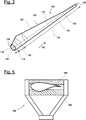
- FIG. 2 shows an exemplary wind turbine rotor blade 110.
- the rotor blade 110 has the shape of a conventional rotor blade and has a rotor blade root region 114 which faces or is assigned to the rotor hub 112.
- the rotor blade root region 114 typically has a substantially circular cross section.
- a transition area 116 and a profile area 118 of the rotor blade 110 adjoin the rotor blade root area 114.
- the rotor blade 110 has a longitudinal axis 120 as well as a pressure side 122 and an opposite suction side 124.
- the interior of the rotor blade 110 is essentially hollow.
- the rotor blade 110 has an end 126 on the blade root side and an end 128 on the blade tip side.
- the rotor blade 110 has a profile nose edge 130 and a profile end edge 132.
- FIG. 3 schematically shows a transport system 134 in a schematic side view according to an embodiment of the invention.
- the transport vehicle 134 is a heavy-duty transport vehicle for the transport of a wind energy installation rotor blade 110.
- the transport system 134 has a tractor 136 and a trailer vehicle 138.
- the tractor 136 corresponds, for example, to a conventional truck tractor and has its own drive, for example a motor.
- a front bearing device 140 for fixing the rotor blade 110 is arranged on the tractor 136.
- the rotor blade 110 is with its blade root side End 126 fixedly mounted on the front bearing device 140 in the intended state.
- the rotor blade 110 is supported on the trailer vehicle 138.
- the trailer vehicle 138 has a rear bearing device 144.
- the trailer vehicle 118 is a vehicle with several axles, which is equipped without its own drive. Because the rotor blade 110 is firmly mechanically connected to the trailer vehicle 138, the trailer vehicle is pulled along by the drive of the tractor 136.
- the trailer vehicle 138 has a chassis 146 which comprises a chassis with axles and wheels attached to it.
- a pivot and / or rocker bearing 148 (hereinafter pivot bearing 148) is fixedly arranged on the chassis 146.
- the pivot bearing 148 is firmly connected via a frame table 150 to the rear bearing device 144, which is formed by two rear bearing or holding frames 152.
- the rear holding frames 152 represent two receiving points or mounting points for the rotor blade 110.
- the rotor blade 110 is firmly connected to the holding frames 152 in the properly stored state.
- the holding frames 152 can, but do not have to be, permanently connected directly to one another.
- the holding frames 152 are indirectly mechanically connected via the frame table 150.
- the transport system 134 has a stiffening device 154.
- the stiffening device 154 has a first coupling device 156 and a second coupling device 158.
- the first coupling device 156 is designed as a vertical holding frame 157 and is related to the Longitudinal axis 120 (see Figure 2 , not in Figure 3 shown) in a half facing the root end 126. Vertical means that a main direction of extent of the holding frame runs vertically. A vertical direction V is in Figure 3 drawn.
- the first coupling device 156 is firmly connected to the rotor blade 110 and forms a rigid unit with it.
- FIG Figure 5 An exemplary support frame 156 is shown in FIG Figure 5 shown.
- the holding frame 156 has two receiving shells 160 which are at least partially adapted to a shape of the rotor blade 110 and which enclose it.
- the second coupling device 158 is also designed as a vertical holding frame, which is part of the rear bearing device 144.
- the first coupling device 156 is mechanically connected to the front bearing device 140 via one or more first beams or support beams 162 (generally holding structures).
- the stiffening device 154 also has vertical (intermediate) holding frames 164 which are arranged between the two coupling devices 156, 158 and which are each firmly connected to the rotor blade 110.
- the two coupling devices 156, 158 and the intermediate holding frames 164 are mechanically connected in the manner of a framework via horizontal second beams 166 (also connecting beams) and third, obliquely arranged beams 168, which are also part of the stiffening device 154.
- the connections are articulated.
- the illustrated second and third bars 166, 168 can all or in part be duplicated, that is to say on the front shown as well as mirrored on the back, not shown.
- the diagonal bars 168 can also be designed as loaded cables or loaded bars (tension cables or tension rods). The orientation of such diagonal bars 168 is carried out, for example, in the opposite direction.
- the second and third beams 166, 168 and the intermediate holding frames 164 represent a connecting means 170 of the stiffening device 154, which mechanically connects the two coupling devices 156, 158.
- the second beams 166 can be coupled to one another directly or indirectly via the holding frames 164.
- the rotor blade 110 together with the stiffening device 154 forms a stiffened unit, as explained at the beginning.
- the rotor blade 110 is mounted between the coupling device 156, 158 in such a way that at least the connecting means 170 is subjected to tensile stress.
- the second beams 166 are subjected to tensile loads and absorb forces which arise from a bending of the blade 110 and which would push the two coupling devices 156, 158 apart.
- a zero line 172 (see Figure 2 ) of the rotor blade 110 at least partially between the coupling devices 156, 158 a curvature against the direction of gravity, that is, a curvature away from a substrate 174 (curvature in Figure 3 not shown for reasons of clarity).
- the rotor blade 110 is stiffened between the two coupling devices 156, 158 and bending of the blade 110 is avoided or at least reduced to a structurally sensible amount.
- the coupling devices 156, 158 and the intermediate holding frames 164 have a vertical height 176 which corresponds approximately to a diameter 178 of the rotor blade 110 at the end 126 on the root side.
- the height 176 of the frames or coupling devices can be different and / or smaller.
- Coupling points 180 and 182, at which the connecting means 170, that is to say the second beams 166, engage the first and second coupling devices 156, 158, respectively, are well below the rotor blade 110, in particular below the zero line 172. This promotes the stiffening effect and is in particular advantageous in terms of the forces acting.
- Figure 4 shows a slightly modified form of the Figure 3 described embodiment. For the sake of clarity, therefore, all reference numerals of the Figure 3 in Figure 4 to represent again.
- the rear storage device 144 of the following vehicle 138 is not designed as a double frame, but only has a rear holding frame 152, which functions as a second coupling device 158 analogously to above. The functionality is the same as above.
- the second and third bars 166, 168 attack a rear bearing frame 152 in order to be indirectly fixedly connected to the rotor blade 110 in the area on the blade tip side.
- the connecting means 170 with or without a third beam 168 could act on the frame table 150, which in turn is rigidly connected to a rear holding frame 152 and thus fixed to the rotor blade 110 is connected.
- the coupling to the first coupling device 156 other configurations are also conceivable. As mentioned at the beginning, the first coupling device 156 could not be designed as a holding frame, but rather be part of the front bearing device 140.
- the first coupling device 156 in this case is designed as a fastening element which enables coupling to the connecting means 170, for example a second beam 166.
- the second coupling device 158 which does not necessarily have to be part of the rear bearing device 144, but, like the first coupling device 156, can be designed as a holding frame which is located between the rear bearing device 144 and a center of the sheet 110 (with respect to the longitudinal axis 120 ) is arranged. It is common to all embodiments that the rotor blade 110 is part of the stiffening unit.
- Figure 6 shows a further embodiment of a transport system 134, which is based on the embodiments Figures 3 and 4 is very similar.
- the same reference symbols are used for functionally or structurally identical elements.
- the transport system 134 is constructed analogously to the above and has a first and a second coupling device 156, 158.
- the two coupling devices 156, 158 are not connected via bars 166, 168 and intermediate holding frames 164, but rather via one or more ropes that form the connecting means 170.
- it is one or more steel cables.
- the connecting means 170 mechanically connects the two coupling devices 156, 158, so that when the rotor blade 110 is properly mounted, a stiffening is again formed is, in which the connecting means 170 is tensioned and prevents harmful bending of the rotor blade 110 as above.
- Figure 7 shows a slightly modified form of the Figure 6 described embodiment. For the sake of clarity, therefore, all reference numerals of the Figure 6 in Figure 7 to represent again.
- the rear storage device 144 of the following vehicle 138 is not designed as a double frame, but only has a rear holding frame 152, which functions as a second coupling device 158 analogously to above. The functionality is the same as above.
- the coupling devices 156, 158, the connecting means 170 and the bars 162, 166 and 168 are all or in part made of metallic materials or fiber composite materials. The lighter the elements, the more effective.
- FIG. 11 shows a schematic flow diagram of a method for transporting a rotor blade 110.
- a first step S1 the end 126 of the wind turbine rotor blade 110 on the blade root side is fixed on the front bearing device 140.
- a next step S2 the rear, blade tip-side region 142 of the wind turbine rotor blade 110 is fixed on the rear bearing device 144 of the trailer vehicle 138.
- Steps S1 and S2 can also be interchanged.
- the stiffening device 154 for the wind energy installation rotor blade 110 is provided and installed.
- the stiffening device comprises the first coupling device 156, the second coupling device 158 and the connecting means 170.
- the first coupling device 156 is firmly connected to the wind energy installation rotor blade 110 in a front, blade root-side area of the wind energy installation rotor blade 110 in relation to the longitudinal axis 120 of the wind energy installation rotor blade 110.
- the second coupling device 158 which in the exemplary embodiments of FIG Figures 3 to 7 Part of the rear bearing device 144 is already firmly connected to the wind turbine rotor blade 110. Otherwise, the second coupling device 158 would have to be attached in a further step.
- a next step S5 the two coupling devices 156, 158 are connected to one another by means of the connecting means 170 in such a way that the connecting means 170 is subjected to tensile loading.
Landscapes
- Engineering & Computer Science (AREA)
- Mechanical Engineering (AREA)
- Life Sciences & Earth Sciences (AREA)
- Sustainable Development (AREA)
- Sustainable Energy (AREA)
- Chemical & Material Sciences (AREA)
- Combustion & Propulsion (AREA)
- General Engineering & Computer Science (AREA)
- Health & Medical Sciences (AREA)
- Public Health (AREA)
- Transportation (AREA)
- Wind Motors (AREA)
Priority Applications (3)
| Application Number | Priority Date | Filing Date | Title |
|---|---|---|---|
| EP19175715.2A EP3741992B1 (fr) | 2019-05-21 | 2019-05-21 | Système de transport pour une pale de rotor d'éolienne |
| DK19175715.2T DK3741992T3 (da) | 2019-05-21 | 2019-05-21 | Transportsystem til et vindenergianlægsrotorblad |
| ES19175715T ES2942156T3 (es) | 2019-05-21 | 2019-05-21 | Sistema de transporte para una pala de rotor de turbina eólica |
Applications Claiming Priority (1)
| Application Number | Priority Date | Filing Date | Title |
|---|---|---|---|
| EP19175715.2A EP3741992B1 (fr) | 2019-05-21 | 2019-05-21 | Système de transport pour une pale de rotor d'éolienne |
Publications (2)
| Publication Number | Publication Date |
|---|---|
| EP3741992A1 true EP3741992A1 (fr) | 2020-11-25 |
| EP3741992B1 EP3741992B1 (fr) | 2023-01-11 |
Family
ID=66630127
Family Applications (1)
| Application Number | Title | Priority Date | Filing Date |
|---|---|---|---|
| EP19175715.2A Active EP3741992B1 (fr) | 2019-05-21 | 2019-05-21 | Système de transport pour une pale de rotor d'éolienne |
Country Status (3)
| Country | Link |
|---|---|
| EP (1) | EP3741992B1 (fr) |
| DK (1) | DK3741992T3 (fr) |
| ES (1) | ES2942156T3 (fr) |
Cited By (1)
| Publication number | Priority date | Publication date | Assignee | Title |
|---|---|---|---|---|
| CN115324837A (zh) * | 2022-09-08 | 2022-11-11 | 山东京九重工股份有限公司 | 一种用于大型风力发电叶片专用运输车 |
Citations (4)
| Publication number | Priority date | Publication date | Assignee | Title |
|---|---|---|---|---|
| WO2006000230A1 (fr) * | 2004-06-29 | 2006-01-05 | Vamdrup Specialtransport Aps | Procede et vehicule permettant le transport d'une longue pale d'eolienne |
| WO2014072042A2 (fr) * | 2012-11-06 | 2014-05-15 | Scheuerle Fahrzeugfabrik Gmbh | Véhicule de transport de charges lourdes servant au transport d'un objet allongé |
| KR101614493B1 (ko) * | 2015-06-11 | 2016-04-21 | 김병연 | 풍력발전기용 블레이드 전후축 이동 트레일러 |
| US9790927B1 (en) * | 2016-08-04 | 2017-10-17 | Bnsf Logistics, Llc | Wind turbine blade double pivot transportation system and method |
-
2019
- 2019-05-21 DK DK19175715.2T patent/DK3741992T3/da active
- 2019-05-21 ES ES19175715T patent/ES2942156T3/es active Active
- 2019-05-21 EP EP19175715.2A patent/EP3741992B1/fr active Active
Patent Citations (5)
| Publication number | Priority date | Publication date | Assignee | Title |
|---|---|---|---|---|
| WO2006000230A1 (fr) * | 2004-06-29 | 2006-01-05 | Vamdrup Specialtransport Aps | Procede et vehicule permettant le transport d'une longue pale d'eolienne |
| EP2105349A1 (fr) | 2004-06-29 | 2009-09-30 | Vamdrup Specialtransport APS | Véhicule non propulsée permettant le transport d'une longue pale d'eolienne |
| WO2014072042A2 (fr) * | 2012-11-06 | 2014-05-15 | Scheuerle Fahrzeugfabrik Gmbh | Véhicule de transport de charges lourdes servant au transport d'un objet allongé |
| KR101614493B1 (ko) * | 2015-06-11 | 2016-04-21 | 김병연 | 풍력발전기용 블레이드 전후축 이동 트레일러 |
| US9790927B1 (en) * | 2016-08-04 | 2017-10-17 | Bnsf Logistics, Llc | Wind turbine blade double pivot transportation system and method |
Cited By (1)
| Publication number | Priority date | Publication date | Assignee | Title |
|---|---|---|---|---|
| CN115324837A (zh) * | 2022-09-08 | 2022-11-11 | 山东京九重工股份有限公司 | 一种用于大型风力发电叶片专用运输车 |
Also Published As
| Publication number | Publication date |
|---|---|
| DK3741992T3 (da) | 2023-04-17 |
| EP3741992B1 (fr) | 2023-01-11 |
| ES2942156T3 (es) | 2023-05-30 |
Similar Documents
| Publication | Publication Date | Title |
|---|---|---|
| EP2416986B1 (fr) | Dispositif de transport | |
| DE102010014302B4 (de) | Luftfahrzeug und Befestigungsanordnung für eine Fußbodenstruktur in einem Luftfahrzeug | |
| EP2764237B1 (fr) | Procédé et dispositif de montage d'un rotor d'une éolienne | |
| EP1600362A1 (fr) | Structure de plancher pour véhicule automobile | |
| DE102005003296B4 (de) | Rumpfhecksektion eines Flugzeugs | |
| DE102009011478A1 (de) | Handhabungsvorrichtung für Rotorblattlager | |
| DE102012205090A1 (de) | Getriebelagerung einer Windenergieanlage, Windenergieanlage und Verfahren zum Warten einer Getriebelagerung | |
| WO2012175171A1 (fr) | Dispositif de manutention de charges pour le levage et procédé de montage de pales de rotor d'un aérogénérateur | |
| EP2090462A2 (fr) | Châssis de conteneur réglable en longueur | |
| DE102014105356A1 (de) | Mobile Kranvorrichtung sowie Verfahren zur temporären Montage einer solchen Kranvorrichtung | |
| EP3841054A1 (fr) | Grue | |
| WO2014023277A1 (fr) | Dispositif de transport surélevé comportant une charpente porteuse auto-porteuse | |
| DE102007058553A1 (de) | Seitliche Abspannung für einen Gitterausleger eines Kranes | |
| DE102009020896B4 (de) | Flugkörper | |
| DE102015006117A1 (de) | Verfahren zum Betrieb eines Krans und Kran | |
| EP3741992B1 (fr) | Système de transport pour une pale de rotor d'éolienne | |
| DE202013105503U1 (de) | Flugzeugrumpf | |
| DE102011119655A1 (de) | Kran | |
| EP3319898B1 (fr) | Grue à tour | |
| DE102009017068B4 (de) | Transportvorrichtung | |
| DE102007009402B4 (de) | Wippausleger-Turmdrehkran | |
| EP3584114B1 (fr) | Véhicule remorque pour le transport d'une pale de rotor d'une éolienne, dispositif de déplacement pour un véhicule remorque, véhicule de transport ainsi que procédé | |
| DE4031663A1 (de) | Fachwerk-dachkonstruktion | |
| DE102020118713A1 (de) | Verfahren zum Herstellen einer Windenergieanlage, Windenergieanlage sowie Torsionsaufnahme | |
| DE102005045446B4 (de) | Fahrwerksträger eines Fahrwerks, insbesondere für einen Kran |
Legal Events
| Date | Code | Title | Description |
|---|---|---|---|
| PUAI | Public reference made under article 153(3) epc to a published international application that has entered the european phase |
Free format text: ORIGINAL CODE: 0009012 |
|
| STAA | Information on the status of an ep patent application or granted ep patent |
Free format text: STATUS: THE APPLICATION HAS BEEN PUBLISHED |
|
| AK | Designated contracting states |
Kind code of ref document: A1 Designated state(s): AL AT BE BG CH CY CZ DE DK EE ES FI FR GB GR HR HU IE IS IT LI LT LU LV MC MK MT NL NO PL PT RO RS SE SI SK SM TR |
|
| RAP3 | Party data changed (applicant data changed or rights of an application transferred) |
Owner name: NORDEX ENERGY SE & CO. KG |
|
| STAA | Information on the status of an ep patent application or granted ep patent |
Free format text: STATUS: REQUEST FOR EXAMINATION WAS MADE |
|
| 17P | Request for examination filed |
Effective date: 20210503 |
|
| RBV | Designated contracting states (corrected) |
Designated state(s): AL AT BE BG CH CY CZ DE DK EE ES FI FR GB GR HR HU IE IS IT LI LT LU LV MC MK MT NL NO PL PT RO RS SE SI SK SM TR |
|
| GRAP | Despatch of communication of intention to grant a patent |
Free format text: ORIGINAL CODE: EPIDOSNIGR1 |
|
| STAA | Information on the status of an ep patent application or granted ep patent |
Free format text: STATUS: GRANT OF PATENT IS INTENDED |
|
| RIC1 | Information provided on ipc code assigned before grant |
Ipc: B60P 3/40 20060101ALI20220819BHEP Ipc: F03D 13/40 20160101AFI20220819BHEP |
|
| INTG | Intention to grant announced |
Effective date: 20220905 |
|
| GRAS | Grant fee paid |
Free format text: ORIGINAL CODE: EPIDOSNIGR3 |
|
| GRAA | (expected) grant |
Free format text: ORIGINAL CODE: 0009210 |
|
| STAA | Information on the status of an ep patent application or granted ep patent |
Free format text: STATUS: THE PATENT HAS BEEN GRANTED |
|
| AK | Designated contracting states |
Kind code of ref document: B1 Designated state(s): AL AT BE BG CH CY CZ DE DK EE ES FI FR GB GR HR HU IE IS IT LI LT LU LV MC MK MT NL NO PL PT RO RS SE SI SK SM TR |
|
| REG | Reference to a national code |
Ref country code: GB Ref legal event code: FG4D Free format text: NOT ENGLISH |
|
| REG | Reference to a national code |
Ref country code: CH Ref legal event code: EP |
|
| REG | Reference to a national code |
Ref country code: DE Ref legal event code: R096 Ref document number: 502019006744 Country of ref document: DE |
|
| REG | Reference to a national code |
Ref country code: IE Ref legal event code: FG4D Free format text: LANGUAGE OF EP DOCUMENT: GERMAN |
|
| REG | Reference to a national code |
Ref country code: AT Ref legal event code: REF Ref document number: 1543573 Country of ref document: AT Kind code of ref document: T Effective date: 20230215 |
|
| REG | Reference to a national code |
Ref country code: DK Ref legal event code: T3 Effective date: 20230411 |
|
| REG | Reference to a national code |
Ref country code: LT Ref legal event code: MG9D |
|
| REG | Reference to a national code |
Ref country code: NL Ref legal event code: MP Effective date: 20230111 |
|
| REG | Reference to a national code |
Ref country code: ES Ref legal event code: FG2A Ref document number: 2942156 Country of ref document: ES Kind code of ref document: T3 Effective date: 20230530 |
|
| P01 | Opt-out of the competence of the unified patent court (upc) registered |
Effective date: 20230515 |
|
| PG25 | Lapsed in a contracting state [announced via postgrant information from national office to epo] |
Ref country code: NL Free format text: LAPSE BECAUSE OF FAILURE TO SUBMIT A TRANSLATION OF THE DESCRIPTION OR TO PAY THE FEE WITHIN THE PRESCRIBED TIME-LIMIT Effective date: 20230111 |
|
| PG25 | Lapsed in a contracting state [announced via postgrant information from national office to epo] |
Ref country code: RS Free format text: LAPSE BECAUSE OF FAILURE TO SUBMIT A TRANSLATION OF THE DESCRIPTION OR TO PAY THE FEE WITHIN THE PRESCRIBED TIME-LIMIT Effective date: 20230111 Ref country code: PT Free format text: LAPSE BECAUSE OF FAILURE TO SUBMIT A TRANSLATION OF THE DESCRIPTION OR TO PAY THE FEE WITHIN THE PRESCRIBED TIME-LIMIT Effective date: 20230511 Ref country code: NO Free format text: LAPSE BECAUSE OF FAILURE TO SUBMIT A TRANSLATION OF THE DESCRIPTION OR TO PAY THE FEE WITHIN THE PRESCRIBED TIME-LIMIT Effective date: 20230411 Ref country code: LV Free format text: LAPSE BECAUSE OF FAILURE TO SUBMIT A TRANSLATION OF THE DESCRIPTION OR TO PAY THE FEE WITHIN THE PRESCRIBED TIME-LIMIT Effective date: 20230111 Ref country code: LT Free format text: LAPSE BECAUSE OF FAILURE TO SUBMIT A TRANSLATION OF THE DESCRIPTION OR TO PAY THE FEE WITHIN THE PRESCRIBED TIME-LIMIT Effective date: 20230111 Ref country code: HR Free format text: LAPSE BECAUSE OF FAILURE TO SUBMIT A TRANSLATION OF THE DESCRIPTION OR TO PAY THE FEE WITHIN THE PRESCRIBED TIME-LIMIT Effective date: 20230111 |
|
| PG25 | Lapsed in a contracting state [announced via postgrant information from national office to epo] |
Ref country code: SE Free format text: LAPSE BECAUSE OF FAILURE TO SUBMIT A TRANSLATION OF THE DESCRIPTION OR TO PAY THE FEE WITHIN THE PRESCRIBED TIME-LIMIT Effective date: 20230111 Ref country code: PL Free format text: LAPSE BECAUSE OF FAILURE TO SUBMIT A TRANSLATION OF THE DESCRIPTION OR TO PAY THE FEE WITHIN THE PRESCRIBED TIME-LIMIT Effective date: 20230111 Ref country code: IS Free format text: LAPSE BECAUSE OF FAILURE TO SUBMIT A TRANSLATION OF THE DESCRIPTION OR TO PAY THE FEE WITHIN THE PRESCRIBED TIME-LIMIT Effective date: 20230511 Ref country code: GR Free format text: LAPSE BECAUSE OF FAILURE TO SUBMIT A TRANSLATION OF THE DESCRIPTION OR TO PAY THE FEE WITHIN THE PRESCRIBED TIME-LIMIT Effective date: 20230412 Ref country code: FI Free format text: LAPSE BECAUSE OF FAILURE TO SUBMIT A TRANSLATION OF THE DESCRIPTION OR TO PAY THE FEE WITHIN THE PRESCRIBED TIME-LIMIT Effective date: 20230111 |
|
| REG | Reference to a national code |
Ref country code: DE Ref legal event code: R097 Ref document number: 502019006744 Country of ref document: DE |
|
| PG25 | Lapsed in a contracting state [announced via postgrant information from national office to epo] |
Ref country code: SM Free format text: LAPSE BECAUSE OF FAILURE TO SUBMIT A TRANSLATION OF THE DESCRIPTION OR TO PAY THE FEE WITHIN THE PRESCRIBED TIME-LIMIT Effective date: 20230111 Ref country code: RO Free format text: LAPSE BECAUSE OF FAILURE TO SUBMIT A TRANSLATION OF THE DESCRIPTION OR TO PAY THE FEE WITHIN THE PRESCRIBED TIME-LIMIT Effective date: 20230111 Ref country code: EE Free format text: LAPSE BECAUSE OF FAILURE TO SUBMIT A TRANSLATION OF THE DESCRIPTION OR TO PAY THE FEE WITHIN THE PRESCRIBED TIME-LIMIT Effective date: 20230111 Ref country code: CZ Free format text: LAPSE BECAUSE OF FAILURE TO SUBMIT A TRANSLATION OF THE DESCRIPTION OR TO PAY THE FEE WITHIN THE PRESCRIBED TIME-LIMIT Effective date: 20230111 |
|
| PLBE | No opposition filed within time limit |
Free format text: ORIGINAL CODE: 0009261 |
|
| STAA | Information on the status of an ep patent application or granted ep patent |
Free format text: STATUS: NO OPPOSITION FILED WITHIN TIME LIMIT |
|
| PG25 | Lapsed in a contracting state [announced via postgrant information from national office to epo] |
Ref country code: SK Free format text: LAPSE BECAUSE OF FAILURE TO SUBMIT A TRANSLATION OF THE DESCRIPTION OR TO PAY THE FEE WITHIN THE PRESCRIBED TIME-LIMIT Effective date: 20230111 |
|
| 26N | No opposition filed |
Effective date: 20231012 |
|
| REG | Reference to a national code |
Ref country code: CH Ref legal event code: PL |
|
| PG25 | Lapsed in a contracting state [announced via postgrant information from national office to epo] |
Ref country code: MC Free format text: LAPSE BECAUSE OF FAILURE TO SUBMIT A TRANSLATION OF THE DESCRIPTION OR TO PAY THE FEE WITHIN THE PRESCRIBED TIME-LIMIT Effective date: 20230111 |
|
| GBPC | Gb: european patent ceased through non-payment of renewal fee |
Effective date: 20230521 |
|
| REG | Reference to a national code |
Ref country code: BE Ref legal event code: MM Effective date: 20230531 |
|
| PG25 | Lapsed in a contracting state [announced via postgrant information from national office to epo] |
Ref country code: SI Free format text: LAPSE BECAUSE OF FAILURE TO SUBMIT A TRANSLATION OF THE DESCRIPTION OR TO PAY THE FEE WITHIN THE PRESCRIBED TIME-LIMIT Effective date: 20230111 Ref country code: MC Free format text: LAPSE BECAUSE OF FAILURE TO SUBMIT A TRANSLATION OF THE DESCRIPTION OR TO PAY THE FEE WITHIN THE PRESCRIBED TIME-LIMIT Effective date: 20230111 Ref country code: LU Free format text: LAPSE BECAUSE OF NON-PAYMENT OF DUE FEES Effective date: 20230521 Ref country code: LI Free format text: LAPSE BECAUSE OF NON-PAYMENT OF DUE FEES Effective date: 20230531 Ref country code: CH Free format text: LAPSE BECAUSE OF NON-PAYMENT OF DUE FEES Effective date: 20230531 |
|
| REG | Reference to a national code |
Ref country code: IE Ref legal event code: MM4A |
|
| PG25 | Lapsed in a contracting state [announced via postgrant information from national office to epo] |
Ref country code: IE Free format text: LAPSE BECAUSE OF NON-PAYMENT OF DUE FEES Effective date: 20230521 |
|
| PG25 | Lapsed in a contracting state [announced via postgrant information from national office to epo] |
Ref country code: IE Free format text: LAPSE BECAUSE OF NON-PAYMENT OF DUE FEES Effective date: 20230521 Ref country code: GB Free format text: LAPSE BECAUSE OF NON-PAYMENT OF DUE FEES Effective date: 20230521 |
|
| PG25 | Lapsed in a contracting state [announced via postgrant information from national office to epo] |
Ref country code: IT Free format text: LAPSE BECAUSE OF FAILURE TO SUBMIT A TRANSLATION OF THE DESCRIPTION OR TO PAY THE FEE WITHIN THE PRESCRIBED TIME-LIMIT Effective date: 20230111 Ref country code: FR Free format text: LAPSE BECAUSE OF NON-PAYMENT OF DUE FEES Effective date: 20230531 Ref country code: BE Free format text: LAPSE BECAUSE OF NON-PAYMENT OF DUE FEES Effective date: 20230531 |
|
| PGFP | Annual fee paid to national office [announced via postgrant information from national office to epo] |
Ref country code: DE Payment date: 20240517 Year of fee payment: 6 |
|
| PGFP | Annual fee paid to national office [announced via postgrant information from national office to epo] |
Ref country code: DK Payment date: 20240522 Year of fee payment: 6 |
|
| PGFP | Annual fee paid to national office [announced via postgrant information from national office to epo] |
Ref country code: ES Payment date: 20240614 Year of fee payment: 6 |