EP3741284A1 - Dishwasher with an image acquisition device and method for operating such a dishwasher - Google Patents
Dishwasher with an image acquisition device and method for operating such a dishwasher Download PDFInfo
- Publication number
- EP3741284A1 EP3741284A1 EP20173603.0A EP20173603A EP3741284A1 EP 3741284 A1 EP3741284 A1 EP 3741284A1 EP 20173603 A EP20173603 A EP 20173603A EP 3741284 A1 EP3741284 A1 EP 3741284A1
- Authority
- EP
- European Patent Office
- Prior art keywords
- dishwasher
- spray arm
- image
- camera
- signal
- Prior art date
- Legal status (The legal status is an assumption and is not a legal conclusion. Google has not performed a legal analysis and makes no representation as to the accuracy of the status listed.)
- Granted
Links
- 238000000034 method Methods 0.000 title claims abstract description 25
- 239000007921 spray Substances 0.000 claims abstract description 45
- 238000005406 washing Methods 0.000 claims abstract description 35
- 238000004140 cleaning Methods 0.000 claims abstract 3
- 238000011156 evaluation Methods 0.000 claims description 8
- 238000001454 recorded image Methods 0.000 claims description 2
- 230000003213 activating effect Effects 0.000 claims 1
- 230000000903 blocking effect Effects 0.000 description 3
- 239000007788 liquid Substances 0.000 description 3
- 230000008878 coupling Effects 0.000 description 2
- 238000010168 coupling process Methods 0.000 description 2
- 238000005859 coupling reaction Methods 0.000 description 2
- 238000011010 flushing procedure Methods 0.000 description 2
- 239000012459 cleaning agent Substances 0.000 description 1
- 230000001419 dependent effect Effects 0.000 description 1
- 238000001514 detection method Methods 0.000 description 1
- 238000011161 development Methods 0.000 description 1
- 230000018109 developmental process Effects 0.000 description 1
- 230000003287 optical effect Effects 0.000 description 1
- 235000014347 soups Nutrition 0.000 description 1
Images


Classifications
-
- A—HUMAN NECESSITIES
- A47—FURNITURE; DOMESTIC ARTICLES OR APPLIANCES; COFFEE MILLS; SPICE MILLS; SUCTION CLEANERS IN GENERAL
- A47L—DOMESTIC WASHING OR CLEANING; SUCTION CLEANERS IN GENERAL
- A47L15/00—Washing or rinsing machines for crockery or tableware
- A47L15/42—Details
- A47L15/4295—Arrangements for detecting or measuring the condition of the crockery or tableware, e.g. nature or quantity
-
- A—HUMAN NECESSITIES
- A47—FURNITURE; DOMESTIC ARTICLES OR APPLIANCES; COFFEE MILLS; SPICE MILLS; SUCTION CLEANERS IN GENERAL
- A47L—DOMESTIC WASHING OR CLEANING; SUCTION CLEANERS IN GENERAL
- A47L15/00—Washing or rinsing machines for crockery or tableware
- A47L15/0018—Controlling processes, i.e. processes to control the operation of the machine characterised by the purpose or target of the control
-
- A—HUMAN NECESSITIES
- A47—FURNITURE; DOMESTIC ARTICLES OR APPLIANCES; COFFEE MILLS; SPICE MILLS; SUCTION CLEANERS IN GENERAL
- A47L—DOMESTIC WASHING OR CLEANING; SUCTION CLEANERS IN GENERAL
- A47L15/00—Washing or rinsing machines for crockery or tableware
- A47L15/14—Washing or rinsing machines for crockery or tableware with stationary crockery baskets and spraying devices within the cleaning chamber
- A47L15/18—Washing or rinsing machines for crockery or tableware with stationary crockery baskets and spraying devices within the cleaning chamber with movably-mounted spraying devices
- A47L15/22—Rotary spraying devices
- A47L15/23—Rotary spraying devices moved by means of the sprays
-
- A—HUMAN NECESSITIES
- A47—FURNITURE; DOMESTIC ARTICLES OR APPLIANCES; COFFEE MILLS; SPICE MILLS; SUCTION CLEANERS IN GENERAL
- A47L—DOMESTIC WASHING OR CLEANING; SUCTION CLEANERS IN GENERAL
- A47L15/00—Washing or rinsing machines for crockery or tableware
- A47L15/0018—Controlling processes, i.e. processes to control the operation of the machine characterised by the purpose or target of the control
- A47L15/0049—Detection or prevention of malfunction, including accident prevention
-
- A—HUMAN NECESSITIES
- A47—FURNITURE; DOMESTIC ARTICLES OR APPLIANCES; COFFEE MILLS; SPICE MILLS; SUCTION CLEANERS IN GENERAL
- A47L—DOMESTIC WASHING OR CLEANING; SUCTION CLEANERS IN GENERAL
- A47L2401/00—Automatic detection in controlling methods of washing or rinsing machines for crockery or tableware, e.g. information provided by sensors entered into controlling devices
- A47L2401/24—Spray arms status, e.g. detection of spray arm rotation
-
- A—HUMAN NECESSITIES
- A47—FURNITURE; DOMESTIC ARTICLES OR APPLIANCES; COFFEE MILLS; SPICE MILLS; SUCTION CLEANERS IN GENERAL
- A47L—DOMESTIC WASHING OR CLEANING; SUCTION CLEANERS IN GENERAL
- A47L2501/00—Output in controlling method of washing or rinsing machines for crockery or tableware, i.e. quantities or components controlled, or actions performed by the controlling device executing the controlling method
- A47L2501/26—Indication or alarm to the controlling device or to the user
-
- A—HUMAN NECESSITIES
- A47—FURNITURE; DOMESTIC ARTICLES OR APPLIANCES; COFFEE MILLS; SPICE MILLS; SUCTION CLEANERS IN GENERAL
- A47L—DOMESTIC WASHING OR CLEANING; SUCTION CLEANERS IN GENERAL
- A47L2501/00—Output in controlling method of washing or rinsing machines for crockery or tableware, i.e. quantities or components controlled, or actions performed by the controlling device executing the controlling method
- A47L2501/36—Other output
Definitions
- the invention relates to a method for operating a dishwasher, in particular a domestic dishwasher, wherein the dishwasher is used to clean items to be washed in a washing area and has an image acquisition device for recording images of the washing area.
- the invention also relates to such a dishwasher.
- a camera image created before or during a running cleaning program is evaluated in order to determine the degree of soiling of the items to be washed.
- a washing program optimized for the degree of soiling can be set under computer control, or a set washing program can be optimized with regard to the degree of soiling.
- a speed of one or more spray arms visible on the camera image is determined from an evaluation of video recordings of the camera from the wash cabinet.
- the spray arm is usually disruptive in the camera image from the washing area of a dishwasher. It has been shown that camera recordings appear particularly blurry when the spray arm is in operation and is close to the lens of the camera when the image is recorded.
- a method according to the invention of the type mentioned at the beginning comprises the following steps: A signal from a sensor which is coupled to a spray arm of the dishwasher is evaluated, the signal reflecting a rotation of the spray arm. Then an image of the washing area is recorded by the image acquisition device as a function of the evaluated signal.
- the signal from the sensor is thus used to control the image acquisition device, e.g. a camera to instruct at an optimal time to take a picture of the wash cabinet.
- the image acquisition device e.g. a camera to instruct at an optimal time to take a picture of the wash cabinet.
- One embodiment of the method provides for the image to be recorded at a specific angle of rotation of the spray arm.
- camera recordings are only made when the spray arm is in certain rotational positions in which it affects the camera image as little as possible. In this way, details from the wash cabinet become more visible and an evaluation, e.g. to determine a load in the dishwasher or a degree of soiling of the items to be washed can be carried out more reliably in an automated manner.
- Another embodiment of the method provides for the image to be recorded when the signal indicates that the spray arm is not rotating, that is, when a blockage of the spray arm is detected via the sensor.
- a blockage leads to an inadequate wash result because the wash liquor is not optimally distributed in the wash cabinet.
- the captured image visualizes the cause of the blockage.
- the combination of image acquisition device and sensor according to the application can advantageously be used in order to show such a blockage to a user of the dishwasher in such a way that he can remove it quickly and without problems.
- a data message is sent from the control device of the dishwasher to a mobile device when the signal indicates that the spray arm is not rotating.
- the captured image or at least a section of it can be transmitted to the mobile device in order to be able to present it to the user and thus show details of the blocking.
- a dishwasher according to the invention is characterized in that, in addition to the image acquisition device, which e.g. can be designed as a camera, additionally has a sensor with which a rotation of a spray arm can be detected, wherein the sensor is connected to the control device for evaluation and wherein the control device is set up to control the image acquisition device depending on a signal from the sensor.
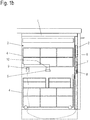
- the Figures 1a and b each show schematically a dishwasher in a vertical sectional view.
- the dishwasher which can be a domestic appliance as well as a machine for professional use, has a body 1 with a door 2 which surrounds a washing area 3.
- a washing area 3 As a rule, several, here for example two washware baskets 4 are arranged one above the other within the washing space 3.
- Various items can be sorted into the washware baskets 4.
- a cutlery basket can be present in one of the washware baskets 4 instead of or in addition to the cutlery holder.
- the wash baskets 4 are each assigned a spray arm which rotates in the washing mode and sprays washing liquid onto the wash ware.
- only one spray arm 5 assigned to the upper washware basket 4 is shown.
- the two Figures 1a and b show the spray arm 5 in two different rotational positions at an angle of 90 ° to one another.
- washing liquid collects in a washing sump, also called washing liquor pot, in which it can be heated and pumped to the spray arms 5.
- washing sump also called washing liquor pot
- the flushing sump and components for circulating the flushing liquid are shown in the schematic drawing of FIG Figure 1 not reproduced.
- a control device 6 for controlling the dishwasher is arranged in the door 2 of the dishwasher.
- the control device 6 is designed as a sequence control based on a microcontroller or microprocessor.
- a dosing unit 7 with which the required cleaning agent can be automatically dosed into the washing area 3 during a washing process.
- a camera 8 is integrated into the dosing unit 7 as an image acquisition device, which is directed into the washing chamber 3 in order to record an image of the washing chamber 3.
- a light source 9 is arranged in the washing area 3, which light source can be switched on as required when an image of the washing area 3 is recorded by the camera 8.
- a light source can also be arranged in the area of the camera 8 itself, which light source is designed, for example, in a ring around an objective of the camera 8.
- the camera 8 is a two-dimensionally recording camera.
- a three-dimensional recording camera can also be used, for example a TOF (time of flight) camera that takes light transit times into account.
- An arrangement of two cameras that records stereoscopically is also considered an image acquisition device in the context of the application.
- only one camera 8 is present, which essentially captures the items to be washed in the lower washware basket 4.
- a further camera can be present, which is arranged, for example, above the camera 8 shown and is directed at the items to be washed in the upper washware basket 4.
- the recording direction (optical axis) of the camera 8 is aligned horizontally.
- Other orientations of the camera 8 are conceivable.
- the spray arm 5 is coupled to a sensor 10 for detecting the position of the spray arm 5.
- the sensor 10 can e.g. be a magnetic sensor fixed relative to the body 1, one or more magnets being arranged on the spray arm 5.
- a Hall sensor for example, can be used as the magnetic sensor.
- Figure 2 shows various parameters and signals over time during the implementation of a method according to the application.
- a running time t is shown on a horizontal axis.
- the time courses of various parameters are shown on a vertical axis.
- a projected position 20 of a spray arm for example the spray arm 5 according to FIG. 1, is shown in a dash-dotted curve Figures 1a and 1b , reproduced.
- projected means projected onto a spatial direction so that a uniform rotary movement becomes the illustrated sinusoidal curve of the projected position 20.
- a sensor signal 21 of the sensor 10 is shown as a dotted line.
- the sensor signal 21 shows an approximately rectangular profile, a maximum being present in the curve maximum or minimum of the projected position 20.
- the sensor 10 emits approximately square-wave pulses when one of the two ends of the spray arm 5 is at a certain rotational position.
- the method according to the application now provides for camera recordings to be made by the camera 8 synchronously with the course of the sensor signal 21.
- a camera recording can take place at certain predetermined phases of the sensor signal 21.
- the camera recording is controlled in such a way that an image is recorded between two maxima of the curve of the sensor signal 21.
- the light source 9 is first switched on shortly before the camera recording, which is indicated by a corresponding light control signal 22 in the Figure 2 is shown.
- the light source 9 is switched on at the maximum of the light control signal 22.
- a camera control signal 23 instructs the camera 8 to take an image.
- the light source 9 can be switched off again until the next camera picture is taken.
- FIG 3 shows in a manner comparable to that Figures 1a and 1b a sectional view of a further dishwasher for carrying out a further method according to the application.
- wash baskets 4 (not shown in detail) are arranged in a wash space 3 which is surrounded by a body 1 and a door 2.
- a rotatable spray arm 5 is assigned to each of the washware baskets 4, a spray arm 5 only being shown for the upper of the two washware baskets 4 for the sake of simplicity.
- the spray arm 5 is in turn coupled to a sensor 10 for detecting the position of the spray arm 5.
- the sensor 10 can as in the example of Figures 1a , b be a magnetic sensor fixed relative to the body 1, one or more magnets being arranged around the spray arm 5.
- a Hall sensor for example, can be used as the magnetic sensor.
- a camera 8 is arranged in the door 2 in order to record images of the washing area 3. It is also like the example of Figures 1a , b a light source 9 is provided in order to illuminate the washing area 3, inter alia, while the camera 8 is recording.
- a rotary movement of the spray arm 5 is blocked by items 11 to be washed, here a soup ladle as an example.
- Such a blockage leads to an inadequate wash result because the wash liquor is not optimally distributed in the wash space 3.
- the combination according to the application of camera 8 and sensor 10 can advantageously be used to show such a blockage to a user of the dishwasher in such a way that he can remedy it quickly and without problems.
- a blockage is first detected, which can be done by evaluating the signal from sensor 10. Then, depending on the detection, an image of the washing area 3 is recorded by the camera 8, the light source 9 being activated.
- FIG Figure 4 An example of a camera image 31 is shown in FIG Figure 4 reproduced.
- a blockage of the spray arm 5 by the items to be washed 11 can be easily localized in this illustration.
- a frame 32 can automatically be displayed to highlight the area of interest.
- the camera image 31 is sent via the control device 6 of the dishwasher to a mobile device 30 that is coupled to the control device 6.
- This coupling can take place via a shared network and wireless access to this network, for example WLAN access.
- a direct coupling between the control device 6 and the mobile device 30, for example via a Bluetooth connection, is also conceivable.
- Figure 5 shows an example of a mobile phone as a mobile device 30 with a program (“app”) which is used to notify the user.
- the camera image 31 is reproduced in the program, if necessary with the frame 32, in order to inform the user about the state within the washing area 3.
- information 33 that is also superimposed, textual or symbolic messages can be reproduced, for example, information can be provided about the blocking of the spray arm 5.
- a further camera image 31 is transmitted to the mobile device 30 in order to display the further, now error-free progress of the washing program to the user.
- operating elements can also be displayed, via which the further progress of the washing program can be controlled. For example, provision can be made for the washing program to be interrupted immediately or, for example in the absence of access, to continue the washing program despite the blockage.
- help functions can be called up to provide information about a possible cause and ways of eliminating the spray arm blockage. Provision can also be made to share the image via known (social) networks in order, for example, to send it to a family member who is near the dishwasher and who could be instructed to unblock it.
Abstract
Die Erfindung betrifft ein Verfahren zum Betreiben einer Geschirrspülmaschine zur Reinigung von Spülgut (11) in einem Spülraum (3), wobei die Geschirrspülmaschine eine Bilderfassungseinrichtung zur Aufnahme von Bildern des Spülraums (3) aufweist. Das Verfahren umfasst die folgenden Schritte:- Auswerten eines Signals (21) eines Sensors (10), der mit einem Sprüharm (5) der Geschirrspülmaschine gekoppelt ist, wobei das Signal (21) eine Drehung des Sprüharms (5) widerspiegelt;- Aufnehmen eines Bildes des Spülraums (3) durch die Bilderfassungseinrichtung abhängig von dem ausgewerteten Signal (21).Die Erfindung betrifft weiterhin eine Geschirrspülmaschine mit einer Bilderfassungseinrichtung und einem Sensor (10), der mit einem Sprüharm (5) der Geschirrspülmaschine gekoppelt ist.The invention relates to a method for operating a dishwasher for cleaning items to be washed (11) in a washing area (3), the dishwasher having an image acquisition device for recording images of the washing area (3). The method comprises the following steps: evaluating a signal (21) from a sensor (10) which is coupled to a spray arm (5) of the dishwasher, the signal (21) reflecting a rotation of the spray arm (5); Image of the washing area (3) by the image acquisition device as a function of the evaluated signal (21). The invention also relates to a dishwasher with an image acquisition device and a sensor (10) which is coupled to a spray arm (5) of the dishwasher.
Description
Die Erfindung betrifft ein Verfahren zum Betreiben einer Geschirrspülmaschine, insbesondere einer Haushalts-Geschirrspülmaschine, wobei die Geschirrspülmaschine der Reinigung von Spülgut in einem Spülraum dient und eine Bilderfassungseinrichtung zur Aufnahme von Bildern des Spülraums aufweist. Die Erfindung betrifft weiterhin eine derartige Geschirrspülmaschine.The invention relates to a method for operating a dishwasher, in particular a domestic dishwasher, wherein the dishwasher is used to clean items to be washed in a washing area and has an image acquisition device for recording images of the washing area. The invention also relates to such a dishwasher.
Es ist bekannt, Geschirrspülmaschinen mit Bilderfassungseinrichtungen auszustatten, beispielsweise einer Kamera, die Bilder aus dem Spülraum liefert.It is known to equip dishwashers with image capturing devices, for example a camera that delivers images from the washing area.
Gemäß der Druckschrift
Aus der Druckschrift
Aus der Druckschrift
Abgesehen von diesem Anwendungsfall ist der Sprüharm in der Regel jedoch im Kamerabild aus dem Spülraum einer Geschirrspülmaschine störend. Es hat sich gezeigt, dass Kameraaufnahmen besonders verschwommen wirken, wenn der Sprüharm in Betrieb ist und im Augenblick der Bildaufnahme nah an der Linse der Kamera steht.Apart from this application, however, the spray arm is usually disruptive in the camera image from the washing area of a dishwasher. It has been shown that camera recordings appear particularly blurry when the spray arm is in operation and is close to the lens of the camera when the image is recorded.
Es ist eine Aufgabe der vorliegenden Erfindung, mittels einer im Spülraum angeordneten Kamera eine möglichst gute Abbildung des Spülraums für eine weitere Auswertung zu erzielen.It is an object of the present invention to use a camera arranged in the washing chamber to achieve the best possible image of the washing chamber for further evaluation.
Diese Aufgabe wird gelöst durch ein Verfahren zum Betreiben einer Geschirrspülmaschine und durch eine zur Durchführung des Verfahrens eingerichtete Geschirrspülmaschine mit den Merkmalen des jeweiligen unabhängigen Anspruchs. Vorteilhafte Ausgestaltungen und Weiterbildungen sind Gegenstand der abhängigen Ansprüche.This object is achieved by a method for operating a dishwasher and by a dishwasher equipped to carry out the method with the features of the respective independent claim. Advantageous refinements and developments are the subject of the dependent claims.
Ein erfindungsgemäßes Verfahren der eingangs genannten Art umfasst die folgenden Schritte: Es wird ein Signals eines Sensors ausgewertet, der mit einem Sprüharm der Geschirrspülmaschine gekoppelt ist, wobei das Signal eine Drehung des Sprüharms widerspiegelt. Dann wird ein Bild des Spülraums durch die Bilderfassungseinrichtung abhängig von dem ausgewerteten Signal aufgezeichnet.A method according to the invention of the type mentioned at the beginning comprises the following steps: A signal from a sensor which is coupled to a spray arm of the dishwasher is evaluated, the signal reflecting a rotation of the spray arm. Then an image of the washing area is recorded by the image acquisition device as a function of the evaluated signal.
Das Signal des Sensors wird also genutzt, um die Bilderfassungseinrichtung, z.B. eine Kamera, zu einem optimalen Zeitpunkt anzuweisen, eine Bildaufnahme vom Spülraum zu erstellen.The signal from the sensor is thus used to control the image acquisition device, e.g. a camera to instruct at an optimal time to take a picture of the wash cabinet.
In einer Ausgestaltung des Verfahrens ist vorgesehen, das Bild bei einem bestimmten Drehwinkel des Sprüharms aufzunehmen. Kameraaufnahmen erfolgen durch diese Synchronisation nur, wenn sich der Sprüharm in bestimmten Drehpositionen befindet, in denen er das Kamerabild möglichst wenig beeinträchtigt. Details aus dem Spülraum werden auf diese Weise besser sichtbar und eine Auswertung, z.B. zur Bestimmung einer Beladung der Geschirrspülmaschine oder eines Verschmutzungsgrads des Spülguts, kann zuverlässiger automatisiert durchgeführt werden.One embodiment of the method provides for the image to be recorded at a specific angle of rotation of the spray arm. Through this synchronization, camera recordings are only made when the spray arm is in certain rotational positions in which it affects the camera image as little as possible. In this way, details from the wash cabinet become more visible and an evaluation, e.g. to determine a load in the dishwasher or a degree of soiling of the items to be washed can be carried out more reliably in an automated manner.
In einer weiteren Ausgestaltung des Verfahrens ist vorgesehen, das Bild aufzunehmen, wenn das Signal anzeigt, dass sich der Sprüharm nicht dreht, wenn also über den Sensor eine Blockierung des Sprüharms detektiert wird. Eine derartige Blockierung führt zu einem unzureichenden Spülergebnis, da die Spülflotte nicht optimal im Spülraum verteilt wird. Das aufgenommene Bild visualisiert die Ursache der Blockierung. Die anmeldungsgemäße Kombination von Bilderfassungseinrichtung und Sensor kann vorteilhaft eingesetzt werden, um eine derartige Blockierung einem Nutzer der Geschirrspülmaschine so aufzuzeigen, dass er sie schnell und problemlos beheben kann.Another embodiment of the method provides for the image to be recorded when the signal indicates that the spray arm is not rotating, that is, when a blockage of the spray arm is detected via the sensor. Such a blockage leads to an inadequate wash result because the wash liquor is not optimally distributed in the wash cabinet. The captured image visualizes the cause of the blockage. The combination of image acquisition device and sensor according to the application can advantageously be used in order to show such a blockage to a user of the dishwasher in such a way that he can remove it quickly and without problems.
Es kann dabei vorgesehen sein, eine Datennachricht von der Steuereinrichtung der Geschirrspülmaschine an ein Mobilgerät zu senden, wenn das Signal anzeigt, dass sich der Sprüharm nicht dreht. Mit der Datennachricht kann das aufgenommene Bild oder zumindest ein Ausschnitt daraus an das Mobilgerät übertragen werden, um es dem Nutzer präsentieren zu können und so Details der Blockierung aufzuzeigen.It can be provided that a data message is sent from the control device of the dishwasher to a mobile device when the signal indicates that the spray arm is not rotating. With the data message, the captured image or at least a section of it can be transmitted to the mobile device in order to be able to present it to the user and thus show details of the blocking.
Weiter kann vorgesehen sein, eine Steueranweisung von dem Mobilgerät an die Steuereinrichtung zu übertragen, wobei die Steueranweisung ein Fortführen oder ein Stoppen eines Spülprogramms betrifft. So kann der Nutzer entscheiden, wie er weiter verfahren möchte.Provision can also be made to transmit a control instruction from the mobile device to the control device, the control instruction relating to continuing or stopping a washing program. In this way, the user can decide how he would like to proceed.
Eine erfindungsgemäße Geschirrspülmaschine zeichnet sich dadurch aus, dass sie neben der Bilderfassungseinrichtung, die z.B. als Kamera ausgebildet sein kann, zusätzlich einen Sensor aufweist, mit dem eine Drehung eines Sprüharms erfasst werden kann, wobei der Sensor zur Auswertung mit der Steuereinrichtung verbunden ist und wobei die Steuereinrichtung dazu eingerichtet ist, die Bilderfasssungseinrichtung abhängig von einem Signal des Sensors anzusteuern. Es ergeben sich die im Zusammenhang mit dem Verfahren angegebenen Vorteile.A dishwasher according to the invention is characterized in that, in addition to the image acquisition device, which e.g. can be designed as a camera, additionally has a sensor with which a rotation of a spray arm can be detected, wherein the sensor is connected to the control device for evaluation and wherein the control device is set up to control the image acquisition device depending on a signal from the sensor. The advantages indicated in connection with the method result.
Die Erfindung wird nachfolgend anhand von Ausführungsbeispielen mithilfe von Figuren näher erläutert. Die Figuren zeigen:
- Figuren 1a, b
- jeweils eine schematische Schnittdarstellung einer Geschirrspülmaschine bei unterschiedlichen Stellungen eines Sprüharms:
Figur 2- ein Zeitverlauf verschiedener Parameter und Signale während der Durchführung eines anmeldungsgemäßen Verfahrens;
Figur 3- eine weitere schematische Darstellung einer Geschirrspülmaschine;
Figur 4- eine Wiedergabe eines Bildes aus einem Spülraum einer Geschirrspülmaschine; und
Figur 5- eine Darstellung eines Mobilgeräts während der Durchführung eines anmeldungsgemäßen Verfahrens.
- Figures 1a, b
- each a schematic sectional view of a dishwasher with different positions of a spray arm:
- Figure 2
- a time course of various parameters and signals during the implementation of a method according to the application;
- Figure 3
- a further schematic representation of a dishwasher;
- Figure 4
- a reproduction of an image from a washing area of a dishwasher; and
- Figure 5
- a representation of a mobile device during the implementation of a method according to the application.
Die
Die Geschirrspülmaschine, bei der es sich um ein Haushaltsgerät ebenso wie eine Maschine für den professionellen Gebrauch handeln kann, weist einen Korpus 1 mit einer Tür 2 auf, die einen Spülraum 3 umgeben. Innerhalb des Spülraums 3 sind in der Regel mehrere, hier beispielhaft zwei Spülgutkörbe 4 übereinander angeordnet. Darüber hinaus ist ein in der
Den Spülgutkörben 4 ist jeweils ein Sprüharm zugeordnet, der im Spülbetrieb rotiert und Spülflüssigkeit auf das Spülgut sprüht. In den Figuren ist jeweils nur ein dem oberen Spülgutkorb 4 zugeordneter Sprüharm 5 eingezeichnet. Die beiden
In einem unteren Bereich (Sockelbereich) der Geschirrspülmaschine sammelt sich die Spülflüssigkeit in einem Spülsumpf, auch Spülflottentopf genannt, in dem sie aufgeheizt werden kann und zu den Sprüharmen 5 gepumpt werden kann. Der Spülsumpf und Komponenten zum Umwälzen der Spülflüssigkeit sind in der schematischen Zeichnung der
Eine Steuereinrichtung 6 zur Steuerung der Geschirrspülmaschine ist in der Tür 2 der Geschirrspülmaschine angeordnet. Die Steuereinrichtung 6 ist als eine Ablaufsteuerung basierend auf einem Mikrokontroller bzw. -prozessor ausgebildet. In der Tür 2 ist weiter eine Dosiereinheit 7 angeordnet, mit der benötigte Reinigungsmittel während eines Spülvorgangs automatisch in den Spülraum 3 eindosiert werden können.A
Beim dargestellten Ausführungsbeispiel ist in die Dosiereinheit 7 eine Kamera 8 als Bilderfassungseinrichtung integriert, die in den Spülraum 3 gerichtet ist, um ein Bild von dem Spülraum 3 aufzunehmen. Weiter ist im Spülraum 3 eine Lichtquelle 9 angeordnet, die bedarfsweise zugeschaltet werden kann, wenn von der Kamera 8 ein Bild des Spülraums 3 aufgenommen wird. Alternativ oder zusätzlich kann auch im Bereich der Kamera 8 selbst eine Lichtquelle angeordnet sein, die beispielsweise ringförmig um ein Objektiv der Kamera 8 ausgebildet ist. Die Kamera 8 ist eine zweidimensional aufzeichnende Kamera. Alternativ kann auch eine dreidimensional aufzeichnende Kamera eingesetzt werden, beispielsweise eine TOF (time of flight)-Kamera, die Lichtlaufzeiten berücksichtigt. Auch eine stereoskopisch aufzeichnende Anordnung von zwei Kameras gilt im Rahmen der Anmeldung als eine Bilderfassungseinrichtung.In the exemplary embodiment shown, a
Im gezeigten Ausführungsbeispiel ist lediglich eine Kamera 8 vorhanden, die im Wesentlichen das in dem unteren Spülgutkorb 4 einsortierte Spülgut erfasst. Es kann eine weitere Kamera vorhanden sein, die z.B. oberhalb der dargestellten Kamera 8 angeordnet ist und auf das in den oberen Spülgutkorb 4 einsortierte Spülgut gerichtet ist. Im dargestellten Ausführungsbeispiel ist die Aufnahmerichtung (optische Achse) der Kamera 8 horizontal ausgerichtet. Es sind andere Ausrichtungen der Kamera 8 denkbar. Für eine dem oberen Spülgutkorb 4 zugeordnete Kamera kann es beispielsweise sinnvoll sein, die Kamera so auszurichten, dass sie schräg von unten auf den oberen Spülgutkorb 4 blickt, da häufig Tassen oder Gefäße in den oberen Spülgutkorb 4 einsortiert werden, deren verschmutzte Fläche nach unten weist.In the exemplary embodiment shown, only one
Der Sprüharm 5 ist mit einem Sensor 10 zur Erfassung der Position des Sprüharms 5 gekoppelt. Der Sensor 10 kann z.B. ein relativ zum Korpus 1 festliegender Magnetsensor sein, wobei am Sprüharm 5 einer oder mehrere Magnete angeordnet sind. Als Magnetsensor kann beispielsweise ein Hall-Sensor eingesetzt werden.The
Konkret ist in einer strichpunktierten Kurve eine projizierte Position 20 eines Sprüharms, beispielsweise des Sprüharms 5 gemäß den
Als punktierte Linie ist ein Sensorsignal 21 des Sensors 10 wiedergegeben. Das Sensorsignal 21 zeigt einen annähernd rechteckförmigen Verlauf, wobei ein Maximum jeweils im Kurvenmaxi- bzw. -minimum der projizierten Position 20 vorliegt. Der Sensor 10 gibt annähernd rechteckförmige Impulse aus, wenn sich eines der beiden Enden des Sprüharms 5 an einer bestimmten Drehposition befindet.A
Das anmeldungsgemäße Verfahren sieht nun vor, Kameraaufnahmen der Kamera 8 synchron zum Verlauf des Sensorsignals 21 vorzunehmen. Je nach Stellung des Sensors 10 gegenüber der Kamera 8 kann dabei eine Kameraaufnahme zu bestimmten vorgegebenen Phasen des Sensorsignals 21 erfolgen. Im vorliegenden Fall wird die Kameraaufnahme so angesteuert, dass ein Bild jeweils zwischen zwei Maxima der Kurve des Sensorsignals 21 aufgenommen wird. Zu dem Zweck wird zunächst kurz vor der Kameraaufnahme die Lichtquelle 9 eingeschaltet, was durch ein entsprechendes Lichtsteuersignal 22 in der
Kameraaufnahmen erfolgen durch diese Synchronisation nur, wenn sich der Sprüharm 5 in bestimmten Drehpositionen befindet, in denen er das Kamerabild möglichst wenig beeinträchtigt. Details aus dem Spülraum 3 werden auf diese Weise besser sichtbar und eine Auswertung, z.B. zur Bestimmung einer Beladung der Geschirrspülmaschine oder eines Verschmutzungsgrads des Spülguts, kann zuverlässiger automatisiert durchgeführt werden.Through this synchronization, camera recordings are only made when the
Weiterhin ist in der Tür 2 eine Kamera 8 angeordnet, um Bilder vom Spülraum 3 aufzuzeichnen. Es ist ebenfalls wie beim Beispiel der
Wie in der
Eine derartige Blockierung führt zu einem unzureichenden Spülergebnis, da die Spülflotte nicht optimal im Spülraum 3 verteilt wird. Die anmeldungsgemäße Kombination von Kamera 8 und Sensor 10 kann vorteilhaft eingesetzt werden, um eine derartige Blockierung einem Nutzer der Geschirrspülmaschine so aufzuzeigen, dass er sie schnell und problemlos beheben kann.Such a blockage leads to an inadequate wash result because the wash liquor is not optimally distributed in the
Zu diesem Zweck ist vorgesehen, eine Blockierung zunächst zu detektieren, was durch eine Auswertung des Signals des Sensors 10 erfolgen kann. Sodann wird abhängig von der Detektion ein Bild vom Spülraum 3 durch die Kamera 8 aufgezeichnet, wobei die Lichtquelle 9 aktiviert wird.For this purpose, it is provided that a blockage is first detected, which can be done by evaluating the signal from
Ein Beispiel eines Kamerabilds 31 ist in der
Weiter kann vorgesehen sein, dass nach erfolgter Aufhebung der Blockierung des Sprüharms 5 ein weiteres Kamerabild 31 an das Mobilgerät 30 übertragen wird, um den Nutzer den weiteren nunmehr fehlerfreien Fortschritt des Spülprogramms anzuzeigen.It can further be provided that after the blocking of the
Neben den genannten Informationen 33 auf dem Mobilgerät 30 können auch Bedienelemente eingeblendet werden, über die der weitere Fortgang des Spülprogramms gesteuert werden kann. Beispielsweise kann vorgesehen sein, das Spülprogramm unverzüglich abzubrechen oder, beispielsweise mangels Zugriffsmöglichkeit, das Spülprogramm trotz der Blockierung weiter fortzusetzen. Außerdem können Hilfefunktionen aufgerufen werden, die über eine mögliche Ursache und Wege zur Behebung der SprüharmBlockierung informieren. Weiter kann vorgesehen sein, das Bild über bekannte (soziale-) Netzwerke zu teilen, um es beispielsweise einem Familienangehörigen zu schicken, der sich in der Nähe der Geschirrspülmaschine befindet und angewiesen werden könnte, die Blockierung aufzuheben.In addition to the
- 11
- KorpusBody
- 22
- Türdoor
- 33
- SpülraumWash cabinet
- 44th
- SpülgutkorbWash basket
- 55
- SprüharmSpray arm
- 66
- SteuereinrichtungControl device
- 77th
- DosiereinheitDosing unit
- 88th
- Kameracamera
- 99
- LichtquelleLight source
- 1010
- Sensorsensor
- 1111
- SpülgutItems to be washed
- 2020th
- projizierte Position des Sprüharmsprojected position of the spray arm
- 2121st
- DrehsignalTurn signal
- 2222nd
- LichtsteuersignalLight control signal
- 2323
- KamerasteuersignalCamera control signal
- 3030th
- MobilgerätMobile device
- 3131
- KamerabildCamera image
- 3232
- Rahmenframe
- 3333
- Informationinformation
Claims (8)
Applications Claiming Priority (1)
| Application Number | Priority Date | Filing Date | Title |
|---|---|---|---|
| DE102019113414.5A DE102019113414A1 (en) | 2019-05-21 | 2019-05-21 | Dishwasher with an image acquisition device and method for operating such a dishwasher |
Publications (2)
| Publication Number | Publication Date |
|---|---|
| EP3741284A1 true EP3741284A1 (en) | 2020-11-25 |
| EP3741284B1 EP3741284B1 (en) | 2023-04-26 |
Family
ID=70680200
Family Applications (1)
| Application Number | Title | Priority Date | Filing Date |
|---|---|---|---|
| EP20173603.0A Active EP3741284B1 (en) | 2019-05-21 | 2020-05-08 | Dishwasher with an image acquisition device and method for operating such a dishwasher |
Country Status (2)
| Country | Link |
|---|---|
| EP (1) | EP3741284B1 (en) |
| DE (1) | DE102019113414A1 (en) |
Cited By (3)
| Publication number | Priority date | Publication date | Assignee | Title |
|---|---|---|---|---|
| CN112773291A (en) * | 2021-01-07 | 2021-05-11 | 佛山市顺德区美的洗涤电器制造有限公司 | Control method for dish washing machine, processor, control device and dish washing machine |
| CN112806932A (en) * | 2021-01-07 | 2021-05-18 | 佛山市顺德区美的洗涤电器制造有限公司 | Method for a dishwasher, control device, processor and dishwasher |
| EP4122372A1 (en) * | 2021-07-23 | 2023-01-25 | Miele & Cie. KG | Method and control unit for detecting a clogged nozzle for a cleaning device and cleaning apparatus |
Citations (6)
| Publication number | Priority date | Publication date | Assignee | Title |
|---|---|---|---|---|
| DE10048081A1 (en) | 2000-09-28 | 2002-04-18 | Miele & Cie | Determining loading and degree of soiling of dishwashing machine contents, employs one or more image recognition systems |
| DE102005046803A1 (en) * | 2005-09-30 | 2007-04-12 | Electrolux Home Products Corporation N.V. | Dishwasher with spray arm |
| EP1793723B1 (en) | 2004-07-23 | 2013-03-20 | BSH Bosch und Siemens Hausgeräte GmbH | Method for detecting the load of items to be washed, and dishwasher machine |
| DE102014215660A1 (en) * | 2014-07-17 | 2016-01-21 | BSH Hausgeräte GmbH | Dishwasher, in particular household dishwasher with a rotatably mounted optical detection means |
| DE102015102694A1 (en) | 2015-02-25 | 2016-08-25 | Miele & Cie. Kg | Method for determining the rotational speed of a spray arm of a dishwasher |
| EP3427630A1 (en) * | 2017-07-13 | 2019-01-16 | Candy S.p.A. | Method for automatically assessing the displacement of an object in a washing area of a dishwashing machine |
-
2019
- 2019-05-21 DE DE102019113414.5A patent/DE102019113414A1/en active Pending
-
2020
- 2020-05-08 EP EP20173603.0A patent/EP3741284B1/en active Active
Patent Citations (6)
| Publication number | Priority date | Publication date | Assignee | Title |
|---|---|---|---|---|
| DE10048081A1 (en) | 2000-09-28 | 2002-04-18 | Miele & Cie | Determining loading and degree of soiling of dishwashing machine contents, employs one or more image recognition systems |
| EP1793723B1 (en) | 2004-07-23 | 2013-03-20 | BSH Bosch und Siemens Hausgeräte GmbH | Method for detecting the load of items to be washed, and dishwasher machine |
| DE102005046803A1 (en) * | 2005-09-30 | 2007-04-12 | Electrolux Home Products Corporation N.V. | Dishwasher with spray arm |
| DE102014215660A1 (en) * | 2014-07-17 | 2016-01-21 | BSH Hausgeräte GmbH | Dishwasher, in particular household dishwasher with a rotatably mounted optical detection means |
| DE102015102694A1 (en) | 2015-02-25 | 2016-08-25 | Miele & Cie. Kg | Method for determining the rotational speed of a spray arm of a dishwasher |
| EP3427630A1 (en) * | 2017-07-13 | 2019-01-16 | Candy S.p.A. | Method for automatically assessing the displacement of an object in a washing area of a dishwashing machine |
Cited By (4)
| Publication number | Priority date | Publication date | Assignee | Title |
|---|---|---|---|---|
| CN112773291A (en) * | 2021-01-07 | 2021-05-11 | 佛山市顺德区美的洗涤电器制造有限公司 | Control method for dish washing machine, processor, control device and dish washing machine |
| CN112806932A (en) * | 2021-01-07 | 2021-05-18 | 佛山市顺德区美的洗涤电器制造有限公司 | Method for a dishwasher, control device, processor and dishwasher |
| EP4122372A1 (en) * | 2021-07-23 | 2023-01-25 | Miele & Cie. KG | Method and control unit for detecting a clogged nozzle for a cleaning device and cleaning apparatus |
| BE1029621B1 (en) * | 2021-07-23 | 2023-02-20 | Miele & Cie | Method and control unit for detecting a clogged nozzle for a cleaning device and cleaning device |
Also Published As
| Publication number | Publication date |
|---|---|
| DE102019113414A1 (en) | 2020-11-26 |
| EP3741284B1 (en) | 2023-04-26 |
Similar Documents
| Publication | Publication Date | Title |
|---|---|---|
| EP3741284B1 (en) | Dishwasher with an image acquisition device and method for operating such a dishwasher | |
| EP3654816B1 (en) | Household dishwasher machine, system comprising household dishwasher machine, and method for operating a household dishwasher machine | |
| EP3427630B1 (en) | Method for automatically assessing the displacement of an object in a washing area of a dishwashing machine | |
| DE102015102694A1 (en) | Method for determining the rotational speed of a spray arm of a dishwasher | |
| EP1793723B1 (en) | Method for detecting the load of items to be washed, and dishwasher machine | |
| EP3654815B1 (en) | Household dishwasher machine and method for operating a household dishwasher machine | |
| DE10048081A1 (en) | Determining loading and degree of soiling of dishwashing machine contents, employs one or more image recognition systems | |
| EP3169214B1 (en) | Dishwasher, in particular domestic dishwasher with a rotatably mounted optical detection means | |
| EP3654819A1 (en) | Household dishwasher machine and method for operating a household dishwasher machine | |
| DE102009023252A1 (en) | dishwasher | |
| EP3752038A1 (en) | Method for operating a domestic dishwasher, domestic dishwasher and system | |
| DE102016106430A1 (en) | dishwasher | |
| DE102018009311A1 (en) | Dishwasher and method for determining items to be washed in a dishwasher | |
| DE102019100190A1 (en) | Household appliance, in particular dishwasher | |
| CN109208245A (en) | A kind of automatic laundry method | |
| DE102019110795A1 (en) | Dishwasher with an image acquisition device and method for operating such a dishwasher | |
| EP3725210B1 (en) | Basket, cleaning device and device for a basket for a cleaning device | |
| DE102017212319A1 (en) | Household dishwasher and method for operating a household dishwasher | |
| US11957292B2 (en) | Dishwasher coverage alert system and method | |
| WO2012072354A2 (en) | Monitoring apparatus for a dishwasher, and a corresponding dishwasher | |
| DE102019003958A1 (en) | Dishwasher system and method for determining a load in a dishwashing machine | |
| DE102020117383A1 (en) | Dishwasher, in particular household dishwasher | |
| DE102020123416A1 (en) | Method for cleaning items to be washed in a dishwasher and dishwasher | |
| DE102018103888B3 (en) | Dishwasher with load detection | |
| EP3932282B1 (en) | Rinsing device with image detection device |
Legal Events
| Date | Code | Title | Description |
|---|---|---|---|
| PUAI | Public reference made under article 153(3) epc to a published international application that has entered the european phase |
Free format text: ORIGINAL CODE: 0009012 |
|
| STAA | Information on the status of an ep patent application or granted ep patent |
Free format text: STATUS: THE APPLICATION HAS BEEN PUBLISHED |
|
| AK | Designated contracting states |
Kind code of ref document: A1 Designated state(s): AL AT BE BG CH CY CZ DE DK EE ES FI FR GB GR HR HU IE IS IT LI LT LU LV MC MK MT NL NO PL PT RO RS SE SI SK SM TR |
|
| AX | Request for extension of the european patent |
Extension state: BA ME |
|
| STAA | Information on the status of an ep patent application or granted ep patent |
Free format text: STATUS: REQUEST FOR EXAMINATION WAS MADE |
|
| 17P | Request for examination filed |
Effective date: 20210525 |
|
| RBV | Designated contracting states (corrected) |
Designated state(s): AL AT BE BG CH CY CZ DE DK EE ES FI FR GB GR HR HU IE IS IT LI LT LU LV MC MK MT NL NO PL PT RO RS SE SI SK SM TR |
|
| GRAP | Despatch of communication of intention to grant a patent |
Free format text: ORIGINAL CODE: EPIDOSNIGR1 |
|
| STAA | Information on the status of an ep patent application or granted ep patent |
Free format text: STATUS: GRANT OF PATENT IS INTENDED |
|
| INTG | Intention to grant announced |
Effective date: 20230126 |
|
| GRAS | Grant fee paid |
Free format text: ORIGINAL CODE: EPIDOSNIGR3 |
|
| GRAA | (expected) grant |
Free format text: ORIGINAL CODE: 0009210 |
|
| STAA | Information on the status of an ep patent application or granted ep patent |
Free format text: STATUS: THE PATENT HAS BEEN GRANTED |
|
| REG | Reference to a national code |
Ref country code: DE Ref legal event code: R084 Ref document number: 502020003060 Country of ref document: DE |
|
| AK | Designated contracting states |
Kind code of ref document: B1 Designated state(s): AL AT BE BG CH CY CZ DE DK EE ES FI FR GB GR HR HU IE IS IT LI LT LU LV MC MK MT NL NO PL PT RO RS SE SI SK SM TR |
|
| REG | Reference to a national code |
Ref country code: GB Ref legal event code: FG4D Free format text: NOT ENGLISH |
|
| REG | Reference to a national code |
Ref country code: CH Ref legal event code: EP |
|
| REG | Reference to a national code |
Ref country code: DE Ref legal event code: R096 Ref document number: 502020003060 Country of ref document: DE |
|
| REG | Reference to a national code |
Ref country code: AT Ref legal event code: REF Ref document number: 1562247 Country of ref document: AT Kind code of ref document: T Effective date: 20230515 |
|
| REG | Reference to a national code |
Ref country code: IE Ref legal event code: FG4D Free format text: LANGUAGE OF EP DOCUMENT: GERMAN |
|
| REG | Reference to a national code |
Ref country code: GB Ref legal event code: 746 Effective date: 20230516 |
|
| PGFP | Annual fee paid to national office [announced via postgrant information from national office to epo] |
Ref country code: IT Payment date: 20230531 Year of fee payment: 4 Ref country code: FR Payment date: 20230523 Year of fee payment: 4 Ref country code: DE Payment date: 20230531 Year of fee payment: 4 |
|
| REG | Reference to a national code |
Ref country code: LT Ref legal event code: MG9D |
|
| REG | Reference to a national code |
Ref country code: NL Ref legal event code: MP Effective date: 20230426 |
|
| PGFP | Annual fee paid to national office [announced via postgrant information from national office to epo] |
Ref country code: TR Payment date: 20230511 Year of fee payment: 4 |
|
| PG25 | Lapsed in a contracting state [announced via postgrant information from national office to epo] |
Ref country code: NL Free format text: LAPSE BECAUSE OF FAILURE TO SUBMIT A TRANSLATION OF THE DESCRIPTION OR TO PAY THE FEE WITHIN THE PRESCRIBED TIME-LIMIT Effective date: 20230426 |
|
| PG25 | Lapsed in a contracting state [announced via postgrant information from national office to epo] |
Ref country code: SE Free format text: LAPSE BECAUSE OF FAILURE TO SUBMIT A TRANSLATION OF THE DESCRIPTION OR TO PAY THE FEE WITHIN THE PRESCRIBED TIME-LIMIT Effective date: 20230426 Ref country code: PT Free format text: LAPSE BECAUSE OF FAILURE TO SUBMIT A TRANSLATION OF THE DESCRIPTION OR TO PAY THE FEE WITHIN THE PRESCRIBED TIME-LIMIT Effective date: 20230828 Ref country code: NO Free format text: LAPSE BECAUSE OF FAILURE TO SUBMIT A TRANSLATION OF THE DESCRIPTION OR TO PAY THE FEE WITHIN THE PRESCRIBED TIME-LIMIT Effective date: 20230726 Ref country code: ES Free format text: LAPSE BECAUSE OF FAILURE TO SUBMIT A TRANSLATION OF THE DESCRIPTION OR TO PAY THE FEE WITHIN THE PRESCRIBED TIME-LIMIT Effective date: 20230426 |
|
| PG25 | Lapsed in a contracting state [announced via postgrant information from national office to epo] |
Ref country code: RS Free format text: LAPSE BECAUSE OF FAILURE TO SUBMIT A TRANSLATION OF THE DESCRIPTION OR TO PAY THE FEE WITHIN THE PRESCRIBED TIME-LIMIT Effective date: 20230426 Ref country code: PL Free format text: LAPSE BECAUSE OF FAILURE TO SUBMIT A TRANSLATION OF THE DESCRIPTION OR TO PAY THE FEE WITHIN THE PRESCRIBED TIME-LIMIT Effective date: 20230426 Ref country code: LV Free format text: LAPSE BECAUSE OF FAILURE TO SUBMIT A TRANSLATION OF THE DESCRIPTION OR TO PAY THE FEE WITHIN THE PRESCRIBED TIME-LIMIT Effective date: 20230426 Ref country code: LT Free format text: LAPSE BECAUSE OF FAILURE TO SUBMIT A TRANSLATION OF THE DESCRIPTION OR TO PAY THE FEE WITHIN THE PRESCRIBED TIME-LIMIT Effective date: 20230426 Ref country code: IS Free format text: LAPSE BECAUSE OF FAILURE TO SUBMIT A TRANSLATION OF THE DESCRIPTION OR TO PAY THE FEE WITHIN THE PRESCRIBED TIME-LIMIT Effective date: 20230826 Ref country code: HR Free format text: LAPSE BECAUSE OF FAILURE TO SUBMIT A TRANSLATION OF THE DESCRIPTION OR TO PAY THE FEE WITHIN THE PRESCRIBED TIME-LIMIT Effective date: 20230426 Ref country code: GR Free format text: LAPSE BECAUSE OF FAILURE TO SUBMIT A TRANSLATION OF THE DESCRIPTION OR TO PAY THE FEE WITHIN THE PRESCRIBED TIME-LIMIT Effective date: 20230727 |
|
| PG25 | Lapsed in a contracting state [announced via postgrant information from national office to epo] |
Ref country code: FI Free format text: LAPSE BECAUSE OF FAILURE TO SUBMIT A TRANSLATION OF THE DESCRIPTION OR TO PAY THE FEE WITHIN THE PRESCRIBED TIME-LIMIT Effective date: 20230426 |
|
| REG | Reference to a national code |
Ref country code: CH Ref legal event code: PL |
|
| PG25 | Lapsed in a contracting state [announced via postgrant information from national office to epo] |
Ref country code: SK Free format text: LAPSE BECAUSE OF FAILURE TO SUBMIT A TRANSLATION OF THE DESCRIPTION OR TO PAY THE FEE WITHIN THE PRESCRIBED TIME-LIMIT Effective date: 20230426 |
|
| PG25 | Lapsed in a contracting state [announced via postgrant information from national office to epo] |
Ref country code: MC Free format text: LAPSE BECAUSE OF FAILURE TO SUBMIT A TRANSLATION OF THE DESCRIPTION OR TO PAY THE FEE WITHIN THE PRESCRIBED TIME-LIMIT Effective date: 20230426 |
|
| REG | Reference to a national code |
Ref country code: DE Ref legal event code: R097 Ref document number: 502020003060 Country of ref document: DE |
|
| REG | Reference to a national code |
Ref country code: BE Ref legal event code: MM Effective date: 20230531 |
|
| PG25 | Lapsed in a contracting state [announced via postgrant information from national office to epo] |
Ref country code: SM Free format text: LAPSE BECAUSE OF FAILURE TO SUBMIT A TRANSLATION OF THE DESCRIPTION OR TO PAY THE FEE WITHIN THE PRESCRIBED TIME-LIMIT Effective date: 20230426 Ref country code: SK Free format text: LAPSE BECAUSE OF FAILURE TO SUBMIT A TRANSLATION OF THE DESCRIPTION OR TO PAY THE FEE WITHIN THE PRESCRIBED TIME-LIMIT Effective date: 20230426 Ref country code: RO Free format text: LAPSE BECAUSE OF FAILURE TO SUBMIT A TRANSLATION OF THE DESCRIPTION OR TO PAY THE FEE WITHIN THE PRESCRIBED TIME-LIMIT Effective date: 20230426 Ref country code: MC Free format text: LAPSE BECAUSE OF FAILURE TO SUBMIT A TRANSLATION OF THE DESCRIPTION OR TO PAY THE FEE WITHIN THE PRESCRIBED TIME-LIMIT Effective date: 20230426 Ref country code: LU Free format text: LAPSE BECAUSE OF NON-PAYMENT OF DUE FEES Effective date: 20230508 Ref country code: LI Free format text: LAPSE BECAUSE OF NON-PAYMENT OF DUE FEES Effective date: 20230531 Ref country code: EE Free format text: LAPSE BECAUSE OF FAILURE TO SUBMIT A TRANSLATION OF THE DESCRIPTION OR TO PAY THE FEE WITHIN THE PRESCRIBED TIME-LIMIT Effective date: 20230426 Ref country code: DK Free format text: LAPSE BECAUSE OF FAILURE TO SUBMIT A TRANSLATION OF THE DESCRIPTION OR TO PAY THE FEE WITHIN THE PRESCRIBED TIME-LIMIT Effective date: 20230426 Ref country code: CZ Free format text: LAPSE BECAUSE OF FAILURE TO SUBMIT A TRANSLATION OF THE DESCRIPTION OR TO PAY THE FEE WITHIN THE PRESCRIBED TIME-LIMIT Effective date: 20230426 Ref country code: CH Free format text: LAPSE BECAUSE OF NON-PAYMENT OF DUE FEES Effective date: 20230531 |
|
| REG | Reference to a national code |
Ref country code: IE Ref legal event code: MM4A |
|
| PLBE | No opposition filed within time limit |
Free format text: ORIGINAL CODE: 0009261 |
|
| STAA | Information on the status of an ep patent application or granted ep patent |
Free format text: STATUS: NO OPPOSITION FILED WITHIN TIME LIMIT |
|
| 26N | No opposition filed |
Effective date: 20240129 |
|
| PG25 | Lapsed in a contracting state [announced via postgrant information from national office to epo] |
Ref country code: IE Free format text: LAPSE BECAUSE OF NON-PAYMENT OF DUE FEES Effective date: 20230508 |
|
| PG25 | Lapsed in a contracting state [announced via postgrant information from national office to epo] |
Ref country code: IE Free format text: LAPSE BECAUSE OF NON-PAYMENT OF DUE FEES Effective date: 20230508 |
|
| PG25 | Lapsed in a contracting state [announced via postgrant information from national office to epo] |
Ref country code: SI Free format text: LAPSE BECAUSE OF FAILURE TO SUBMIT A TRANSLATION OF THE DESCRIPTION OR TO PAY THE FEE WITHIN THE PRESCRIBED TIME-LIMIT Effective date: 20230426 |