EP3741274A1 - Befestigungsvorrichtung für toilettenabdeckungen - Google Patents
Befestigungsvorrichtung für toilettenabdeckungen Download PDFInfo
- Publication number
- EP3741274A1 EP3741274A1 EP19176402.6A EP19176402A EP3741274A1 EP 3741274 A1 EP3741274 A1 EP 3741274A1 EP 19176402 A EP19176402 A EP 19176402A EP 3741274 A1 EP3741274 A1 EP 3741274A1
- Authority
- EP
- European Patent Office
- Prior art keywords
- clamping
- fastening device
- toilet
- fastening
- section
- Prior art date
- Legal status (The legal status is an assumption and is not a legal conclusion. Google has not performed a legal analysis and makes no representation as to the accuracy of the status listed.)
- Granted
Links
Images

Classifications
-
- A—HUMAN NECESSITIES
- A47—FURNITURE; DOMESTIC ARTICLES OR APPLIANCES; COFFEE MILLS; SPICE MILLS; SUCTION CLEANERS IN GENERAL
- A47K—SANITARY EQUIPMENT; ACCESSORIES THEREFOR, e.g. TOILET ACCESSORIES
- A47K13/00—Seats or covers for all kinds of closets
- A47K13/24—Parts or details not covered in, or of interest apart from, groups A47K13/02 - A47K13/22
- A47K13/26—Mounting devices for seats or covers
-
- F—MECHANICAL ENGINEERING; LIGHTING; HEATING; WEAPONS; BLASTING
- F16—ENGINEERING ELEMENTS AND UNITS; GENERAL MEASURES FOR PRODUCING AND MAINTAINING EFFECTIVE FUNCTIONING OF MACHINES OR INSTALLATIONS; THERMAL INSULATION IN GENERAL
- F16B—DEVICES FOR FASTENING OR SECURING CONSTRUCTIONAL ELEMENTS OR MACHINE PARTS TOGETHER, e.g. NAILS, BOLTS, CIRCLIPS, CLAMPS, CLIPS OR WEDGES; JOINTS OR JOINTING
- F16B13/00—Dowels or other devices fastened in walls or the like by inserting them in holes made therein for that purpose
- F16B13/04—Dowels or other devices fastened in walls or the like by inserting them in holes made therein for that purpose with parts gripping in the hole or behind the reverse side of the wall after inserting from the front
- F16B13/08—Dowels or other devices fastened in walls or the like by inserting them in holes made therein for that purpose with parts gripping in the hole or behind the reverse side of the wall after inserting from the front with separate or non-separate gripping parts moved into their final position in relation to the body of the device without further manual operation
- F16B13/0808—Dowels or other devices fastened in walls or the like by inserting them in holes made therein for that purpose with parts gripping in the hole or behind the reverse side of the wall after inserting from the front with separate or non-separate gripping parts moved into their final position in relation to the body of the device without further manual operation by a toggle-mechanism
-
- F—MECHANICAL ENGINEERING; LIGHTING; HEATING; WEAPONS; BLASTING
- F16—ENGINEERING ELEMENTS AND UNITS; GENERAL MEASURES FOR PRODUCING AND MAINTAINING EFFECTIVE FUNCTIONING OF MACHINES OR INSTALLATIONS; THERMAL INSULATION IN GENERAL
- F16B—DEVICES FOR FASTENING OR SECURING CONSTRUCTIONAL ELEMENTS OR MACHINE PARTS TOGETHER, e.g. NAILS, BOLTS, CIRCLIPS, CLAMPS, CLIPS OR WEDGES; JOINTS OR JOINTING
- F16B13/00—Dowels or other devices fastened in walls or the like by inserting them in holes made therein for that purpose
- F16B13/04—Dowels or other devices fastened in walls or the like by inserting them in holes made therein for that purpose with parts gripping in the hole or behind the reverse side of the wall after inserting from the front
- F16B13/10—Dowels or other devices fastened in walls or the like by inserting them in holes made therein for that purpose with parts gripping in the hole or behind the reverse side of the wall after inserting from the front with separate gripping parts moved into their final position in relation to the body of the device by a separate operation
Definitions
- the present invention relates to fastening devices for toilet covers, such as toilet lids or toilet seats, on toilet bodies according to the preamble of claim 1.
- a toilet cover is typically pivotably mounted on two fastening devices, which in turn are screwed to a toilet body.
- To assemble or disassemble a fastening device access to the toilet body from several sides is usually necessary, which is often cumbersome and in some configurations not at all possible.
- a fastening device consisting of a screw, a washer and a nut with radial expansion elements is known.
- This fastening device is pushed with the nut first from above into the mounting recess of the toilet body until the nut emerges on the other side of the toilet body.
- the screw is then tightened from above, as a result of which the fastening device is clamped to the toilet body from above by the washer and from below by the spreading elements.
- the invention is based in particular on the object of specifying a fastening device which overcomes the disadvantages of the prior art.
- a fastening device should be specified which is mounted or mounted in a simple manner. can be dismantled.
- a proposed fastening device for fastening a toilet cover to a toilet body comprises a fastening element and an actuator element.
- the fastening element comprises a pivot bearing section on which at least one clamping element is pivotably mounted, the at least one clamping element being pivotable by actuation of the actuator element.
- the at least one clamping element is used to fasten the fastening device to the toilet body by clamping.
- the fastening device comprises a stop section with a stop surface for resting on the toilet body, wherein the toilet body can preferably be clamped between the clamping element and the stop section.
- the fastening element further comprises a bearing section for storing the toilet cover.
- the stop section is preferably arranged rigidly on the fastening element, but can also be designed to be movable, for example as a further clamping element mounted at a distance from the pivot bearing section.
- the stop section is preferably designed as a flange and the stop surface as a circular ring of the flange.
- the fastening device In the clamped state, the fastening device is preferably connected to the toilet body with a force fit due to the clamping effect.
- a form-fitting Connection would also be conceivable.
- the at least one clamping element By actuating the actuator element, the at least one clamping element can preferably be pivoted from a starting position into a clamping position in which the fastening element clamps a toilet body, preferably between the stop section and the at least one clamping element.
- the at least one clamping element can preferably be pivoted from the clamping position into the starting position, preferably by a further actuation of the actuator element. As a result, the fastening device can be returned to an initial situation and the process can be reversible in this sense.
- the at least one clamping element In the starting position, the at least one clamping element can preferably be inserted and removed from a mounting recess in the toilet body.
- the width of the cylinder is preferably smaller than the width of a mounting recess in the toilet body.
- the cylinder can be designed as a round or general cylinder, the base area of which realizes the width of the cylinder.
- the cylinder can, for example, border a housing of the bearing section - at least partially.
- the cylinder is preferably less wide than the stop section.
- the at least one clamping element preferably comprises a first arm section and a second arm section, which are preferably arranged such that the actuator element acts on the first arm section when actuated and thereby pivots the clamping element.
- the second arm section is preferably set up to press against the toilet body when the clamping element is in a clamped position, preferably with a swivel clamping surface arranged on the second arm section.
- the pivoting clamping surface is preferably in the clamping position of the Clamping element essentially parallel to the stop surface.
- An angular alignment for example at an angle of 0 ° ⁇ 20 ° to the stop surface, would also be conceivable.
- the swivel clamping surface is preferably essentially perpendicular to the stop surface.
- An angular alignment for example at an angle of 90 ° ⁇ 20 ° to the stop surface, would also be conceivable.
- the at least one clamping element is preferably designed to be rigid, so that it does not deform during normal use.
- the stiffness is influenced by the geometric shape and the materials used.
- the clamping element is preferably made of metal.
- At least one first clamping element and one second clamping element are preferably pivotably mounted on the pivot bearing section.
- the arrangement of two clamping elements has the advantage of symmetrical support.
- the two clamping elements can preferably be pivoted by actuating a single actuator element. This means that the actuator element acts on both clamping elements.
- the two clamping elements are preferably arranged so that they are pivoted in different directions when actuated.
- the two pivot planes are preferably parallel to one another or at an angle of 0 ° ⁇ 20 ° to one another.
- the two pivot planes are preferably identical.
- the two clamping elements preferably pivot in opposite directions which, for example, are at an angle of 180 ° ⁇ 20 ° to one another.
- At least two clamping elements are preferably interlaced with one another, at least in the respective starting position. This enables a particularly compact design.
- the at least two clamping elements are preferably shaped essentially identically, and are preferably arranged rotated relative to one another on the pivot bearing section.
- the fastening device comprises exactly two pivotably mounted clamping elements.
- the fastening element is preferably designed as a compact unit.
- all components of the fastening element are preferably firmly connected to one another and are preferably designed in such a way that the individual components cannot be separated from one another.
- the individual components cannot be separated from one another without the use of tools.
- the fastening element can be designed in one piece.
- Pivotable clamping elements are preferably the only movably mounted components of the fastening element.
- the actuator element is preferably designed as a screw, preferably as a threaded pin.
- the fastening element preferably comprises a thread into which the screw can be screwed.
- the fastening device is preferably designed such that the at least one clamping element is pivoted from an initial position into a clamping position by screwing the screw into the thread.
- the fastening device is also preferably designed such that by unscrewing the actuator element from the thread, that is, turning in a direction opposite to the screwing in, the at least one clamping element is pivoted from the clamping position back into the starting position.
- the actuator element preferably has an entrainment profile, for example a polygonal socket.
- the fastening device is preferably designed such that the actuator element is also actuated from the side from which it can be inserted into the toilet body can be. As a result, all steps for assembling the fastening device can be carried out from one side. A driving profile of the actuator element can preferably be accessed from this side.
- the fastening device is preferably designed such that one end of the fastening device, from which the actuator element can be actuated, lies opposite an end of the fastening device on which the pivot bearing section is arranged.
- a toilet combination comprising a toilet body and a fastening device described herein.
- the toilet body preferably comprises a mounting recess for introducing the fastening device for fastening to the toilet body.
- the toilet combination is preferably designed so that the at least one clamping element can be inserted in an initial position into the mounting recess, preferably until the stop section abuts against an edge of the mounting recess; and can also be carried out again from the assembly recess.
- the toilet combination is preferably designed in such a way that the at least one clamping element cannot be run out of the assembly recess in a clamping position.
- the toilet combination is preferably designed such that the fastening device, when it is inserted into the mounting recess and the at least one clamping element is pivoted into a clamping position, is connected to the toilet body by a clamping connection, and preferably also by a form connection.
- the stop section and the at least one clamping element are preferably spaced apart from one another at a distance, the distance preferably being at least 1 ° cm.
- the distance preferably corresponds - at least substantially - to the length of the mounting recess.
- the fastening element preferably comprises a connecting section which spaced the stop section and the pivot bearing section from one another and which is preferably essentially as long as the assembly recess.
- the connecting section is preferably not shorter than the mounting recess.
- the length of the connecting section preferably corresponds essentially to the said distance.
- the connecting section is preferably designed to be arranged in the mounting recess when the fastening device is fastened.
- the stop surface is preferably arranged at the level of the transition from the stop section to the connecting section.
- the swivel clamping surface of the at least one clamping element is preferably arranged in the clamping position at the level of the transition from the swivel bearing section to the connecting section.
- the second mounting clamping surface is preferably arranged - at least substantially - in a direction opposite to the direction of the first mounting clamping surface.
- the two mounting clamping surfaces can be at an angle of 180 ° + / -20 ° to each other.
- the upper mounting clamping surface points upwards and the lower mounting clamping surface points downwards.
- a toilet comprising a toilet combination described herein and at least one toilet cover, preferably a toilet lid and / or a toilet seat, is also proposed, the toilet cover being fastened to the toilet body by means of the fastening device.
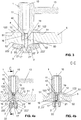
- Figure 1 shows a fastening device which is inserted into a mounting recess 50 of a toilet body 5 and has a fastening element 1 and an actuator element 4.
- the fastening element 1 comprises a bearing section 11, a stop section 12, a connecting section 16 and a pivot bearing section 17.
- the bearing section 11 is essentially designed as a round cylinder from which a bearing element 13 designed as a pin protrudes, on which a toilet cover (not shown), for example a toilet lid and / or a toilet seat, can be pivotably mounted.
- the stop section 12 is designed essentially as a flange which protrudes from the bearing section 11 and is wider than it.
- the stop section 12 is wider than the mounting recess 50, so that the stop surface 122 arranged on the underside of the stop section 12 can at least partially rest on the edge of the mounting recess 50.
- the part of the edge on which the stop surface 122 rests is referred to as the first assembly clamping surface 51.
- the connecting section 16 connects the stop section 12 to the pivot bearing section 17 and is designed to be sufficiently narrow that this, as in FIG Figure 1 shown, can preferably be arranged with a certain play in the mounting recess 50.
- the connecting section 16 is approximately as long as the mounting recess 50.
- Two identically shaped clamping elements 2, 2 ' are pivotably mounted on the pivot bearing section 17, in that pins 3, 3', each acting as a pivot axis, are guided through recesses 18 of the pivot bearing section 17 and through recesses 20, 20 'of the clamping elements 2, 2'.
- the clamping elements 2, 2 ' are each shown in a starting position in which the pivot bearing section 17 with the clamping elements 2, 2' can be inserted and removed from the assembly recess 50. In the starting position, the clamping elements 2, 2 ′ are arranged completely within the continuation of the cylinder of the bearing section 11.
- the clamping elements 2, 2 'each have a first arm section 21, 21' and a second arm section 22, 22 '.
- a pivoting clamping surface 222, 222 ' is arranged on each outer side of the second arm sections 22, 22', which in the FIGS Figure 1 Starting positions shown are approximately perpendicular to the stop surface 122 and approximately parallel to the cylinder axis.
- the respective first arm section 21, 21 ' is designed as a tab which, as in FIG Figure 4b can be seen, approximately half as wide as the second arm section 22, 22 '.
- the two tabs are interlaced, which enables a particularly compact design.
- a thread 19 is arranged, into which the actuator element 4 shown as a threaded pin is screwed.
- the threaded pin 4 has a driving profile 40, which can be accessed through a recess 10 in the fastening element 1, for example with a screwdriver.
- an end of the threaded pin 4 opposite the driving profile 40 rests against the two first arm sections 21, 21 'of the clamping elements 2, 2'.
- Figure 2 shows the fastening device in a transitional situation.
- the set screw 4 was - compared to the situation in Figure 1 - Screwed into the thread 19, so that the end of the threaded pin 4 opposite the driving profile 40 acts on the first arm sections 21, 21 'of the two clamping elements 2, 2'.
- the two clamping elements 2, 2 ' are pivoted. Since the respective pivot axis of the clamping elements 2, 2 'are arranged on different sides of the threaded pin 4, the two clamping elements 2, 2' are pivoted in two different directions.
- FIG. 3 shows the clamping elements 2, 2 'in a clamping position.
- the pivoting clamping surfaces 222, 222 ' are pressed from below against a second mounting clamping surface 52 arranged on the lower edge of the mounting recess 50, and the stop surface 122 is pressed by at the top against the first assembly clamping surface 51 arranged at the lower edge of the assembly recess 50 so that the toilet body 5 is clamped between the pivoting clamping surfaces 222, 222 'of the clamping elements 2, 2' and the stop surface 122, whereby the fastening device and in particular the fastening element 1 are attached to the toilet body 5.
- the pivoting clamping surfaces 222, 222 ′ are essentially parallel to the stop surface 122.
- the clamping elements 2, 2 ′ and the stop section 12 are preferably designed to be rigid, so that they are not deformed when clamped against the toilet body 5. These components are preferably made of metal or hard plastic.
- a rigid clamping element 2, 2 ' can enable stable clamping and / or reversible pivoting of the clamping elements 2, 2'.
- the Figure 4b shows a section through the CC plane in Figure 4a , whereby the position of the two clamping elements 2, 2 'in the starting position can be seen particularly well.
- the two clamping elements 2, 2 ' are interlocked in this position and the section runs both through the first arm section 21 of the first clamping element 2 and through the first arm section 21' of the second clamping element 2 '.
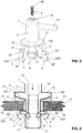
- FIG. 4 shows a three-dimensional exploded view of the fastening device from FIG Figures 1 - 4b .
- the bearing section 11 has a round cylinder from which the bearing element 13, which is also designed as a round cylinder, protrudes.
- the recess 10 in the fastening element 1, through which the actuator element 4 can be accessed, is also round.
- the stop section 12 is designed as a round flange and the stop surface 122 as a circumferential circular ring at its lower end.
- the recesses 18 in the pivot bearing section 17 and the recesses 20, 20 'in the clamping elements 2, 2', through which the pins 3, 3 'are pushed for pivotable mounting, can be clearly seen.
- Figure 6 shows another possible embodiment of the proposed fastening device.
- the stop section 12 is also fixedly arranged on the fastening element 1.
- the stop section 12 could, however, also be pivotable, for example Have clamping elements which press against the first assembly clamping surface 51 when actuated accordingly.
- the stop surface 122 is in the in Figure 6
- the example shown is not flat but curved.
- a correspondingly shaped support element 6 is arranged on the stop surface 122.
- the support element 6 can consist of a soft material such as rubber in order to be able to adapt if necessary and / or to protect the toilet body 5 when it is clamped.
- Soft support elements (not shown) could also be arranged on the pivoting clamping surfaces 222, 222 '.
Landscapes
- Engineering & Computer Science (AREA)
- General Engineering & Computer Science (AREA)
- Mechanical Engineering (AREA)
- Health & Medical Sciences (AREA)
- Public Health (AREA)
- Toilet Supplies (AREA)
- Bidet-Like Cleaning Device And Other Flush Toilet Accessories (AREA)
Abstract
Description
- Die vorliegende Erfindung betrifft Befestigungsvorrichten für Toilettenabdeckungen, wie beispielsweise Toilettendeckel oder Toilettenbrillen, an Toilettenkörpem nach dem Oberbegriff von Anspruch 1.
- Eine Toilettenabdeckung ist typischerweise schwenkbar an zwei Befestigungsvorrichtungen gelagert, welche wiederum an einen Toilettenkörper angeschraubt sind. Zur Montage oder Demontage einer Befestigungsvorrichtung ist zumeist Zugriff auf den Toilettenkörper von mehreren Seiten nötig, was oft umständlich und in manchen Konfigurationen gar nicht möglich ist.
- Aus
ES 1 136 030 U - Ausgehend von Stand der Technik liegt der Erfindung insbesondere die Aufgabe zugrunde, eine Befestigungsvorrichtung anzugeben, welche die Nachteile des Standes der Technik überwindet. Insbesondere solle eine Befestigungsvorrichtung angegeben werden, welche auf einfache Art montiert resp. demontiert werden können.
- Diese Aufgabe löst die Befestigungsvorrichtung, die Toiletten-Kombination, die Toilette und das Verfahren gemäss den unabhängigen Ansprüchen. Weitere Ausführungsformen sind in den abhängigen Ansprüchen angegeben.
- Eine vorgeschlagene Befestigungsvorrichtung zur Befestigung einer Toilettenabdeckung an einem Toilettenkörper umfasst ein Befestigungselement sowie ein Aktuatorelement. Das Befestigungselement umfasst einen Schwenklagerabschnitt, an welchem mindestens ein Klemmelement schwenkbar gelagert ist, wobei das mindestens ein Klemmelement durch eine Betätigung des Aktuatorelementes verschwenkbar ist. Das mindestens eine Klemmelement dient dazu, die Befestigungsvorrichtung an dem Toilettenkörper durch Klemmung zu befestigen. Die Befestigungsvorrichtung umfasst einen Anschlagsabschnitt mit einer Anschlagsfläche zur Auflage am Toilettenkörper, wobei der Toilettenkörper bevorzugt zwischen dem Klemmelement und den Anschlagsabschnitt eingeklemmt werden kann. Das Befestigungselement umfasst weiter einen Lagerabschnitt zur Lagerung der Toilettenabdeckung.
- Der Anschlagabschnitt ist vorzugsweise starr an dem Befestigungselement angeordnet, kann aber auch beweglich, beispielsweise als weiteres, im Abstand zum Schwenklagerabschnitt gelagertes Klemmelement, ausgebildet sein. Der Anschlagsabschnitt ist bevorzugt als Flansch und die Anschlagsfläche als ein Kreisring des Flansches ausgebildet.
- Vorzugsweise ist im eingeklemmten Zustand die Befestigungsvorrichtung kraftschlüssig aufgrund der Klemmwirkung mit dem Toilettenkörper verbunden. Eine formschlüssige Verbindung wäre auch denkbar.
- Das mindestens eine Klemmelement ist durch eine Betätigung des Aktuatorelementes vorzugsweise von einer Ausgangsposition in eine Klemmposition verschwenkbar, in welcher das Befestigungselement einen Toilettenkörper, bevorzugt zwischen dem Anschlagsabschnitt und dem mindestens einem Klemmelement, einklemmt.
- Vorzugsweise kann das mindestens eine Klemmelement, bevorzugt durch eine weitere Betätigung des Aktuatorelementes, von der Klemmposition in die Ausgangsposition verschwenkt werden kann. Dadurch kann die Befestigungsvorrichtung wieder in eine Ausgangssituation zurückversetzt werden und der Prozess in diesem Sinne reversibel sein. In der Ausgangsposition ist das mindestens eine Klemmelement bevorzugt in eine Montageaussparung des Toilettenkörpers ein- und ausführbar.
- Bevorzugt umfasst die Befestigungsvorrichtung, vorzugsweise der Lagerabschnitt, einen Zylinder, wobei das mindestens eine Klemmelement
- in der Ausgangsposition komplett innerhalb einer Fortsetzung des Zylinders angeordnet ist, und
- in der Klemmposition - zumindest teilweise - ausserhalb der Fortsetzung des Zylinders angeordnet ist.
- Die Breite des Zylinders ist vorzugsweise kleiner als die Breite eine Montageaussparung des Toilettenkörpers. Der Zylinder kann als runder oder allgemeiner Zylinder ausgebildet sein, dessen Grundfläche die Breite des Zylinders realisiert. Der Zylinder kann beispielsweise ein Gehäuse des Lagerabschnittes - zumindest teilweise - umranden. Der Zylinder ist vorzugsweise weniger breit als der Anschlagsabschnitt.
- Das mindestens eine Klemmelement umfasst vorzugsweise einen ersten Armabschnitt und einen zweiten Armabschnitt, welche bevorzugt so angeordnet sind, dass das Aktuatorelement bei Betätigung auf den ersten Armabschnitt wirkt und dadurch das Klemmelement verschwenkt. Vorzugsweise ist der zweite Armabschnitt dazu eingerichtet, in einer Klemmposition des Klemmelementes, bevorzugt mit einer an dem zweiten Armabschnitt angeordneten Schwenk-Klemmfläche, gegen den Toilettenkörper zu drücken. Vorzugsweise ist die Schwenk-Klemmfläche in der Klemmposition des Klemmelementes im Wesentlichen parallel zu der Anschlagsfläche. Eine winklige Ausrichtung, beispielsweise in einem Winkel von 0°±20° zur Anschlagsfläche wäre auch denkbar. In der Ausgangsposition ist die Schwenk-Klemmfläche bevorzugt im Wesentlichen senkrecht zur Anschlagsfläche. Eine winklige Ausrichtung, beispielsweise in einem Winkel von 90°±20° zur Anschlagsfläche wäre auch denkbar.
- An den Schwenk-Klemmflächen und/oder an der Anschlagfläche sind vorzugsweise weiche, insbesondere elastische, Auflageelemente, beispielsweise aus Gummi, angeordnet, welche bei Klemmung gegen den Toilettenkörper gepresst werden. Die weichen Auflageelemente können dazu geeignet sein,
- das Material des Toilettenkörpers und/oder der Befestigungsvorrichtung schützen; und/oder
- Unebenheiten, Schrägstellungen und/oder Fehlstellungen ausgleichen.
- Das mindestens eine Klemmelement ist vorzugsweise steif ausgebildet, so dass es sich im Normalgebrauch nicht verformt. Die Steifheit wird von der geometrischen Form und den verwendeten Materialien beeinflusst. Bevorzugt besteht das Klemmelement aus Metall.
- An dem Schwenklagerabschnitt sind vorzugsweise mindestens ein erstes Klemmelement und ein zweites Klemmelement schwenkbar gelagert. Durch die Anordnung von zwei Klemmelementen ergeht der Vorteil einer symmetrischen Abstützung.
- Die beiden Klemmelemente sind bevorzugt durch Betätigung eines einzigen Aktuatorelementes verschwenkbar. Das heisst, dass das Aktuatorelement auf beide Klemmelemente einwirkt.
- Die beiden Klemmelemente sind vorzugsweise so angeordnet, dass sie bei Betätigung in unterschiedliche Richtungen verschwenkt werden. Die beiden Schwenkebenen liegen vorzugsweise parallel zueinander oder in einem Winkel von 0°±20° zueinander. Bevorzugt sind die beiden Schwenkebenen identisch. Vorzugsweise verschwenken die beiden Klemmelemente in entgegengesetzte Richtungen, welche beispielsweise in einem Winkel von 180°±20° zueinander liegen.
- Vorzugsweise sind mindestens zwei Klemmelemente, zumindest in der jeweiligen Ausgangsposition, ineinander verschränkt. Dadurch kann eine besonders kompakte Bauweise ermöglicht werden. Die mindestens zwei Klemmelemente sind bevorzugt im Wesentlichen identisch geformt, und vorzugweise zueinander gedreht an dem Schwenklagerabschnitt angeordnet.
- In einigen Ausführungsbeispielen umfasst die Befestigungsvorrichtung genau zwei schwenkbar gelagerte Klemmelemente.
- Das Befestigungselement ist vorzugsweise als kompakte Einheit ausgebildet. Bevorzugt sind im Normalgebrauch alle Komponenten des Befestigungselementes fest miteinander verbunden und vorzugsweise so ausgebildet, dass die einzelnen Komponenten nicht voneinander trennbar sind. Bevorzugt sind die einzelnen Komponenten nicht ohne den Einsatz von Werkzeug voneinander trennbar. Beispielsweise kann das Befestigungselement, abgesehen von den Klemmelementen und den für deren Befestigung nötigen Komponenten, einstückig ausgebildet sein.
- Vorzugsweise sind verschwenkbaren Klemmelemente die einzigen beweglich gelagerten Komponenten des Befestigungselementes.
- Das Aktuatorelement ist vorzugsweise als Schraube, bevorzugt als Gewindestift ausgebildet. Das Befestigungselement umfasst vorzugsweise ein Gewinde, in welche die Schraube eingedreht werden kann. Die Befestigungsvorrichtung ist vorzugsweise so ausgebildet, dass durch Eindrehen der Schraube in das Gewinde das mindestens eine Klemmelement von einer Ausgangsposition in eine Klemmposition verschwenkt wird. Bevorzugt ist die Befestigungsvorrichtung ferner so ausgebildet, dass durch Ausdrehen der Aktuatorelement aus dem Gewinde, also Drehen in einer zum Eindrehen entgegengesetzten Richtung, das mindestens eine Klemmelement von der Klemmposition wieder in die Ausgangsposition verschwenkt wird. Das Aktuatorelement weist vorzugweise ein Mitnahmeprofil, beispielsweise einen Innenmehrkant, auf.
- Die Befestigungsvorrichtung ist vorzugsweise so ausgebildet, dass von der Seite aus, von der sie in den Toilettenkörper eingeführt werden kann, auch das Aktuatorelement betätigt werden kann. Dadurch können alle Schritte zur Montage der Befestigungsvorrichtung von einer Seite aus vorgenommen werden. Bevorzugt kann von dieser Seite auf ein Mitnahmeprofil des Aktuatorelementes zugegriffen werden.
- Vorzugsweise ist die Befestigungsvorrichtung so ausgebildet, dass ein Ende der Befestigungsvorrichtung, von dem aus das Aktuatorelement betätigt werden kann, einem Ende der Befestigungsvorrichtung, an dem der Schwenklagerabschnitt angeordnet ist, gegenüberliegt.
- Zudem wird eine Toiletten-Kombination aufweisend einen Toilettenkörper und eine hierin beschriebene Befestigungsvorrichtung vorgeschlagen. Der Toilettenkörper umfasst vorzugsweise eine Montageaussparung zur Einfuhr der Befestigungsvorrichtung zur Befestigung an dem Toilettenkörper. Die Toiletten-Kombination ist vorzugsweise so ausgebildet, dass das mindestens eine Klemmelement in einer Ausgangposition in die Montageaussparung, bevorzugt bis zum Anschlag des Anschlagabschnittes an einen Rand der Montageaussparung, eingeführt werden kann; und aus der Montageaussparung auch wieder ausgeführt werden kann. Die Toiletten-Kombination ist bevorzugt so ausgebildet, dass das mindestens eine Klemmelement in einer Klemmposition nicht aus der Montageaussparung ausgeführt werden kann. Die Toiletten-Kombination ist vorzugsweise so ausgebildet, dass die Befestigungsvorrichtung, wenn sie in die Montageaussparung eingeführt ist und das mindestens eine Klemmelement in eine Klemmposition verschwenkt ist, durch einen Klemmschluss, und bevorzugt auch durch einen Formschluss, mit dem Toilettenkörper verbunden ist.
- Der Anschlagsabschnitt und das mindestens eine Klemmelement sind vorzugsweise mit einem Abstand voneinander beabstandet, wobei der Abstand bevorzugt mindestens l°cm beträgt. Der Abstand entspricht vorzugsweise - zumindest im Wesentlichen - der Länge der Montageaussparung.
- Das Befestigungselement umfasst vorzugsweise einen den Anschlagabschnitt und den Schwenklagerabschnitt voneinander beabstandenden Verbindungsabschnitt, welcher bevorzugt im Wesentlichen so lang wie die Montageaussparung ist. Der Verbindungsabschnitt ist vorzugsweise nicht kürzer als die Montageaussparung. Die Länge des Verbindungsabschnittes entspricht bevorzugt im Wesentlichen dem besagten Abstand. Der Verbindungsabschnitt ist vorzugsweise dazu ausgebildet, im befestigten Zustand der Befestigungsvorrichtung in der Montageaussparung, angeordnet zu sein. Die Anschlagfläche ist bevorzugt auf der Höhe des Überganges des Anschlagabschnittes zum Verbindungsabschnitt angeordnet. Die Schwenk-Klemmfläche des mindestens einen Klemmelementes ist in Klemmposition vorzugsweise auf der Höhe des Überganges des Schwenklagerabschnittes zum Verbindungsabschnitt angeordnet.
- Die Toiletten-Kombination ist bevorzugt derart ausgebildet, dass
- der Anschlagsabschnitt, vorzugsweise die Anschlagsfläche, gegen eine, vorzugsweise an einem Rand der Montageaussparung angeordnete, erste Montageklemmfläche klemmen kann, und
- das mindestens eine Klemmelement, vorzugsweise die Schwenk-Klemmfläche, gegen eine, vorzugsweise an einem Rand der Montageaussparung angeordnete, zweite Montageklemmfläche klemmen kann.
- Die zweite Montageklemmfläche ist bevorzugt - zumindest im Wesentlichen - in eine zur der Richtung der ersten Montageklemmfläche entgegengesetzte Richtung angeordnet. Beispielswiese können die beiden Montageklemmflächen in einem Winkel von 180°+/-20° zueinander liegen. Vorzugsweise zeigt die obere Montageklemmfläche nach oben und die untere Montageklemmfläche nach unten.
- Es wird zudem eine Toilette umfassend eine hierin beschriebene Toiletten-Kombination sowie mindestens eine Toilettenabdeckung, vorzugsweise ein Toilettendeckel und/oder eine Toilettenbrille, vorgeschlagen, wobei die Toilettenabdeckung mittels der Befestigungsvorrichtung an dem Toilettenkörper befestigt ist.
- Zudem wird ein Verfahren zum Befestigen einer hierin beschriebenen Befestigungsvorrichtung an einem Toilettenkörper vorgestellt, welches die folgenden Schritte umfasst:
- Einführen, bevorzugt von oben, der Befestigungsvorrichtung in eine Montageaussparung des Toilettenkörpers durch Einführen des mindestens einen Klemmelementes in die Montageaussparung bis der Anschlagsabschnitt der Befestigungsvorrichtung an eine, vorzugsweise nach oben gerichtete, erste Montageklemmfläche der Montageaussparung anschlägt, und
- Betätigen des Aktuatorelementes, so dass das mindestens eine Klemmelement verschwenkt und gegen eine zweite, vorzugsweise nach unten gerichtete, Montageklemmfläche der Montageaussparung verklemmt.
- Bevorzugte Ausführungsformen der Erfindung werden im Folgenden anhand der Zeichnungen beschrieben, die lediglich zur Erläuterung dienen und nicht einschränkend auszulegen sind. In den Zeichnungen zeigen schematisch:
- Fig. 1
- eine in einen Toilettenkörper eingesetzte Befestigungsvorrichtung mit zwei Klemmelementen, welche sich in der Ausgangsposition befinden;
- Fig. 2
- die Befestigungsvorrichtung aus
Fig.1 , deren Klemmelemente sich in einem Übergangssituation von der Ausgangsposition in die Klemmposition befinden; - Fig. 3
- die Befestigungsvorrichtung aus
Fig.2 , deren Klemmelemente sich in der Klemmposition befinden; - Figs 4a/4b
- zwei Schnitte durch die in einen Toilettenkörper eingesetzte Befestigungsvorrichtung aus
Figur 1 ; - Fig. 5
- eine Explosionszeichnung einer Befestigungsvorrichtung aus den
Figuren 1-4b ; und - Fig. 6
- eine weitere in einen Toilettenkörper eingeklemmte Befestigungsvorrichtung.
-
Figur 1 zeigt eine in eine Montageaussparung 50 eines Toilettenkörpers 5 eingesetzte Befestigungsvorrichtung, welche ein Befestigungselement 1 sowie ein Aktuatorelement 4 aufweist. Das Befestigungselement 1 umfasst einen Lagerabschnitt 11, einen Anschlagsabschnitt 12, einen Verbindungsabschnitt 16 und einen Schwenklagerabschnitt 17. - Wie in
Figur 5 gut erkennbar ist, ist der Lagerabschnitt 11 im Wesentlichen als runder Zylinder ausgebildet, von dem ein als Zapfen ausgebildetes Lagerelement 13 absteht, an welchem eine Toilettenabdeckung (nicht gezeigt), beispielsweise ein Toilettendeckel und/oder eine Toilettenbrille, schwenkbar gelagert werden kann. - Der Anschlagsabschnitt 12 ist im Wesentlichen als Flansch ausgebildet, welcher von dem Lagerabschnitt 11 absteht und breiter als dieser ist. Der Anschlagsabschnitt 12 ist breiter als die Montageaussparung 50 ausgebildet, so dass die auf der Unterseite des Anschlagsabschnittes 12 angeordnete Anschlagfläche 122 auf dem Rand der Montageaussparung 50 zumindest teilweise aufliegen kann. Der Teil des Randes, auf dem die Anschlagfläche 122 aufliegt, wird als erste Montageklemmfläche 51 bezeichnet.
- Der Verbindungsabschnitt 16 verbindet den Anschlagsabschnitt 12 mit dem Schwenklagerabschnitt 17 und ist ausreichend schmal ausgebildet, dass dieser, wie in
Figur 1 dargestellt, vorzugsweise mit einem gewissen Spiel in der Montageaussparung 50 angeordnet werden kann. Der Verbindungsabschnitt 16 ist in etwa so lang wie die Montageaussparung 50. - An dem Schwenklagerabschnitt 17 sind zwei identisch geformte Klemmelemente 2, 2' schenkbar gelagert, indem jeweils als Schwenkachse fungierende Stifte 3, 3' durch Ausnehmungen 18 des Schwenklagerabschnittes 17 und durch Ausnehmungen 20, 20' der Klemmelemente 2, 2' geführt sind. In
Figur 1 sind die Klemmelemente 2, 2' jeweils in einer Ausgangsposition dargestellt, in welcher der Schwenklagerabschnitt 17 mit den Klemmelemente 2, 2' in die Montageaussparung 50 ein- und ausgeführt werden kann. Die Klemmelemente 2, 2' sind in der Ausgangsposition komplett innerhalb der Fortsetzung des Zylinders des Lagerabschnittes 11 angeordnet. Die Klemmelemente 2, 2' weisen jeweils einen ersten Armabschnitt 21, 21' sowie einen zweiten Armabschnitt 22, 22' auf. An aussen liegenden Seiten der zweiten Armabschnitte 22, 22' ist jeweils eine Schwenk-Klemmfläche 222, 222' angeordnet, welche in den inFigur 1 gezeigten Ausgangspositionen in etwa senkrecht zur Anschlagfläche 122 und in etwa parallel zur Zylinderachse liegen. Die beiden Klemmelemente 2, 2' sind zueinander um 180° gedreht angeordnet, so dass die beiden Schwenkebenen parallel zueinander liegen. Vorliegend sind die beiden Klemmelemente 2, 2' nebeneinander angeordnet, so dass die beiden - Schwenkebenen sogar identisch sind.
- Der jeweilige erste Armabschnitt 21, 21' ist als Lasche ausgebildet, welche, wie in
Figur 4b erkennbar ist, ungefähr halb so breit wie der zweite Armabschnitt 22, 22' ist. Durch die zueinander gedrehte und nur leicht versetzte Anordnung, sind die beiden Laschen ineinander verschränkt, wodurch eine besonders kompakte Ausgestaltung möglich ist. - In dem Befestigungselement 1 ist ein Gewinde 19 angeordnet, in welchem das als Gewindestift dargestellte Aktuatorelement 4 eingeschraubt ist. Der Gewindestift 4 weist ein Mitnahmeprofil 40 auf, auf welches durch eine Aussparung 10 in dem Befestigungselement 1, beispielsweise mit einem Schraubdreher, zugegriffen werden kann. In
Figur 1 liegt ein dem Mitnahmeprofil 40 gegenüberliegendes Ende des Gewindestiftes 4 an die beiden ersten Armabschnitte 21, 21' der Klemmelemente 2, 2' an. -
Figur 2 zeigt die Befestigungsvorrichtung in einer Übergangssituation. Der Gewindestift 4 wurde - im Verglich zur Situation inFigur 1 - in das Gewinde 19 eingedreht, so dass das dem Mitnahmeprofil 40 gegenüberliegende Ende des Gewindestiftes 4 auf die ersten Armabschnitte 21, 21' der beiden Klemmelemente 2, 2' wirkt. Durch diese Betätigung werden die beiden Klemmelemente 2, 2' verschwenkt. Da die jeweilige Schwenkachse der Klemmelemente 2, 2' auf unterschiedlichen Seiten des Gewindestiftes 4 angeordnet sind, werden die beiden Klemmelemente 2, 2' in zwei unterschiedliche Richtungen verschwenkt. In der inFigur 2 dargestellten Situation sind die beiden Klemmelemente 2, 2' bereits so stark verschenkt, dass sie, und insbesondere die beiden zweiten Armabschnitte 22, 22', die Fortsetzung des Zylinders des Lagerabschnittes 11 verlassen haben. In der inFigur 2 dargestellten Situation ist die Befestigungsvorrichtung durch die Anschlagsfläche 12 und die beiden Klemmelemente 2, 2' bereits mit dem Toilettenkörper 5 durch einen Formschluss verbunden. Insbesondere kann die Befestigungsvorrichtung nicht mehr nach oben ausgeführt werden, weil die Klemmelemente 2, 2' in ihrer dargestellten Position nicht mehr durch die Montageaussparung 50 passen. -
Figur 3 zeigt die Klemmelemente 2, 2' in einer Klemmposition. Dabei sind die Schwenk-Klemmflächen 222, 222' von unten gegen eine am unteren Rand der Montageaussparung 50 angeordnete zweite Montageklemmfläche 52 gedrückt und die Anschlagfläche 122 von oben gegen die am unteren Rand der Montageaussparung 50 angeordnete erste Montageklemmfläche 51 gedrückt, so dass der Toilettenkörper 5 zwischen den Schwenk-Klemmflächen 222, 222' der Klemmelemente 2, 2' und der Anschlagfläche 122 geklemmt ist, wodurch die Befestigungsvorrichtung und insbesondere das Befestigungselement 1 an dem Toilettenkörper 5 befestigt sind. In dieser Position liegen die Schwenk-Klemmflächen 222, 222' im Wesentlichen parallel zu der Anschlagfläche 122. - Die Klemmelemente 2, 2' und der Anschlagabschnitt 12 sind vorzugsweise steif ausgebildet, so dass sie beim Klemmen gegen den Toilettenkörper 5 nicht verformt werden. Bevorzugt bestehen diese Komponenten aus Metall oder Hartplastik. Ein steifes Klemmelement 2, 2' kann eine stabile Klemmung und/oder ein reversibles Verschwenken der Klemmelemente 2, 2' ermöglichen.
- Die
Figur 4b zeigt einen Schnitt durch die C-C-Ebene inFigur 4a , wodurch die Lage der beiden Klemmelemente 2, 2' in der Ausgangsposition besonders gut erkennbar ist. Die beiden Klemmelemente 2, 2' sind in dieser Position ineinander verschränkt und der Schnitt verläuft sowohl durch den ersten Armabschnitt 21 des ersten Klemmelementes 2, als auch durch den ersten Armabschnitt 21' des zweiten Klemmelementes 2'. -
Figur 5 zeigt eine dreidimensionale Explosionszeichnung der Befestigungsvorrichtung aus denFiguren 1 - 4b . Der Lagerabschnitt 11 weist einen runden Zylinder auf, aus dem das ebenfalls als runder Zylinder ausgebildete Lagerelement 13 herausragt. Auch die Aussparung 10 in dem Befestigungselement 1, durch welche auf das Aktuatorelement 4 zugegriffen werden kann, ist rund ausgebildet. Der Anschlagsabschnitt 12 ist als runder Flansch ausgebildet und die Anschlagfläche 122 als umlaufender Kreisring an dessen unterem Ende. Gut zu erkennen sind die Ausnehmungen 18 in dem Schwenklagerabschnitt 17 und die Ausnehmungen 20, 20' in den Klemmelementen 2, 2', durch welche zur schwenkbaren Lagerung die Stifte 3, 3' geschoben werden. -
Figur 6 zeigt eine andere mögliche Ausführungsform der vorgeschlagenen Befestigungsvorrichtung. Ebenso wie in dem in denFiguren 1-5 dargestellten Beispiel, ist auch hier der Anschlagsabschnitt 12 fest an dem Befestigungselement 1 angeordnet. Der Anschlagsabschnitt 12 könnte aber beispielsweise ebenfalls verschwenkbare Klemmelemente aufweisen, welche bei entsprechender Betätigung gegen die erste Montageklemmfläche 51 drücken. - Die Anschlagfläche 122 ist in dem in
Figur 6 gezeigten Beispiel nicht flach, sondern gebogen ausgebildet. Dafür ist an der Anschlagfläche 122 ein entsprechend geformtes Auflageelement 6 angeordnet. Das Auflageelement 6 kann aus einem weichen Material wie z.B. Gummi bestehen, um sich gegebenenfalls anpassen zu können und/oder den Toilettenkörper 5 bei der Klemmung zu schonen. Auch an den Schwenk-Klemmflächen 222, 222' könnten weiche Auflageelemente (nicht gezeigt) angeordnet sein. - Ebenso wie in dem in den
Figuren 1-5 dargestellten Beispiel, wirkt auch bei dem inFigur 6 gezeigten Beispiel das Aktuatorelement 4 bei Betätigung gleichermassen auf die beiden Klemmelemente 2, 2'. Es ist aber ebenso vorstellbar, dass das Aktuatorelement 4 zunächst nur auf eines der Klemmelemente wirkt, und dieses wiederum über eine Mechanik, z.B. über eine Verzahnung, auf das andere Klemmelement wirkt.BEZUGSZEICHENLISTE 1 Befestigungselement 21, 21' erster Armabschnitt 10 Aussparung 22, 22' zweiter Armabschnitt 11 Lagerabschnitt 222, 222' Schwenk-Klemmfläche 12 Anschlagsabschnitt 3, 3' Stifte 122 Anschlagfläche 4 Aktuatorelement 13 Lagerelement (Zapfen) 40 Mitnahmeprofil 16 Verbindungsabschnitt 5 Toilettenkörper 17 Schwenklagerabschnitt 50 Montageaussparung 18 Ausnehmung 51 erste Montageklemmfläche 19 Gewinde 52 zweite Montageklemmfläche 2, 2' Klemmelement 6 Auflageelement 20, 20' Ausnehmung
Claims (16)
- Befestigungsvorrichtung zur Befestigung einer Toilettenabdeckung an einem Toilettenkörper (5), umfassendein Befestigungselement (1) mit einem Anschlagsabschnitt (12) mit einer Anschlagsfläche (122) zur Auflage am Toilettenkörper (5) und einem Lagerabschnitt (11) zur Lagerung der Toilettenabdeckung, undein Aktuatorelement (4),dadurch gekennzeichnet, dass das Befestigungselement (1) weiter einen Schwenklagerabschnitt (17) umfasst, an welchem mindestens ein Klemmelement (2) schwenkbar gelagert ist und dass das mindestens eine Klemmelement (2) durch eine Betätigung des Aktuatorelementes (4) verschwenkbar ist.
- Befestigungsvorrichtung gemäss Anspruch 1, dadurch gekennzeichnet, dass das mindestens eine Klemmelement (2) durch eine Betätigung des Aktuatorelementes (4) von einer Ausgangsposition in eine Klemmposition verschwenkbar ist, in welcher zwischen dem Anschlagsabschnitt (12) und dem mindestens einem Klemmelement (2) ein Toilettenkörper (5) einklemmt werden kann und dadurch das Befestigungselement (1) an dem Toilettenkörper (5) befestigt werden kann.
- Befestigungsvorrichtung gemäss Anspruch 2, dadurch gekennzeichnet, dass der Lagerabschnitt (11) einen Zylinder aufweist und das mindestens eine Klemmelement (2) in der Ausgangsposition komplett innerhalb einer Fortsetzung des Zylinders liegt, und in der Klemmposition ausserhalb der Fortsetzung des Zylinders liegt.
- Befestigungsvorrichtung gemäss einem der Ansprüche 2 oder 3, dadurch gekennzeichnet, dass das mindestens eine Klemmelement (2) durch die Betätigung des Aktuatorelementes (4) von der Klemmposition in die Ausgangsposition verschwenkt werden kann.
- Befestigungsvorrichtung gemäss einem der vorstehenden Ansprüche, dadurch gekennzeichnet, dass das mindestens eine Klemmelement (2) einen ersten Armabschnitt (21) und einen zweiten Armabschnitt (22) umfasst, welche so angeordnet sind, dass das Aktuatorelement (4) bei Betätigung auf den ersten Armabschnitt (21) wirkt und dadurch das Klemmelement (2) verschwenkt.
- Befestigungsvorrichtung gemäss einem der vorstehenden Ansprüche, dadurch gekennzeichnet, dass das mindestens eine Klemmelement (2) steif ausgebildet ist, wobei das Klemmelement vorzugsweise im Wesentlichen aus Metall besteht.
- Befestigungsvorrichtung gemäss einem der vorstehenden Ansprüche, dadurch gekennzeichnet, dass an dem Schwenklagerabschnitt (17) ein erstes Klemmelement (2) und ein zweites Klemmelement (2') schwenkbar gelagert sind.
- Befestigungsvorrichtung gemäss Anspruch 7, dadurch gekennzeichnet, dass beide Klemmelemente (2, 2') durch Betätigung eines einzigen Aktuatorelementes (4) verschwenkbar sind.
- Befestigungsvorrichtung gemäss einem der Ansprüche 7 oder 8, dadurch gekennzeichnet, dass die beiden Klemmelemente (2, 2') so angeordnet sind, dass sie bei Betätigung in unterschiedliche Richtungen, vorzugsweise entgegengesetzte Richtungen, verschwenkt werden.
- Befestigungsvorrichtung gemäss Anspruch 7 bis 9, dadurch gekennzeichnet, dass beide Klemmelemente (2, 2'), zumindest in einer jeweiligen Ausgangsposition, ineinander verschränkt sind.
- Befestigungsvorrichtung gemäss einem der vorstehenden Ansprüche, dadurch gekennzeichnet, dass das Klemmelement (2) bzw. die Klemmelemente (2, 2') die einzigen beweglich gelagerten Komponenten des Befestigungselementes (1) sind.
- Befestigungsvorrichtung gemäss einem der vorstehenden Ansprüche, dadurch gekennzeichnet, dass das Aktuatorelement (4) als Schraube, vorzugsweise als Gewindestift, ausgebildet, ist.
- Toiletten-Kombination umfassend eine Befestigungsvorrichtung gemäss einem der vorstehenden Ansprüche und einen Toilettenkörper (5), wobei der Toilettenkörper (5) eine Montageaussparung (50) zur Einfuhr der Befestigungsvorrichtung zur Befestigung an dem Toilettenkörper (5) umfasst, und dass die Toiletten-Kombination vorzugsweise so ausgebildet ist,- dass das mindestens eine Klemmelement (2) in einer Ausgangposition in die Montageaussparung (50) eingeführt und aus der Montageaussparung (50) ausgeführt werden kann, und- dass die Befestigungsvorrichtung, wenn sie in die Montageaussparung (50) eingeführt ist und das mindestens eine Klemmelement (2) in eine Klemmposition verschwenkt ist, durch einen Klemmschluss, und vorzugsweise auch durch einen Formschluss, mit dem Toilettenkörper (5) verbunden ist.
- Toiletten-Kombination gemäss Anspruch 13, dadurch gekennzeichnet, dass das Befestigungselement (1) einen den Anschlagabschnitt (11) und den Schwenklagerabschnitt (17) voneinander beabstandenden Verbindungsabschnitt (16) umfasst, welcher im Wesentlichen so lang wie die Montageaussparung (50) ist.
- Toilette umfassend eine Toiletten-Kombination gemäss einem der Ansprüche 13 oder 14 und mindestens eine Toilettenabdeckung, wobei die Toilettenabdeckung mittels der Befestigungsvorrichtung an dem Toilettenkörper (5) befestigt ist.
- Verfahren zum Befestigen einer Befestigungsvorrichtung gemäss einem der Ansprüche 1 bis 12 an einem Toilettenkörper (5), umfassend- Einführen der Befestigungsvorrichtung in eine Montageaussparung (50) des Toilettenkörpers (5) durch Einführen des mindestens einen Klemmelementes (2) in die Montageaussparung (50) bis der Anschlagsabschnitt (12) der Befestigungsvorrichtung an eine erste Montageklemmfläche (51) der Montageaussparung (50) anschlägt, und- Betätigen des Aktuatorelementes (4), so dass das mindestens eine Klemmelement (2) verschwenkt und gegen eine zweite Montageklemmfläche (52) der Montageaussparung (50) verklemmt.
Priority Applications (2)
| Application Number | Priority Date | Filing Date | Title |
|---|---|---|---|
| EP19176402.6A EP3741274B1 (de) | 2019-05-24 | 2019-05-24 | Befestigungsvorrichtung für toilettenabdeckungen |
| CH01624/19A CH716133B1 (de) | 2019-05-24 | 2019-12-13 | Befestigungsvorrichtung für Toilettenabdeckungen. |
Applications Claiming Priority (1)
| Application Number | Priority Date | Filing Date | Title |
|---|---|---|---|
| EP19176402.6A EP3741274B1 (de) | 2019-05-24 | 2019-05-24 | Befestigungsvorrichtung für toilettenabdeckungen |
Publications (2)
| Publication Number | Publication Date |
|---|---|
| EP3741274A1 true EP3741274A1 (de) | 2020-11-25 |
| EP3741274B1 EP3741274B1 (de) | 2023-07-19 |
Family
ID=66647233
Family Applications (1)
| Application Number | Title | Priority Date | Filing Date |
|---|---|---|---|
| EP19176402.6A Active EP3741274B1 (de) | 2019-05-24 | 2019-05-24 | Befestigungsvorrichtung für toilettenabdeckungen |
Country Status (2)
| Country | Link |
|---|---|
| EP (1) | EP3741274B1 (de) |
| CH (1) | CH716133B1 (de) |
Citations (4)
| Publication number | Priority date | Publication date | Assignee | Title |
|---|---|---|---|---|
| US20070017013A1 (en) * | 2005-07-20 | 2007-01-25 | Clarifia | Toilet seat hinge |
| GB2475070A (en) * | 2009-11-04 | 2011-05-11 | Practitioners Ltd | Toggle fixing device |
| ES1136030U (es) | 2014-12-31 | 2015-02-12 | Roca Sanitario, S. A. | Taco para fijar una tapa y asiento a un inodoro |
| GB2566357A (en) * | 2017-07-11 | 2019-03-13 | Cassellie Ltd | Engagement apparatus and method of use thereof |
Family Cites Families (1)
| Publication number | Priority date | Publication date | Assignee | Title |
|---|---|---|---|---|
| WO2014109721A1 (en) * | 2013-01-11 | 2014-07-17 | Eczacibaşi Yapi Gereçleri Sanayi Ve Ticaret Anonim Şirketi | A fastening system developed for installation of the toilet seat & covers and hinge systems used in the toilet seat & covers to the sanitaryware product surfaces |
-
2019
- 2019-05-24 EP EP19176402.6A patent/EP3741274B1/de active Active
- 2019-12-13 CH CH01624/19A patent/CH716133B1/de not_active IP Right Cessation
Patent Citations (4)
| Publication number | Priority date | Publication date | Assignee | Title |
|---|---|---|---|---|
| US20070017013A1 (en) * | 2005-07-20 | 2007-01-25 | Clarifia | Toilet seat hinge |
| GB2475070A (en) * | 2009-11-04 | 2011-05-11 | Practitioners Ltd | Toggle fixing device |
| ES1136030U (es) | 2014-12-31 | 2015-02-12 | Roca Sanitario, S. A. | Taco para fijar una tapa y asiento a un inodoro |
| GB2566357A (en) * | 2017-07-11 | 2019-03-13 | Cassellie Ltd | Engagement apparatus and method of use thereof |
Also Published As
| Publication number | Publication date |
|---|---|
| EP3741274B1 (de) | 2023-07-19 |
| CH716133B1 (de) | 2020-11-13 |
Similar Documents
| Publication | Publication Date | Title |
|---|---|---|
| EP0445591B1 (de) | Einrichtung zum Verbinden einer Lenksäule eines Kraftfahrzeuges mit einem Wellenzapfen eines Lenkgetriebes | |
| EP3303851B1 (de) | Vorrichtung zum halten eines bauteils | |
| EP3741275B1 (de) | Kippdübel | |
| DE102013113735A1 (de) | Befestiger, Befestigungssystem und Verfahren zur Montage eines Befestigers an einer Montageschiene | |
| DE3930327A1 (de) | Spannschlossmutter-befestigungsvorrichtung | |
| DE202018103239U1 (de) | Druckeinstellvorrichtung für Schnellspanner | |
| EP3132146A1 (de) | Befestigungsvorrichtung | |
| EP1269564B1 (de) | Vorrichtung zur befestigung einer fahrzeugantenne | |
| EP2792830B1 (de) | Beschlagteil mit halteelement zur halterung des beschlagteils | |
| DE102022134745A1 (de) | Befestigungsanordnung mit toleranzausgleich | |
| DE102019206750B4 (de) | Vorrichtung zum Ausgleichen von Toleranzen zwischen einem ersten Bauteil und einem zweiten Bauteil | |
| EP3741274B1 (de) | Befestigungsvorrichtung für toilettenabdeckungen | |
| EP3695748B1 (de) | Einbauschrankanordnung | |
| WO2008012074A1 (de) | Sicherungsmutter | |
| EP4067586A1 (de) | Wandhalterung | |
| EP3819645A1 (de) | Versteifungselement zum versteifen eines testkontaktorsystems, verwendung und verfahren zur montage eines testkontaktorsystems | |
| EP0615073B1 (de) | Kombination aus Schraubenmutter und Lochscheibe | |
| EP4274093A2 (de) | Montagesystem für photovoltaikmodule und bestandteile eines montagesystems für photovoltaikmodule zur verbesserung der installation | |
| DE10102862A1 (de) | Klemmhalterung bestehend aus einem Basisteil und einem dazugehörigen Deckelteil | |
| DE29603389U1 (de) | Schnellverschluß | |
| DE102017009402B4 (de) | Befestigungsvorrichtung | |
| EP1582802A1 (de) | Halterungsvorrichtung für einen Flachbildschirm | |
| DE102019134582A1 (de) | Bolzenaufnahme sowie ein Verfahren zum Anordnen von Rastarmen einer Bolzenaufnahme | |
| DE29804519U1 (de) | Vorrichtung zur Verbindung eines Sitzes und eines Deckels mit einer Toilettenschlüssel | |
| DE102018203080A1 (de) | Fundamentsystem für die lagerung von flächig nebeneinander angeordneten solarpaneelen |
Legal Events
| Date | Code | Title | Description |
|---|---|---|---|
| PUAI | Public reference made under article 153(3) epc to a published international application that has entered the european phase |
Free format text: ORIGINAL CODE: 0009012 |
|
| STAA | Information on the status of an ep patent application or granted ep patent |
Free format text: STATUS: THE APPLICATION HAS BEEN PUBLISHED |
|
| AK | Designated contracting states |
Kind code of ref document: A1 Designated state(s): AL AT BE BG CH CY CZ DE DK EE ES FI FR GB GR HR HU IE IS IT LI LT LU LV MC MK MT NL NO PL PT RO RS SE SI SK SM TR |
|
| AX | Request for extension of the european patent |
Extension state: BA ME |
|
| STAA | Information on the status of an ep patent application or granted ep patent |
Free format text: STATUS: REQUEST FOR EXAMINATION WAS MADE |
|
| 17P | Request for examination filed |
Effective date: 20210325 |
|
| RBV | Designated contracting states (corrected) |
Designated state(s): AL AT BE BG CH CY CZ DE DK EE ES FI FR GB GR HR HU IE IS IT LI LT LU LV MC MK MT NL NO PL PT RO RS SE SI SK SM TR |
|
| GRAP | Despatch of communication of intention to grant a patent |
Free format text: ORIGINAL CODE: EPIDOSNIGR1 |
|
| STAA | Information on the status of an ep patent application or granted ep patent |
Free format text: STATUS: GRANT OF PATENT IS INTENDED |
|
| INTG | Intention to grant announced |
Effective date: 20230222 |
|
| GRAS | Grant fee paid |
Free format text: ORIGINAL CODE: EPIDOSNIGR3 |
|
| GRAA | (expected) grant |
Free format text: ORIGINAL CODE: 0009210 |
|
| STAA | Information on the status of an ep patent application or granted ep patent |
Free format text: STATUS: THE PATENT HAS BEEN GRANTED |
|
| AK | Designated contracting states |
Kind code of ref document: B1 Designated state(s): AL AT BE BG CH CY CZ DE DK EE ES FI FR GB GR HR HU IE IS IT LI LT LU LV MC MK MT NL NO PL PT RO RS SE SI SK SM TR |
|
| REG | Reference to a national code |
Ref country code: GB Ref legal event code: FG4D Free format text: NOT ENGLISH |
|
| REG | Reference to a national code |
Ref country code: CH Ref legal event code: EP |
|
| REG | Reference to a national code |
Ref country code: DE Ref legal event code: R096 Ref document number: 502019008566 Country of ref document: DE |
|
| P01 | Opt-out of the competence of the unified patent court (upc) registered |
Effective date: 20230629 |
|
| REG | Reference to a national code |
Ref country code: IE Ref legal event code: FG4D Free format text: LANGUAGE OF EP DOCUMENT: GERMAN |
|
| REG | Reference to a national code |
Ref country code: LT Ref legal event code: MG9D |
|
| REG | Reference to a national code |
Ref country code: NL Ref legal event code: MP Effective date: 20230719 |
|
| PG25 | Lapsed in a contracting state [announced via postgrant information from national office to epo] |
Ref country code: NL Free format text: LAPSE BECAUSE OF FAILURE TO SUBMIT A TRANSLATION OF THE DESCRIPTION OR TO PAY THE FEE WITHIN THE PRESCRIBED TIME-LIMIT Effective date: 20230719 |
|
| PG25 | Lapsed in a contracting state [announced via postgrant information from national office to epo] |
Ref country code: GR Free format text: LAPSE BECAUSE OF FAILURE TO SUBMIT A TRANSLATION OF THE DESCRIPTION OR TO PAY THE FEE WITHIN THE PRESCRIBED TIME-LIMIT Effective date: 20231020 |
|
| PG25 | Lapsed in a contracting state [announced via postgrant information from national office to epo] |
Ref country code: IS Free format text: LAPSE BECAUSE OF FAILURE TO SUBMIT A TRANSLATION OF THE DESCRIPTION OR TO PAY THE FEE WITHIN THE PRESCRIBED TIME-LIMIT Effective date: 20231119 |
|
| PG25 | Lapsed in a contracting state [announced via postgrant information from national office to epo] |
Ref country code: SE Free format text: LAPSE BECAUSE OF FAILURE TO SUBMIT A TRANSLATION OF THE DESCRIPTION OR TO PAY THE FEE WITHIN THE PRESCRIBED TIME-LIMIT Effective date: 20230719 Ref country code: RS Free format text: LAPSE BECAUSE OF FAILURE TO SUBMIT A TRANSLATION OF THE DESCRIPTION OR TO PAY THE FEE WITHIN THE PRESCRIBED TIME-LIMIT Effective date: 20230719 Ref country code: PT Free format text: LAPSE BECAUSE OF FAILURE TO SUBMIT A TRANSLATION OF THE DESCRIPTION OR TO PAY THE FEE WITHIN THE PRESCRIBED TIME-LIMIT Effective date: 20231120 Ref country code: NO Free format text: LAPSE BECAUSE OF FAILURE TO SUBMIT A TRANSLATION OF THE DESCRIPTION OR TO PAY THE FEE WITHIN THE PRESCRIBED TIME-LIMIT Effective date: 20231019 Ref country code: LV Free format text: LAPSE BECAUSE OF FAILURE TO SUBMIT A TRANSLATION OF THE DESCRIPTION OR TO PAY THE FEE WITHIN THE PRESCRIBED TIME-LIMIT Effective date: 20230719 Ref country code: LT Free format text: LAPSE BECAUSE OF FAILURE TO SUBMIT A TRANSLATION OF THE DESCRIPTION OR TO PAY THE FEE WITHIN THE PRESCRIBED TIME-LIMIT Effective date: 20230719 Ref country code: IS Free format text: LAPSE BECAUSE OF FAILURE TO SUBMIT A TRANSLATION OF THE DESCRIPTION OR TO PAY THE FEE WITHIN THE PRESCRIBED TIME-LIMIT Effective date: 20231119 Ref country code: HR Free format text: LAPSE BECAUSE OF FAILURE TO SUBMIT A TRANSLATION OF THE DESCRIPTION OR TO PAY THE FEE WITHIN THE PRESCRIBED TIME-LIMIT Effective date: 20230719 Ref country code: GR Free format text: LAPSE BECAUSE OF FAILURE TO SUBMIT A TRANSLATION OF THE DESCRIPTION OR TO PAY THE FEE WITHIN THE PRESCRIBED TIME-LIMIT Effective date: 20231020 Ref country code: FI Free format text: LAPSE BECAUSE OF FAILURE TO SUBMIT A TRANSLATION OF THE DESCRIPTION OR TO PAY THE FEE WITHIN THE PRESCRIBED TIME-LIMIT Effective date: 20230719 |
|
| PG25 | Lapsed in a contracting state [announced via postgrant information from national office to epo] |
Ref country code: PL Free format text: LAPSE BECAUSE OF FAILURE TO SUBMIT A TRANSLATION OF THE DESCRIPTION OR TO PAY THE FEE WITHIN THE PRESCRIBED TIME-LIMIT Effective date: 20230719 |
|
| REG | Reference to a national code |
Ref country code: DE Ref legal event code: R097 Ref document number: 502019008566 Country of ref document: DE |
|
| PG25 | Lapsed in a contracting state [announced via postgrant information from national office to epo] |
Ref country code: ES Free format text: LAPSE BECAUSE OF FAILURE TO SUBMIT A TRANSLATION OF THE DESCRIPTION OR TO PAY THE FEE WITHIN THE PRESCRIBED TIME-LIMIT Effective date: 20230719 |
|
| PG25 | Lapsed in a contracting state [announced via postgrant information from national office to epo] |
Ref country code: SM Free format text: LAPSE BECAUSE OF FAILURE TO SUBMIT A TRANSLATION OF THE DESCRIPTION OR TO PAY THE FEE WITHIN THE PRESCRIBED TIME-LIMIT Effective date: 20230719 Ref country code: RO Free format text: LAPSE BECAUSE OF FAILURE TO SUBMIT A TRANSLATION OF THE DESCRIPTION OR TO PAY THE FEE WITHIN THE PRESCRIBED TIME-LIMIT Effective date: 20230719 Ref country code: ES Free format text: LAPSE BECAUSE OF FAILURE TO SUBMIT A TRANSLATION OF THE DESCRIPTION OR TO PAY THE FEE WITHIN THE PRESCRIBED TIME-LIMIT Effective date: 20230719 Ref country code: EE Free format text: LAPSE BECAUSE OF FAILURE TO SUBMIT A TRANSLATION OF THE DESCRIPTION OR TO PAY THE FEE WITHIN THE PRESCRIBED TIME-LIMIT Effective date: 20230719 Ref country code: DK Free format text: LAPSE BECAUSE OF FAILURE TO SUBMIT A TRANSLATION OF THE DESCRIPTION OR TO PAY THE FEE WITHIN THE PRESCRIBED TIME-LIMIT Effective date: 20230719 Ref country code: CZ Free format text: LAPSE BECAUSE OF FAILURE TO SUBMIT A TRANSLATION OF THE DESCRIPTION OR TO PAY THE FEE WITHIN THE PRESCRIBED TIME-LIMIT Effective date: 20230719 Ref country code: SK Free format text: LAPSE BECAUSE OF FAILURE TO SUBMIT A TRANSLATION OF THE DESCRIPTION OR TO PAY THE FEE WITHIN THE PRESCRIBED TIME-LIMIT Effective date: 20230719 |
|
| PLBE | No opposition filed within time limit |
Free format text: ORIGINAL CODE: 0009261 |
|
| STAA | Information on the status of an ep patent application or granted ep patent |
Free format text: STATUS: NO OPPOSITION FILED WITHIN TIME LIMIT |
|
| PG25 | Lapsed in a contracting state [announced via postgrant information from national office to epo] |
Ref country code: IT Free format text: LAPSE BECAUSE OF FAILURE TO SUBMIT A TRANSLATION OF THE DESCRIPTION OR TO PAY THE FEE WITHIN THE PRESCRIBED TIME-LIMIT Effective date: 20230719 |
|
| 26N | No opposition filed |
Effective date: 20240422 |
|
| PG25 | Lapsed in a contracting state [announced via postgrant information from national office to epo] |
Ref country code: SI Free format text: LAPSE BECAUSE OF FAILURE TO SUBMIT A TRANSLATION OF THE DESCRIPTION OR TO PAY THE FEE WITHIN THE PRESCRIBED TIME-LIMIT Effective date: 20230719 |
|
| PG25 | Lapsed in a contracting state [announced via postgrant information from national office to epo] |
Ref country code: BG Free format text: LAPSE BECAUSE OF FAILURE TO SUBMIT A TRANSLATION OF THE DESCRIPTION OR TO PAY THE FEE WITHIN THE PRESCRIBED TIME-LIMIT Effective date: 20230719 |
|
| PG25 | Lapsed in a contracting state [announced via postgrant information from national office to epo] |
Ref country code: BG Free format text: LAPSE BECAUSE OF FAILURE TO SUBMIT A TRANSLATION OF THE DESCRIPTION OR TO PAY THE FEE WITHIN THE PRESCRIBED TIME-LIMIT Effective date: 20230719 |
|
| PG25 | Lapsed in a contracting state [announced via postgrant information from national office to epo] |
Ref country code: MC Free format text: LAPSE BECAUSE OF FAILURE TO SUBMIT A TRANSLATION OF THE DESCRIPTION OR TO PAY THE FEE WITHIN THE PRESCRIBED TIME-LIMIT Effective date: 20230719 |
|
| REG | Reference to a national code |
Ref country code: AT Ref legal event code: PC Ref document number: 1588587 Country of ref document: AT Kind code of ref document: T Owner name: GEBERIT INTERNATIONAL AG, CH Effective date: 20241118 |
|
| PG25 | Lapsed in a contracting state [announced via postgrant information from national office to epo] |
Ref country code: LU Free format text: LAPSE BECAUSE OF NON-PAYMENT OF DUE FEES Effective date: 20240524 |
|
| GBPC | Gb: european patent ceased through non-payment of renewal fee |
Effective date: 20240524 |
|
| PG25 | Lapsed in a contracting state [announced via postgrant information from national office to epo] |
Ref country code: MC Free format text: LAPSE BECAUSE OF FAILURE TO SUBMIT A TRANSLATION OF THE DESCRIPTION OR TO PAY THE FEE WITHIN THE PRESCRIBED TIME-LIMIT Effective date: 20230719 Ref country code: LU Free format text: LAPSE BECAUSE OF NON-PAYMENT OF DUE FEES Effective date: 20240524 |
|
| REG | Reference to a national code |
Ref country code: BE Ref legal event code: MM Effective date: 20240531 |
|
| PG25 | Lapsed in a contracting state [announced via postgrant information from national office to epo] |
Ref country code: IE Free format text: LAPSE BECAUSE OF NON-PAYMENT OF DUE FEES Effective date: 20240524 |
|
| PG25 | Lapsed in a contracting state [announced via postgrant information from national office to epo] |
Ref country code: BE Free format text: LAPSE BECAUSE OF NON-PAYMENT OF DUE FEES Effective date: 20240531 |
|
| PG25 | Lapsed in a contracting state [announced via postgrant information from national office to epo] |
Ref country code: FR Free format text: LAPSE BECAUSE OF NON-PAYMENT OF DUE FEES Effective date: 20240531 |
|
| PG25 | Lapsed in a contracting state [announced via postgrant information from national office to epo] |
Ref country code: GB Free format text: LAPSE BECAUSE OF NON-PAYMENT OF DUE FEES Effective date: 20240524 |
|
| PGFP | Annual fee paid to national office [announced via postgrant information from national office to epo] |
Ref country code: DE Payment date: 20250521 Year of fee payment: 7 |
|
| PGFP | Annual fee paid to national office [announced via postgrant information from national office to epo] |
Ref country code: CH Payment date: 20250601 Year of fee payment: 7 |
|
| PGFP | Annual fee paid to national office [announced via postgrant information from national office to epo] |
Ref country code: AT Payment date: 20250522 Year of fee payment: 7 |
|
| PG25 | Lapsed in a contracting state [announced via postgrant information from national office to epo] |
Ref country code: CY Free format text: LAPSE BECAUSE OF FAILURE TO SUBMIT A TRANSLATION OF THE DESCRIPTION OR TO PAY THE FEE WITHIN THE PRESCRIBED TIME-LIMIT; INVALID AB INITIO Effective date: 20190524 |
|
| PG25 | Lapsed in a contracting state [announced via postgrant information from national office to epo] |
Ref country code: HU Free format text: LAPSE BECAUSE OF FAILURE TO SUBMIT A TRANSLATION OF THE DESCRIPTION OR TO PAY THE FEE WITHIN THE PRESCRIBED TIME-LIMIT; INVALID AB INITIO Effective date: 20190524 |