EP3740940B1 - Système de badge d'identification - Google Patents
Système de badge d'identification Download PDFInfo
- Publication number
- EP3740940B1 EP3740940B1 EP18804780.7A EP18804780A EP3740940B1 EP 3740940 B1 EP3740940 B1 EP 3740940B1 EP 18804780 A EP18804780 A EP 18804780A EP 3740940 B1 EP3740940 B1 EP 3740940B1
- Authority
- EP
- European Patent Office
- Prior art keywords
- badge
- base station
- reusable
- identification
- information
- Prior art date
- Legal status (The legal status is an assumption and is not a legal conclusion. Google has not performed a legal analysis and makes no representation as to the accuracy of the status listed.)
- Active
Links
Images

Classifications
-
- G—PHYSICS
- G07—CHECKING-DEVICES
- G07C—TIME OR ATTENDANCE REGISTERS; REGISTERING OR INDICATING THE WORKING OF MACHINES; GENERATING RANDOM NUMBERS; VOTING OR LOTTERY APPARATUS; ARRANGEMENTS, SYSTEMS OR APPARATUS FOR CHECKING NOT PROVIDED FOR ELSEWHERE
- G07C9/00—Individual registration on entry or exit
- G07C9/20—Individual registration on entry or exit involving the use of a pass
- G07C9/21—Individual registration on entry or exit involving the use of a pass having a variable access code
-
- G—PHYSICS
- G07—CHECKING-DEVICES
- G07C—TIME OR ATTENDANCE REGISTERS; REGISTERING OR INDICATING THE WORKING OF MACHINES; GENERATING RANDOM NUMBERS; VOTING OR LOTTERY APPARATUS; ARRANGEMENTS, SYSTEMS OR APPARATUS FOR CHECKING NOT PROVIDED FOR ELSEWHERE
- G07C9/00—Individual registration on entry or exit
- G07C9/20—Individual registration on entry or exit involving the use of a pass
- G07C9/28—Individual registration on entry or exit involving the use of a pass the pass enabling tracking or indicating presence
-
- G—PHYSICS
- G06—COMPUTING OR CALCULATING; COUNTING
- G06F—ELECTRIC DIGITAL DATA PROCESSING
- G06F3/00—Input arrangements for transferring data to be processed into a form capable of being handled by the computer; Output arrangements for transferring data from processing unit to output unit, e.g. interface arrangements
- G06F3/14—Digital output to display device ; Cooperation and interconnection of the display device with other functional units
- G06F3/147—Digital output to display device ; Cooperation and interconnection of the display device with other functional units using display panels
-
- G—PHYSICS
- G06—COMPUTING OR CALCULATING; COUNTING
- G06K—GRAPHICAL DATA READING; PRESENTATION OF DATA; RECORD CARRIERS; HANDLING RECORD CARRIERS
- G06K19/00—Record carriers for use with machines and with at least a part designed to carry digital markings
- G06K19/06—Record carriers for use with machines and with at least a part designed to carry digital markings characterised by the kind of the digital marking, e.g. shape, nature, code
- G06K19/06009—Record carriers for use with machines and with at least a part designed to carry digital markings characterised by the kind of the digital marking, e.g. shape, nature, code with optically detectable marking
- G06K19/06018—Record carriers for use with machines and with at least a part designed to carry digital markings characterised by the kind of the digital marking, e.g. shape, nature, code with optically detectable marking one-dimensional coding
- G06K19/06028—Record carriers for use with machines and with at least a part designed to carry digital markings characterised by the kind of the digital marking, e.g. shape, nature, code with optically detectable marking one-dimensional coding using bar codes
-
- G—PHYSICS
- G06—COMPUTING OR CALCULATING; COUNTING
- G06K—GRAPHICAL DATA READING; PRESENTATION OF DATA; RECORD CARRIERS; HANDLING RECORD CARRIERS
- G06K19/00—Record carriers for use with machines and with at least a part designed to carry digital markings
- G06K19/06—Record carriers for use with machines and with at least a part designed to carry digital markings characterised by the kind of the digital marking, e.g. shape, nature, code
- G06K19/067—Record carriers with conductive marks, printed circuits or semiconductor circuit elements, e.g. credit or identity cards also with resonating or responding marks without active components
- G06K19/07—Record carriers with conductive marks, printed circuits or semiconductor circuit elements, e.g. credit or identity cards also with resonating or responding marks without active components with integrated circuit chips
- G06K19/0723—Record carriers with conductive marks, printed circuits or semiconductor circuit elements, e.g. credit or identity cards also with resonating or responding marks without active components with integrated circuit chips the record carrier comprising an arrangement for non-contact communication, e.g. wireless communication circuits on transponder cards, non-contact smart cards or RFIDs
-
- G—PHYSICS
- G06—COMPUTING OR CALCULATING; COUNTING
- G06K—GRAPHICAL DATA READING; PRESENTATION OF DATA; RECORD CARRIERS; HANDLING RECORD CARRIERS
- G06K7/00—Methods or arrangements for sensing record carriers, e.g. for reading patterns
- G06K7/10—Methods or arrangements for sensing record carriers, e.g. for reading patterns by electromagnetic radiation, e.g. optical sensing; by corpuscular radiation
- G06K7/10009—Methods or arrangements for sensing record carriers, e.g. for reading patterns by electromagnetic radiation, e.g. optical sensing; by corpuscular radiation sensing by radiation using wavelengths larger than 0.1 mm, e.g. radio-waves or microwaves
- G06K7/10297—Methods or arrangements for sensing record carriers, e.g. for reading patterns by electromagnetic radiation, e.g. optical sensing; by corpuscular radiation sensing by radiation using wavelengths larger than 0.1 mm, e.g. radio-waves or microwaves arrangements for handling protocols designed for non-contact record carriers such as RFIDs NFCs, e.g. ISO/IEC 14443 and 18092
-
- G—PHYSICS
- G07—CHECKING-DEVICES
- G07C—TIME OR ATTENDANCE REGISTERS; REGISTERING OR INDICATING THE WORKING OF MACHINES; GENERATING RANDOM NUMBERS; VOTING OR LOTTERY APPARATUS; ARRANGEMENTS, SYSTEMS OR APPARATUS FOR CHECKING NOT PROVIDED FOR ELSEWHERE
- G07C9/00—Individual registration on entry or exit
- G07C9/20—Individual registration on entry or exit involving the use of a pass
- G07C9/27—Individual registration on entry or exit involving the use of a pass with central registration
-
- G—PHYSICS
- G08—SIGNALLING
- G08B—SIGNALLING OR CALLING SYSTEMS; ORDER TELEGRAPHS; ALARM SYSTEMS
- G08B5/00—Visible signalling systems, e.g. personal calling systems, remote indication of seats occupied
- G08B5/22—Visible signalling systems, e.g. personal calling systems, remote indication of seats occupied using electric transmission; using electromagnetic transmission
- G08B5/36—Visible signalling systems, e.g. personal calling systems, remote indication of seats occupied using electric transmission; using electromagnetic transmission using visible light sources
-
- H—ELECTRICITY
- H02—GENERATION; CONVERSION OR DISTRIBUTION OF ELECTRIC POWER
- H02J—CIRCUIT ARRANGEMENTS OR SYSTEMS FOR SUPPLYING OR DISTRIBUTING ELECTRIC POWER; SYSTEMS FOR STORING ELECTRIC ENERGY
- H02J7/00—Circuit arrangements for charging or depolarising batteries or for supplying loads from batteries
- H02J7/0013—Circuit arrangements for charging or depolarising batteries or for supplying loads from batteries acting upon several batteries simultaneously or sequentially
-
- H—ELECTRICITY
- H02—GENERATION; CONVERSION OR DISTRIBUTION OF ELECTRIC POWER
- H02J—CIRCUIT ARRANGEMENTS OR SYSTEMS FOR SUPPLYING OR DISTRIBUTING ELECTRIC POWER; SYSTEMS FOR STORING ELECTRIC ENERGY
- H02J7/00—Circuit arrangements for charging or depolarising batteries or for supplying loads from batteries
- H02J7/0042—Circuit arrangements for charging or depolarising batteries or for supplying loads from batteries characterised by the mechanical construction
- H02J7/0044—Circuit arrangements for charging or depolarising batteries or for supplying loads from batteries characterised by the mechanical construction specially adapted for holding portable devices containing batteries
-
- G—PHYSICS
- G06—COMPUTING OR CALCULATING; COUNTING
- G06K—GRAPHICAL DATA READING; PRESENTATION OF DATA; RECORD CARRIERS; HANDLING RECORD CARRIERS
- G06K19/00—Record carriers for use with machines and with at least a part designed to carry digital markings
- G06K19/06—Record carriers for use with machines and with at least a part designed to carry digital markings characterised by the kind of the digital marking, e.g. shape, nature, code
- G06K2019/06215—Aspects not covered by other subgroups
- G06K2019/06281—Aspects not covered by other subgroups rewritable
-
- G—PHYSICS
- G07—CHECKING-DEVICES
- G07C—TIME OR ATTENDANCE REGISTERS; REGISTERING OR INDICATING THE WORKING OF MACHINES; GENERATING RANDOM NUMBERS; VOTING OR LOTTERY APPARATUS; ARRANGEMENTS, SYSTEMS OR APPARATUS FOR CHECKING NOT PROVIDED FOR ELSEWHERE
- G07C2209/00—Indexing scheme relating to groups G07C9/00 - G07C9/38
- G07C2209/40—Indexing scheme relating to groups G07C9/20 - G07C9/29
- G07C2209/41—Indexing scheme relating to groups G07C9/20 - G07C9/29 with means for the generation of identity documents
-
- G—PHYSICS
- G09—EDUCATION; CRYPTOGRAPHY; DISPLAY; ADVERTISING; SEALS
- G09G—ARRANGEMENTS OR CIRCUITS FOR CONTROL OF INDICATING DEVICES USING STATIC MEANS TO PRESENT VARIABLE INFORMATION
- G09G2356/00—Detection of the display position w.r.t. other display screens
-
- G—PHYSICS
- G09—EDUCATION; CRYPTOGRAPHY; DISPLAY; ADVERTISING; SEALS
- G09G—ARRANGEMENTS OR CIRCUITS FOR CONTROL OF INDICATING DEVICES USING STATIC MEANS TO PRESENT VARIABLE INFORMATION
- G09G2370/00—Aspects of data communication
- G09G2370/16—Use of wireless transmission of display information
-
- G—PHYSICS
- G09—EDUCATION; CRYPTOGRAPHY; DISPLAY; ADVERTISING; SEALS
- G09G—ARRANGEMENTS OR CIRCUITS FOR CONTROL OF INDICATING DEVICES USING STATIC MEANS TO PRESENT VARIABLE INFORMATION
- G09G2380/00—Specific applications
- G09G2380/04—Electronic labels
-
- G—PHYSICS
- G09—EDUCATION; CRYPTOGRAPHY; DISPLAY; ADVERTISING; SEALS
- G09G—ARRANGEMENTS OR CIRCUITS FOR CONTROL OF INDICATING DEVICES USING STATIC MEANS TO PRESENT VARIABLE INFORMATION
- G09G3/00—Control arrangements or circuits, of interest only in connection with visual indicators other than cathode-ray tubes
- G09G3/20—Control arrangements or circuits, of interest only in connection with visual indicators other than cathode-ray tubes for presentation of an assembly of a number of characters, e.g. a page, by composing the assembly by combination of individual elements arranged in a matrix no fixed position being assigned to or needed to be assigned to the individual characters or partial characters
- G09G3/34—Control arrangements or circuits, of interest only in connection with visual indicators other than cathode-ray tubes for presentation of an assembly of a number of characters, e.g. a page, by composing the assembly by combination of individual elements arranged in a matrix no fixed position being assigned to or needed to be assigned to the individual characters or partial characters by control of light from an independent source
- G09G3/3433—Control arrangements or circuits, of interest only in connection with visual indicators other than cathode-ray tubes for presentation of an assembly of a number of characters, e.g. a page, by composing the assembly by combination of individual elements arranged in a matrix no fixed position being assigned to or needed to be assigned to the individual characters or partial characters by control of light from an independent source using light modulating elements actuated by an electric field and being other than liquid crystal devices and electrochromic devices
- G09G3/344—Control arrangements or circuits, of interest only in connection with visual indicators other than cathode-ray tubes for presentation of an assembly of a number of characters, e.g. a page, by composing the assembly by combination of individual elements arranged in a matrix no fixed position being assigned to or needed to be assigned to the individual characters or partial characters by control of light from an independent source using light modulating elements actuated by an electric field and being other than liquid crystal devices and electrochromic devices based on particles moving in a fluid or in a gas, e.g. electrophoretic devices
Definitions
- the present invention relates to a system for identification badges and, in particular, to a system for issuing and maintaining identification badges, especially visitor identification badges.
- U.S. Patent No. 7,733,231B2 (Carney et al ) describes a security device with a printed portion and a display portion.
- the printed portion includes a printed photograph and printed information relating to the person's identification, occupation, security level, etc.
- the display portion may be an e-paper surface or other type of display, that displays information, by text or image, based on data from another security device. For example, the display portion may display the default information "Inactive," alongside the printed portion of the device.
- Carney et al describe a variety of embodiments of the security badge, many that are very complex in scope, but most relate to use by a person on a more permanent and long-term basis than for a visitor's badge.
- US 2014/333412 A1 discloses a virtual badge which can be displayed on an electronic device, comprises images and data which can be scanned, and the capability to self-destruct according to an administrator's specifications.
- the label may be designed to be carried in a plastic sleeve that can be pinned or clipped to a visitor's article of clothing or hung from a visitor's neck with a lanyard, for example.
- Still other companies provide a generic "visitor" badge that demonstrates that the visitor has passed through an identification check-point and is authorized to be on site. However, many badges do not provide a display that can be readily authenticated by security personnel or other employees walking past a visitor in a hallway, for example.
- visitor badges may be inadvertently or fraudulently provided to unauthorized persons.
- label printers are notorious for breaking down or running out of ink at the most inopportune times, for example, when a large number of visitors arrive at the same time or a very important visitor is awaiting check-in.
- an identification badge according to claim 1.
- the reusable badge also includes a Wi-Fi transponder and associated circuitry which is used for tracking visitor location and sending push notifications to the badge by sending a radio frequency signal to Wi-Fi routers or Bluetooth beacons in a facility.
- This tracking includes real-time location tracking and in one embodiment provides for historical location tracking information to be stored in a secure location apart from the digital visitor badge.
- the reusable badge further includes a Radio Frequency Identification tag (RFID tag) which can communicate with standard access control readers, writers, and controllers at secure facilities, for example.
- RFID tag Radio Frequency Identification tag
- the present invention provides an identification badge system that is readily implemented at an identification checkpoint, for example, in the lobby of an employer's facility or other restricted access facility.
- the identification badge system of the present invention is also adaptable to receiving images of pre-authorized visitors or guests to a large function, conference, or the like.
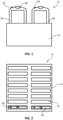
- Figs.1 and 2 illustrate one embodiment of an identification badge system 10 of the present invention.
- the identification badge system 10 of the present invention has a base station 12.
- the base station 12 has at least one docking receptacle 14 for docking a reusable badge 20.
- the base station 12 has 16 docking receptacles 14 for receiving up to 16 reusable badges 20 at one time.
- Other numbers and configurations of docking receptacles 14 are possible without departing from the spirit of the present invention.
- the base station 12 can be connected to a computer (not shown) for providing a user interface with the base station 12. Connection to a computer may be particularly advantageous at a permanent security or reception desk or office of a controlled access building for example. Alternatively, the base station 12 may be adapted to receive any required information for operating on a standalone basis. Such an operation may be particularly applicable at a check-in table at a conference or other large function where a check-in table is set up on a temporary basis.
- the base station 12 may house a single board computer (not shown) that provides a user interface via a web browser.
- the base station 12 is adapted to communicate with an image relaying device (not shown), directly, or indirectly through a computer.
- the image relaying device may be an image capture device, such as a camera or a scanner capable of scanning a photo ID of a visitor or guest.
- the operator of the identification badge system 10 of the present invention would authenticate the identification of the visitor or guest by comparing the photo ID to the face of the visitor or guest.
- the base station 12 can be used to charge the badges.
- the image, along with any other identification, of a visitor or guest may be provided electronically in advance of the visitor or guest arrival.
- the data for the visitor or guest may be relayed to a computer that is connected to the base station.
- the data may be provided to the base station 12 with a portable drive, such as an external hard drive, a thumb drive, or the like.
- the visitor or guest may be provided with a barcode or QR code receipt, for example, for presenting to an operator of the identification badge system 10 of the present invention who can scan it with a barcode reader or QR code reader to produce an image on the reusable badge 20.
- the visitor or guest may be provided with a barcode or QR code receipt, after pre-registering and uploading an electronic image of themselves.
- the reusable badge 20 of the present invention has a housing 22, an e-paper display 24, and a readiness indicator. (In alternative embodiments, a gray-scale e-paper or a black and white e-paper display could be used).
- the readiness indicator is depicted in Figs. 1 - 3 as an indicator light 26. However, it will be understood by those skilled in the art that the readiness indicator may be a lit-up backlight on the e-paper display or an audible signal (not shown), without departing from the spirit of the invention.
- the housing 22 is preferably made of plastic to protect the e-paper display 24, while being lightweight enough so as not to overly burden the visitor or guest.
- the housing 22 is provided with suitable contacts on its base, sides or back for communicating with the base station 12 when the reusable badge 20 is docked in the docking receptacle 14.
- contacts 42 are provided on the front face of the housing 22 for contacting corresponding base station contacts (not shown). It will be understood by those skilled in the art that other numbers or configurations of contacts 42 may be possible.
- the housing 22 is preferably provided with a loop 28 to enable a visitor or guest to carry the reusable badge 20 with a lanyard, strap, clip or the like.
- the e-paper display 24 can be provided with e-ink, which is an electrophoretic display composed of a large number of light and dark nanoparticles suspended between two plates of electrostatically-charged glass. E-paper mimics the appearance of ink in an electronic display.
- the display may be black and white or colored, depending on the requirements and/or wishes of the employer and/or event.
- Suitable electronic displays can be provided by a variety of technologies, including, without limitation, electrophoretic, electrowetting, electrofluidic, interferometric modulator, and plasmonic techniques.
- color transparent film (not shown) can be placed over the display portion of the reusable badge 20, and particularly over at least a portion of the e-paper display 24 such as for non-limiting example the photograph for differentiation of visitors, vendors and other temporary personnel.
- An image 30 of the visitor or guest is transmitted from the image relaying device to the base station 12 and is communicated to the reusable badge 20 when the reusable badge 20 is docked in the base station 12.
- additional information 32 is provided including, without limitation, the visitor or guest name, company name, name of person being visited, phone number of person being visited, expected duration of stay, company logo of visitor or guest, logo of event or company being visited, reason for the visit and the like.
- an identifying symbol such as a bar code 34 or QR code is relayed through the base station 12 to the e-paper display 24.
- the identifying symbol may include further detail on the visitor or guest, authorization to access special events, such as pre-paid lunches, within a larger event, important medical or allergy information, ICE numbers, and the like.
- the indicator light 26 signals that the base station 12 has completed communication of the electronic image 20 and any additional information 32 and/or identifying symbol 34 to the e-paper display 24.
- the indicator light 26 signals that the reusable badge 20 may be removed from the base station 12.
- the e-paper display 24 maintains the electronic image 30 after the reusable badge 20 is removed from the base station 12, without the need for a power supply in the reusable badge 20.
- indicator light 26, or another or additional indicator light can show battery level or power level of the badge and/or can be used for emergency notification, such as for non-limiting example to flash in an emergency.
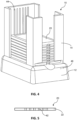
- FIG. 4 and 5 Another embodiment of the identification badge system 10 of the present invention is shown in Figs. 4 and 5 .
- reusable badges 20 are stacked in a single docking receptacle 14.
- Contacts 42 are provided on the base of the reusable badge 20 and are configured to engage corresponding contacts 44 on an inner back face of the docking receptacle 14.
- the readiness indicator is an indicator light 46 on the base station 12.
- the indicator light 46 signals that the reusable badge 20 may be removed from the base station 12.
- the e-paper display 24 maintains the electronic image 30 after the reusable badge 20 is removed from the base station 12, without the need for a power supply in the reusable badge 20.
- the reusable badge 20 has a radio frequency identification tag (“an RFID tag”) (not shown) housed in the housing 22.
- an RFID tag is a HF RFID tag or a UHF RFID tag.
- the RFID tag is adapted to communicate with an RFID reader, for example, equipped within the base station 12.
- the RFID reader may be a separate piece of equipment.
- the base station 12 is equipped with an RFID reader (not shown).
- the RFID tag may be used to provide tracking information, including, without limitation, a time stamp for removing the reusable badge from the base station, a time stamp for re-docking the reusable badge at the base station, electronic image 30 information, electronic identity information associated with the electronic image 30, accountable person information, authentication information, and combinations thereof.
- the RFID tag inside the reusable badge 20 can communicate with standard access control readers, writers, and controllers at secure facilities.
- RFID Radio-frequency identification
- RFID uses electromagnetic fields to automatically identify and track RFID tags attached to objects.
- the electromagnetic fields can be generated by access readers that are usually located near an entryway, for example.
- the generated field activates the RFID tag and causes it to transmit the data stored within it.
- the data is then read by the access readers and later stored.
- This data contains a unique ID number that is used to identify each tag.
- the tracking element of this process is simply logging the date and time of each unique tag when activated and read by a reader fixed at a known location.
- the reusable badge 20 has a Wi-Fi transponder and circuitry for real-time location tracking (RTLS).
- RTLS real-time location tracking
- the reusable badge 20 sends a radio frequency signal to Wi-Fi routers or Bluetooth beacons in a facility.
- This tracking includes real-time location tracking using GPS (Global Positioning System) and can provide for historical location tracking information to be stored in a secure location apart from the digital visitor badge.
- GPS Global Positioning System
- the Wi-Fi location tracking system leverages existing Wi-Fi sources, e.g., routers and access points, to track the location of a visitor badge.
- Wi-Fi sources e.g., routers and access points
- the transponder and associated circuitry inside the badge of the invention use standard Wi-Fi frequencies to detect these sources for which the locations are known.
- Data such as signal strength, atmospheric pressure and SSID (Name associated with a wireless local area network) are gathered and transmitted via the same Wi-Fi infrastructure to software waiting to receive them.
- SSID Name associated with a wireless local area network
- the Wi-Fi tracking system will also take advantage of backscatter to encode information on Wi-Fi signals with little or no energy from a battery.
- Current routers and access points are designed to filter out backscatter as it is considered noise and not used for communications.
- Custom firmware on routers and access points will use a digital envelope detector and low pass filter to extract the encoded information from the received backscatter.
- the badge's ID will be invisibly encoded in the actual housing and read using backscatter.
- the reusable badge 20 is provided with a power supply, for example a battery (not shown) or a capacitor (not shown).
- a power supply for example a battery (not shown) or a capacitor (not shown).
- a capacitor may be provided to hold a charge sufficient to erase the electronic image 30 from the e-paper display 24 if the reusable badge 20 is not re-docked within a prescribed period of time.
- the capacitor may provide a charge sufficient to overwrite the electronic image from the e-paper display if the reusable badge is not re-docked within a prescribed period of time, for example, with a message indicating that the reusable badge 20 has expired, with a pictorial image, a text image, a notice to call a security phone number, a prescribed expiration color, cross-hatching and combinations thereof.
- internal circuitry in the badge is programed or otherwise designed to self-destruct to disable the badge, if and when after activation of the badge, the badge loses connectivity with the facility Wi-Fi, Bluetooth or other electronic communication devices at the facility.
- a battery which may be a reusable battery, is provided, for example, to allow a visitor or guest to access informational or safety information, for example, on a second page of the reusable badge 20, as explained for the embodiments of Figs. 6A and 6B .
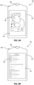
- Figs. 6A and 6B illustrate further embodiments of the reusable badge 20 of the identification badge system 10 of the present invention.
- a finger-swipe for example, to at least one additional display page of the e-paper display 24 showing safety information, for example, a fire escape plan 36, as depicted in Fig. 6A .
- Other types of safety information may include emergency numbers, laboratory safety precautions, information about site-specific dangers, and the like.
- the reusable badge 20 has an internal buzzer for emergency notification.
- the e-paper display 24 defaults back to the electronic image 30 within a prescribed period of time.
- the e-paper display 24 of the present invention can be configured to include at least one additional page for a conference or meeting itinerary 38, as illustrated in Fig. 6B , or other desired information for the visitor.
Landscapes
- Engineering & Computer Science (AREA)
- Physics & Mathematics (AREA)
- General Physics & Mathematics (AREA)
- Theoretical Computer Science (AREA)
- Power Engineering (AREA)
- Human Computer Interaction (AREA)
- General Engineering & Computer Science (AREA)
- Toxicology (AREA)
- Computer Networks & Wireless Communication (AREA)
- Electromagnetism (AREA)
- Health & Medical Sciences (AREA)
- Computer Hardware Design (AREA)
- Computer Security & Cryptography (AREA)
- Microelectronics & Electronic Packaging (AREA)
- General Health & Medical Sciences (AREA)
- Artificial Intelligence (AREA)
- Computer Vision & Pattern Recognition (AREA)
- Alarm Systems (AREA)
- Time Recorders, Dirve Recorders, Access Control (AREA)
- Management, Administration, Business Operations System, And Electronic Commerce (AREA)
- Burglar Alarm Systems (AREA)
- Mobile Radio Communication Systems (AREA)
Claims (16)
- Un système de badge d'identification temporaire/ visiteur pour une utilisation sur site comprenant :- un dispositif de relais d'images pour la transmission de toute image électronique d'une personne ou du nom d'une personne, de son numéro d'identification de dossier ou de tout autre élément d'identification ou renseignement y afférent ;- un indicateur de disponibilité opérationnelle ; et- un badge réutilisable aux caractéristiques suivantes : un boîtier ; un avertisseur sonore ou un dispositif d'alerte par vibration ; un afficheur papier électronique couleur ou un film couleur placé au-dessus d'un afficheur papier électronique noir et blanc ou en nuances de gris ou encore un afficheur papier électronique noir et blanc ; une puce GPS ainsi que son ensemble de circuits connexes pour un Suivi de localisation en temps réel (SLTR) ou suivi de localisation par Système de positionnement global (GPS), ainsi qu'un transpondeur Wi-Fi ou Bluetooth à des fins de communication et de transfert de données avec le badge, y compris toute image électronique d'une personne ou du nom d'une personne, de son numéro d'identification de dossier ou de tout autre élément d'identification ou renseignement y afférent ; ainsi que les composants électriques internes, y compris les composants qui s'autodétruisent physiquement et/ou qui effacent automatiquement les informations, logiciels ou micrologiciels qui se rapportent à l'utilisation du badge réutilisable lorsque le badge, une fois activé, perd sa connectivité avec le Wi-Fi ou le Bluetooth du site ou d'autres dispositifs de communication électronique se trouvant sur ledit site ;- une station de base pour recharger le badge et communiquer avec le dispositif de relais d'images, la station de base disposant d'au moins un réceptacle de chargement ;- un boîtier ayant été adapté pour pouvoir être apparié sur l'au moins un réceptacle de chargement de la station de base, à des fins de chargement du badge et de transmission de l'image électronique de la station de base vers l'afficheur papier électronique lorsque ledit boîtier est apparié sur l'au moins un réceptacle de chargement de la station de base ;- un afficheur papier électronique ayant été adapté pour conserver l'image électronique reçue depuis le dispositif de relais d'images lorsque le badge réutilisable est retiré de l'au moins un réceptacle de chargement de la station de base ;- un indicateur de disponibilité opérationnelle ayant été adapté pour indiquer lorsque la station de base a achevé la transmission de l'image électronique vers le badge réutilisable, procédé au terme duquel le badge réutilisable redevient prêt à l'emploi et peut être retiré de la station de base ;- caractérisé en ce que la station de base est adaptée pour supprimer l'image électronique de l'afficheur papier électronique lorsque le badge réutilisable est réapparié sur l'au moins un réceptacle de chargement de la station de base ;caractérisé en ce que le badge réutilisable comprend, par ailleurs, un marqueur RFID ; etcaractérisé en ce que le badge réutilisable comprend, par ailleurs, une alimentation.
- Suivant la revendication 1, le système de badge d'identification qui comporte, par ailleurs, un espace de stockage distinct du badge ou de la station de base permettant la réception et le stockage d'informations de suivi de localisation du badge.
- Suivant la revendication 1, le système de badge d'identification caractérisé en ce que l'afficheur papier électronique est coloré par superposition d'un film ayant au moins une couleur.
- Suivant la revendication 1, le système de badge d'identification caractérisé en ce que l'afficheur papier électronique est coloré avec de l'encre électronique.
- Suivant la revendication 1, le système de badge d'identification caractérisé en ce que le système est utilisé sur un site doté de lecteurs RFID au niveau des points d'accès du site et que le marqueur RFID du badge réutilisable sert à communiquer avec lesdits lecteurs RFID.
- Suivant la revendication 1, le système de badge d'identification caractérisé en ce que la station de base est équipée, par ailleurs, d'un lecteur RFID pour communiquer avec le marqueur RFID, grâce auquel des informations sont transmises à la station de base, lesdites informations étant sélectionnées parmi un ensemble de données constitué de l'horodatage de retrait du badge réutilisable de la station de base, l'horodatage de réappariement du badge réutilisable à la station de base, des informations relatives aux images électroniques, des informations d'identification électronique associées à l'image électronique, des informations relatives à la personne responsable, des informations d'authentification ainsi que toute autre combinaison des éléments précités.
- Suivant la revendication 1, le système de badge d'identification caractérisé en ce que le marqueur RFID est sélectionné parmi un ensemble d'éléments dont les marqueurs HF RFID, les marqueurs UHF RFID, ainsi que toute autre combinaison des éléments précités.
- Suivant la revendication 1, le système de badge d'identification caractérisé en ce que l'alimentation est un condensateur destiné à maintenir une charge suffisante afin de supprimer l'image électronique de l'afficheur papier électronique si le badge réutilisable n'est pas réapparié dans les délais prédéfinis.
- Suivant la revendication 1, le système de badge d'identification caractérisé en ce que l'alimentation est un condensateur destiné à maintenir une charge suffisante afin de remplacer l'image électronique de l'afficheur papier électronique si le badge réutilisable n'est pas réapparié dans les délais prédéfinis.
- Suivant la revendication 1, le système de badge d'identification caractérisé en ce que l'alimentation est une batterie.
- Suivant la revendication 1, le système de badge d'identification caractérisé en ce que la station de base est également adaptée pour communiquer des informations d'identification supplémentaires au badge réutilisable et que l'afficheur papier électronique comprend également au moins une page supplémentaire d'informations.
- Suivant la revendication 1, le système de badge d'identification caractérisé en ce que le dispositif de relais d'images est sélectionné parmi un ensemble d'éléments dont un scanner, un appareil photo, un lecteur QR, un lecteur de codes-barres, ainsi que toute combinaison des éléments précités.
- Suivant la revendication 1, le système de badge d'identification caractérisé en ce que la station de base a été adaptée pour apparier une multitude de badges réutilisables.
- Suivant la revendication 1, le système de badge d'identification caractérisé en ce que la station de base a été adaptée pour connecter un ordinateur.
- Suivant la revendication 1, le système de badge d'identification caractérisé en ce que le badge réutilisable est équipé d'un indicateur de disponibilité opérationnelle.
- Suivant la revendication 1, le système de badge d'identification caractérisé en ce que la station de base est équipée d'un indicateur de disponibilité opérationnelle.
Applications Claiming Priority (2)
| Application Number | Priority Date | Filing Date | Title |
|---|---|---|---|
| US15/871,889 US10152668B2 (en) | 2017-02-20 | 2018-01-15 | Identification badge system |
| PCT/US2018/058048 WO2019139663A1 (fr) | 2018-01-15 | 2018-10-29 | Système de badge d'identification |
Publications (3)
| Publication Number | Publication Date |
|---|---|
| EP3740940A1 EP3740940A1 (fr) | 2020-11-25 |
| EP3740940B1 true EP3740940B1 (fr) | 2023-07-05 |
| EP3740940C0 EP3740940C0 (fr) | 2023-07-05 |
Family
ID=67219804
Family Applications (1)
| Application Number | Title | Priority Date | Filing Date |
|---|---|---|---|
| EP18804780.7A Active EP3740940B1 (fr) | 2018-01-15 | 2018-10-29 | Système de badge d'identification |
Country Status (9)
| Country | Link |
|---|---|
| US (1) | US20210081741A1 (fr) |
| EP (1) | EP3740940B1 (fr) |
| JP (1) | JP2021510862A (fr) |
| CN (1) | CN111480186A (fr) |
| AU (1) | AU2018401712A1 (fr) |
| CA (1) | CA3087849A1 (fr) |
| GB (1) | GB2582685B (fr) |
| SG (1) | SG11202004571SA (fr) |
| WO (1) | WO2019139663A1 (fr) |
Families Citing this family (5)
| Publication number | Priority date | Publication date | Assignee | Title |
|---|---|---|---|---|
| EP4017736A4 (fr) * | 2019-08-23 | 2023-09-20 | Satellite Displays Inc. | Badge d'interaction reconfigurable |
| WO2021181770A1 (fr) * | 2020-03-13 | 2021-09-16 | 富士フイルム株式会社 | Système de gestion d'informations, procédé de gestion d'informations et programme |
| JP2023021657A (ja) | 2021-08-02 | 2023-02-14 | 東芝テック株式会社 | セキュリティ管理装置 |
| USD1096938S1 (en) | 2022-08-11 | 2025-10-07 | ACCO Brands Corporation | Pocket with surface indicia |
| US20240291659A1 (en) * | 2023-02-24 | 2024-08-29 | Authenticating. Com, LLC | Tokenized Credential Verification System |
Family Cites Families (12)
| Publication number | Priority date | Publication date | Assignee | Title |
|---|---|---|---|---|
| ES2105936B1 (es) * | 1994-03-21 | 1998-06-01 | I D Tec S L | Perfeccionamientos introducidos en la patente de invencion n. p-9400595/8 por: procedimiento biometrico de seguridad y autentificacion de tarjetas de identidad y de credito, visados, pasaportes y reconocimiento facial. |
| US7823773B2 (en) * | 2006-01-31 | 2010-11-02 | CSSN Inc. Catco Scanning Solutions | System and method for creating a badge for a conference or exhibition visitor from a scanned ID document |
| JP4783659B2 (ja) * | 2006-03-30 | 2011-09-28 | 共同印刷株式会社 | Icカード |
| JP2008200949A (ja) * | 2007-02-19 | 2008-09-04 | Kyodo Printing Co Ltd | 表示装置の色表示変更方法及び表示装置 |
| US7733231B2 (en) | 2007-03-30 | 2010-06-08 | Verizon Patent And Licensing Inc. | Security device with display |
| US9002944B2 (en) * | 2007-04-04 | 2015-04-07 | Pathfinders International, Llc | Virtual badge, device and method |
| EP2194490A1 (fr) * | 2008-11-28 | 2010-06-09 | Gemalto SA | Objet portable intelligent comportant des données de personnalisation graphique |
| GB2466026A (en) * | 2008-12-08 | 2010-06-09 | Hisham Mohamed Hassan Mehanna | Identification system with reprogrammable display |
| CN201465203U (zh) * | 2009-05-22 | 2010-05-12 | 北京研博新创科技发展有限公司 | 访客安全管理装置 |
| US20140266590A1 (en) * | 2013-03-14 | 2014-09-18 | Nagraid Security, Inc. | Reconfigurable Smart Identification Badges |
| US9652910B2 (en) * | 2015-06-26 | 2017-05-16 | Fmr Llc | Access system employing dynamic badges |
| WO2018151746A1 (fr) * | 2017-02-20 | 2018-08-23 | Huff Ronald James | Système de badge d'identification |
-
2018
- 2018-01-15 US US16/962,478 patent/US20210081741A1/en active Pending
- 2018-10-29 CA CA3087849A patent/CA3087849A1/fr active Pending
- 2018-10-29 AU AU2018401712A patent/AU2018401712A1/en not_active Abandoned
- 2018-10-29 EP EP18804780.7A patent/EP3740940B1/fr active Active
- 2018-10-29 CN CN201880079741.XA patent/CN111480186A/zh active Pending
- 2018-10-29 GB GB1915045.7A patent/GB2582685B/en active Active
- 2018-10-29 JP JP2020531532A patent/JP2021510862A/ja active Pending
- 2018-10-29 SG SG11202004571SA patent/SG11202004571SA/en unknown
- 2018-10-29 WO PCT/US2018/058048 patent/WO2019139663A1/fr not_active Ceased
Also Published As
| Publication number | Publication date |
|---|---|
| US20210081741A1 (en) | 2021-03-18 |
| AU2018401712A1 (en) | 2020-05-28 |
| CN111480186A (zh) | 2020-07-31 |
| GB2582685B (en) | 2022-09-14 |
| GB201915045D0 (en) | 2019-12-04 |
| SG11202004571SA (en) | 2020-06-29 |
| EP3740940C0 (fr) | 2023-07-05 |
| JP2021510862A (ja) | 2021-04-30 |
| EP3740940A1 (fr) | 2020-11-25 |
| WO2019139663A1 (fr) | 2019-07-18 |
| GB2582685A (en) | 2020-09-30 |
| CA3087849A1 (fr) | 2019-07-18 |
Similar Documents
| Publication | Publication Date | Title |
|---|---|---|
| US10152668B2 (en) | Identification badge system | |
| EP3740940B1 (fr) | Système de badge d'identification | |
| US9836103B2 (en) | Wireless personal tracking device | |
| US8052061B2 (en) | Permanent RFID luggage tag with security features | |
| AU2010244976B2 (en) | Identification device, system and method | |
| US20140191851A1 (en) | Near field communication enabled permanent rfid luggage tag | |
| US11087101B2 (en) | Dual frequency NFC/RFID card for self service baggage check and method | |
| US20040124982A1 (en) | Method for tracking and processing passengers and their transported articles | |
| EP2770482A2 (fr) | Système de commande d'accès au moyen d'un smartphone | |
| EP3485759A1 (fr) | Étiquette de bagage électronique | |
| US20070008138A1 (en) | Coordinated identification of persons and/or articles via radio frequency identification cross-identification | |
| US20090219169A1 (en) | Method and System for Identifying and Handling (Tracing/Locating/Identifying to Receive Services) An Owner And Items In A Secure/Private Area | |
| US10521869B2 (en) | Luggage management system | |
| US20150289087A1 (en) | Passenger and baggage secure access management and tracking system | |
| US20110101096A1 (en) | Identification card and network system using the same | |
| US20170050710A1 (en) | Managing diving activities by wireless data communication | |
| HK40040507B (en) | Identification badge system | |
| HK40040507A (en) | Identification badge system | |
| JP6644503B2 (ja) | 電子名札システム | |
| KR102640445B1 (ko) | 사람 모니터링 시스템 | |
| CN114692117A (zh) | 可携式身份识别装置、电子纸身份识别系统及其操作方法 | |
| Saparkhojayev | RFID-based staff control system (SCS) in Kazakhstan | |
| JP2006018633A (ja) | 就業状況管理システム | |
| Malik et al. | RFID Based Door Lock Security System | |
| Curran et al. | An Investigation into the Reachability of Radio Frequency Identification (RFID) Technologies in Adverse Conditions |
Legal Events
| Date | Code | Title | Description |
|---|---|---|---|
| STAA | Information on the status of an ep patent application or granted ep patent |
Free format text: STATUS: UNKNOWN |
|
| STAA | Information on the status of an ep patent application or granted ep patent |
Free format text: STATUS: THE INTERNATIONAL PUBLICATION HAS BEEN MADE |
|
| PUAI | Public reference made under article 153(3) epc to a published international application that has entered the european phase |
Free format text: ORIGINAL CODE: 0009012 |
|
| STAA | Information on the status of an ep patent application or granted ep patent |
Free format text: STATUS: REQUEST FOR EXAMINATION WAS MADE |
|
| 17P | Request for examination filed |
Effective date: 20200511 |
|
| AK | Designated contracting states |
Kind code of ref document: A1 Designated state(s): AL AT BE BG CH CY CZ DE DK EE ES FI FR GB GR HR HU IE IS IT LI LT LU LV MC MK MT NL NO PL PT RO RS SE SI SK SM TR |
|
| AX | Request for extension of the european patent |
Extension state: BA ME |
|
| DAV | Request for validation of the european patent (deleted) | ||
| DAX | Request for extension of the european patent (deleted) | ||
| REG | Reference to a national code |
Ref country code: HK Ref legal event code: DE Ref document number: 40040507 Country of ref document: HK |
|
| REG | Reference to a national code |
Ref country code: DE Ref legal event code: R079 Free format text: PREVIOUS MAIN CLASS: G07C0009000000 Ipc: G07C0009210000 Ref document number: 602018052920 Country of ref document: DE |
|
| GRAP | Despatch of communication of intention to grant a patent |
Free format text: ORIGINAL CODE: EPIDOSNIGR1 |
|
| STAA | Information on the status of an ep patent application or granted ep patent |
Free format text: STATUS: GRANT OF PATENT IS INTENDED |
|
| RIC1 | Information provided on ipc code assigned before grant |
Ipc: G09G 3/34 20060101ALN20221221BHEP Ipc: H02J 7/00 20060101ALI20221221BHEP Ipc: G07C 9/28 20200101ALI20221221BHEP Ipc: G07C 9/27 20200101ALI20221221BHEP Ipc: G07C 9/21 20200101AFI20221221BHEP |
|
| RIC1 | Information provided on ipc code assigned before grant |
Ipc: G09G 3/34 19800101ALN20230103BHEP Ipc: H02J 7/00 19680901ALI20230103BHEP Ipc: G07C 9/28 20200101ALI20230103BHEP Ipc: G07C 9/27 20200101ALI20230103BHEP Ipc: G07C 9/21 20200101AFI20230103BHEP |
|
| INTG | Intention to grant announced |
Effective date: 20230117 |
|
| GRAS | Grant fee paid |
Free format text: ORIGINAL CODE: EPIDOSNIGR3 |
|
| GRAA | (expected) grant |
Free format text: ORIGINAL CODE: 0009210 |
|
| STAA | Information on the status of an ep patent application or granted ep patent |
Free format text: STATUS: THE PATENT HAS BEEN GRANTED |
|
| AK | Designated contracting states |
Kind code of ref document: B1 Designated state(s): AL AT BE BG CH CY CZ DE DK EE ES FI FR GB GR HR HU IE IS IT LI LT LU LV MC MK MT NL NO PL PT RO RS SE SI SK SM TR |
|
| REG | Reference to a national code |
Ref country code: CH Ref legal event code: EP |
|
| REG | Reference to a national code |
Ref country code: AT Ref legal event code: REF Ref document number: 1585553 Country of ref document: AT Kind code of ref document: T Effective date: 20230715 |
|
| REG | Reference to a national code |
Ref country code: DE Ref legal event code: R096 Ref document number: 602018052920 Country of ref document: DE |
|
| REG | Reference to a national code |
Ref country code: IE Ref legal event code: FG4D |
|
| U01 | Request for unitary effect filed |
Effective date: 20230720 |
|
| U07 | Unitary effect registered |
Designated state(s): AT BE BG DE DK EE FI FR IT LT LU LV MT NL PT SE SI Effective date: 20230726 |
|
| REG | Reference to a national code |
Ref country code: LT Ref legal event code: MG9D |
|
| U20 | Renewal fee for the european patent with unitary effect paid |
Year of fee payment: 6 Effective date: 20231011 |
|
| PG25 | Lapsed in a contracting state [announced via postgrant information from national office to epo] |
Ref country code: GR Free format text: LAPSE BECAUSE OF FAILURE TO SUBMIT A TRANSLATION OF THE DESCRIPTION OR TO PAY THE FEE WITHIN THE PRESCRIBED TIME-LIMIT Effective date: 20231006 |
|
| PG25 | Lapsed in a contracting state [announced via postgrant information from national office to epo] |
Ref country code: ES Free format text: LAPSE BECAUSE OF FAILURE TO SUBMIT A TRANSLATION OF THE DESCRIPTION OR TO PAY THE FEE WITHIN THE PRESCRIBED TIME-LIMIT Effective date: 20230705 |
|
| PG25 | Lapsed in a contracting state [announced via postgrant information from national office to epo] |
Ref country code: IS Free format text: LAPSE BECAUSE OF FAILURE TO SUBMIT A TRANSLATION OF THE DESCRIPTION OR TO PAY THE FEE WITHIN THE PRESCRIBED TIME-LIMIT Effective date: 20231105 |
|
| PG25 | Lapsed in a contracting state [announced via postgrant information from national office to epo] |
Ref country code: RS Free format text: LAPSE BECAUSE OF FAILURE TO SUBMIT A TRANSLATION OF THE DESCRIPTION OR TO PAY THE FEE WITHIN THE PRESCRIBED TIME-LIMIT Effective date: 20230705 Ref country code: NO Free format text: LAPSE BECAUSE OF FAILURE TO SUBMIT A TRANSLATION OF THE DESCRIPTION OR TO PAY THE FEE WITHIN THE PRESCRIBED TIME-LIMIT Effective date: 20231005 Ref country code: IS Free format text: LAPSE BECAUSE OF FAILURE TO SUBMIT A TRANSLATION OF THE DESCRIPTION OR TO PAY THE FEE WITHIN THE PRESCRIBED TIME-LIMIT Effective date: 20231105 Ref country code: HR Free format text: LAPSE BECAUSE OF FAILURE TO SUBMIT A TRANSLATION OF THE DESCRIPTION OR TO PAY THE FEE WITHIN THE PRESCRIBED TIME-LIMIT Effective date: 20230705 Ref country code: GR Free format text: LAPSE BECAUSE OF FAILURE TO SUBMIT A TRANSLATION OF THE DESCRIPTION OR TO PAY THE FEE WITHIN THE PRESCRIBED TIME-LIMIT Effective date: 20231006 Ref country code: ES Free format text: LAPSE BECAUSE OF FAILURE TO SUBMIT A TRANSLATION OF THE DESCRIPTION OR TO PAY THE FEE WITHIN THE PRESCRIBED TIME-LIMIT Effective date: 20230705 |
|
| PG25 | Lapsed in a contracting state [announced via postgrant information from national office to epo] |
Ref country code: PL Free format text: LAPSE BECAUSE OF FAILURE TO SUBMIT A TRANSLATION OF THE DESCRIPTION OR TO PAY THE FEE WITHIN THE PRESCRIBED TIME-LIMIT Effective date: 20230705 |
|
| REG | Reference to a national code |
Ref country code: DE Ref legal event code: R097 Ref document number: 602018052920 Country of ref document: DE |
|
| PG25 | Lapsed in a contracting state [announced via postgrant information from national office to epo] |
Ref country code: SM Free format text: LAPSE BECAUSE OF FAILURE TO SUBMIT A TRANSLATION OF THE DESCRIPTION OR TO PAY THE FEE WITHIN THE PRESCRIBED TIME-LIMIT Effective date: 20230705 Ref country code: RO Free format text: LAPSE BECAUSE OF FAILURE TO SUBMIT A TRANSLATION OF THE DESCRIPTION OR TO PAY THE FEE WITHIN THE PRESCRIBED TIME-LIMIT Effective date: 20230705 Ref country code: CZ Free format text: LAPSE BECAUSE OF FAILURE TO SUBMIT A TRANSLATION OF THE DESCRIPTION OR TO PAY THE FEE WITHIN THE PRESCRIBED TIME-LIMIT Effective date: 20230705 Ref country code: SK Free format text: LAPSE BECAUSE OF FAILURE TO SUBMIT A TRANSLATION OF THE DESCRIPTION OR TO PAY THE FEE WITHIN THE PRESCRIBED TIME-LIMIT Effective date: 20230705 |
|
| PLBE | No opposition filed within time limit |
Free format text: ORIGINAL CODE: 0009261 |
|
| STAA | Information on the status of an ep patent application or granted ep patent |
Free format text: STATUS: NO OPPOSITION FILED WITHIN TIME LIMIT |
|
| PG25 | Lapsed in a contracting state [announced via postgrant information from national office to epo] |
Ref country code: MC Free format text: LAPSE BECAUSE OF FAILURE TO SUBMIT A TRANSLATION OF THE DESCRIPTION OR TO PAY THE FEE WITHIN THE PRESCRIBED TIME-LIMIT Effective date: 20230705 |
|
| REG | Reference to a national code |
Ref country code: CH Ref legal event code: PL |
|
| 26N | No opposition filed |
Effective date: 20240408 |
|
| GBPC | Gb: european patent ceased through non-payment of renewal fee |
Effective date: 20231029 |
|
| PG25 | Lapsed in a contracting state [announced via postgrant information from national office to epo] |
Ref country code: GB Free format text: LAPSE BECAUSE OF NON-PAYMENT OF DUE FEES Effective date: 20231029 |
|
| PG25 | Lapsed in a contracting state [announced via postgrant information from national office to epo] |
Ref country code: CH Free format text: LAPSE BECAUSE OF NON-PAYMENT OF DUE FEES Effective date: 20231031 |
|
| PG25 | Lapsed in a contracting state [announced via postgrant information from national office to epo] |
Ref country code: GB Free format text: LAPSE BECAUSE OF NON-PAYMENT OF DUE FEES Effective date: 20231029 Ref country code: CH Free format text: LAPSE BECAUSE OF NON-PAYMENT OF DUE FEES Effective date: 20231031 |
|
| PG25 | Lapsed in a contracting state [announced via postgrant information from national office to epo] |
Ref country code: IE Free format text: LAPSE BECAUSE OF NON-PAYMENT OF DUE FEES Effective date: 20231029 |
|
| PG25 | Lapsed in a contracting state [announced via postgrant information from national office to epo] |
Ref country code: IE Free format text: LAPSE BECAUSE OF NON-PAYMENT OF DUE FEES Effective date: 20231029 |
|
| U21 | Renewal fee for the european patent with unitary effect paid with additional fee |
Year of fee payment: 7 Effective date: 20250321 |
|
| PG25 | Lapsed in a contracting state [announced via postgrant information from national office to epo] |
Ref country code: CY Free format text: LAPSE BECAUSE OF FAILURE TO SUBMIT A TRANSLATION OF THE DESCRIPTION OR TO PAY THE FEE WITHIN THE PRESCRIBED TIME-LIMIT; INVALID AB INITIO Effective date: 20181029 |
|
| PG25 | Lapsed in a contracting state [announced via postgrant information from national office to epo] |
Ref country code: HU Free format text: LAPSE BECAUSE OF FAILURE TO SUBMIT A TRANSLATION OF THE DESCRIPTION OR TO PAY THE FEE WITHIN THE PRESCRIBED TIME-LIMIT; INVALID AB INITIO Effective date: 20181029 |
|
| PG25 | Lapsed in a contracting state [announced via postgrant information from national office to epo] |
Ref country code: TR Free format text: LAPSE BECAUSE OF FAILURE TO SUBMIT A TRANSLATION OF THE DESCRIPTION OR TO PAY THE FEE WITHIN THE PRESCRIBED TIME-LIMIT Effective date: 20230705 |