EP3740827B1 - Verfahren zum betrieb einer verpackungsmaschine - Google Patents
Verfahren zum betrieb einer verpackungsmaschine Download PDFInfo
- Publication number
- EP3740827B1 EP3740827B1 EP19701986.2A EP19701986A EP3740827B1 EP 3740827 B1 EP3740827 B1 EP 3740827B1 EP 19701986 A EP19701986 A EP 19701986A EP 3740827 B1 EP3740827 B1 EP 3740827B1
- Authority
- EP
- European Patent Office
- Prior art keywords
- load parameter
- packaging
- packaging machine
- drive motor
- parameter
- Prior art date
- Legal status (The legal status is an assumption and is not a legal conclusion. Google has not performed a legal analysis and makes no representation as to the accuracy of the status listed.)
- Active
Links
Images

Classifications
-
- G—PHYSICS
- G05—CONTROLLING; REGULATING
- G05B—CONTROL OR REGULATING SYSTEMS IN GENERAL; FUNCTIONAL ELEMENTS OF SUCH SYSTEMS; MONITORING OR TESTING ARRANGEMENTS FOR SUCH SYSTEMS OR ELEMENTS
- G05B23/00—Testing or monitoring of control systems or parts thereof
- G05B23/02—Electric testing or monitoring
- G05B23/0205—Electric testing or monitoring by means of a monitoring system capable of detecting and responding to faults
- G05B23/0218—Electric testing or monitoring by means of a monitoring system capable of detecting and responding to faults characterised by the fault detection method dealing with either existing or incipient faults
- G05B23/0224—Process history based detection method, e.g. whereby history implies the availability of large amounts of data
- G05B23/0227—Qualitative history assessment, whereby the type of data acted upon, e.g. waveforms, images or patterns, is not relevant, e.g. rule based assessment; if-then decisions
- G05B23/0235—Qualitative history assessment, whereby the type of data acted upon, e.g. waveforms, images or patterns, is not relevant, e.g. rule based assessment; if-then decisions based on a comparison with predetermined threshold or range, e.g. "classical methods", carried out during normal operation; threshold adaptation or choice; when or how to compare with the threshold
-
- B—PERFORMING OPERATIONS; TRANSPORTING
- B65—CONVEYING; PACKING; STORING; HANDLING THIN OR FILAMENTARY MATERIAL
- B65B—MACHINES, APPARATUS OR DEVICES FOR, OR METHODS OF, PACKAGING ARTICLES OR MATERIALS; UNPACKING
- B65B57/00—Automatic control, checking, warning, or safety devices
- B65B57/10—Automatic control, checking, warning, or safety devices responsive to absence, presence, abnormal feed, or misplacement of articles or materials to be packaged
- B65B57/14—Automatic control, checking, warning, or safety devices responsive to absence, presence, abnormal feed, or misplacement of articles or materials to be packaged and operating to control, or stop, the feed of articles or material to be packaged
-
- B—PERFORMING OPERATIONS; TRANSPORTING
- B65—CONVEYING; PACKING; STORING; HANDLING THIN OR FILAMENTARY MATERIAL
- B65B—MACHINES, APPARATUS OR DEVICES FOR, OR METHODS OF, PACKAGING ARTICLES OR MATERIALS; UNPACKING
- B65B57/00—Automatic control, checking, warning, or safety devices
- B65B57/10—Automatic control, checking, warning, or safety devices responsive to absence, presence, abnormal feed, or misplacement of articles or materials to be packaged
- B65B57/16—Automatic control, checking, warning, or safety devices responsive to absence, presence, abnormal feed, or misplacement of articles or materials to be packaged and operating to stop, or to control the speed of, the machine as a whole
-
- B—PERFORMING OPERATIONS; TRANSPORTING
- B65—CONVEYING; PACKING; STORING; HANDLING THIN OR FILAMENTARY MATERIAL
- B65B—MACHINES, APPARATUS OR DEVICES FOR, OR METHODS OF, PACKAGING ARTICLES OR MATERIALS; UNPACKING
- B65B57/00—Automatic control, checking, warning, or safety devices
- B65B57/18—Automatic control, checking, warning, or safety devices causing operation of audible or visible alarm signals
-
- B—PERFORMING OPERATIONS; TRANSPORTING
- B65—CONVEYING; PACKING; STORING; HANDLING THIN OR FILAMENTARY MATERIAL
- B65B—MACHINES, APPARATUS OR DEVICES FOR, OR METHODS OF, PACKAGING ARTICLES OR MATERIALS; UNPACKING
- B65B59/00—Arrangements to enable machines to handle articles of different sizes, to produce packages of different sizes, to vary the contents of packages, to handle different types of packaging material, or to give access for cleaning or maintenance purposes
- B65B59/001—Arrangements to enable adjustments related to the product to be packaged
-
- B—PERFORMING OPERATIONS; TRANSPORTING
- B65—CONVEYING; PACKING; STORING; HANDLING THIN OR FILAMENTARY MATERIAL
- B65B—MACHINES, APPARATUS OR DEVICES FOR, OR METHODS OF, PACKAGING ARTICLES OR MATERIALS; UNPACKING
- B65B65/00—Details peculiar to packaging machines and not otherwise provided for; Arrangements of such details
- B65B65/02—Driving gear
-
- G—PHYSICS
- G05—CONTROLLING; REGULATING
- G05B—CONTROL OR REGULATING SYSTEMS IN GENERAL; FUNCTIONAL ELEMENTS OF SUCH SYSTEMS; MONITORING OR TESTING ARRANGEMENTS FOR SUCH SYSTEMS OR ELEMENTS
- G05B19/00—Program-control systems
- G05B19/02—Program-control systems electric
- G05B19/04—Program control other than numerical control, i.e. in sequence controllers or logic controllers
- G05B19/042—Program control other than numerical control, i.e. in sequence controllers or logic controllers using digital processors
-
- G—PHYSICS
- G05—CONTROLLING; REGULATING
- G05B—CONTROL OR REGULATING SYSTEMS IN GENERAL; FUNCTIONAL ELEMENTS OF SUCH SYSTEMS; MONITORING OR TESTING ARRANGEMENTS FOR SUCH SYSTEMS OR ELEMENTS
- G05B19/00—Program-control systems
- G05B19/02—Program-control systems electric
- G05B19/04—Program control other than numerical control, i.e. in sequence controllers or logic controllers
- G05B19/042—Program control other than numerical control, i.e. in sequence controllers or logic controllers using digital processors
- G05B19/0428—Safety, monitoring
-
- H—ELECTRICITY
- H02—GENERATION; CONVERSION OR DISTRIBUTION OF ELECTRIC POWER
- H02P—CONTROL OR REGULATION OF ELECTRIC MOTORS, ELECTRIC GENERATORS OR DYNAMO-ELECTRIC CONVERTERS; CONTROLLING TRANSFORMERS, REACTORS OR CHOKE COILS
- H02P29/00—Arrangements for regulating or controlling electric motors, appropriate for both AC and DC motors
- H02P29/02—Providing protection against overload without automatic interruption of supply
- H02P29/032—Preventing damage to the motor, e.g. setting individual current limits for different drive conditions
-
- B—PERFORMING OPERATIONS; TRANSPORTING
- B65—CONVEYING; PACKING; STORING; HANDLING THIN OR FILAMENTARY MATERIAL
- B65B—MACHINES, APPARATUS OR DEVICES FOR, OR METHODS OF, PACKAGING ARTICLES OR MATERIALS; UNPACKING
- B65B37/00—Supplying or feeding fluent-solid, plastic, or liquid material, or loose masses of small articles, to be packaged
- B65B37/08—Supplying or feeding fluent-solid, plastic, or liquid material, or loose masses of small articles, to be packaged by rotary feeders
- B65B37/10—Supplying or feeding fluent-solid, plastic, or liquid material, or loose masses of small articles, to be packaged by rotary feeders of screw type
-
- B—PERFORMING OPERATIONS; TRANSPORTING
- B65—CONVEYING; PACKING; STORING; HANDLING THIN OR FILAMENTARY MATERIAL
- B65B—MACHINES, APPARATUS OR DEVICES FOR, OR METHODS OF, PACKAGING ARTICLES OR MATERIALS; UNPACKING
- B65B57/00—Automatic control, checking, warning, or safety devices
- B65B57/10—Automatic control, checking, warning, or safety devices responsive to absence, presence, abnormal feed, or misplacement of articles or materials to be packaged
- B65B57/14—Automatic control, checking, warning, or safety devices responsive to absence, presence, abnormal feed, or misplacement of articles or materials to be packaged and operating to control, or stop, the feed of articles or material to be packaged
- B65B57/145—Automatic control, checking, warning, or safety devices responsive to absence, presence, abnormal feed, or misplacement of articles or materials to be packaged and operating to control, or stop, the feed of articles or material to be packaged for fluent material
-
- G—PHYSICS
- G05—CONTROLLING; REGULATING
- G05B—CONTROL OR REGULATING SYSTEMS IN GENERAL; FUNCTIONAL ELEMENTS OF SUCH SYSTEMS; MONITORING OR TESTING ARRANGEMENTS FOR SUCH SYSTEMS OR ELEMENTS
- G05B2219/00—Program-control systems
- G05B2219/30—Nc systems
- G05B2219/45—Nc applications
- G05B2219/45048—Packaging
Definitions
- the invention relates to a method for operating a packaging machine according to the preamble of claim 1.
- a generic packaging machine is, for example, from DE 10 2010 028 697 A1 known.
- This packaging machine includes in particular a drive motor with which a functional unit, namely a screw conveyor, can be driven.
- a parameter set with a load protection parameter is stored in the controller, which limits the maximum torque that can be applied by the motor or the maximum current that can be drawn by the drive motor.
- the load protection parameter prevents the drive motor from being overloaded, for example if the screw conveyor is blocked.
- Another packaging machine is off DE 10 2013 207 363 A1 known.
- a power limitation of an electric motor by a parameter is off, for example EP 1 168 691 A1 or off EP 3 046 250 A1 known.
- a problem with the known packaging machines is that the packaging machines are used to produce a wide variety of packaging. Depending on the packaging to be produced, the functional unit, which is driven by a drive motor, can then be reconfigured. If, for example, smaller packaging is filled and sealed, the corresponding screw conveyor is installed with a smaller format.
- the problem here is that the load protection parameter, which limits the maximum current consumption or the maximum torque of the respective drive motor, remains unchanged. If there is a malfunction in the functional unit, for example due to the packaging of the powder to be conveyed with the screw conveyor, the limitation of the power to be applied by the drive motor programmed with the load protection parameter is only achieved if there is already considerable damage to the corresponding functional unit, for example due to unscrewing the corresponding small auger, have occurred.
- a parameter set with a load protection parameter is first loaded as usual, which limits the torque or the power consumption of the motor to a predefined maximum during the production of a specific package.
- This predefined maximum power consumption which is represented by the load protection parameter, can be based in particular on the fact that the drive motor itself cannot be overloaded.
- the packaging machine is then put into operation and the respective packaging is produced with the correspondingly necessary functional units of the packaging machine.
- the maximum actual value of the torque occurring at the motor or the maximum actual value of the current consumption occurring at the motor is measured. If the packaging is correspondingly small, this maximum actual value that occurs will usually be significantly below the previously preset load protection parameter.
- a new load protection parameter is then calculated from the measured actual value of the maximum torque that has occurred or the maximum current consumption that has occurred.
- This new load protection parameter then represents the limit of the power consumption of the drive motor, which has to be expended in undisturbed normal operation of the packaging machine when producing the corresponding packaging.
- the new load protection parameter can then be determined slightly above the measured actual values in order to avoid unwanted fault messages when a load protection parameter that has been selected too narrowly is exceeded.
- the new load protection parameter which is derived from the measured actual values of the maximum torques that have occurred or the maximum current consumption that has occurred, is stored in a parameter set that is specifically assigned to the packaging to be produced.
- the specifically assigned set of parameters can be loaded into the control of the packaging machine and damage not only to the drive motor but also to the functional unit driven by the drive motor can be easily ruled out.
- the maximum power consumption that occurred during the manufacture of a package or the maximum torque that occurred during the manufacture of a package can vary within certain tolerance limits.
- the new load protection parameter is determined after the production of a specified minimum number of packages and the corresponding measurement of the maximum actual values that occurred. An average value can then be used from the various maximum actual values to determine the new load protection parameter. As an alternative to this, it is also conceivable to use the largest of the measured maximum actual values to determine the new load protection parameter.
- the new load protection parameter is automatically overwritten.
- the use of the new load protection parameter can also be made dependent on the old load protection parameter being overwritten with the new load protection parameter only after confirmation of a corresponding message by the operator.
- the manner in which the new load protection parameter is determined as a function of the measured actual value is fundamentally arbitrary.
- Known calculation formulas can be used without further ado.
- the new load protection parameter is calculated as a percentage of the maximum measured actual value.
- the new load protection parameter can preferably be 110% or 120% or 130% or 140% or 150% of the maximum measured actual value.
- a warning message is issued when a first load protection parameter is exceeded. If the measured actual value exceeds, for example, a load protection parameter of 110% of the maximum actual value measured according to the invention, a warning message is first displayed to the operator, which indicates a possible problem due to the increased load.
- a fault message is output when a second load protection parameter is exceeded, for example 130% of the maximum actual value measured using the method according to the invention.
- an emergency stop signal can be output in order to automatically stop the machine and prevent damage to the mechanical functional units due to undesired overloads .
- a dosing device 01 is outlined, which is part of a packaging machine 15.
- the dosing device 01 has a dispensing container 02, which consists of a funnel 03 and a tube 04 connected to it.
- a stirrer 06 and a dosing screw 05 Arranged on it is a stirrer 06 and a dosing screw 05.
- funnel 03, tube 04 and stirrer 06 and dosing screw 05 have a common central axis.
- a gap 08 is provided between the stirrer 06 and the funnel 03 . This is chosen to be as small as possible according to the function, but large enough to prevent contact between the stirrer 06 and the funnel 03. The same applies to the gap 07 between the tube 04 and the dosing screw 05.
- the screw conveyor 05 is driven by a drive motor 09.
- a load protection parameter 10 (see 2 ) is stored, which is intended to prevent damage to the drive motor 09 due to overload.
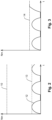
- FIG. 2 shows the measurement diagram for measuring the torque applied by the drive motor 09, which acts on the conveyor spindle 05, during the production of packaging 11.
- the actual value 12 of the torque to be applied during the production of the packaging 11 rises periodically up to a maximum value 13 and then falls back to the zero value. With each new pack 11 becomes a new one Pass through the value cycle of the torque applied to the conveyor spindle 05.
- the maximum actual value 13 of the torque applied by the drive motor 09 is considerably below the load protection parameter 10 stored in the controller. If the actual torque 12 were to rise above the maximum value 13 reached during normal operation in the event of a fault, for example when packaging the powder to be conveyed, a fault would only be recognized by the controller when the load protection parameter 10 was reached, in which case this would already be the case significant mechanical damage to the screw conveyor would have occurred.
- the maximum value 13 measured during normal operation is used to determine a new load protection parameter 14 .
- the new load protection parameter 14 is 110% of the maximum value 13 measured during normal operation of the torque applied by the drive motor 09. In other words, this means that this power threshold is not exceeded during normal operation when the packaging 11 is being produced. Exceeds as in 3 shown as an example, the actual value 12 the new load protection parameter 14, a warning message, a fault message or an emergency stop signal can be sent. After appropriate confirmation by the operating personnel, the new load protection parameter 14 is stored in the parameter set assigned to the packaging 11 and overwrites the old load protection parameter 10.
Landscapes
- Engineering & Computer Science (AREA)
- Mechanical Engineering (AREA)
- Physics & Mathematics (AREA)
- General Physics & Mathematics (AREA)
- Automation & Control Theory (AREA)
- Power Engineering (AREA)
- Control Of Electric Motors In General (AREA)
Description
- Die Erfindung betrifft ein Verfahren zum Betrieb einer Verpackungsmaschine nach dem Oberbegriff des Anspruchs 1.
- Eine gattungsgemäße Verpackungsmaschine ist beispielsweise aus der
DE 10 2010 028 697 A1 bekannt. Diese Verpackungsmaschine umfasst insbesondere einen Antriebsmotor, mit dem eine Funktionseinheit, nämlich eine Förderschnecke angetrieben werden kann. Bei gattungsgemäßen Verpackungsmaschinen ist in der Steuerung ein Parametersatz mit einem Lastschutzparameter hinterlegt, der das vom Motor maximal aufbringbare Drehmoment bzw. den vom Antriebsmotor maximal aufzunehmenden Strom begrenzt. Durch den Lastschutzparameter wird eine Überlastung des Antriebsmotors, wie sie beispielsweise beim Blockieren der Förderschnecke auftreten könnte, ausgeschlossen. - Eine weitere Verpackungsmaschine ist beispielsweise aus
DE 10 2013 207 363 A1 bekannt. Eine Leistungsbegrenzung eines Elektromotors durch einen Parameter ist beispielsweise ausEP 1 168 691 A1 oder ausEP 3 046 250 A1 bekannt. - Bei den bekannten Verpackungsmaschinen ist es ein Problem, dass mit den Verpackungsmaschinen unterschiedlichste Verpackungen hergestellt werden. Abhängig von der jeweils herzustellenden Verpackung kann dann die Funktionseinheit, die mit einem Antriebsmotor angetrieben wird, umgebaut werden. Werden beispielsweise kleinere Verpackungen befüllt und versiegelt, so wird die entsprechende Förderschnecke mit einem geringeren Format eingebaut. Problematisch ist es dabei, dass der Lastschutzparameter, der die maximale Stromaufnahme bzw. das maximale Drehmoment des jeweiligen Antriebsmotors begrenzt, unverändert bleibt. Kommt es nun an der Funktionseinheit zu einer Funktionsstörung, beispielsweise durch Verpacken des mit der Förderschnecke zu fördernden Pulvers, so wird die mit dem Lastschutzparameter programmierte Begrenzung der vom Antriebsmotor aufzubringenden Leistung erst dann erreicht, wenn bereits erhebliche Beschädigungen an der entsprechenden Funktionseinheit, beispielsweise durch Herausdrehen der entsprechenden kleinen Förderschnecke, aufgetreten sind.
- Ausgehend von diesem Stand der Technik ist es Aufgabe der vorliegenden Erfindung ein neues Verfahren zum Betrieb einer Verpackungsmaschine vorzuschlagen, mit dem die oben beschriebenen Nachteile vermieden werden.
- Vorteilhafte Ausführungsformen der Erfindung sind Gegenstand der Unteransprüche.
- Bei dem erfindungsgemäßen Verfahren wird zunächst wie üblich ein Parametersatz mit einem Lastschutzparameter geladen, der das Drehmoment oder die Stromaufnahme des Motors bei der Herstellung einer bestimmten Verpackung auf ein vordefiniertes Maximum begrenzt. Dieses vordefinierte Maximum der Leistungsaufnahme, die durch den Lastschutzparameter repräsentiert wird, kann sich insbesondere daran orientieren, dass eine Überlastung des Antriebsmotors selbst ausgeschlossen ist.
- Anschließend wird die Verpackungsmaschine in Betrieb gesetzt und die jeweiligen Verpackungen mit den entsprechend notwendigen Funktionseinheiten der Verpackungsmaschine hergestellt. Während des Betriebs der Verpackungsmaschine zur Herstellung der Verpackung wird der maximal auftretende Ist-Wert des am Motor auftretenden Drehmoments bzw. der maximal auftretende Ist-Wert der am Motor auftretenden Stromaufnahme gemessen. Handelt es sich um entsprechend kleine Verpackungen, wird dieser maximal auftretende Ist-Wert üblicherweise signifikant unterhalb des bisher voreingestellten Lastschutzparameters liegen.
- Im nächsten Schritt wird dann aus dem gemessenen Ist-Wert des maximal aufgetretenen Drehmoments bzw. der maximal aufgetretenen Stromaufnahme ein neuer Lastschutzparameter berechnet. Dieser neue Lastschutzparameter repräsentiert dann gerade die Grenze der Leistungsaufnahme des Antriebsmotors, die im ungestörten Normalbetrieb der Verpackungsmaschine bei der Herstellung der entsprechenden Verpackungen aufgewendet werden muss. Der neue Lastschutzparameter kann dann selbstverständlich etwas oberhalb der gemessenen Ist-Werte bestimmt werden, um ungewollte Störmeldungen bei Überschreiten eines zu eng gewählten Lastschutzparameters zu vermeiden.
- Zuletzt wird der neue Lastschutzparameter, der aus den gemessenen Ist-Werten der maximal aufgetretenen Drehmomente bzw. der maximal aufgetretenen Stromaufnahme abgeleitet ist, in einem der herzustellenden Verpackungen spezifisch zugeordneten Parametersatz abgespeichert. Während des weiteren Betriebs der Verpackungsmaschine kann dann immer, wenn eine entsprechende Verpackung mit der Verpackungsmaschine hergestellt werden soll, der spezifisch zugeordnete Parametersatz in die Steuerung der Verpackungsmaschine geladen und dadurch Beschädigungen nicht nur des Antriebsmotors sondern auch der mit dem Antriebsmotor angetriebenen Funktionseinheit problemlos ausgeschlossen werden.
- Die bei der Herstellung einer Verpackung maximal aufgetretene Stromaufnahme bzw. das bei der Herstellung einer Verpackung maximal aufgetretene Drehmoment kann innerhalb bestimmter Toleranzgrenzen streuen. Um solche Streueffekte bei der Bestimmung des neuen Lastschutzparameters berücksichtigen zu können, ist es besonders vorteilhaft, wenn der neue Lastschutzparameter nach Herstellung einer vorgegebenen Mindestanzahl von Verpackungen und der entsprechenden Messung der dabei aufgetretenen maximalen Ist-Werte bestimmt wird. Aus den verschiedenen maximalen Ist-Werten kann dann ein Durchschnittswert zur Bestimmung des neuen Lastschutzparameters genutzt werden. Alternativ dazu ist es auch denkbar, den größten der gemessenen maximalen Ist-Werte zur Bestimmung des neuen Lastschutzparameters zu nutzen.
- Für die Weiterverwendung des neuen Lastschutzparameters gibt es unterschiedliche Vorgehensstrategien. Gemäß einer ersten Verfahrensvariante wird nach Bestimmung eines neuen Lastschutzparameters zu einer bestimmten Verpackung der alte Lastschutzparameter automatisch überschrieben.
- Alternativ zu der automatischen Überschreibung des alten Lastschutzparameters kann die Verwendung des neuen Lastschutzparameters auch davon abhängig gemacht werden, dass das Überschreiben des alten Lastschutzparameters mit dem neuen Lastschutzparameter erst nach Bestätigung einer entsprechenden Meldung durch den Bediener erfolgt.
- In welcher Weise der neue Lastschutzparameter in Abhängigkeit des gemessenen Ist-Werts bestimmt wird, ist grundsätzlich beliebig. Ohne Weiteres können dazu bekannte Berechnungsformeln eingesetzt werden. Eine besonders einfache und leicht verständliche Berechnungsformel liegt in der Verwendung einer linearen Formel F (neuer Lastschutzparameter) = f (maximaler Ist-Wert).
- Gemäß einer bevorzugten Ausführungsvariante ist es vorgesehen, dass der neue Lastschutzparameter als Prozentualwert des maximal gemessenen Ist-Werts berechnet wird. Bevorzugt kann der neue Lastschutzparameter 110 % oder 120 % oder 130 % oder 140 % oder 150 % des maximal gemessenen Ist-Werts sein.
- Wird bei der Herstellung einer Verpackung der neu gespeicherte Lastschutzparameter überschritten, so können damit unterschiedliche Reaktionen ausgelöst werden. Gemäß einer ersten Variante wird bei Überschreiten eines ersten Lastschutzparameters eine Warnmeldung ausgegeben. Überschreitet der gemessene Ist-Wert beispielsweise einen Lastschutzparameter von 110 % des erfindungsgemäß gemessenen maximalen Ist-Werts, so wird dem Bediener zunächst eine Warnmeldung angezeigt, die auf ein mögliches Problem aufgrund der erhöhten Belastung hinweist.
- Gemäß einer zweiten Verfahrensalternative ist es vorgesehen, dass bei Überschreiten eines zweiten Lastschutzparameters, beispielsweise von 130 % des mit dem erfindungsgemäßen Verfahren maximal gemessenen Ist-Werts eine Störmeldung ausgegeben wird.
- Gemäß einer dritten Verfahrensalternative kann bei Überschreiten des vierten Lastschutzparameters, beispielsweise von 150 % des mit dem erfindungsgemäßen Verfahrens maximal gemessenen Ist-Werts ein Not-Aus-Signal ausgegeben werden, um die Maschine automatisch zu stoppen und Beschädigungen in den mechanischen Funktionseinheiten durch unerwünschte Überlastungen auszuschließen.
- Eine Ausführungsform der Erfindung ist in den Zeichnungen schematisiert dargestellt und wird nachfolgend beispielhaft erläutert.
- Es zeigen:
- Fig. 1
- eine schematisiert dargestellte Verpackungsmaschine mit einer von einem Antriebsmotor angetriebenen Förderspindel;
- Fig. 2
- ein schematisiert dargestelltes Messdiagramm zur Darstellung des gemessenen Ist-Drehmoments des Antriebsmotors;
- Fig. 3
- ein Messdiagramm gemäß
Fig. 2 nach Bestimmung eines neuen Lastschutzparameters. - In
Fig. 1 ist eine Dosiervorrichtung 01 skizziert, die Teil einer Verpackungsmaschine 15 ist. Hierbei weist die Dosiervorrichtung 01 ein Abgabebehältnis 02 auf, welches aus einem Trichter 03 und einem daran anschließenden Rohr 04 besteht. Daran angeordnet befindet sich ein Rührer 06 sowie eine Dosierschnecke 05. Wie in der Skizze zu erkennen ist, weisen Trichter 03, Rohr 04 sowie Rührer 06 und Dosierschnecke 05 eine gemeinsame Mittelachse auf. - Zwischen dem Rührer 06 und dem Trichter 03 ist ein Spalt 08 vorgesehen. Dieser wird funktionsgemäß möglichst klein gewählt, jedoch groß genug, um einen Kontakt zwischen dem Rührer 06 und dem Trichter 03 zu verhindern. Gleiches gilt für den Spalt 07 zwischen dem Rohr 04 und der Dosierschnecke 05.
- Dennoch ist bei Wahl eines geringen Spalts 07 bzw. 08 eine Kollision der entsprechenden Teile nicht auszuschließen.
- Die Förderschnecke 05 wird mit einem Antriebsmotor 09 angetrieben. Für diesen Antriebsmotor 09 ist in der Steuerung der Verpackungsmaschine 15 ein Lastschutzparameter 10 (siehe
Fig. 2 ) abgespeichert, der eine Beschädigung des Antriebsmotors 09 durch Überlastung verhindern soll. -
Fig. 2 zeigt das Messdiagramm zur Messung vom Antriebsmotor 09 aufgebrachtem Drehmoment, das auf die Förderspindel 05 wirkt, während der Herstellung von Verpackungen 11. Der bei der Herstellung der Verpackungen 11 aufzubringende Ist-Wert 12 des Drehmoments steigt periodisch bis zu einem Maximal-Wert 13 an und fällt dann wieder auf den Null-Wert zurück. Mit jeder neuen Verpackung 11 wird ein neuer Wertzyklus des an der Förderspindel 05 aufgebrachten Drehmoments durchlaufen. - Man erkennt, dass der maximale Ist-Wert 13 des vom Antriebsmotor 09 aufgebrachten Drehmoments erheblich unterhalb des in der Steuerung hinterlegten Lastschutzparameters 10 liegt. Würde das Ist-Drehmoment 12 bei einer Störung, beispielsweise beim Verpacken des zu fördernden Pulvers, über den im Normalbetrieb erreichten Maximal-Wert 13 ansteigen, so würde eine Störung durch die Steuerung erst bei Erreichen des Lastschutzparameters 10 erkannt, wobei in diesem Fall dann bereits erhebliche mechanische Beschädigungen an der Förderschnecke aufgetreten sein würden.
- Um solche Beschädigungen auszuschließen, wird der im Normalbetrieb gemessene Maximal-Wert 13 zur Bestimmung eines neuen Lastschutzparameters 14 genutzt.
- Wie in
Fig. 3 dargestellt, liegt der neue Lastschutzparameter 14 bei 110 % des im Normalbetrieb gemessenen Maximal-Werts 13 des vom Antriebsmotor 09 aufgebrachten Drehmoments. Dies bedeutet mit anderen Worten, dass diese Leistungsschwelle im Normalbetrieb bei der Herstellung der Verpackungen 11 nicht überschritten wird. Überschreitet, wie inFig. 3 beispielhaft dargestellt, der Ist-Wert 12 den neuen Lastschutzparameter 14, so kann eine Warnmeldung, eine Störmeldung oder ein Not-Aus-Signal abgesetzt werden. Der neue Lastschutzparameter 14 wird nach entsprechender Bestätigung durch das Bedienpersonal im Parametersatz, der der Verpackung 11 zugeordnet ist, abgespeichert und überschreibt den alten Lastschutzparameter 10.
Claims (9)
- Verfahren zum Betrieb einer Verpackungsmaschine (15) mit zumindest einem elektrischen Antriebsmotor (09), wobei der Antriebmotor (09) zumindest eine Funktionseinheit (05) der Verpackungsmaschine (15) bei der Herstellung von Verpackungen (11) programmgesteuert antreibt mit folgenden Verfahrensschritten:a) Laden eines Parametersatzes in die Steuerung der Verpackungsmaschine (15), wobei der Parametersatz zumindest einen alten Lastschutzparameter (10) enthält, der das Drehmoment oder die Stromaufnahme des Antriebsmotor (09) bei der Herstellung der Verpackungen (11) auf ein Maximum begrenzt;b) Betrieb der Verpackungsmaschine (15) unter Herstellung der Verpackung (11), wobei während des Betriebs der maximal auftretende Ist-Wert (13) des am Antriebsmotor (09) auftretenden Drehmoments oder der am Antriebsmotor (09) auftretenden Stromaufnahme gemessen wird;gekennzeichnet durch die folgenden Verfahrensschritte:c) Bestimmung eines neuen Lastschutzparameters (14) in Abhängigkeit des maximalen Ist-Wertes;d) Speicherung des neuen Lastschutzparameters (14) in einem der herzustellenden Verpackung (11) zugeordneten Parametersatz.
- Verfahren nach Anspruch 1,
dadurch gekennzeichnet,
dass der neue Lastschutzparameter (14) nach Herstellung einer vorgegebenen Mindestanzahl von Verpackung bestimmt wird. - Verfahren nach Anspruch 1 oder 2,
dadurch gekennzeichnet,
dass der alte Lastschutzparameter (13) automatisch mit dem neuen Lastschutzparameter (14) überschrieben wird. - Verfahren nach Anspruch 1 oder 2,
dadurch gekennzeichnet,
dass der alte Lastschutzparameter (13) nach Bestätigung einer entsprechenden Meldung durch den Bediener mit dem neuen Lastschutzparameter (14) überschrieben wird. - Verfahren nach einem der Ansprüche 1 bis 4,
dadurch gekennzeichnet,
dass der neue Lastschutzparameter (14) mit einer linearen Formel in Abhängigkeit vom maximalen Ist-Wert (13) berechnet wird. - Verfahren nach Anspruch 5,
dadurch gekennzeichnet,
dass der neue Lastschutzparameter (14) 110 % oder 120 % oder 130 % oder 140 % oder 150 % des maximalen Ist-Werts (13) entspricht. - Verfahren nach einem der Ansprüche 1 bis 6,
dadurch gekennzeichnet,
dass bei Überschreiten eines ersten Lastschutzparameters während des Betriebs der Verpackungsmaschine (15) eine Warnmeldung ausgegeben wird. - Verfahren nach einem der Ansprüche 1 bis 7,
dadurch gekennzeichnet,
dass bei Überschreiten eines zweiten Lastschutzparameters während des Betriebs der Verpackungsmaschine (15) eine Störmeldung ausgegeben wird. - Verfahren nach einem der Ansprüche 1 bis 8,
dadurch gekennzeichnet,
dass bei Überschreiten eines dritten Lastschutzparameters während des Betriebs der Verpackungsmaschine (15) ein Not-Aus-Signal ausgegeben wird.
Applications Claiming Priority (2)
| Application Number | Priority Date | Filing Date | Title |
|---|---|---|---|
| DE102018101180.6A DE102018101180B4 (de) | 2018-01-19 | 2018-01-19 | Verfahren zum Betrieb einer Verpackungsmaschine |
| PCT/EP2019/050447 WO2019141566A1 (de) | 2018-01-19 | 2019-01-09 | Verfahren zum betrieb einer verpackungsmaschine |
Publications (3)
| Publication Number | Publication Date |
|---|---|
| EP3740827A1 EP3740827A1 (de) | 2020-11-25 |
| EP3740827C0 EP3740827C0 (de) | 2023-06-07 |
| EP3740827B1 true EP3740827B1 (de) | 2023-06-07 |
Family
ID=65236982
Family Applications (1)
| Application Number | Title | Priority Date | Filing Date |
|---|---|---|---|
| EP19701986.2A Active EP3740827B1 (de) | 2018-01-19 | 2019-01-09 | Verfahren zum betrieb einer verpackungsmaschine |
Country Status (5)
| Country | Link |
|---|---|
| US (1) | US11340600B2 (de) |
| EP (1) | EP3740827B1 (de) |
| DE (1) | DE102018101180B4 (de) |
| PL (1) | PL3740827T3 (de) |
| WO (1) | WO2019141566A1 (de) |
Family Cites Families (21)
| Publication number | Priority date | Publication date | Assignee | Title |
|---|---|---|---|---|
| US3616968A (en) * | 1969-04-10 | 1971-11-02 | Hayssen Mfg Co | Auger filler and control therefor |
| JP3331024B2 (ja) * | 1993-10-13 | 2002-10-07 | ファナック株式会社 | 工具寿命管理方式 |
| JP3473861B2 (ja) | 1993-12-28 | 2003-12-08 | 株式会社イシダ | 包材の封止部に介在する介在物の有無の判定方法 |
| AU6151096A (en) | 1995-06-07 | 1996-12-30 | Tetra Laval Holdings & Finance Sa | Diagnostic system for a servomotor driven apparatus |
| US5587931A (en) * | 1995-10-20 | 1996-12-24 | Tri-Way Machine Ltd. | Tool condition monitoring system |
| US5836136A (en) * | 1997-03-18 | 1998-11-17 | Kliklok Corporation | Seal integrity monitoring and adaptive control method and apparatus |
| DE10031925A1 (de) | 2000-06-30 | 2002-01-10 | Bosch Gmbh Robert | Elektromotor, insbesondere Wischermotor |
| JP2007028865A (ja) | 2005-07-21 | 2007-02-01 | Matsushita Electric Ind Co Ltd | モータ制御装置 |
| EP1757522B1 (de) | 2005-08-26 | 2009-05-06 | Tipper Tie Alpina AG | Verfahren und Clipvorrichtung zum Verschliessen wurstförmiger Verpackungen |
| ES2320782T3 (es) * | 2005-10-07 | 2009-05-28 | Emotron Ab | Monitor de carga. |
| ATE453951T1 (de) * | 2005-11-29 | 2010-01-15 | Siemens Ag | Überwachungseinheit zur lastüberwachung eines elektrischen motors |
| JP2008046972A (ja) * | 2006-08-18 | 2008-02-28 | Toyota Motor Corp | 駆動装置、走行装置及び駆動装置の制御方法 |
| US7675257B2 (en) * | 2007-03-09 | 2010-03-09 | Regal Beloit Corporation | Methods and systems for recording operating information of an electronically commutated motor |
| DE102010028697B3 (de) | 2010-05-06 | 2011-11-10 | Rovema Gmbh | Dosiervorrichtung mit Schadensüberwachung |
| EP2436602A1 (de) * | 2010-10-01 | 2012-04-04 | Bühler AG | Vorrichtung und Verfahren zum Dosieren eines Schüttguts |
| DE102013207363A1 (de) * | 2013-04-23 | 2014-10-23 | Rovema Gmbh | Dosiervorrichtung zum Dosieren eines fließfähigen Produkts |
| US10287046B2 (en) * | 2014-10-28 | 2019-05-14 | Omron Corporation | Control apparatus, system, and program library |
| DE102015000086A1 (de) | 2015-01-13 | 2016-07-14 | Baumüller Nürnberg GmbH | Verfahren zur Drehmomentüberwachung und Umrichter |
| JP6348095B2 (ja) * | 2015-11-13 | 2018-06-27 | ファナック株式会社 | 電動機システムを選定するための選定装置、ネットワークシステム、及び方法 |
| DE102016208670B4 (de) | 2016-05-19 | 2018-07-05 | Rovema Gmbh | Verfahren zur Herstellung von Verpackungen mittels einer Verpackungsmaschine mit SPS-Steuerung |
| DE102017128628A1 (de) * | 2017-12-01 | 2019-06-06 | Point 8 Gmbh | Verfahren zum Erfassen mindestens eines Werkzeugzustands eines Werkzeugs einer Werkzeugmaschine zur Bearbeitung von Werkstücken sowie Werkzeugmaschine |
-
2018
- 2018-01-19 DE DE102018101180.6A patent/DE102018101180B4/de not_active Revoked
-
2019
- 2019-01-09 US US16/962,924 patent/US11340600B2/en active Active
- 2019-01-09 WO PCT/EP2019/050447 patent/WO2019141566A1/de not_active Ceased
- 2019-01-09 EP EP19701986.2A patent/EP3740827B1/de active Active
- 2019-01-09 PL PL19701986.2T patent/PL3740827T3/pl unknown
Also Published As
| Publication number | Publication date |
|---|---|
| EP3740827C0 (de) | 2023-06-07 |
| WO2019141566A1 (de) | 2019-07-25 |
| US20210141370A1 (en) | 2021-05-13 |
| DE102018101180A1 (de) | 2019-07-25 |
| PL3740827T3 (pl) | 2023-10-23 |
| EP3740827A1 (de) | 2020-11-25 |
| DE102018101180B4 (de) | 2019-10-10 |
| US11340600B2 (en) | 2022-05-24 |
Similar Documents
| Publication | Publication Date | Title |
|---|---|---|
| DE3310484C1 (de) | Verfahren zur Erzielung eines maximalen Ausstosses eines Doppelschneckenextruders | |
| EP2314384B1 (de) | Auspressvorrichtung | |
| DE3883757T2 (de) | Anomalie-detektor in spritzgiessmaschine. | |
| EP2480322A1 (de) | Programmgesteuertes rührgerät sowie verfahren zu dessen betrieb | |
| DE102008020116A1 (de) | Einteilstern zum Zu- oder Abführen von Behältern | |
| EP2535570B1 (de) | Windnachführungsanordnung einer Windenergieanlage. | |
| DE69912711T2 (de) | Batterieabkopplungssystem | |
| EP3258197B1 (de) | Anordnung zum entfeuchten von granulatförmigem schüttgut und verfahren hierfür | |
| DE19937472C1 (de) | Verfahren zur Variatorschlupfbehandlung bei stufenlosen Automatgetrieben | |
| EP3272004B1 (de) | Verfahren zur kollisionsüberwachung | |
| DE102018101180B4 (de) | Verfahren zum Betrieb einer Verpackungsmaschine | |
| DE2517027A1 (de) | Schneckenstrangpresse | |
| EP0729822A1 (de) | Steuerungsverfahren für Extrudiermaschinen | |
| EP3313654B1 (de) | Verfahren zur ermittlung einer einsatzkennzahl eines presswerkzeugs in einer fügepresse | |
| EP3853679B1 (de) | Verfahren zur zustandsanalyse eines elektromechanischen fügesystems und elektromechanisches fügesystem zur durchführung dieses verfahrens | |
| EP3302920B1 (de) | Verfahren für die schrittweise führung eines maschinenbedieners einer extrusionsvorrichtung beim wechsel von einer einsatzrezeptur auf eine folgerezeptur | |
| WO2016198221A1 (de) | Verfahren für die vorbereitung eines materialwechsels bei einer extrusionsvorrichtung für eine folienmaschine | |
| DE2750584C2 (de) | Schrämmaschine mit Wechselgetriebe zum Antrieb der Schrämwalze o.dgl. | |
| AT516793A1 (de) | Zellenradschleuse und Sandungsanlage für ein Schienenfahrzeug mit verbessertem Ansprechverhalten | |
| DE102013207363A1 (de) | Dosiervorrichtung zum Dosieren eines fließfähigen Produkts | |
| EP2511777A1 (de) | Verfahren zum Betrieb einer Antriebssteuerungseinrichtung und Antriebssteuerungseinrichtung mit Mitteln zur Verwendung in einem solchen Verfahren | |
| EP0548140B1 (de) | Vorrichtung zum austausch von schmiermittel eines aggregats | |
| EP1050708A2 (de) | Steuerungsvorrichtung und Verfahren zur Steuerung sicherheitsrelevanter Funktionen einer gefahrbringenden Maschine | |
| DE102005040132A1 (de) | Verfahren, graphische Benutzerschnittstelle und Antrieb | |
| DE3348324C1 (en) | Process for obtaining maximum output from a twin-screw extruder |
Legal Events
| Date | Code | Title | Description |
|---|---|---|---|
| STAA | Information on the status of an ep patent application or granted ep patent |
Free format text: STATUS: UNKNOWN |
|
| STAA | Information on the status of an ep patent application or granted ep patent |
Free format text: STATUS: THE INTERNATIONAL PUBLICATION HAS BEEN MADE |
|
| PUAI | Public reference made under article 153(3) epc to a published international application that has entered the european phase |
Free format text: ORIGINAL CODE: 0009012 |
|
| STAA | Information on the status of an ep patent application or granted ep patent |
Free format text: STATUS: REQUEST FOR EXAMINATION WAS MADE |
|
| 17P | Request for examination filed |
Effective date: 20200813 |
|
| AK | Designated contracting states |
Kind code of ref document: A1 Designated state(s): AL AT BE BG CH CY CZ DE DK EE ES FI FR GB GR HR HU IE IS IT LI LT LU LV MC MK MT NL NO PL PT RO RS SE SI SK SM TR |
|
| AX | Request for extension of the european patent |
Extension state: BA ME |
|
| DAV | Request for validation of the european patent (deleted) | ||
| DAX | Request for extension of the european patent (deleted) | ||
| GRAP | Despatch of communication of intention to grant a patent |
Free format text: ORIGINAL CODE: EPIDOSNIGR1 |
|
| STAA | Information on the status of an ep patent application or granted ep patent |
Free format text: STATUS: GRANT OF PATENT IS INTENDED |
|
| RIC1 | Information provided on ipc code assigned before grant |
Ipc: H02P 29/032 20160101ALN20220621BHEP Ipc: B65B 65/02 20060101ALN20220621BHEP Ipc: B65B 59/00 20060101ALN20220621BHEP Ipc: B65B 57/16 20060101ALN20220621BHEP Ipc: B65B 57/14 20060101ALN20220621BHEP Ipc: B65B 37/10 20060101ALN20220621BHEP Ipc: G05B 23/02 20060101ALI20220621BHEP Ipc: G05B 19/042 20060101AFI20220621BHEP |
|
| INTG | Intention to grant announced |
Effective date: 20220706 |
|
| GRAJ | Information related to disapproval of communication of intention to grant by the applicant or resumption of examination proceedings by the epo deleted |
Free format text: ORIGINAL CODE: EPIDOSDIGR1 |
|
| STAA | Information on the status of an ep patent application or granted ep patent |
Free format text: STATUS: REQUEST FOR EXAMINATION WAS MADE |
|
| INTC | Intention to grant announced (deleted) | ||
| RIC1 | Information provided on ipc code assigned before grant |
Ipc: H02P 29/032 20160101ALN20221115BHEP Ipc: B65B 65/02 20060101ALN20221115BHEP Ipc: B65B 59/00 20060101ALN20221115BHEP Ipc: B65B 57/16 20060101ALN20221115BHEP Ipc: B65B 57/14 20060101ALN20221115BHEP Ipc: B65B 37/10 20060101ALN20221115BHEP Ipc: G05B 23/02 20060101ALI20221115BHEP Ipc: G05B 19/042 20060101AFI20221115BHEP |
|
| GRAP | Despatch of communication of intention to grant a patent |
Free format text: ORIGINAL CODE: EPIDOSNIGR1 |
|
| STAA | Information on the status of an ep patent application or granted ep patent |
Free format text: STATUS: GRANT OF PATENT IS INTENDED |
|
| RIC1 | Information provided on ipc code assigned before grant |
Ipc: H02P 29/032 20160101ALN20221212BHEP Ipc: B65B 65/02 20060101ALN20221212BHEP Ipc: B65B 59/00 20060101ALN20221212BHEP Ipc: B65B 57/16 20060101ALN20221212BHEP Ipc: B65B 57/14 20060101ALN20221212BHEP Ipc: B65B 37/10 20060101ALN20221212BHEP Ipc: G05B 23/02 20060101ALI20221212BHEP Ipc: G05B 19/042 20060101AFI20221212BHEP |
|
| INTG | Intention to grant announced |
Effective date: 20230103 |
|
| GRAS | Grant fee paid |
Free format text: ORIGINAL CODE: EPIDOSNIGR3 |
|
| GRAA | (expected) grant |
Free format text: ORIGINAL CODE: 0009210 |
|
| STAA | Information on the status of an ep patent application or granted ep patent |
Free format text: STATUS: THE PATENT HAS BEEN GRANTED |
|
| AK | Designated contracting states |
Kind code of ref document: B1 Designated state(s): AL AT BE BG CH CY CZ DE DK EE ES FI FR GB GR HR HU IE IS IT LI LT LU LV MC MK MT NL NO PL PT RO RS SE SI SK SM TR |
|
| REG | Reference to a national code |
Ref country code: GB Ref legal event code: FG4D Free format text: NOT ENGLISH |
|
| REG | Reference to a national code |
Ref country code: CH Ref legal event code: EP Ref country code: AT Ref legal event code: REF Ref document number: 1576946 Country of ref document: AT Kind code of ref document: T Effective date: 20230615 |
|
| REG | Reference to a national code |
Ref country code: DE Ref legal event code: R096 Ref document number: 502019007984 Country of ref document: DE |
|
| U01 | Request for unitary effect filed |
Effective date: 20230614 |
|
| U07 | Unitary effect registered |
Designated state(s): AT BE BG DE DK EE FI FR IT LT LU LV MT NL PT SE SI Effective date: 20230622 |
|
| REG | Reference to a national code |
Ref country code: LT Ref legal event code: MG9D |
|
| PG25 | Lapsed in a contracting state [announced via postgrant information from national office to epo] |
Ref country code: NO Free format text: LAPSE BECAUSE OF FAILURE TO SUBMIT A TRANSLATION OF THE DESCRIPTION OR TO PAY THE FEE WITHIN THE PRESCRIBED TIME-LIMIT Effective date: 20230907 Ref country code: ES Free format text: LAPSE BECAUSE OF FAILURE TO SUBMIT A TRANSLATION OF THE DESCRIPTION OR TO PAY THE FEE WITHIN THE PRESCRIBED TIME-LIMIT Effective date: 20230607 |
|
| PG25 | Lapsed in a contracting state [announced via postgrant information from national office to epo] |
Ref country code: RS Free format text: LAPSE BECAUSE OF FAILURE TO SUBMIT A TRANSLATION OF THE DESCRIPTION OR TO PAY THE FEE WITHIN THE PRESCRIBED TIME-LIMIT Effective date: 20230607 Ref country code: HR Free format text: LAPSE BECAUSE OF FAILURE TO SUBMIT A TRANSLATION OF THE DESCRIPTION OR TO PAY THE FEE WITHIN THE PRESCRIBED TIME-LIMIT Effective date: 20230607 Ref country code: GR Free format text: LAPSE BECAUSE OF FAILURE TO SUBMIT A TRANSLATION OF THE DESCRIPTION OR TO PAY THE FEE WITHIN THE PRESCRIBED TIME-LIMIT Effective date: 20230908 |
|
| U20 | Renewal fee for the european patent with unitary effect paid |
Year of fee payment: 6 Effective date: 20231204 |
|
| PG25 | Lapsed in a contracting state [announced via postgrant information from national office to epo] |
Ref country code: SK Free format text: LAPSE BECAUSE OF FAILURE TO SUBMIT A TRANSLATION OF THE DESCRIPTION OR TO PAY THE FEE WITHIN THE PRESCRIBED TIME-LIMIT Effective date: 20230607 |
|
| PG25 | Lapsed in a contracting state [announced via postgrant information from national office to epo] |
Ref country code: IS Free format text: LAPSE BECAUSE OF FAILURE TO SUBMIT A TRANSLATION OF THE DESCRIPTION OR TO PAY THE FEE WITHIN THE PRESCRIBED TIME-LIMIT Effective date: 20231007 |
|
| PG25 | Lapsed in a contracting state [announced via postgrant information from national office to epo] |
Ref country code: SM Free format text: LAPSE BECAUSE OF FAILURE TO SUBMIT A TRANSLATION OF THE DESCRIPTION OR TO PAY THE FEE WITHIN THE PRESCRIBED TIME-LIMIT Effective date: 20230607 Ref country code: SK Free format text: LAPSE BECAUSE OF FAILURE TO SUBMIT A TRANSLATION OF THE DESCRIPTION OR TO PAY THE FEE WITHIN THE PRESCRIBED TIME-LIMIT Effective date: 20230607 Ref country code: RO Free format text: LAPSE BECAUSE OF FAILURE TO SUBMIT A TRANSLATION OF THE DESCRIPTION OR TO PAY THE FEE WITHIN THE PRESCRIBED TIME-LIMIT Effective date: 20230607 Ref country code: IS Free format text: LAPSE BECAUSE OF FAILURE TO SUBMIT A TRANSLATION OF THE DESCRIPTION OR TO PAY THE FEE WITHIN THE PRESCRIBED TIME-LIMIT Effective date: 20231007 Ref country code: CZ Free format text: LAPSE BECAUSE OF FAILURE TO SUBMIT A TRANSLATION OF THE DESCRIPTION OR TO PAY THE FEE WITHIN THE PRESCRIBED TIME-LIMIT Effective date: 20230607 |
|
| REG | Reference to a national code |
Ref country code: DE Ref legal event code: R097 Ref document number: 502019007984 Country of ref document: DE |
|
| PLBE | No opposition filed within time limit |
Free format text: ORIGINAL CODE: 0009261 |
|
| STAA | Information on the status of an ep patent application or granted ep patent |
Free format text: STATUS: NO OPPOSITION FILED WITHIN TIME LIMIT |
|
| 26N | No opposition filed |
Effective date: 20240308 |
|
| PG25 | Lapsed in a contracting state [announced via postgrant information from national office to epo] |
Ref country code: MC Free format text: LAPSE BECAUSE OF FAILURE TO SUBMIT A TRANSLATION OF THE DESCRIPTION OR TO PAY THE FEE WITHIN THE PRESCRIBED TIME-LIMIT Effective date: 20230607 |
|
| PG25 | Lapsed in a contracting state [announced via postgrant information from national office to epo] |
Ref country code: MC Free format text: LAPSE BECAUSE OF FAILURE TO SUBMIT A TRANSLATION OF THE DESCRIPTION OR TO PAY THE FEE WITHIN THE PRESCRIBED TIME-LIMIT Effective date: 20230607 |
|
| GBPC | Gb: european patent ceased through non-payment of renewal fee |
Effective date: 20240109 |
|
| PG25 | Lapsed in a contracting state [announced via postgrant information from national office to epo] |
Ref country code: GB Free format text: LAPSE BECAUSE OF NON-PAYMENT OF DUE FEES Effective date: 20240109 |
|
| PG25 | Lapsed in a contracting state [announced via postgrant information from national office to epo] |
Ref country code: GB Free format text: LAPSE BECAUSE OF NON-PAYMENT OF DUE FEES Effective date: 20240109 |
|
| U20 | Renewal fee for the european patent with unitary effect paid |
Year of fee payment: 7 Effective date: 20241128 |
|
| PG25 | Lapsed in a contracting state [announced via postgrant information from national office to epo] |
Ref country code: IE Free format text: LAPSE BECAUSE OF NON-PAYMENT OF DUE FEES Effective date: 20240109 |
|
| PG25 | Lapsed in a contracting state [announced via postgrant information from national office to epo] |
Ref country code: IE Free format text: LAPSE BECAUSE OF NON-PAYMENT OF DUE FEES Effective date: 20240109 |
|
| PG25 | Lapsed in a contracting state [announced via postgrant information from national office to epo] |
Ref country code: CY Free format text: LAPSE BECAUSE OF FAILURE TO SUBMIT A TRANSLATION OF THE DESCRIPTION OR TO PAY THE FEE WITHIN THE PRESCRIBED TIME-LIMIT; INVALID AB INITIO Effective date: 20190109 |
|
| PG25 | Lapsed in a contracting state [announced via postgrant information from national office to epo] |
Ref country code: HU Free format text: LAPSE BECAUSE OF FAILURE TO SUBMIT A TRANSLATION OF THE DESCRIPTION OR TO PAY THE FEE WITHIN THE PRESCRIBED TIME-LIMIT; INVALID AB INITIO Effective date: 20190109 |
|
| U20 | Renewal fee for the european patent with unitary effect paid |
Year of fee payment: 8 Effective date: 20251215 |
|
| REG | Reference to a national code |
Ref country code: CH Ref legal event code: U11 Free format text: ST27 STATUS EVENT CODE: U-0-0-U10-U11 (AS PROVIDED BY THE NATIONAL OFFICE) Effective date: 20260201 |
|
| PGFP | Annual fee paid to national office [announced via postgrant information from national office to epo] |
Ref country code: TR Payment date: 20260108 Year of fee payment: 8 |
|
| PGFP | Annual fee paid to national office [announced via postgrant information from national office to epo] |
Ref country code: CH Payment date: 20260201 Year of fee payment: 8 |
|
| PGFP | Annual fee paid to national office [announced via postgrant information from national office to epo] |
Ref country code: PL Payment date: 20260108 Year of fee payment: 8 |