EP3740377B1 - Verfahren zum herstellen von komponenten einer windenergieanlage, insbesondere eines windenergieanlagen-rotorblattes - Google Patents
Verfahren zum herstellen von komponenten einer windenergieanlage, insbesondere eines windenergieanlagen-rotorblattes Download PDFInfo
- Publication number
- EP3740377B1 EP3740377B1 EP19700929.3A EP19700929A EP3740377B1 EP 3740377 B1 EP3740377 B1 EP 3740377B1 EP 19700929 A EP19700929 A EP 19700929A EP 3740377 B1 EP3740377 B1 EP 3740377B1
- Authority
- EP
- European Patent Office
- Prior art keywords
- component
- wind turbine
- vacuum
- winding core
- wound
- Prior art date
- Legal status (The legal status is an assumption and is not a legal conclusion. Google has not performed a legal analysis and makes no representation as to the accuracy of the status listed.)
- Active
Links
Images







Classifications
-
- B—PERFORMING OPERATIONS; TRANSPORTING
- B29—WORKING OF PLASTICS; WORKING OF SUBSTANCES IN A PLASTIC STATE IN GENERAL
- B29C—SHAPING OR JOINING OF PLASTICS; SHAPING OF MATERIAL IN A PLASTIC STATE, NOT OTHERWISE PROVIDED FOR; AFTER-TREATMENT OF THE SHAPED PRODUCTS, e.g. REPAIRING
- B29C70/00—Shaping composites, i.e. plastics material comprising reinforcements, fillers or preformed parts, e.g. inserts
- B29C70/04—Shaping composites, i.e. plastics material comprising reinforcements, fillers or preformed parts, e.g. inserts comprising reinforcements only, e.g. self-reinforcing plastics
- B29C70/28—Shaping operations therefor
- B29C70/40—Shaping or impregnating by compression not applied
- B29C70/42—Shaping or impregnating by compression not applied for producing articles of definite length, i.e. discrete articles
- B29C70/44—Shaping or impregnating by compression not applied for producing articles of definite length, i.e. discrete articles using isostatic pressure, e.g. pressure difference-moulding, vacuum bag-moulding, autoclave-moulding or expanding rubber-moulding
- B29C70/443—Shaping or impregnating by compression not applied for producing articles of definite length, i.e. discrete articles using isostatic pressure, e.g. pressure difference-moulding, vacuum bag-moulding, autoclave-moulding or expanding rubber-moulding and impregnating by vacuum or injection
-
- B—PERFORMING OPERATIONS; TRANSPORTING
- B29—WORKING OF PLASTICS; WORKING OF SUBSTANCES IN A PLASTIC STATE IN GENERAL
- B29C—SHAPING OR JOINING OF PLASTICS; SHAPING OF MATERIAL IN A PLASTIC STATE, NOT OTHERWISE PROVIDED FOR; AFTER-TREATMENT OF THE SHAPED PRODUCTS, e.g. REPAIRING
- B29C70/00—Shaping composites, i.e. plastics material comprising reinforcements, fillers or preformed parts, e.g. inserts
- B29C70/04—Shaping composites, i.e. plastics material comprising reinforcements, fillers or preformed parts, e.g. inserts comprising reinforcements only, e.g. self-reinforcing plastics
- B29C70/28—Shaping operations therefor
- B29C70/30—Shaping by lay-up, i.e. applying fibres, tape or broadsheet on a mould, former or core; Shaping by spray-up, i.e. spraying of fibres on a mould, former or core
- B29C70/32—Shaping by lay-up, i.e. applying fibres, tape or broadsheet on a mould, former or core; Shaping by spray-up, i.e. spraying of fibres on a mould, former or core on a rotating mould, former or core
-
- B—PERFORMING OPERATIONS; TRANSPORTING
- B29—WORKING OF PLASTICS; WORKING OF SUBSTANCES IN A PLASTIC STATE IN GENERAL
- B29C—SHAPING OR JOINING OF PLASTICS; SHAPING OF MATERIAL IN A PLASTIC STATE, NOT OTHERWISE PROVIDED FOR; AFTER-TREATMENT OF THE SHAPED PRODUCTS, e.g. REPAIRING
- B29C70/00—Shaping composites, i.e. plastics material comprising reinforcements, fillers or preformed parts, e.g. inserts
- B29C70/04—Shaping composites, i.e. plastics material comprising reinforcements, fillers or preformed parts, e.g. inserts comprising reinforcements only, e.g. self-reinforcing plastics
- B29C70/28—Shaping operations therefor
- B29C70/40—Shaping or impregnating by compression not applied
- B29C70/42—Shaping or impregnating by compression not applied for producing articles of definite length, i.e. discrete articles
- B29C70/44—Shaping or impregnating by compression not applied for producing articles of definite length, i.e. discrete articles using isostatic pressure, e.g. pressure difference-moulding, vacuum bag-moulding, autoclave-moulding or expanding rubber-moulding
- B29C70/446—Moulding structures having an axis of symmetry or at least one channel, e.g. tubular structures, frames
-
- B—PERFORMING OPERATIONS; TRANSPORTING
- B29—WORKING OF PLASTICS; WORKING OF SUBSTANCES IN A PLASTIC STATE IN GENERAL
- B29K—INDEXING SCHEME ASSOCIATED WITH SUBCLASSES B29B, B29C OR B29D, RELATING TO MOULDING MATERIALS OR TO MATERIALS FOR MOULDS, REINFORCEMENTS, FILLERS OR PREFORMED PARTS, e.g. INSERTS
- B29K2105/00—Condition, form or state of moulded material or of the material to be shaped
- B29K2105/06—Condition, form or state of moulded material or of the material to be shaped containing reinforcements, fillers or inserts
- B29K2105/08—Condition, form or state of moulded material or of the material to be shaped containing reinforcements, fillers or inserts of continuous length, e.g. cords, rovings, mats, fabrics, strands or yarns
- B29K2105/0872—Prepregs
-
- B—PERFORMING OPERATIONS; TRANSPORTING
- B29—WORKING OF PLASTICS; WORKING OF SUBSTANCES IN A PLASTIC STATE IN GENERAL
- B29L—INDEXING SCHEME ASSOCIATED WITH SUBCLASS B29C, RELATING TO PARTICULAR ARTICLES
- B29L2031/00—Other particular articles
- B29L2031/08—Blades for rotors, stators, fans, turbines or the like, e.g. screw propellers
- B29L2031/082—Blades, e.g. for helicopters
- B29L2031/085—Wind turbine blades
-
- F—MECHANICAL ENGINEERING; LIGHTING; HEATING; WEAPONS; BLASTING
- F03—MACHINES OR ENGINES FOR LIQUIDS; WIND, SPRING, OR WEIGHT MOTORS; PRODUCING MECHANICAL POWER OR A REACTIVE PROPULSIVE THRUST, NOT OTHERWISE PROVIDED FOR
- F03D—WIND MOTORS
- F03D1/00—Wind motors with rotation axis substantially parallel to the air flow entering the rotor
- F03D1/06—Rotors
- F03D1/065—Rotors characterised by their construction elements
- F03D1/0675—Rotors characterised by their construction elements of the blades
-
- F—MECHANICAL ENGINEERING; LIGHTING; HEATING; WEAPONS; BLASTING
- F05—INDEXING SCHEMES RELATING TO ENGINES OR PUMPS IN VARIOUS SUBCLASSES OF CLASSES F01-F04
- F05B—INDEXING SCHEME RELATING TO WIND, SPRING, WEIGHT, INERTIA OR LIKE MOTORS, TO MACHINES OR ENGINES FOR LIQUIDS COVERED BY SUBCLASSES F03B, F03D AND F03G
- F05B2230/00—Manufacture
- F05B2230/20—Manufacture essentially without removing material
-
- Y—GENERAL TAGGING OF NEW TECHNOLOGICAL DEVELOPMENTS; GENERAL TAGGING OF CROSS-SECTIONAL TECHNOLOGIES SPANNING OVER SEVERAL SECTIONS OF THE IPC; TECHNICAL SUBJECTS COVERED BY FORMER USPC CROSS-REFERENCE ART COLLECTIONS [XRACs] AND DIGESTS
- Y02—TECHNOLOGIES OR APPLICATIONS FOR MITIGATION OR ADAPTATION AGAINST CLIMATE CHANGE
- Y02E—REDUCTION OF GREENHOUSE GAS [GHG] EMISSIONS, RELATED TO ENERGY GENERATION, TRANSMISSION OR DISTRIBUTION
- Y02E10/00—Energy generation through renewable energy sources
- Y02E10/70—Wind energy
- Y02E10/72—Wind turbines with rotation axis in wind direction
-
- Y—GENERAL TAGGING OF NEW TECHNOLOGICAL DEVELOPMENTS; GENERAL TAGGING OF CROSS-SECTIONAL TECHNOLOGIES SPANNING OVER SEVERAL SECTIONS OF THE IPC; TECHNICAL SUBJECTS COVERED BY FORMER USPC CROSS-REFERENCE ART COLLECTIONS [XRACs] AND DIGESTS
- Y02—TECHNOLOGIES OR APPLICATIONS FOR MITIGATION OR ADAPTATION AGAINST CLIMATE CHANGE
- Y02P—CLIMATE CHANGE MITIGATION TECHNOLOGIES IN THE PRODUCTION OR PROCESSING OF GOODS
- Y02P70/00—Climate change mitigation technologies in the production process for final industrial or consumer products
- Y02P70/50—Manufacturing or production processes characterised by the final manufactured product
Definitions
- the present invention relates to a method for producing components of a wind power plant.
- Components of wind turbines such as parts of the rotor blades of the wind turbine, can be manufactured using different methods.
- the parts or elements of the wind energy installation can be wound at least partially in a winding process.
- Textile scrims are wrapped around a contouring core.
- the scrims can be impregnated with resin, can be configured as prepreg, or can be used as dry scrims.
- FIG. 14 shows a schematic representation of the winding process.
- a winding core 320 can be placed on a shaft 310 .
- the shaft 310 is rotated so that the winding core 320 also rotates.
- a wound scrim 500 can then be wound onto the winding core 320 in order to obtain a desired component 400 .
- This winding method makes it possible for the outer contour of the winding core 320 to be transferred to the inner contour or the inside of the component.
- DE 27 19 773 describes a method for producing a green body.
- a fiber material is wound on a core form and an outer jacket is applied outside. Air is then sucked out and an impregnating resin is pressed in. The green body is then cured and the core mold is removed from the hollow body. The outer jacket can then be removed mechanically.
- German Patent and Trademark Office has researched the following documents in the German patent application on which priority is based: DE 37 16 335A1 , DE 10 2010 026 018 A1 , DE 10 2015 204 490 A1 , DE 10 2016 110 848 A1 and EP 2 361 752 A1 .
- WO 03/035380 A1 shows a method for manufacturing a rotor blade.
- This object is achieved by a method for producing a component of a wind turbine according to claim 1.
- a method for producing a component of a wind energy plant, in particular a wind energy plant rotor blade, is therefore provided.
- a winding core is provided on a rotatable shaft.
- a vacuum foil is placed on the winding core.
- a component to be manufactured is wound on the vacuum foil using a winding structure.
- An outer shape is placed around the wrapped part.
- a vacuum infusion process is performed and the infused resin is cured.
- a vacuum is created between the vacuum foil on the winding core and the inside of the outer mold, so that the fabric is pressed against the inside of the outer mold by means of the vacuum infusion process, so that a smooth outer surface of the wound part is achieved.
- the mandrel is removed before the vacuum infusion procedure is performed. This is advantageous because it means that the winding core can already be used elsewhere.
- the outer shape is designed in multiple parts.
- the finished wound component can be separated to provide separate individual segments.
- the invention relates to the idea of providing a method for producing components of a wind energy installation, in particular a rotor blade of a wind energy installation.
- a winding core is provided and a wound scrim is wound onto the core.
- An outer mold is then placed on the wound scrim and a vacuum is created so that the scrim is pressed against the inside of the outer mold by means of the vacuum infusion process, so that a smooth outer surface of the wound part is achieved.
- the winding core is removed prior to the vacuum infusion process so that the winding core can be reused in the meantime.
- waves and creases on the outside or outside surface of the component to be produced can be avoided, since due to the vacuum infusion method the scrim is pressed against the outer mold and thus tightened.
- the outer mold can be designed in multiple parts, so that the component to be produced can be easily removed.
- the finished component can be separated into various individual parts.
- the wind power plant 100 has a tower 102 and a nacelle 104 .
- a rotor 106 with three rotor blades 200 and a spinner 110 is provided on the nacelle 104 .
- the rotor 106 is rotated by the wind and drives a generator in the nacelle 104 to produce electrical energy.
- the rotor blade 200 has at least one component 350 which is produced according to the invention.
- FIGS 2 to 9 show schematically different steps in the production of a component for a wind turbine.
- a winding unit 300 with a shaft 310 and a winding core 320 is shown. Rotating the shaft 310 also rotates the winding core.
- a vacuum foil 330 may be provided around the hub 320 .
- a flow grid structure 340 around the vacuum foil 330 is shown.
- a scrim is wrapped around the winding core 320 with the vacuum foil 330 and the flow grid structure 340, so that a component 350 to be produced is wound.
- the component 350 can have a first end 351 and a second end 352, wherein the second end 352 can be configured at least partially in the shape of a cone.
- an outer mold 360 is placed around the winding core 320 and the wound component 350.
- the winding core 320 can be completely removed with the shaft 310, so that only the outer mold 360 with the component 350 located therein remains.
- the outer mold can be removed with the component and a vacuum infusion process can be performed to infuse the layup of the wound component with resin.
- the resin can then be cured so that in the end the finished component 350 as shown in 11 is obtained to see.
- the outer shape can be designed in at least two parts.
- the outer shape can also be designed in multiple parts.
- the component 350 can be configured in multiple parts by separating the wound component into individual parts.
- a vacuum foil 330 is thus placed on the winding core 320 according to the invention. This is sealed to the outer mould, which, as described above, is inherently vacuum-tight.
- a further vacuum foil can optionally be provided between the component and the outer mold, so that a vacuum can be generated between the vacuum foil and the outer mold. This can cause the scrim 350 to relax outwardly.
- the mandrel 320 is removed before resin can diffuse into the scrim using the vacuum infusion process. This is advantageous according to the invention because it allows the component to have an outer contour that is free of waves and folds.
- the thickness of the wound scrim is typically smaller than the distance between the winding core and the inside of the outer mold, so that the scrim is pressed against an inner wall of the outer mould, and a gap can thus arise between the scrim and the outer wall of the winding core 320.
- the structure is thus tightened from the inside out and the winding core 320 can be removed in a simple manner.
- the outer mold 360 can be removed from the mandrel.
- the winding core 320 can then be reused in the meantime in order to produce another component 350 .
- the outer shape 360 can be designed in one piece.
- the outer mold can be designed in several parts, so that the individual parts of the outer mold can be removed separately.
- blade connection areas of a wind turbine rotor blade can be produced using preform segments.
- These preform segments can be manufactured according to the invention. This can be avoided that the components have defects in the form of folds or compressions on the outer contour. According to the invention, this is achieved, inter alia, by using the vacuum infusion method.
- the invention relates in particular to the use of a (multi-part) positive outer mold in order to produce wound components with a defined outer geometry.
- the component to be produced can represent inner and outer flange thickenings, preform segments and inner rotor blades.
- spar boxes can be produced using the method according to the invention.
- the method according to the invention allows rotor blade components to be manufactured effectively and without defects.
- cutting capacities and component shapes can be saved.
- fitting accuracy of the individual parts to one another and to adjacent shapes can be significantly improved.
Landscapes
- Engineering & Computer Science (AREA)
- Chemical & Material Sciences (AREA)
- Mechanical Engineering (AREA)
- Composite Materials (AREA)
- Life Sciences & Earth Sciences (AREA)
- Sustainable Development (AREA)
- Sustainable Energy (AREA)
- Combustion & Propulsion (AREA)
- General Engineering & Computer Science (AREA)
- Wind Motors (AREA)
- Moulding By Coating Moulds (AREA)
Description
- Die vorliegende Erfindung betrifft ein Verfahren zum Herstellen von Komponenten einer Windenergieanlage.
- Komponenten von Windenergieanlagen wie beispielsweise Teile der Rotorblätter der Windenergieanlage können mit unterschiedlichen Verfahren hergestellt werden. Hierbei können die Teile oder Elemente der Windenergieanlage zumindest teilweise in einem Wickelverfahren gewickelt werden. Hierbei werden textile Gelege um einen konturgebenden Kern gewickelt. Die Gelege können mit Harz getränkt sein, können als Prepreg ausgestaltet sein oder können als trockene Gelege verwendet werden.
-
Fig. 14 zeigt eine schematische Darstellung des Wickelverfahrens. Hierbei kann ein Wickelkern 320 auf einer Welle 310 platziert sein. Die Welle 310 wird in Rotation versetzt, so dass auch der Wickelkern 320 rotiert. Ein Wickelgelege 500 kann dann auf den Wickelkern 320 aufgewickelt werden, um ein gewünschtes Bauteil 400 zu erhalten. Durch dieses Wickelverfahren kann erreicht werden, dass die Außenkontur des Wickelkerns 320 auf die Innenkontur bzw. die Innenseite des Bauteils übertragen wird. - Dies kann jedoch dazu führen, dass eine Außengeometrie des Bauteils nicht die gewünschte Außenkontur erhält.
-
DE 27 19 773 beschreibt ein Verfahren zum Herstellen eines Rohkörpers. Ein Fasermaterial wird auf einen Kernform gewickelt und ein Außenmantel wird außen angebracht. Anschließend wird Luft abgesaugt und ein Imprägnierharz wird eingepresst. Der Rohkörper wird dann ausgehärtet und die Kernform wird aus dem Hohlkörper entfernt. Anschließend kann der Außenmantel mechanisch abgetragen werden. - In der prioritätsbegründenden deutschen Patentanmeldung hat das Deutsche Patent-und Markenamt die folgenden Dokumente recherchiert:
DE 37 16 335A1 ,DE 10 2010 026 018 A1 ,DE 10 2015 204 490 A1 ,DE 10 2016 110 848 A1 undEP 2 361 752 A1 . -
DE 103 04 044 A1 zeigt ein Verfahren zum Herstellen von Rohren. -
WO 03/035380 A1 - Es ist eine Aufgabe der vorliegenden Erfindung, die vorstehend angeführten Nachteile zu beheben. Es ist insbesondere eine Aufgabe der vorliegenden Erfindung, ein Verfahren zur effektiveren Herstellung von Komponenten einer Windenergieanlage vorzusehen. Es ist insbesondere eine Aufgabe der vorliegenden Erfindung, ein Verfahren zum Herstellen von Komponenten einer Windenergieanlage vorzusehen, bei welchem auch eine Außengeometrie des herzustellenden Bauteils ausreichend eben bzw. glatt wird.
- Diese Aufgabe wird durch ein Verfahren zum Herstellen eines Bauteils einer Windenergieanlage nach Anspruch 1 gelöst.
- Somit wird ein Verfahren zum Herstellen eines Bauteils einer Windenergieanlage, insbesondere eines Windenergieanlagen-Rotorblattes, vorgesehen. Ein Wickelkern wird auf einer drehbaren Welle vorgesehen. Eine Vakuumfolie wird auf dem Wickelkern platziert. Ein herzustellendes Bauteil wird auf der Vakuumfolie mittels eines Wickelgeleges gewickelt. Eine Außenform wird um das gewickelte Bauteil platziert. Ein Vakuuminfusionsverfahren wird durchgeführt und das infundierte Harz wird ausgehärtet. Hierbei wird ein Vakuum zwischen der Vakuumfolie auf dem Wickelkern und der Innenseite der Außenform erzeugt, so dass das Gelege mittels des Vakuuminfusionsverfahrens gegen die Innenseite der Außenform gepresst wird, so dass eine glatte Außenoberfläche des gewickelten Teils erreicht wird.
- Der Wickelkern wird entfernt, bevor das Vakuuminfusionsverfahren durchgeführt wird. Dies ist vorteilhaft, weil damit der Wickelkern bereits anderweitig verwendet werden kann.
- Gemäß einem Aspekt der vorliegenden Erfindung ist die Außenform mehrteilig ausgestaltet.
- Gemäß einem weiteren Aspekt der vorliegenden Erfindung kann das fertige gewickelte Bauteil getrennt werden, um getrennte Einzelsegmente vorzusehen.
- Die Erfindung betrifft den Gedanken, ein Verfahren zum Herstellen von Komponenten einer Windenergieanlage, insbesondere eines Rotorblatts einer Windenergieanlage, vorzusehen. Dazu wird ein Wickelkern vorgesehen und ein Wickelgelege wird auf den Kern aufgewickelt. Anschließend wird eine Außenform auf dem gewickelten Gelege platziert und ein Vakuum wird erzeugt, so dass das Gelege mittels des Vakuuminfusionsverfahrens gegen die Innenseite der Außenform gepresst wird, so dass eine glatte Außenoberfläche des gewickelten Teils erreicht wird.
- Der Wickelkern wird vor dem Vakuuminfusionsverfahren entfernt, so dass der Wickelkern zwischenzeitlich weiterverwendet werden kann. Durch das erfindungsgemäße Verfahren können Wellen und Falten an der Außenseite bzw. Außenoberfläche des herzustellenden Bauteils vermieden werden, da auf Grund des Vakuuminfusionsverfahrens das Gelege gegen die Außenform gedrückt und damit gestrafft wird.
- Gemäß einem Aspekt der vorliegenden Erfindung kann die Außenform mehrteilig ausgestaltet sein, so dass das herzustellende Bauteil leicht entfernt werden kann.
- Gemäß einem weiteren Aspekt der vorliegenden Erfindung kann das fertige Bauteil in verschiedene Einzelteile getrennt werden.
- Weitere Ausgestaltungen der Erfindung sind Gegenstand der Unteransprüche.
- Vorteile und Ausführungsbeispiele der Erfindung werden nachstehend unter Bezugnahme auf die Zeichnung näher erläutert.
- Fig. 1
- zeigt eine schematische Darstellung einer Windenergieanlage,
- Fig. 2
- zeigen schematisch verschiedene Schritte bei der Herstellung eines
- bis 9
- Bauteils für eine Windenergieanlage,
- Fig. 10
- zeigt eine schematische Darstellung einer Außenform, welche von dem Wickelkern entfernt wurde,
- Fig. 11
- zeigt eine schematische Darstellung eines gefertigten Bauteils,
- Fig. 12
- zeigt eine schematische Darstellung des Bauteils sowie einer mehrteiligen Außenform,
- Fig. 13
- zeigt eine schematische Darstellung eines mehrteiligen Bauteils, und
- Fig. 14
- zeigt eine schematische Darstellung der Herstellung eines Bauteils gemäß dem Stand der Technik.
-
Fig. 1 zeigt eine schematische Darstellung einer Windenergieanlage Die Windenergieanlage 100 weist einen Turm 102 und eine Gondel 104 auf. An der Gondel 104 ist ein Rotor 106 mit drei Rotorblättern 200 und einem Spinner 110 vorgesehen. Der Rotor 106 wird in Betrieb durch den Wind in eine Drehbewegung versetzt und treibt einen Generator in der Gondel 104 an, um elektrische Energie zu erzeugen. Das Rotorblatt 200 weist mindestens ein Bauteil 350 auf, welches erfindungsgemäß hergestellt wird. -
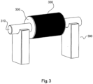
Fig. 2 bis 9 zeigen schematisch verschiedene Schritte bei der Herstellung eines Bauteils für eine Windenergieanlage. InFig. 2 ist eine Wickeleinheit 300 mit einer Welle 310 und einem Wickelkern 320 gezeigt. Durch Drehen der Welle 310 wird auch der Wickelkern rotiert. Wie inFig. 3 gezeigt, kann eine Vakuumfolie 330 um den Wickelkern 320 vorgesehen sein. Anschließend kann wie inFig. 4 gezeigt ein Fließgitteraufbau 340 um die Vakuumfolie 330 vorgesehen sein. - Ein Gelege wird um den Wickelkern 320 mit der Vakuumfolie 330 und dem Fließgitteraufbau 340 umwickelt, so dass ein herzustellendes Bauteil 350 gewickelt wird. Das Bauteil 350 kann ein erstes Ende 351 und ein zweites Ende 352 aufweisen, wobei das zweite Ende 352 zumindest teilweise kegelförmig ausgestaltet sein kann.
- Wie in
Fig. 6 zu sehen, wird eine Außenform 360 um den Wickelkern 320 und das gewickelte Bauteil 350 platziert. Da die Außenform mehrteilig ist, kann zunächst eine erste Halbschale der Außenform 360 platziert werden. Anschließend kann eine zweite Halbschale das restliche Bauteil 350 umgeben. - In
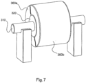
Fig. 7 ist gezeigt, dass die beiden Halbschalen, welche die Außenform ausbilden, um das Bauteil 350 herum platziert sind. Diese sind zueinander vakuumdicht verschlossen. Die Vakuumfolie 330 wird mit der Außenform vakuumdicht verschlossen und bildet damit den Infusionsraum, in welchen das Harz eingeführt werden kann. - Wie in
Fig. 8 und9 zu sehen, kann der Wickelkern 320 mit der Welle 310 komplett entfernt werden, so dass lediglich die Außenform 360 mit dem sich darin befindlichen Bauteil 350 übrig bleibt. - Wie in
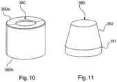
Fig. 10 zu sehen, kann die Außenform mit dem Bauteil entfernt werden und ein Vakuuminfusionsverfahren kann durchgeführt werden, um das Gelege des gewickelten Bauteils mit Harz zu infundieren. Anschließend kann das Harz ausgehärtet werden, so dass am Ende das fertige Bauteil 350 wie inFig. 11 zu sehen erhalten wird. - Wie in
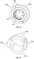
Fig. 12 zu sehen, kann die Außenform mindestens zweiteilig ausgestaltet sein. Optional kann die Außenform auch mehrteilig ausgestaltet sein. - Wie in
Fig. 13 zu sehen, kann das Bauteil 350 mehrteilig ausgestaltet sein, indem das gewickelte Bauteil in Einzelteile getrennt wird. - Gemäß der Erfindung wird somit eine Vakuumfolie 330 auf dem Wickelkern 320 platziert. Diese wird zur Außenform abgedichtet, die, wie oben beschrieben, in sich vakuumdicht ist. Eine weitere Vakuumfolie kann optional zwischen dem Bauteil und der Außenform vorgesehen sein, so dass ein Vakuum zwischen der Vakuumfolie und der Außenform erzeugt werden kann. Dies kann dazu führen, dass das gewickelte Gelege 350 sich nach außen entspannen Der Wickelkern 320 wird entfernt, bevor Harz mittels des Vakuuminfusionsverfahrens in das gewickelte Gelege eindiffundieren kann. Dies ist erfindungsgemäß vorteilhaft, weil damit eine wellen- und faltenfreie Außenkontur des Bauteils erhalten werden kann.
- Die Dicke des aufgewickelten Geleges ist typischerweise kleiner als der Abstand zwischen dem Wickelkern und der Innenseite der Außenform, so dass das Gelege gegen eine Innenwand der Außenform gepresst wird und es somit zu einem Spalt zwischen dem Gelege und der äußeren Wand des Wickelkerns 320 kommen kann. Somit wird das Gelege von innen nach außen gestrafft und der Wickelkern 320 kann auf einfache Art und Weise entfernt werden.
- Nachdem ein Vakuum zwischen der Vakuumfolie 330 und der Innenseite der Außenform 360 erzeugt worden ist, kann die Außenform 360 vom Wickelkern entfernt werden.
- Der Wickelkern 320 kann dann zwischenzeitlich wiederverwendet werden, um ein weiteres Bauteil 350 herzustellen.
- Entsprechend der Geometrie der zu wickelnden Form kann die Außenform 360 einteilig ausgestaltet sein. Alternativ dazu kann die Außenform mehrteilig ausgestaltet sein, so dass die Einzelteile der Außenform separat entfernt werden können.
- Mit dem erfindungsgemäßen Verfahren können beispielsweise Blattanschlussbereiche eines Windenergieanlagen-Rotorblattes durch Preform-Segmente hergestellt werden. Diese Preform-Segmente können gemäß der Erfindung hergestellt werden. Damit kann vermieden werden, dass die Bauteile Fehler in Form von Falten oder Stauchungen an der Außenkontur aufweisen. Dies wird erfindungsgemäß u. a. durch die Verwendung des Vakuuminfusionsverfahrens erreicht.
- Die Erfindung betrifft insbesondere eine Verwendung einer (mehrteiligen) positiven Außenform, um gewickelte Bauteile mit einer definierten Außengeometrie herzustellen.
- Das herzustellende Bauteil kann gemäß der Erfindung innere und äußere Flanschaufdickungen, Preform-Segmente und Innenrotorblätter darstellen. Alternativ dazu können Holmkästen mit dem erfindungsgemäßen Verfahren hergestellt werden.
- Das erfindungsgemäße Verfahren erlaubt eine effektive und fehlerfreie Herstellung von Rotorblattkomponenten. Insbesondere können Zuschnittkapazitäten und Bauteilformen eingespart werden. Des Weiteren kann die Passgenauigkeit der einzelnen Teile untereinander und zu angrenzenden Formen erheblich verbessert werden.
Claims (3)
- Verfahren zum Herstellen eines Bauteils einer Windenergieanlage, insbesondere eines Windenergieanlagen-Rotorblattes, mit den Schritten:Vorsehen eines Wickelkerns (320) auf einer drehbaren Welle (310),Platzieren einer Vakuumfolie (330) auf dem Wickelkern (320),Wickeln eines herzustellenden Bauteils (350) auf der Vakuumfolie (330) mittels eines Wickelgeleges,Platzieren einer Außenform (360) um das gewickelte Bauteil (350),Durchführen eines Vakuuminfusionsverfahrens,Aushärten des infundierten Harzes, undEntfernen des Wickelkerns (320), bevor das Vakuuminfusionsverfahren durchgeführt wird,wobei ein Vakuum zwischen der Vakuumfolie (330) auf dem Wickelkern (320) und einer Innenseite der Außenform (360) erzeugt wird, so dass das aufgewickelte Gelege gegen die Innenseite der Außenform (360) gepresst wird.
- Verfahren zum Herstellen eines Bauteils einer Windenergieanlage nach Anspruch 1, wobei
die Außenform (360) mehrteilig ausgestaltet ist. - Verfahren zum Herstellen eines Bauteils einer Windenergieanlage nach einem der Ansprüche 1 bis 2, ferner mit dem Schritt:
Trennen des fertigen Bauteils (350), um getrennte Einzelsegmente vorzusehen.
Applications Claiming Priority (2)
| Application Number | Priority Date | Filing Date | Title |
|---|---|---|---|
| DE102018100941.0A DE102018100941A1 (de) | 2018-01-17 | 2018-01-17 | Verfahren zum Herstellen von Komponenten einer Windenergieanlage, insbesondere eines Windenergieanlagen-Rotorblattes |
| PCT/EP2019/051106 WO2019141758A1 (de) | 2018-01-17 | 2019-01-17 | Verfahren zum herstellen von komponenten einer windenergieanlage, insbesondere eines windenergieanlagen-rotorblattes |
Publications (2)
| Publication Number | Publication Date |
|---|---|
| EP3740377A1 EP3740377A1 (de) | 2020-11-25 |
| EP3740377B1 true EP3740377B1 (de) | 2023-05-10 |
Family
ID=65036814
Family Applications (1)
| Application Number | Title | Priority Date | Filing Date |
|---|---|---|---|
| EP19700929.3A Active EP3740377B1 (de) | 2018-01-17 | 2019-01-17 | Verfahren zum herstellen von komponenten einer windenergieanlage, insbesondere eines windenergieanlagen-rotorblattes |
Country Status (5)
| Country | Link |
|---|---|
| US (1) | US20200346418A1 (de) |
| EP (1) | EP3740377B1 (de) |
| CN (1) | CN111615450A (de) |
| DE (1) | DE102018100941A1 (de) |
| WO (1) | WO2019141758A1 (de) |
Families Citing this family (3)
| Publication number | Priority date | Publication date | Assignee | Title |
|---|---|---|---|---|
| EP3822065B1 (de) * | 2019-11-14 | 2024-07-31 | Siemens Gamesa Renewable Energy A/S | Verfahren zur herstellung von wurzelsegmentelementen für ein wurzelsegment einer turbinenschaufel, verfahren zur herstellung des wurzelsegmentes und verfahren zur herstellung einer turbinenschaufel |
| DE102021116083B4 (de) | 2021-06-22 | 2023-09-21 | Dr. Ing. H.C. F. Porsche Aktiengesellschaft | Verfahren zur Herstellung einer Abdichteinrichtung für eine elektrische Maschine und Vorrichtung zur Durchführung |
| DE102021118608A1 (de) | 2021-07-19 | 2023-01-19 | Hawart Sondermaschinenbau Gmbh | Rotorblatt für eine Windkraftanlage sowie Verfahren und Vorrichtung zum Herstellen eines Flanscheinlegers für das Rotorblatt |
Family Cites Families (11)
| Publication number | Priority date | Publication date | Assignee | Title |
|---|---|---|---|---|
| CH617126A5 (en) | 1977-04-07 | 1980-05-14 | Micafil Ag | Process for producing hollow bodies, in particular pipes |
| JPS63173625A (ja) * | 1987-01-13 | 1988-07-18 | Nitto Boseki Co Ltd | 繊維強化樹脂筒の製造方法 |
| DE3716335A1 (de) * | 1987-05-15 | 1988-12-01 | Dornier Gmbh | Verfahren zur herstellung von geschlossenen formkoerpern |
| JPH06336B2 (ja) * | 1989-02-09 | 1994-01-05 | 日東紡績株式会社 | 繊維強化プラスチック成形用プリフォーム及びその製造方法 |
| FR2831479B1 (fr) * | 2001-10-26 | 2004-01-02 | Coriolis Composites | Procede de fabrication de profils presentant un etat de surface specifique en resines synthetiques renforcees par des fibres et machine pour mettre en oeuvre le procede |
| DE10304044A1 (de) * | 2003-01-29 | 2004-08-05 | Funck, Ralph, Dr. | Verfahren zur Herstellung von Rohren |
| EP2361752B1 (de) * | 2010-02-24 | 2015-04-08 | BARD Holding GmbH | Faserverbundbauteil und Verfahren zur Herstellung desselben |
| DE102010026018A1 (de) * | 2010-07-03 | 2012-03-08 | H. Bloeß - H.-J. Bloeß GbR (vertretungsberechtigter Gesellschafter Herr Heye Bloeß, Birkenweg 1, 26789 Leer) | Rotorblatt für Windenergieanlagen in Wickeltechnik und unter Infusionsverfahren sowie Verfahren zu dessen Herstellung |
| PL3155159T3 (pl) * | 2014-06-16 | 2018-10-31 | Lm Wind Power International Technology Ii Aps | Sposób produkowania ciągłej warstwy wzmacniającej z włókien z oddzielnych mat z włókien |
| DE102015204490A1 (de) * | 2015-03-12 | 2016-09-15 | Wobben Properties Gmbh | Verfahren und Vorrichtung zum Herstellen eines Vorformlings |
| DE102016110848A1 (de) * | 2016-06-14 | 2017-12-14 | Wobben Properties Gmbh | Verfahren und Vorrichtung zum Herstellen eines Vorformlings |
-
2018
- 2018-01-17 DE DE102018100941.0A patent/DE102018100941A1/de not_active Withdrawn
-
2019
- 2019-01-17 US US16/960,838 patent/US20200346418A1/en not_active Abandoned
- 2019-01-17 CN CN201980008565.5A patent/CN111615450A/zh active Pending
- 2019-01-17 WO PCT/EP2019/051106 patent/WO2019141758A1/de not_active Ceased
- 2019-01-17 EP EP19700929.3A patent/EP3740377B1/de active Active
Also Published As
| Publication number | Publication date |
|---|---|
| EP3740377A1 (de) | 2020-11-25 |
| US20200346418A1 (en) | 2020-11-05 |
| WO2019141758A1 (de) | 2019-07-25 |
| CN111615450A (zh) | 2020-09-01 |
| DE102018100941A1 (de) | 2019-07-18 |
Similar Documents
| Publication | Publication Date | Title |
|---|---|---|
| DE102007020338B4 (de) | Verfahren zum Herstellen von Blättern | |
| DE102008044530A1 (de) | Gießformen für Windkraftanlagen-Rotorflügel | |
| DE102009003421A1 (de) | Rotorflügel einer Windkraftanlage und Verfahren zur Herstellung desselben | |
| DE102006052690A1 (de) | Verfahren zur Herstellung von Rotorblättern einer Windenergieanlage | |
| DE102011056342A1 (de) | Verfahren zur Herstellung von Rotorflügeln für eine Windkraftanlage | |
| EP2561977B1 (de) | Verfahren zur Herstellung eines Windenergieanlagenrotorblattteils mit einem kohlenstofffaserverstärkten Hauptgurt | |
| EP3740377A1 (de) | Verfahren zum herstellen von komponenten einer windenergieanlage, insbesondere eines windenergieanlagen-rotorblattes | |
| EP2925510B1 (de) | Verfahren zur bearbeitung eines faserkunststoffverbundes eines rotorblattes, halbzeug in form eines aufbauverbundes und uv-lampe zum aushärten eines uv-aushärtbaren matrixmaterials | |
| DE102015212452A1 (de) | Trägerelement, insbesondere Statorträger-Element und/oder Läuferträger-Element, System von Trägerelementen, Generatorträger, Generator, Generator-Tragsystem, Gondel einer Windenergieanlage, Windenergieanlage und Verfahren zur Montage eines Generator-Tragsystems | |
| WO2009112017A2 (de) | Verfahren zur herstellung eines rotorblattes für eine windkraftanlage sowie ein nach diesem verfahren hergestelltes rotorblatt | |
| WO2017001345A1 (de) | Trägerelement, insbesondere statorträger-element und/oder läuferträger-element, system von trägerelementen, generatorträger, generator, generator-tragsystem, gondel einer windenergieanlage, windenergieanlage und verfahren zur montage eines generator-tragsystems | |
| EP3634730B1 (de) | Verfahren zum herstellen eines windenergieanlagen-rotorblattes | |
| EP3268197B1 (de) | Verfahren zum herstellen eines vorformlings | |
| EP2934865B1 (de) | Vorrichtung und verfahren zur infiltration einer faserpreform | |
| WO2014177363A2 (de) | Synchrongenerator-stator und synchrongenerator | |
| EP3564523B1 (de) | Flanschanschluss für ein windenergieanlagenrotorblatt, versteifungslage für einen flanschanschluss, flanscheinleger, windenergieanlagenrotorblatt, windenergieanlage sowie verfahren zum herstellen eines flanschanschlusses | |
| DE2038112A1 (de) | Verfahren und Vorrichtung zur Herstellung eines Giessharzrohres mit Glasfaserverstaerkung im Schleudergiessverfahren | |
| EP0602631A1 (de) | Verfahren zur Herstellung eines Leitgitters für Turbomaschinen, insbesondere für Axialverdichter | |
| EP3362679B1 (de) | Windenergieanlagen-rotorblatt und verfahren zum herstellen eines windenergieanlagen-rotorblattes | |
| DE102009010613A1 (de) | Verfahren zum Anbringen bzw. Herstellen eines geschlossenen Deckbandes für eine Laufbeschaufelung einer Turbinenstufe sowie Laufbeschaufelung einer Turbinenstufe für eine Turbine | |
| DE10205657C2 (de) | Verfahren zur Herstellung einer rohrförmigen, torsions-und biegesteifen Antriebswelle | |
| WO2017001503A1 (de) | Verfahren zum herstellen eines windenergieanlagen-rotorblattes und windenergieanlagen-rotorblatt | |
| EP3841298B1 (de) | Windenergieanlagen-rotorblatt | |
| EP3653872A1 (de) | Verfahren zum herstellen zweier rotorblattsegmente, rotorblattsegment sowie geteiltes rotorblatt | |
| WO2018015098A1 (de) | Windenergieanlagen-rotorblatt und windenergieanlagen-rotorblattspitze |
Legal Events
| Date | Code | Title | Description |
|---|---|---|---|
| STAA | Information on the status of an ep patent application or granted ep patent |
Free format text: STATUS: UNKNOWN |
|
| STAA | Information on the status of an ep patent application or granted ep patent |
Free format text: STATUS: THE INTERNATIONAL PUBLICATION HAS BEEN MADE |
|
| PUAI | Public reference made under article 153(3) epc to a published international application that has entered the european phase |
Free format text: ORIGINAL CODE: 0009012 |
|
| STAA | Information on the status of an ep patent application or granted ep patent |
Free format text: STATUS: REQUEST FOR EXAMINATION WAS MADE |
|
| 17P | Request for examination filed |
Effective date: 20200817 |
|
| AK | Designated contracting states |
Kind code of ref document: A1 Designated state(s): AL AT BE BG CH CY CZ DE DK EE ES FI FR GB GR HR HU IE IS IT LI LT LU LV MC MK MT NL NO PL PT RO RS SE SI SK SM TR |
|
| AX | Request for extension of the european patent |
Extension state: BA ME |
|
| DAV | Request for validation of the european patent (deleted) | ||
| DAX | Request for extension of the european patent (deleted) | ||
| GRAP | Despatch of communication of intention to grant a patent |
Free format text: ORIGINAL CODE: EPIDOSNIGR1 |
|
| STAA | Information on the status of an ep patent application or granted ep patent |
Free format text: STATUS: GRANT OF PATENT IS INTENDED |
|
| RIC1 | Information provided on ipc code assigned before grant |
Ipc: F03D 1/06 20060101ALN20221208BHEP Ipc: B29L 31/08 20060101ALI20221208BHEP Ipc: B29C 70/32 20060101ALI20221208BHEP Ipc: B29C 70/44 20060101AFI20221208BHEP |
|
| INTG | Intention to grant announced |
Effective date: 20230110 |
|
| GRAS | Grant fee paid |
Free format text: ORIGINAL CODE: EPIDOSNIGR3 |
|
| GRAA | (expected) grant |
Free format text: ORIGINAL CODE: 0009210 |
|
| STAA | Information on the status of an ep patent application or granted ep patent |
Free format text: STATUS: THE PATENT HAS BEEN GRANTED |
|
| AK | Designated contracting states |
Kind code of ref document: B1 Designated state(s): AL AT BE BG CH CY CZ DE DK EE ES FI FR GB GR HR HU IE IS IT LI LT LU LV MC MK MT NL NO PL PT RO RS SE SI SK SM TR |
|
| REG | Reference to a national code |
Ref country code: GB Ref legal event code: FG4D Free format text: NOT ENGLISH |
|
| REG | Reference to a national code |
Ref country code: AT Ref legal event code: REF Ref document number: 1566288 Country of ref document: AT Kind code of ref document: T Effective date: 20230515 Ref country code: CH Ref legal event code: EP |
|
| REG | Reference to a national code |
Ref country code: DE Ref legal event code: R096 Ref document number: 502019007682 Country of ref document: DE |
|
| REG | Reference to a national code |
Ref country code: IE Ref legal event code: FG4D Free format text: LANGUAGE OF EP DOCUMENT: GERMAN |
|
| REG | Reference to a national code |
Ref country code: LT Ref legal event code: MG9D |
|
| REG | Reference to a national code |
Ref country code: NL Ref legal event code: MP Effective date: 20230510 |
|
| PG25 | Lapsed in a contracting state [announced via postgrant information from national office to epo] |
Ref country code: SE Free format text: LAPSE BECAUSE OF FAILURE TO SUBMIT A TRANSLATION OF THE DESCRIPTION OR TO PAY THE FEE WITHIN THE PRESCRIBED TIME-LIMIT Effective date: 20230510 Ref country code: PT Free format text: LAPSE BECAUSE OF FAILURE TO SUBMIT A TRANSLATION OF THE DESCRIPTION OR TO PAY THE FEE WITHIN THE PRESCRIBED TIME-LIMIT Effective date: 20230911 Ref country code: NO Free format text: LAPSE BECAUSE OF FAILURE TO SUBMIT A TRANSLATION OF THE DESCRIPTION OR TO PAY THE FEE WITHIN THE PRESCRIBED TIME-LIMIT Effective date: 20230810 Ref country code: NL Free format text: LAPSE BECAUSE OF FAILURE TO SUBMIT A TRANSLATION OF THE DESCRIPTION OR TO PAY THE FEE WITHIN THE PRESCRIBED TIME-LIMIT Effective date: 20230510 Ref country code: ES Free format text: LAPSE BECAUSE OF FAILURE TO SUBMIT A TRANSLATION OF THE DESCRIPTION OR TO PAY THE FEE WITHIN THE PRESCRIBED TIME-LIMIT Effective date: 20230510 |
|
| PG25 | Lapsed in a contracting state [announced via postgrant information from national office to epo] |
Ref country code: RS Free format text: LAPSE BECAUSE OF FAILURE TO SUBMIT A TRANSLATION OF THE DESCRIPTION OR TO PAY THE FEE WITHIN THE PRESCRIBED TIME-LIMIT Effective date: 20230510 Ref country code: PL Free format text: LAPSE BECAUSE OF FAILURE TO SUBMIT A TRANSLATION OF THE DESCRIPTION OR TO PAY THE FEE WITHIN THE PRESCRIBED TIME-LIMIT Effective date: 20230510 Ref country code: LV Free format text: LAPSE BECAUSE OF FAILURE TO SUBMIT A TRANSLATION OF THE DESCRIPTION OR TO PAY THE FEE WITHIN THE PRESCRIBED TIME-LIMIT Effective date: 20230510 Ref country code: LT Free format text: LAPSE BECAUSE OF FAILURE TO SUBMIT A TRANSLATION OF THE DESCRIPTION OR TO PAY THE FEE WITHIN THE PRESCRIBED TIME-LIMIT Effective date: 20230510 Ref country code: IS Free format text: LAPSE BECAUSE OF FAILURE TO SUBMIT A TRANSLATION OF THE DESCRIPTION OR TO PAY THE FEE WITHIN THE PRESCRIBED TIME-LIMIT Effective date: 20230910 Ref country code: HR Free format text: LAPSE BECAUSE OF FAILURE TO SUBMIT A TRANSLATION OF THE DESCRIPTION OR TO PAY THE FEE WITHIN THE PRESCRIBED TIME-LIMIT Effective date: 20230510 Ref country code: GR Free format text: LAPSE BECAUSE OF FAILURE TO SUBMIT A TRANSLATION OF THE DESCRIPTION OR TO PAY THE FEE WITHIN THE PRESCRIBED TIME-LIMIT Effective date: 20230811 |
|
| PG25 | Lapsed in a contracting state [announced via postgrant information from national office to epo] |
Ref country code: FI Free format text: LAPSE BECAUSE OF FAILURE TO SUBMIT A TRANSLATION OF THE DESCRIPTION OR TO PAY THE FEE WITHIN THE PRESCRIBED TIME-LIMIT Effective date: 20230510 |
|
| PG25 | Lapsed in a contracting state [announced via postgrant information from national office to epo] |
Ref country code: SK Free format text: LAPSE BECAUSE OF FAILURE TO SUBMIT A TRANSLATION OF THE DESCRIPTION OR TO PAY THE FEE WITHIN THE PRESCRIBED TIME-LIMIT Effective date: 20230510 |
|
| PG25 | Lapsed in a contracting state [announced via postgrant information from national office to epo] |
Ref country code: SM Free format text: LAPSE BECAUSE OF FAILURE TO SUBMIT A TRANSLATION OF THE DESCRIPTION OR TO PAY THE FEE WITHIN THE PRESCRIBED TIME-LIMIT Effective date: 20230510 Ref country code: SK Free format text: LAPSE BECAUSE OF FAILURE TO SUBMIT A TRANSLATION OF THE DESCRIPTION OR TO PAY THE FEE WITHIN THE PRESCRIBED TIME-LIMIT Effective date: 20230510 Ref country code: RO Free format text: LAPSE BECAUSE OF FAILURE TO SUBMIT A TRANSLATION OF THE DESCRIPTION OR TO PAY THE FEE WITHIN THE PRESCRIBED TIME-LIMIT Effective date: 20230510 Ref country code: EE Free format text: LAPSE BECAUSE OF FAILURE TO SUBMIT A TRANSLATION OF THE DESCRIPTION OR TO PAY THE FEE WITHIN THE PRESCRIBED TIME-LIMIT Effective date: 20230510 Ref country code: DK Free format text: LAPSE BECAUSE OF FAILURE TO SUBMIT A TRANSLATION OF THE DESCRIPTION OR TO PAY THE FEE WITHIN THE PRESCRIBED TIME-LIMIT Effective date: 20230510 Ref country code: CZ Free format text: LAPSE BECAUSE OF FAILURE TO SUBMIT A TRANSLATION OF THE DESCRIPTION OR TO PAY THE FEE WITHIN THE PRESCRIBED TIME-LIMIT Effective date: 20230510 |
|
| REG | Reference to a national code |
Ref country code: DE Ref legal event code: R097 Ref document number: 502019007682 Country of ref document: DE |
|
| PLBE | No opposition filed within time limit |
Free format text: ORIGINAL CODE: 0009261 |
|
| STAA | Information on the status of an ep patent application or granted ep patent |
Free format text: STATUS: NO OPPOSITION FILED WITHIN TIME LIMIT |
|
| 26N | No opposition filed |
Effective date: 20240213 |
|
| PG25 | Lapsed in a contracting state [announced via postgrant information from national office to epo] |
Ref country code: SI Free format text: LAPSE BECAUSE OF FAILURE TO SUBMIT A TRANSLATION OF THE DESCRIPTION OR TO PAY THE FEE WITHIN THE PRESCRIBED TIME-LIMIT Effective date: 20230510 |
|
| PG25 | Lapsed in a contracting state [announced via postgrant information from national office to epo] |
Ref country code: SI Free format text: LAPSE BECAUSE OF FAILURE TO SUBMIT A TRANSLATION OF THE DESCRIPTION OR TO PAY THE FEE WITHIN THE PRESCRIBED TIME-LIMIT Effective date: 20230510 Ref country code: IT Free format text: LAPSE BECAUSE OF FAILURE TO SUBMIT A TRANSLATION OF THE DESCRIPTION OR TO PAY THE FEE WITHIN THE PRESCRIBED TIME-LIMIT Effective date: 20230510 |
|
| PG25 | Lapsed in a contracting state [announced via postgrant information from national office to epo] |
Ref country code: MC Free format text: LAPSE BECAUSE OF FAILURE TO SUBMIT A TRANSLATION OF THE DESCRIPTION OR TO PAY THE FEE WITHIN THE PRESCRIBED TIME-LIMIT Effective date: 20230510 |
|
| PG25 | Lapsed in a contracting state [announced via postgrant information from national office to epo] |
Ref country code: MC Free format text: LAPSE BECAUSE OF FAILURE TO SUBMIT A TRANSLATION OF THE DESCRIPTION OR TO PAY THE FEE WITHIN THE PRESCRIBED TIME-LIMIT Effective date: 20230510 |
|
| REG | Reference to a national code |
Ref country code: CH Ref legal event code: PL |
|
| PG25 | Lapsed in a contracting state [announced via postgrant information from national office to epo] |
Ref country code: LU Free format text: LAPSE BECAUSE OF NON-PAYMENT OF DUE FEES Effective date: 20240117 |
|
| PG25 | Lapsed in a contracting state [announced via postgrant information from national office to epo] |
Ref country code: LU Free format text: LAPSE BECAUSE OF NON-PAYMENT OF DUE FEES Effective date: 20240117 |
|
| PG25 | Lapsed in a contracting state [announced via postgrant information from national office to epo] |
Ref country code: BE Free format text: LAPSE BECAUSE OF NON-PAYMENT OF DUE FEES Effective date: 20240131 |
|
| PG25 | Lapsed in a contracting state [announced via postgrant information from national office to epo] |
Ref country code: CH Free format text: LAPSE BECAUSE OF NON-PAYMENT OF DUE FEES Effective date: 20240131 |
|
| PG25 | Lapsed in a contracting state [announced via postgrant information from national office to epo] |
Ref country code: CH Free format text: LAPSE BECAUSE OF NON-PAYMENT OF DUE FEES Effective date: 20240131 Ref country code: BE Free format text: LAPSE BECAUSE OF NON-PAYMENT OF DUE FEES Effective date: 20240131 |
|
| REG | Reference to a national code |
Ref country code: BE Ref legal event code: MM Effective date: 20240131 |
|
| PG25 | Lapsed in a contracting state [announced via postgrant information from national office to epo] |
Ref country code: BG Free format text: LAPSE BECAUSE OF FAILURE TO SUBMIT A TRANSLATION OF THE DESCRIPTION OR TO PAY THE FEE WITHIN THE PRESCRIBED TIME-LIMIT Effective date: 20230510 |
|
| PG25 | Lapsed in a contracting state [announced via postgrant information from national office to epo] |
Ref country code: BG Free format text: LAPSE BECAUSE OF FAILURE TO SUBMIT A TRANSLATION OF THE DESCRIPTION OR TO PAY THE FEE WITHIN THE PRESCRIBED TIME-LIMIT Effective date: 20230510 |
|
| PG25 | Lapsed in a contracting state [announced via postgrant information from national office to epo] |
Ref country code: IE Free format text: LAPSE BECAUSE OF NON-PAYMENT OF DUE FEES Effective date: 20240117 |
|
| PG25 | Lapsed in a contracting state [announced via postgrant information from national office to epo] |
Ref country code: IE Free format text: LAPSE BECAUSE OF NON-PAYMENT OF DUE FEES Effective date: 20240117 |
|
| REG | Reference to a national code |
Ref country code: AT Ref legal event code: MM01 Ref document number: 1566288 Country of ref document: AT Kind code of ref document: T Effective date: 20240117 |
|
| PG25 | Lapsed in a contracting state [announced via postgrant information from national office to epo] |
Ref country code: AT Free format text: LAPSE BECAUSE OF NON-PAYMENT OF DUE FEES Effective date: 20240117 |
|
| PGFP | Annual fee paid to national office [announced via postgrant information from national office to epo] |
Ref country code: FR Payment date: 20250123 Year of fee payment: 7 |
|
| PGFP | Annual fee paid to national office [announced via postgrant information from national office to epo] |
Ref country code: GB Payment date: 20250123 Year of fee payment: 7 |
|
| PG25 | Lapsed in a contracting state [announced via postgrant information from national office to epo] |
Ref country code: CY Free format text: LAPSE BECAUSE OF FAILURE TO SUBMIT A TRANSLATION OF THE DESCRIPTION OR TO PAY THE FEE WITHIN THE PRESCRIBED TIME-LIMIT; INVALID AB INITIO Effective date: 20190117 |
|
| PG25 | Lapsed in a contracting state [announced via postgrant information from national office to epo] |
Ref country code: HU Free format text: LAPSE BECAUSE OF FAILURE TO SUBMIT A TRANSLATION OF THE DESCRIPTION OR TO PAY THE FEE WITHIN THE PRESCRIBED TIME-LIMIT; INVALID AB INITIO Effective date: 20190117 |
|
| PG25 | Lapsed in a contracting state [announced via postgrant information from national office to epo] |
Ref country code: TR Free format text: LAPSE BECAUSE OF FAILURE TO SUBMIT A TRANSLATION OF THE DESCRIPTION OR TO PAY THE FEE WITHIN THE PRESCRIBED TIME-LIMIT Effective date: 20230510 |
|
| PGFP | Annual fee paid to national office [announced via postgrant information from national office to epo] |
Ref country code: DE Payment date: 20260204 Year of fee payment: 8 |