EP2361752A1 - Faserverbundbauteil und Verfahren zur Herstellung desselben - Google Patents
Faserverbundbauteil und Verfahren zur Herstellung desselben Download PDFInfo
- Publication number
- EP2361752A1 EP2361752A1 EP10001871A EP10001871A EP2361752A1 EP 2361752 A1 EP2361752 A1 EP 2361752A1 EP 10001871 A EP10001871 A EP 10001871A EP 10001871 A EP10001871 A EP 10001871A EP 2361752 A1 EP2361752 A1 EP 2361752A1
- Authority
- EP
- European Patent Office
- Prior art keywords
- fiber
- fiber material
- material layer
- composite component
- longitudinal direction
- Prior art date
- Legal status (The legal status is an assumption and is not a legal conclusion. Google has not performed a legal analysis and makes no representation as to the accuracy of the status listed.)
- Granted
Links
Images



Classifications
-
- B—PERFORMING OPERATIONS; TRANSPORTING
- B29—WORKING OF PLASTICS; WORKING OF SUBSTANCES IN A PLASTIC STATE IN GENERAL
- B29C—SHAPING OR JOINING OF PLASTICS; SHAPING OF MATERIAL IN A PLASTIC STATE, NOT OTHERWISE PROVIDED FOR; AFTER-TREATMENT OF THE SHAPED PRODUCTS, e.g. REPAIRING
- B29C70/00—Shaping composites, i.e. plastics material comprising reinforcements, fillers or preformed parts, e.g. inserts
- B29C70/04—Shaping composites, i.e. plastics material comprising reinforcements, fillers or preformed parts, e.g. inserts comprising reinforcements only, e.g. self-reinforcing plastics
- B29C70/06—Fibrous reinforcements only
- B29C70/08—Fibrous reinforcements only comprising combinations of different forms of fibrous reinforcements incorporated in matrix material, forming one or more layers, and with or without non-reinforced layers
- B29C70/083—Combinations of continuous fibres or fibrous profiled structures oriented in one direction and reinforcements forming a two dimensional structure, e.g. mats
-
- B—PERFORMING OPERATIONS; TRANSPORTING
- B29—WORKING OF PLASTICS; WORKING OF SUBSTANCES IN A PLASTIC STATE IN GENERAL
- B29C—SHAPING OR JOINING OF PLASTICS; SHAPING OF MATERIAL IN A PLASTIC STATE, NOT OTHERWISE PROVIDED FOR; AFTER-TREATMENT OF THE SHAPED PRODUCTS, e.g. REPAIRING
- B29C53/00—Shaping by bending, folding, twisting, straightening or flattening; Apparatus therefor
- B29C53/56—Winding and joining, e.g. winding spirally
- B29C53/58—Winding and joining, e.g. winding spirally helically
- B29C53/581—Winding and joining, e.g. winding spirally helically using sheets or strips consisting principally of plastics material
- B29C53/582—Winding and joining, e.g. winding spirally helically using sheets or strips consisting principally of plastics material comprising reinforcements, e.g. wires, threads
-
- B—PERFORMING OPERATIONS; TRANSPORTING
- B29—WORKING OF PLASTICS; WORKING OF SUBSTANCES IN A PLASTIC STATE IN GENERAL
- B29C—SHAPING OR JOINING OF PLASTICS; SHAPING OF MATERIAL IN A PLASTIC STATE, NOT OTHERWISE PROVIDED FOR; AFTER-TREATMENT OF THE SHAPED PRODUCTS, e.g. REPAIRING
- B29C70/00—Shaping composites, i.e. plastics material comprising reinforcements, fillers or preformed parts, e.g. inserts
- B29C70/04—Shaping composites, i.e. plastics material comprising reinforcements, fillers or preformed parts, e.g. inserts comprising reinforcements only, e.g. self-reinforcing plastics
- B29C70/06—Fibrous reinforcements only
- B29C70/10—Fibrous reinforcements only characterised by the structure of fibrous reinforcements, e.g. hollow fibres
- B29C70/16—Fibrous reinforcements only characterised by the structure of fibrous reinforcements, e.g. hollow fibres using fibres of substantial or continuous length
- B29C70/22—Fibrous reinforcements only characterised by the structure of fibrous reinforcements, e.g. hollow fibres using fibres of substantial or continuous length oriented in at least two directions forming a two-dimensional [2D] structure
-
- B—PERFORMING OPERATIONS; TRANSPORTING
- B29—WORKING OF PLASTICS; WORKING OF SUBSTANCES IN A PLASTIC STATE IN GENERAL
- B29C—SHAPING OR JOINING OF PLASTICS; SHAPING OF MATERIAL IN A PLASTIC STATE, NOT OTHERWISE PROVIDED FOR; AFTER-TREATMENT OF THE SHAPED PRODUCTS, e.g. REPAIRING
- B29C70/00—Shaping composites, i.e. plastics material comprising reinforcements, fillers or preformed parts, e.g. inserts
- B29C70/04—Shaping composites, i.e. plastics material comprising reinforcements, fillers or preformed parts, e.g. inserts comprising reinforcements only, e.g. self-reinforcing plastics
- B29C70/28—Shaping operations therefor
- B29C70/30—Shaping by lay-up, i.e. applying fibres, tape or broadsheet on a mould, former or core; Shaping by spray-up, i.e. spraying of fibres on a mould, former or core
- B29C70/32—Shaping by lay-up, i.e. applying fibres, tape or broadsheet on a mould, former or core; Shaping by spray-up, i.e. spraying of fibres on a mould, former or core on a rotating mould, former or core
-
- F—MECHANICAL ENGINEERING; LIGHTING; HEATING; WEAPONS; BLASTING
- F03—MACHINES OR ENGINES FOR LIQUIDS; WIND, SPRING, OR WEIGHT MOTORS; PRODUCING MECHANICAL POWER OR A REACTIVE PROPULSIVE THRUST, NOT OTHERWISE PROVIDED FOR
- F03D—WIND MOTORS
- F03D1/00—Wind motors with rotation axis substantially parallel to the air flow entering the rotor
- F03D1/06—Rotors
- F03D1/065—Rotors characterised by their construction elements
-
- B—PERFORMING OPERATIONS; TRANSPORTING
- B29—WORKING OF PLASTICS; WORKING OF SUBSTANCES IN A PLASTIC STATE IN GENERAL
- B29C—SHAPING OR JOINING OF PLASTICS; SHAPING OF MATERIAL IN A PLASTIC STATE, NOT OTHERWISE PROVIDED FOR; AFTER-TREATMENT OF THE SHAPED PRODUCTS, e.g. REPAIRING
- B29C53/00—Shaping by bending, folding, twisting, straightening or flattening; Apparatus therefor
- B29C53/56—Winding and joining, e.g. winding spirally
- B29C53/58—Winding and joining, e.g. winding spirally helically
- B29C53/60—Winding and joining, e.g. winding spirally helically using internal forming surfaces, e.g. mandrels
-
- B—PERFORMING OPERATIONS; TRANSPORTING
- B29—WORKING OF PLASTICS; WORKING OF SUBSTANCES IN A PLASTIC STATE IN GENERAL
- B29L—INDEXING SCHEME ASSOCIATED WITH SUBCLASS B29C, RELATING TO PARTICULAR ARTICLES
- B29L2031/00—Other particular articles
- B29L2031/08—Blades for rotors, stators, fans, turbines or the like, e.g. screw propellers
- B29L2031/082—Blades, e.g. for helicopters
-
- Y—GENERAL TAGGING OF NEW TECHNOLOGICAL DEVELOPMENTS; GENERAL TAGGING OF CROSS-SECTIONAL TECHNOLOGIES SPANNING OVER SEVERAL SECTIONS OF THE IPC; TECHNICAL SUBJECTS COVERED BY FORMER USPC CROSS-REFERENCE ART COLLECTIONS [XRACs] AND DIGESTS
- Y02—TECHNOLOGIES OR APPLICATIONS FOR MITIGATION OR ADAPTATION AGAINST CLIMATE CHANGE
- Y02E—REDUCTION OF GREENHOUSE GAS [GHG] EMISSIONS, RELATED TO ENERGY GENERATION, TRANSMISSION OR DISTRIBUTION
- Y02E10/00—Energy generation through renewable energy sources
- Y02E10/70—Wind energy
- Y02E10/72—Wind turbines with rotation axis in wind direction
-
- Y—GENERAL TAGGING OF NEW TECHNOLOGICAL DEVELOPMENTS; GENERAL TAGGING OF CROSS-SECTIONAL TECHNOLOGIES SPANNING OVER SEVERAL SECTIONS OF THE IPC; TECHNICAL SUBJECTS COVERED BY FORMER USPC CROSS-REFERENCE ART COLLECTIONS [XRACs] AND DIGESTS
- Y02—TECHNOLOGIES OR APPLICATIONS FOR MITIGATION OR ADAPTATION AGAINST CLIMATE CHANGE
- Y02P—CLIMATE CHANGE MITIGATION TECHNOLOGIES IN THE PRODUCTION OR PROCESSING OF GOODS
- Y02P70/00—Climate change mitigation technologies in the production process for final industrial or consumer products
- Y02P70/50—Manufacturing or production processes characterised by the final manufactured product
Definitions
- the present invention relates to a fiber composite member made of wound resin impregnated fiber material and a method for producing the same.
- this object is achieved by a fiber composite component of wound Kunststoffharzgetränktem fiber material, wherein the fiber material is arranged in at least two superimposed fiber layers and in the following first fiber material layer, the fiber material is a fiber fabric, a fiber fabric or a fiber mat and is wound so that the layer thickness in the circumferential direction of the fiber composite component is at least almost constant and varies in the longitudinal direction of the fiber composite component, and in the subsequent lying or underlying, hereinafter second said fiber material layer, the fiber material is a roving and is wound so that their layer thickness in the circumferential and longitudinal direction of the fiber composite component at least almost is constant.
- the two fiber material layers do not have to be the bottom two layers. If necessary, it can be provided for another location, if necessary.
- this object is achieved by a method for producing a fiber composite component from wound Kunststoffharzgetränktem fiber material, in particular according to one of the preceding claims, comprising the steps of: winding a fiber material, a Fasergelege, a fiber fabric or a fiber mat is, in a first fiber material layer on a form wound body such that the layer thickness of the first fiber material layer in the circumferential direction of the fiber composite component is at least approximately constant and varies in the longitudinal direction of the fiber composite component, and winding a fiber material, which is a roving in a second fiber material layer on the first fiber material layer such that the layer thickness of the second fiber material layer in the circumferential and longitudinal direction of the fiber composite component is at least approximately constant, or reverse arrangement of the first and second fiber material layers.
- the fiber material of the first fiber material layer is favorably oriented at an angle in the range of 0 ° to about 10 ° to the longitudinal direction of the fiber composite component.
- This layer is wound with a slight pitch, preferably overlapping.
- the fiber material of the second fiber material layer may be wound in a cross shape at an angle of approximately ⁇ 45 ° or approximately ⁇ 90 ° to the longitudinal direction of the fiber composite component. These are preferred values for the angle. Basically, the angle can take any value.
- a third fiber material layer rests on the first or second fiber material layer in which fiber material is obtained and wound analogously to that of the first fiber material layer. Analog should not necessarily mean that the fiber material of the third fiber material layer is identical and wound.
- a local reinforcement for load distribution is applied to the first, second or third fiber material layer in at least one region.
- the reinforcement is a reinforcing band, which preferably consists of fibers in its longitudinal direction.
- At least one further fiber material layer rests on the first, second or third fiber material layer with at least one local reinforcement applied thereto, in which the fiber material is obtained and wound analogously to that of the second fiber material layer.
- the fiber material of the further fiber material layer or the fiber materials of the further fiber material layers are identically constructed and wound.
- the fiber composite component is a blade connection for a rotor blade of a wind energy plant.
- the fiber material of the first fiber material layer is preferably wound at an angle in the range of 0 ° to about 10 ° to the longitudinal direction of the fiber composite component, preferably overlapping.
- the fiber material of the second fiber material layer is wound in a cross shape at an angle of approximately ⁇ 45 ° or approximately ⁇ 90 ° to the longitudinal direction of the fiber composite component.
- the angle can take any value.
- the method further comprises: winding a fiber material, which is a fiber fabric, a fiber fabric or a fiber mat, in a third fiber material layer on the first or second fiber material layer such that the layer thickness of the third fiber material layer in the circumferential direction of the fiber composite component at least almost is constant and varies in the longitudinal direction of the fiber composite component.
- a local reinforcement for load distribution is applied to the first or second fiber material layer in at least one region, wherein the reinforcement is preferably a reinforcing band, which preferably consists of fibers in its longitudinal direction.
- a local reinforcement for load distribution is applied to the third fiber material layer in at least one region, the reinforcement preferably being a reinforcement band, which preferably consists of fibers in its longitudinal direction.
- a further particular embodiment of the invention of the method further comprises: winding at least one further fibrous material layer on the first or second fibrous material layer with at least one local reinforcement applied thereto, wherein the fibrous material is a roving and is wound in such a way that the layer thickness of the fibrous material layer in circumferential and Longitudinal direction of the fiber composite component is at least almost constant.
- Yet another particular embodiment of the method further comprises: winding at least one further fibrous material layer on the third fibrous material layer with at least one local reinforcement applied thereto, wherein the fibrous material is a roving and is wound such that the layer thickness of the fibrous material layer in the circumferential and longitudinal directions of the fibrous material layer Fiber composite component is at least almost constant.
- the fiber composite component is preferably a blade connection for a rotor blade of a wind energy plant.
- the invention is based on the surprising finding that the production of a fiber composite component with a stiffness and material distribution adapted in the circumferential and longitudinal direction of the fiber composite component is possible by means of a special winding method.
- this makes it possible to produce a fiber composite component by means of a winding process, which on one side forms a preferably rotationally symmetrical connection region (bearing or flange in which the load introduction is distributed over the circumference), wherein the connection region is created by subsequent processing, such as drilling, etc.
- the region with concentrated force introduction regions can be designed rotationally symmetrically or to the requirements of an adjoining component, for example elliptically or approximately to a profile shape or parts thereof.
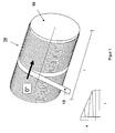
- FIG. 1 shows the winding of a shaped winding body or mold core 10 with a fiber material, in this case a resin-impregnated sliver 12.
- a fiber material in this case a resin-impregnated sliver 12.
- the sliver consists of a proportion of fibers in the band longitudinal direction and a further proportion almost transversely to the sliver direction.
- the fiber content per direction is based on the stiffness and strength requirements of the fiber composite component 14.
- the sliver 12 is at low pitch, that is at an angle in the range of 0 ° to 10 ° to the direction indicated by an arrow longitudinal direction of the fiber composite component on the Formwickel Sciences 10th wound, with the slivers overlap.
- the power transmission from one sliver 12 to the other is interlaminar via the resin-fiber composite.
- any continuous bandgap can be generated.
- the form wound body 10 will thus have approximately the same occupancy in the circumferential direction, but can be adjusted in the longitudinal direction.
- a first fiber material layer results whose layer thickness in the circumferential direction of the fiber composite component 14 is at least approximately constant and varies in the longitudinal direction of the fiber composite component 14.
- FIG. 1 the thickness d of the fiber composite component over the length 1 of the same with exemplary representation of reversal points shown.
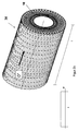
- FIG. 2a After applying a certain layer thickness, which depends on the fiber composite component geometry and other requirements, one or more windings with impregnated fiber strands, so-called Rovings 15 (monofilaments) or a band of multiple parallel laid rovings, is applied to a sufficient compaction of the fiber composite component.
- Rovings 15 are preferably wound at an angle of ⁇ 45 ° (to stabilize the ply structure) and 90 ° (for densification) in a second fiber material ply.
- a reversal of the feed direction is possible only on the front sides without complex tools. This proportion of the occupancy results in a homogeneous occupancy in the longitudinal and circumferential direction (see FIGS.
- reinforcing ribbons 22 are in the direction of the desired load distribution and preferably consist of fibers in the tape longitudinal direction.
- FIG. 3 on the right is the area for later concentrated force application, for example by gluing, bolting etc. (concentrated in the circumferential direction), while in FIG. 3 left is the later connection or clamping area (distributed force introduction in the circumferential direction).
- FIG. 3 bottom thickness is also shown d, that is, all applied fiber layers, depending on the length 1 of the fiber composite component 14 shown.
- additional local reinforcing bands or reinforcements are present.
- the former coil body 10 is removed, resulting in the finished fiber composite component.
- FIG. 4 shows a finished wound fiber composite component 14 according to the present invention, which is designed as a "double component", therefore length 21, and is divided by later mechanical separation in the middle region into two individual components.
- two fiber composite components are produced simultaneously by first making a molded wound body 10 of increased length or two opposing cores twisted against each other according to the fiber composite component requirement as a "double component” which is then split in the middle. This has the advantage that less material waste is obtained, since otherwise must be wound with supernatant.
- FIG. 5 shows a fiber composite component according to a particular embodiment of the invention, more particularly a rotor blade connection 16 for a rotor blade for a wind turbine with further rotor blade components 18 and 20.
- the fiber composite component 14 can also not be produced rotationally symmetrically using a method according to a particular embodiment of the present invention.
- FIGS. 1 and 2 shown steps not sequentially, but in whole or in part simultaneously (for example, by two independently controlled feed slide) are performed.
- a defined wall thickness profile can be generated from the flange (rotor blade connection) in the direction of the rotor blade.
Landscapes
- Engineering & Computer Science (AREA)
- Mechanical Engineering (AREA)
- Chemical & Material Sciences (AREA)
- Composite Materials (AREA)
- Textile Engineering (AREA)
- Sustainable Development (AREA)
- Sustainable Energy (AREA)
- Combustion & Propulsion (AREA)
- General Engineering & Computer Science (AREA)
- Life Sciences & Earth Sciences (AREA)
- Moulding By Coating Moulds (AREA)
- Wind Motors (AREA)
- Reinforced Plastic Materials (AREA)
- Laminated Bodies (AREA)
Abstract
Description
- Die vorliegende Erfindung betrifft ein Faserverbundbauteil aus gewickeltem kunstharzgetränktem Fasermaterial und ein Verfahren zur Herstellung desselben.
- Der vorliegenden Erfindung liegt die Aufgabe zugrunde, ein zumindest im wesentlichen gewickeltes Faserverbundbauteil mit einer in Umfangs- und Längsrichtung desselben angepassten Steifigkeits- und Materialverteilung bereitzustellen.
- Erfindungsgemäß wird diese Aufgabe gelöst durch ein Faserverbundbauteil aus gewickeltem kunstharzgetränktem Fasermaterial, wobei das Fasermaterial in mindestens zwei übereinander liegenden Fasermateriallagen angeordnet ist und in der nachfolgend ersten genannten Fasermateriallage das Fasermaterial ein Fasergelege, ein Fasergewebe oder eine Fasermatte ist und so gewickelt ist, dass deren Lagendicke in Umfangsrichtung des Faserverbundbauteils zumindest nahezu konstant ist und in Längsrichtung des Faserverbundbauteils variiert, und in der darauf aufliegenden oder darunter liegenden, nachfolgend zweiten genannten Fasermateriallage das Fasermaterial ein Roving ist und so gewickelt ist, dass deren Lagendicke in Umfangs- und Längsrichtung des Faserverbundbauteils zumindest nahezu konstant ist. Selbstverständlich müssen die beiden Fasermateriallagen nicht die untersten beiden Lagen sein. Bedarfsweise kann darunter nämlich noch eine weitere Lage vorgesehen sein.
- Des weiteren wird diese Aufgabe gelöst durch ein Verfahren zur Herstellung eines Faserverbundbauteils aus gewickeltem kunstharzgetränktem Fasermaterial, insbesondere nach einem der vorangehenden Ansprüche, umfassend die Schritte: Wickeln eines Fasermaterials, das ein Fasergelege, ein Fasergewebe oder eine Fasermatte ist, in einer ersten Fasermateriallage auf einen Formwickelkörper derart, dass die Lagendicke der ersten Fasermateriallage in Umfangsrichtung des Faserverbundbauteils zumindest nahezu konstant ist und in Längsrichtung des Faserverbundbauteils variiert, und Wickeln eines Fasermaterials, das ein Roving ist, in einer zweiten Fasermateriallage auf die erste Fasermateriallage derart, dass die Lagendicke der zweiten Fasermateriallage in Umfangs- und Längsrichtung des Faserverbundbauteils zumindest nahezu konstant ist, oder umgekehrtes Anordnen der ersten und zweiten Fasermateriallagen.
- Bei dem Faserverbundbauteil ist das Fasermaterial der ersten Fasermateriallage günstigerweise unter einem Winkel im Bereich von 0° bis ca. 10° zur Längsrichtung des Faserverbundbauteils orientiert. Diese Lage wird mit geringer Steigung, vorzugsweise überlappend, gewickelt.
- Alternativ oder zusätzlich kann das Fasermaterial der zweiten Fasermateriallage unter einem Winkel von ca. ±45° oder ca. ±90° zur Längsrichtung des Faserverbundbauteils kreuzförmig gewickelt sein. Es handelt sich dabei um bevorzugte Werte für den Winkel. Grundsätzlich kann der Winkel einen beliebigen Wert annehmen.
- Gemäß einer besonderen Ausführungsform der Erfindung liegt eine dritte Fasermateriallage auf der ersten oder zweiten Fasermateriallage auf, in der Fasermaterial analog zu demjenigen der ersten Fasermateriallage beschaffen und gewickelt ist. Analog soll dabei nicht unbedingt bedeuten, dass das Fasermaterial der dritten Fasermateriallage identisch beschaffen und gewickelt ist.
- Vorteilhafterweise ist auf der ersten, zweiten oder dritten Fasermateriallage in mindestens einem Bereich eine lokale Verstärkung zur Lastverteilung aufgebracht.
- Insbesondere kann dabei vorgesehen sein, dass die Verstärkung ein Verstärkungsband ist, das vorzugsweise aus Fasern in seiner Längsrichtung besteht.
- Gemäß einer weiteren besonderen Ausführungsform der Erfindung liegt mindestens eine weitere Fasermateriallage auf der ersten, zweiten oder dritten Fasermateriallage mit darauf aufgebrachter mindestens einer lokaler Verstärkung auf, in der das Fasermaterial analog zu demjenigen der zweiten Fasermateriallage beschaffen und gewickelt ist. Hier soll ebenfalls analog nicht unbedingt bedeuten, dass das Fasermaterial der weiteren Fasermateriallage bzw. die Fasermaterialien der weiteren Fasermateriallagen identisch beschaffen und gewickelt ist.
- Insbesondere kann vorgesehen sein, dass das Faserverbundbauteil ein Blattanschluss für ein Rotorblatt einer Windenergieanlage ist.
- Bei dem erfindungsgemäßen Verfahren wird das Fasermaterial der ersten Fasermateriallage vorzugsweise unter einem Winkel im Bereich von 0° bis ca. 10° zur Längsrichtung des Faserverbundbauteils, vorzugsweise überlappend, gewickelt.
- Alternativ oder zusätzlich kann vorgesehen sein, dass das Fasermaterial der zweiten Fasermateriallage unter einem Winkel von ca. ±45° oder ca. ±90° zur Längsrichtung des Faserverbundbauteils kreuzförmig gewickelt wird. Es handelt sich dabei um bevorzugte Werte für den Winkel. Grundsätzlich kann der Winkel einen beliebigen Wert annehmen.
- Gemäß einer besonderen Ausführungsform der Erfindung umfasst das Verfahren ferner: Wickeln eines Fasermaterials, das ein Fasergelege, ein Fasergewebe oder eine Fasermatte ist, in einer dritten Fasermateriallage auf die erste oder zweite Fasermateriallage derart, dass die Lagendicke der dritten Fasermateriallage in Umfangsrichtung des Faserverbundbauteils zumindest nahezu konstant ist und in Längsrichtung des Faserverbundbauteils variiert.
- Vorteilhafterweise wird auf der ersten oder zweiten Fasermateriallage in mindestens einem Bereich eine lokale Verstärkung zur Lastverteilung aufgebracht wird, wobei die Verstärkung vorzugsweise ein Verstärkungsband ist, das vorzugsweise aus Fasern in seiner Längsrichtung besteht.
- Wiederum vorteilhafterweise wird auf der dritten Fasermateriallage in mindestens einem Bereich eine lokale Verstärkung zur Lastverteilung aufgebracht, wobei die Verstärkung vorzugsweise ein Verstärkungsband ist, das vorzugsweise aus Fasern in seiner Längsrichtung besteht.
- Eine weitere besondere Ausführungsform der Erfindung des Verfahrens umfasst ferner: Wickeln mindestens einer weiteren Fasermateriallage auf die erste oder zweite Fasermateriallage mit darauf aufgebrachter mindestens einer lokaler Verstärkung, wobei das Fasermaterial ein Roving ist und derart gewickelt wird, dass die Lagendicke der Fasermateriallage in Umfangs- und Längsrichtung des Faserverbundbauteils zumindest nahezu konstant ist.
- Wiederum eine weitere besondere Ausführungsform des Verfahrens umfasst ferner: Wickeln mindestens einer weiteren Fasermateriallage auf die dritte Fasermateriallage mit darauf auf gebrachter mindestens einer lokaler Verstärkung, wobei das Fasermaterial ein Roving ist und derart gewickelt wird, dass die Lagendicke der Fasermateriallage in Umfangs- und Längsrichtung des Faserverbundbauteils zumindest nahezu konstant ist.
- Schließlich ist das Faserverbundbauteil vorzugsweise ein Blattanschluss für ein Rotorblatt einer Windenergieanlage.
- Der Erfindung liegt die überraschende Erkenntnis zugrunde, dass durch ein spezielles Wickelverfahren die Fertigung eines Faserverbundbauteils mit einer in Umfangs- und Längsrichtung des Faserverbundbauteils angepassten Steifigkeits- und Materialverteilung möglich ist. Insbesondere lässt sich damit ein Faserverbundbauteil im Wickelverfahren herstellen, das auf einer Seite einen vorzugsweise rotationssymmetrischen Verbindungsbereich (Lager oder Flansch, bei dem die Lasteinleitung über den Umfang verteilt ist), wobei der Verbindungsbereich durch nachträgliches Bearbeiten, wie zum Beispiel Bohren etc., erstellt bzw. fertiggestellt werden kann, und auf der anderen Seite einen Bereich mit konzentrierten Krafteinleitungsbereichen aufweist, die nicht gleichförmig über den Umfang verteilt sind, und über lokale Verbindungselemente, wie zum Beispiel Schrauben, Bolzen etc., oder Überklebungen in Bereichen, die in erster Näherung parallel zur Bauteilachse sind, verlaufen. Mit anderen Worten kann ein Übergang von besagtem Verbindungsbereich zu besagtem Bereich mit konzentrierten Krafeinleitungsbereichen hergestellt werden. Der Bereich mit konzentrierten Krafteinleitungsbereichen kann rotationssymmetrisch oder an die Erfordernisse eines sich daran anschließenden Bauteils ausgeführt werden, zum Beispiel elliptisch oder angenähert an eine Profilform oder Teile desselben.
- Weitere Merkmale und Vorteile der Erfindung ergeben sich aus den beigefügten Ansprüchen und der nachfolgenden Beschreibung, in der Ausführungsbeispiele anhand der schematischen Zeichnungen im einzelnen erläutert sind, wobei
- Figuren 1 bis 3
- Phasen eines Verfahrens gemäß einer besonderen Ausfiihrungsform der vorliegenden Erfindung zeigen;
- Figur 4
- eine perspektivische Ansicht eines Faserverbundbauteils gemäß einer besonderen Ausführungsform der Erfindung zeigt;
- Figur 5
- eine perspektivische Ansicht eines Faserverbundbauteils gemäß einer weiteren besonderen Ausfiihrungsform der Erfindung in Verbindung mit Rotorblattkomponenten einer Windenergieanlage zeigt; und
- Figur 6
- eine perspektivische Ansicht eines Faserverbundbauteils gemäß einer weiteren besonderen Ausführungsform der vorliegenden Erfindung zeigt.
-
Figur 1 zeigt das Bewickeln eines Formwickelkörpers bzw. Formkerns 10 mit einem Fasermaterial, hier einem harzgetränkten Faserband 12. Derartige Faserbänder können als Fasergelege mit nahezu beliebiger Faserorientierung hergestellt werden. Im vorliegenden Fall besteht das Faserband aus einem Anteil Fasern in Bandlängsrichtung und einem weiteren Anteil nahezu quer zur Faserbandrichtung. Es sind zwei oder mehr Richtungen vorzugsweise symmetrisch zur Querrichtung des Faserbandes möglich. Der Faseranteil je Richtung orientiert sich an den Steifigkeits- und Festigkeitsanforderungen an das Faserverbundbauteil 14. Das Faserband 12 wird mit geringer Steigung, das heißt unter einem Winkel im Bereich von 0° bis 10° zur durch einen Pfeil gekennzeichneten Längsrichtung des Faserverbundbauteils auf den Formwickelkörper 10 gewickelt, wobei sich die Faserbänder überlappen. Die Kraftübertragung von einem Faserband 12 zum anderen erfolgt interlaminar über den Harz-FaserVerbund. - Durch betragsmäßiges Ändern und Richtungswechsel an Umkehrpunkten des Vorschubs beim Aufwickeln des Faserbandes 12 auf den Formwickelkörper 10 können nahezu beliebige stetige Bandstärkenverteilungen erzeugt werden. Der Formwickelkörper 10 wird also in Umfangsrichtung jeweils nahezu gleiche Belegung aufweisen, kann aber in Längsrichtung angepasst werden. Mit anderen Worten resultiert eine erste Fasermateriallage, deren Lagendicke in Umfangsrichtung des Faserverbundbauteils 14 zumindest nahezu konstant ist und in Längsrichtung des Faserverbundbauteils 14 variiert.
- Während des vorangehend beschriebenen Wickelns können Faserbänder mit unterschiedlichen Orientierungen eingesetzt werden. Zudem ist in
Figur 1 die Dicke d des Faserverbundbauteils über der Länge 1 desselben mit beispielhafter Darstellung von Umkehrpunkten gezeigt. - Wie
Figur 2a gezeigt ist, wird/werden nach Aufbringen einer gewissen Lagendicke, die von der Faserverbundbauteilgeometrie und anderen Anforderungen abhängt, eine oder mehrere Wicklungen mit getränkten Fasersträngen, sogenannten Rovings 15 (Einzelfäden) oder einem Band aus mehreren parallel verlegten Rovings, aufgebracht, um eine ausreichende Verdichtung des Faserverbundbauteils zu erhalten. Diese Rovings 15 werden vorzugsweise in einem Winkel von ±45° (zur Stabilisierung des Lagenaufbaus) und 90° (zur Verdichtung) in einer zweiten Fasermateriallage gewickelt. Bei Wickelwinkeln bis ca. 60° ist eine Umkehr der Vorschubrichtung nur über die Stirnseiten ohne aufwendige Hilfsmittel möglich. Dieser Anteil der Belegung ergibt eine in Längs- und Umfangsrichtung homogene Belegung (sieheFiguren 2a und2b ). Mit anderen Worten resultiert eine in Umfangs- und Längsrichtung des Faserverbundbauteils zumindest nahezu konstante Lagendicke der zweiten Fasermateriallage (siehe auch die Darstellung der Dicke d der zweiten Fasermateriallage über die Länge 1 des Faserverbundmaterials). - Danach kann nach Bedarf entweder mindestens eine weitere Fasermateriallage, wie in
Figur 1 gezeigt, aufgebracht werden (nicht gezeigt) oder können gezielt in bestimmten Bereichen Verstärkungsbänder 22 zur Lastverteilung aufgebracht werden (sieheFigur 3 ). Diese Verstärkungsbänder 22 liegen in Richtung der gewünschten Lastverteilung und bestehen vorzugsweise aus Fasern in Bandlängsrichtung. InFigur 3 rechts befindet sich der Bereich für spätere konzentrierte Krafteinleitung, zum Beispiel durch Klebung, Verbolzung etc. (konzentriert in Umfangsrichtung), während inFigur 3 links sich der spätere Verbindungs- bzw. Einspannbereich (verteilte Krafteinleitung in Umfangsrichtung) befindet. InFigur 3 ist unten links zudem die genannte Dicke d, das heißt aller aufgebrachten Fasermateriallagen, in Abhängigkeit von der Länge 1 des Faserverbundbauteils 14 gezeigt. In Längs- und Querrichtung sind zusätzliche lokale Verstärkungsbänder bzw. Verstärkungen vorhanden. - Nach Aufbringen der Verstärkungsbänder kann es sinnvoll sein, eine oder mehrere Fasermateriallage(n), wie in
Figuren 2a und2b gezeigt, zur Verdichtung aufzubringen (nicht gezeigt). - Anschließend kann/können je nach gewünschtem Lagenaufbau die in den
Figuren 1 bis 3 gezeigten Verfahrensschritte ein- oder mehrfach, ganz oder teilweise wiederholt werden. - Am Ende wird der Formwickelkörper 10 entfernt, so dass das fertige Faserverbundbauteil resultiert.
-
Figur 4 zeigt ein fertig gewickeltes Faserverbundbauteil 14 gemäß der vorliegenden Erfindung, das als "Doppelbauteil", daher Länge 21, ausgeführt ist und durch späteres mechanisches Trennen im mittleren Bereich in zwei Einzelbauteile aufgeteilt wird. Mit anderen Worten werden zwei Faserverbundbauteile gleichzeitig hergestellt, indem ein Formwickelkörper 10 mit vergrößerter Länge oder zwei gegeneinander gesetzte und entsprechend der Faserverbundbauteilanforderung gegeneinander verdrehte Kerne zunächst als ein "Doppelbauteil" hergestellt werden, die danach in der Mitte geteilt werden. Dies weist den Vorteil auf, dass weniger Materialverschnitt anfällt, da andernfalls mit Überstand gewickelt werden muss. -
Figur 5 zeigt ein Faserverbundbauteil gemäß einer besonderen Ausführungsform der Erfindung, genauer gesagt einen Rotorblattanschluss 16 für ein Rotorblatt für eine Windenergieanlage mit weiteren Rotorblattkomponenten 18 und 20. - Schließlich ergibt sich aus
Figur 6 , dass das Faserverbundbauteil 14 gemäß einer besonderen Ausführungsform der vorliegenden Erfindung mit einem Verfahren gemäß einer besonderen Ausfiihrungsform der vorliegenden Erfindung auch nicht rotationssymmetrisch gefertigt werden kann. - Gemäß einer weiteren besonderen Ausführungsform der Erfindung kann vorgesehen sein, dass die in den
Figuren 1 und2 gezeigten Schritte nicht nacheinander, sondern ganz oder teilweise gleichzeitig (zum Beispiel durch zwei unabhängig gesteuerte Vorschubschlitten) durchgeführt werden. - Wie die obigen Ausführungen gezeigt haben, lässt sich zumindest gemäß besonderen Ausführungsformen des erfindungsgemäßen Verfahrens ein definierter Wandstärkenverlauf vom Flansch (Rotorblattanschluss) in Richtung Rotorblatt erzeugen.
- Die in der vorstehenden Beschreibung, in den Zeichnungen sowie in den Ansprüchen offenbarten Merkmale der Erfindung können sowohl einzeln als auch in beliebigen Kombinationen für die Verwirklichung der Erfindung in ihren verschiedenen Ausführungsformen wesentlich sein.
-
- 10
- Formwickelkörper bzw. Formkern
- 12
- Faserband
- 14
- Faserverbundbauteil
- 15
- Roving
- 16
- Rotorblattanschluss
- 18, 20
- Rotorblattkomponenten
- 22
- Verstärkungsbänder
- d
- Dicke des Faserverbundbauteils oder der Fasermateriallage (Faserverbundlage)
- 1
- Länge des Faserverbundbauteils
Claims (17)
- Faserverbundbauteil (14) aus gewickeltem kunstharzgetränktem Fasermaterial, wobei das Fasermaterial in mindestens zwei übereinander liegenden Fasermateriallagen angeordnet ist und in der nachfolgend ersten genannten Fasermateriallage das Fasermaterial ein Fasergelege, ein Fasergewebe oder eine Fasermatte ist und so gewickelt ist, dass deren Lagendicke in Umfangsrichtung des Faserverbundbauteils (14) zumindest nahezu konstant ist und in Längsrichtung des Faserverbundbauteils (14) variiert, und in der darauf aufliegenden oder darunter liegenden, nachfolgend zweiten genannten Fasermateriallage das Fasermaterial ein Roving (15) ist und so gewickelt ist, dass deren Lagendicke in Umfangs- und Längsrichtung des Faserverbundbauteils (14) zumindest nahezu konstant ist.
- Faserverbundbauteil (14) nach Anspruch 1, dadurch gekennzeichnet, dass das Fasermaterial der ersten Fasermateriallage unter einem Winkel im Bereich von 0° bis ca. 10° zur Längsrichtung des Faserverbundbauteils (14) orientiert ist.
- Faserverbundbauteil (14) nach Anspruch 1 oder 2, dadurch gekennzeichnet, dass das Fasermaterial der zweiten Fasermateriallage unter einem Winkel von ca. ± 45 ° oder ca. ± 90 ° zur Längsrichtung des Faserverbundbauteils (14) kreuzförmig gewickelt ist.
- Faserverbundbauteil (14) nach einem der Ansprüche 1 bis 3, dadurch gekennzeichnet, dass eine dritte Fasermateriallage auf der ersten oder zweiten Fasermateriallage aufliegt, in der Fasermaterial analog zu demjenigen der ersten Fasermateriallage beschaffen und gewickelt ist.
- Faserverbundbauteil (14) nach einem der vorangehenden Ansprüche, dadurch gekennzeichnet, dass auf der ersten, zweiten oder dritten Fasermateriallage in mindestens einem Bereich eine lokale Verstärkung zur Lastverteilung aufgebracht ist.
- Faserverbundbauteil (14) nach Anspruch 5, dadurch gekennzeichnet, dass die Verstärkung ein Verstärkungsband (22) ist, das vorzugsweise aus Fasern in seiner Längsrichtung besteht.
- Faserverbundbauteil (14) nach einem der Ansprüche 5 oder 6, dadurch gekennzeichnet, dass mindestens eine weitere Fasermateriallage auf der ersten, zweiten oder dritten Fasermateriallage mit darauf aufgebrachter mindestens einer lokaler Verstärkung aufliegt, in der das Fasermaterial analog zu demjenigen der zweiten Fasermateriallage beschaffen und gewickelt ist.
- Faserverbundbauteil (14) nach einem der vorangehenden Ansprüche, dadurch gekennzeichnet, dass es ein Blattanschluss für ein Rotorblatt einer Windenergieanlage ist.
- Verfahren zur Herstellung eines Faserverbundbauteils (14) aus gewickeltem kunstharzgetränktem Fasermaterial, insbesondere nach einem der vorangehenden Ansprüche, umfassend die Schritte:- Wickeln eines Fasermaterials, das ein Fasergelege, ein Fasergewebe oder eine Fasermatte ist, in einer ersten Fasermateriallage auf einen Formwickelkörper (10) derart, dass die Lagendicke der ersten Fasermateriallage in Umfangsrichtung des Faserverbundbauteils (14) zumindest nahezu konstant ist und in Längsrichtung des Faserverbundbauteils (14) variiert, und- Wickeln eines Fasermaterials, das ein Roving (15) ist, in einer zweiten Fasermateriallage auf die erste Fasermateriallage derart, dass die Lagendicke der zweiten Fasermateriallage in Umfangs- und Längsrichtung des Faserverbundbauteils (14) zumindest nahezu konstant ist,- oder umgekehrtes Anordnen der ersten und zweiten Fasermateriallagen.
- Verfahren nach Anspruch 9, dadurch gekennzeichnet, dass das Fasermaterial der ersten Fasermateriallage unter einem Winkel im Bereich von 0 ° bis ca. 10 ° zur Längsrichtung des Faserverbundbauteils (14), vorzugsweise überlappend, gewickelt wird.
- Verfahren nach Anspruch 9 oder 10, dadurch gekennzeichnet, dass das Fasermaterial der zweiten Fasermateriallage unter einem Winkel von ca. ± 45 ° oder ca. ± 90 ° zur Längsrichtung des Faserverbundbauteils (14) kreuzförmig gewickelt wird.
- Verfahren nach einem der Ansprüche 9 bis 11, dadurch gekennzeichnet, dass es ferner umfasst:- Wickeln eines Fasermaterials, das ein Fasergelege, ein Fasergewebe oder eine Fasermatte ist, in einer dritten Fasermateriallage auf die erste oder zweite Fasermateriallage derart, dass die Lagendicke der dritten Fasermateriallage in Umfangsrichtung des Faserverbundbauteils (14) zumindest nahezu konstant ist und in Längsrichtung des Faserverbundbauteils (14) variiert.
- Verfahren nach einem der Ansprüche 9 bis 11, dadurch gekennzeichnet, dass auf der ersten oder zweiten Fasermateriallage in mindestens einem Bereich eine lokale Verstärkung zur Lastverteilung aufgebracht wird, wobei die Verstärkung vorzugsweise ein Verstärkungsband (22) ist, das vorzugsweise aus Fasern in seiner Längsrichtung besteht.
- Verfahren nach Anspruch 12, dadurch gekennzeichnet, dass auf der dritten Fasermateriallage in mindestens einem Bereich eine lokale Verstärkung zur Lastverteilung aufgebracht wird, wobei die Verstärkung vorzugsweise ein Verstärkungsband (22) ist, das vorzugsweise aus Fasern in seiner Längsrichtung besteht.
- Verfahren nach Anspruch 13, dadurch gekennzeichnet, dass es ferner umfasst:- Wickeln mindestens einer weiteren Fasermateriallage auf die erste oder zweite Fasermateriallage mit darauf aufgebrachter mindestens einer lokaler Verstärkung, wobei das Fasermaterial ein Roving ist und derart gewickelt wird, dass die Lagendicke der Fasermateriallage in Umfangs- und Längsrichtung des Faserverbundbauteils (14) zumindest nahezu konstant ist.
- Verfahren nach Anspruch 14, dadurch gekennzeichnet, dass es ferner umfasst:- Wickeln mindestens einer weiteren Fasermateriallage auf die dritte Fasermateriallage mit darauf aufgebrachter mindestens einer lokaler Verstärkung, wobei das Fasermaterial ein Roving ist und derart gewickelt wird, dass die Lagendicke der Fasermateriallage in Umfangs- und Längsrichtung des Faserverbundbauteils (14) zumindest nahezu konstant ist.
- Verfahren nach einem der Ansprüche 9 bis 16, dadurch gekennzeichnet, dass das Faserverbundbauteil (14) ein Blattanschluss für ein Rotorblatt einer Windenergieanlage ist.
Priority Applications (5)
| Application Number | Priority Date | Filing Date | Title |
|---|---|---|---|
| EP10001871.2A EP2361752B1 (de) | 2010-02-24 | 2010-02-24 | Faserverbundbauteil und Verfahren zur Herstellung desselben |
| PL10001871T PL2361752T3 (pl) | 2010-02-24 | 2010-02-24 | Włóknisty komponent kompozytowy i sposób jego wytwarzania |
| PT100018712T PT2361752E (pt) | 2010-02-24 | 2010-02-24 | Componente de compósito fibroso e respectivo processo de fabricação |
| ES10001871.2T ES2541204T3 (es) | 2010-02-24 | 2010-02-24 | Componente de material compuesto de fibras y procedimiento para la producción del mismo |
| DK10001871.2T DK2361752T3 (en) | 2010-02-24 | 2010-02-24 | Component-component fiber and process for producing same |
Applications Claiming Priority (1)
| Application Number | Priority Date | Filing Date | Title |
|---|---|---|---|
| EP10001871.2A EP2361752B1 (de) | 2010-02-24 | 2010-02-24 | Faserverbundbauteil und Verfahren zur Herstellung desselben |
Publications (2)
| Publication Number | Publication Date |
|---|---|
| EP2361752A1 true EP2361752A1 (de) | 2011-08-31 |
| EP2361752B1 EP2361752B1 (de) | 2015-04-08 |
Family
ID=42651219
Family Applications (1)
| Application Number | Title | Priority Date | Filing Date |
|---|---|---|---|
| EP10001871.2A Active EP2361752B1 (de) | 2010-02-24 | 2010-02-24 | Faserverbundbauteil und Verfahren zur Herstellung desselben |
Country Status (5)
| Country | Link |
|---|---|
| EP (1) | EP2361752B1 (de) |
| DK (1) | DK2361752T3 (de) |
| ES (1) | ES2541204T3 (de) |
| PL (1) | PL2361752T3 (de) |
| PT (1) | PT2361752E (de) |
Cited By (10)
| Publication number | Priority date | Publication date | Assignee | Title |
|---|---|---|---|---|
| DE102014214405A1 (de) | 2013-07-24 | 2015-01-29 | Voith Patent Gmbh | Energieverzehrvorrichtung |
| CN108349173A (zh) * | 2015-09-23 | 2018-07-31 | 白昼国际有限公司 | 切割垫及其制造方法 |
| DE102018100941A1 (de) * | 2018-01-17 | 2019-07-18 | Wobben Properties Gmbh | Verfahren zum Herstellen von Komponenten einer Windenergieanlage, insbesondere eines Windenergieanlagen-Rotorblattes |
| EP2739452B1 (de) * | 2011-08-05 | 2019-10-16 | SGL Carbon SE | Verfahren zum herstellen eines bauteils aus einem faserverbundwerkstoff umfassend wickellagen |
| US11404854B2 (en) | 2017-06-21 | 2022-08-02 | C-Ling Limited | Pull-in head assembly |
| EP3468781B1 (de) | 2016-06-14 | 2022-08-03 | Nordex Blade Technology Centre APS | Verbindungsstruktur einer windturbinenschaufel und verfahren zu deren herstellung |
| US11411376B2 (en) | 2017-06-21 | 2022-08-09 | C-Ling Limited | Pull-in head assembly |
| US11418016B2 (en) | 2017-06-21 | 2022-08-16 | C-Ling Limited | Pull-in head assembly |
| US11473563B2 (en) | 2016-09-28 | 2022-10-18 | C-Ling Limited | Annular seal member locatable against a wall element of an offshore structure |
| DE102021118608A1 (de) | 2021-07-19 | 2023-01-19 | Hawart Sondermaschinenbau Gmbh | Rotorblatt für eine Windkraftanlage sowie Verfahren und Vorrichtung zum Herstellen eines Flanscheinlegers für das Rotorblatt |
Citations (4)
| Publication number | Priority date | Publication date | Assignee | Title |
|---|---|---|---|---|
| US4247258A (en) * | 1978-11-13 | 1981-01-27 | United Technologies Corporation | Composite wind turbine blade |
| US4273601A (en) * | 1977-10-31 | 1981-06-16 | Structural Composites Industries, Inc. | Method for the production of elongated resin impregnated filament composite structures |
| US4381960A (en) * | 1981-12-28 | 1983-05-03 | United Technologies Corporation | Method of manufacturing a filament wound article |
| DE102008045601A1 (de) * | 2008-06-27 | 2009-12-31 | Repower Systems Ag | Rotorblatt für eine Windenergieanlage und Verfahren und Fertigungform zu seiner Fertigung |
-
2010
- 2010-02-24 EP EP10001871.2A patent/EP2361752B1/de active Active
- 2010-02-24 ES ES10001871.2T patent/ES2541204T3/es active Active
- 2010-02-24 DK DK10001871.2T patent/DK2361752T3/en active
- 2010-02-24 PT PT100018712T patent/PT2361752E/pt unknown
- 2010-02-24 PL PL10001871T patent/PL2361752T3/pl unknown
Patent Citations (4)
| Publication number | Priority date | Publication date | Assignee | Title |
|---|---|---|---|---|
| US4273601A (en) * | 1977-10-31 | 1981-06-16 | Structural Composites Industries, Inc. | Method for the production of elongated resin impregnated filament composite structures |
| US4247258A (en) * | 1978-11-13 | 1981-01-27 | United Technologies Corporation | Composite wind turbine blade |
| US4381960A (en) * | 1981-12-28 | 1983-05-03 | United Technologies Corporation | Method of manufacturing a filament wound article |
| DE102008045601A1 (de) * | 2008-06-27 | 2009-12-31 | Repower Systems Ag | Rotorblatt für eine Windenergieanlage und Verfahren und Fertigungform zu seiner Fertigung |
Cited By (13)
| Publication number | Priority date | Publication date | Assignee | Title |
|---|---|---|---|---|
| EP2739452B1 (de) * | 2011-08-05 | 2019-10-16 | SGL Carbon SE | Verfahren zum herstellen eines bauteils aus einem faserverbundwerkstoff umfassend wickellagen |
| DE102014214405A1 (de) | 2013-07-24 | 2015-01-29 | Voith Patent Gmbh | Energieverzehrvorrichtung |
| CN108349173A (zh) * | 2015-09-23 | 2018-07-31 | 白昼国际有限公司 | 切割垫及其制造方法 |
| CN108349173B (zh) * | 2015-09-23 | 2020-05-08 | 青岛博发科技有限公司 | 制造切割垫背衬的方法和切割垫 |
| EP3468781B1 (de) | 2016-06-14 | 2022-08-03 | Nordex Blade Technology Centre APS | Verbindungsstruktur einer windturbinenschaufel und verfahren zu deren herstellung |
| US12071926B2 (en) | 2016-09-28 | 2024-08-27 | C-Ling Limited | Apparatus |
| US11473563B2 (en) | 2016-09-28 | 2022-10-18 | C-Ling Limited | Annular seal member locatable against a wall element of an offshore structure |
| US11418016B2 (en) | 2017-06-21 | 2022-08-16 | C-Ling Limited | Pull-in head assembly |
| US11411376B2 (en) | 2017-06-21 | 2022-08-09 | C-Ling Limited | Pull-in head assembly |
| US11404854B2 (en) | 2017-06-21 | 2022-08-02 | C-Ling Limited | Pull-in head assembly |
| WO2019141758A1 (de) | 2018-01-17 | 2019-07-25 | Wobben Properties Gmbh | Verfahren zum herstellen von komponenten einer windenergieanlage, insbesondere eines windenergieanlagen-rotorblattes |
| DE102018100941A1 (de) * | 2018-01-17 | 2019-07-18 | Wobben Properties Gmbh | Verfahren zum Herstellen von Komponenten einer Windenergieanlage, insbesondere eines Windenergieanlagen-Rotorblattes |
| DE102021118608A1 (de) | 2021-07-19 | 2023-01-19 | Hawart Sondermaschinenbau Gmbh | Rotorblatt für eine Windkraftanlage sowie Verfahren und Vorrichtung zum Herstellen eines Flanscheinlegers für das Rotorblatt |
Also Published As
| Publication number | Publication date |
|---|---|
| PT2361752E (pt) | 2015-08-26 |
| PL2361752T3 (pl) | 2015-12-31 |
| ES2541204T3 (es) | 2015-07-16 |
| EP2361752B1 (de) | 2015-04-08 |
| DK2361752T3 (en) | 2015-07-13 |
Similar Documents
| Publication | Publication Date | Title |
|---|---|---|
| EP2361752B1 (de) | Faserverbundbauteil und Verfahren zur Herstellung desselben | |
| DE3851023T2 (de) | Kohlenstoffaserverstärkte Harz-Pultrusionsgegenstände und Verfahren zu ihrer Herstellung. | |
| EP0113841B1 (de) | Verfahren zur Herstellung eines Formkörpers aus Verbundmaterial und nach diesem Verfahren hergestellter Formkörper | |
| EP3496936B1 (de) | Gurt aus vorgefertigten elementen mit gelege und ein verfahren zu seiner fertigung | |
| EP2046564B1 (de) | Verfahren zur Herstellung von mehreren Faserverbundbauteilen | |
| EP2082903A2 (de) | Fahrzeugfeder aus Faserverbundwerkstoff | |
| DE2942913A1 (de) | Rohrteil mit flansch | |
| DE102011002840A1 (de) | Faserverstärktes Verbundbauteil und Verfahren zum Herstellen eines faserverstärkten Verbundbauteils | |
| DE102007049347B4 (de) | Verfahren zur Herstellung eines Vorformlings aus Halbzeug, zur Herstellung eines ringförmigen Rahmenprofils, Verwendung des Vefahrens, sowie Rahmenprofil | |
| DE2757965A1 (de) | Schubuebertragungselement und verfahren zu dessen herstellung | |
| DE102010005987B4 (de) | Verfahren zur Herstellung von Hohlkörpern mit bundförmigen Verstärkungen | |
| DE102010050065B4 (de) | Blattfeder aus einem Faserverbundwerkstoff mit unterschiedlich langen Faserlagen sowie Verfahren zu deren Herstellung | |
| EP2670581B1 (de) | Verfahren, halbzeug für die herstellung eines faserverstärkten bauteils einer windenergieanlage und verwendung des halbzeuges | |
| DE102008057463B4 (de) | Feder aus einem Faserverbundwerkstoff sowie Verfahren und Vorrichtung zur Herstellung derselben | |
| EP3127686A2 (de) | Verfahren zur herstellung eines bauteils eines rotorblattes einer windenergieanlage | |
| EP3490782B1 (de) | Verfahren zum herstellen eines dreidimensionalen, vielschichtigen faserverbundteils | |
| DE102008057462B4 (de) | Feder aus einem Faserverbundwerkstoff sowie Verfahren und Vorrichtung zur Herstellung derselben | |
| DE69314905T2 (de) | Verfahren zum Herstellen von rohrförmigen Elementen aus kunstharzgebundenen Fasern, die ineinanderschiebbar sind, um eine Angelrute mit kontrollierter Bewegung zu bilden, und mit diesem Verfahren hergestellte Elemente | |
| DE102007015516B4 (de) | Kunststoff-Faser-Verbundbauteil in Form eines Profils mit über die Länge variierendem Profilquerschnitt | |
| EP4003712B1 (de) | Verfahren zum herstellen eines rohrteils mit einem innengewinde und rohrteil mit einem innengewinde | |
| EP0261375B1 (de) | Verfahren zum Herstellen eines Faserverbund-Hohlträgers | |
| DE102014105795B4 (de) | Textilbetonteil und Verfahren zu dessen Herstellung | |
| DE102016007464A1 (de) | Verstärkungsstreifen für ein rohrförmiges bauteil aus verbundmaterial | |
| DE102018125863A1 (de) | Verfahren zur Herstellung eines Faserverbund-Gelenkwellenrohres und Faserverbund-Gelenkwellenrohr | |
| DE2543579A1 (de) | Walzenbezug sowie verfahren zu seiner herstellung |
Legal Events
| Date | Code | Title | Description |
|---|---|---|---|
| PUAI | Public reference made under article 153(3) epc to a published international application that has entered the european phase |
Free format text: ORIGINAL CODE: 0009012 |
|
| AK | Designated contracting states |
Kind code of ref document: A1 Designated state(s): AT BE BG CH CY CZ DE DK EE ES FI FR GB GR HR HU IE IS IT LI LT LU LV MC MK MT NL NO PL PT RO SE SI SK SM TR |
|
| AX | Request for extension of the european patent |
Extension state: AL BA RS |
|
| 17P | Request for examination filed |
Effective date: 20120222 |
|
| GRAP | Despatch of communication of intention to grant a patent |
Free format text: ORIGINAL CODE: EPIDOSNIGR1 |
|
| RIC1 | Information provided on ipc code assigned before grant |
Ipc: B29D 99/00 20100101ALN20141001BHEP Ipc: B29C 53/58 20060101ALI20141001BHEP Ipc: B29C 70/32 20060101ALI20141001BHEP Ipc: F03D 1/06 20060101ALI20141001BHEP Ipc: B29C 70/22 20060101ALI20141001BHEP Ipc: B29C 70/86 20060101ALI20141001BHEP Ipc: B29C 70/08 20060101AFI20141001BHEP |
|
| RIC1 | Information provided on ipc code assigned before grant |
Ipc: B29C 70/22 20060101ALI20141016BHEP Ipc: B29C 70/32 20060101ALI20141016BHEP Ipc: F03D 1/06 20060101ALI20141016BHEP Ipc: B29C 70/86 20060101ALI20141016BHEP Ipc: B29C 53/58 20060101ALI20141016BHEP Ipc: B29C 70/08 20060101AFI20141016BHEP Ipc: B29D 99/00 20100101ALN20141016BHEP |
|
| INTG | Intention to grant announced |
Effective date: 20141029 |
|
| GRAP | Despatch of communication of intention to grant a patent |
Free format text: ORIGINAL CODE: EPIDOSNIGR1 |
|
| RIC1 | Information provided on ipc code assigned before grant |
Ipc: B29C 70/08 20060101AFI20141127BHEP Ipc: F03D 1/06 20060101ALI20141127BHEP Ipc: B29C 53/60 20060101ALI20141127BHEP Ipc: B29D 99/00 20100101ALN20141127BHEP Ipc: B29C 70/22 20060101ALI20141127BHEP Ipc: B29C 53/58 20060101ALI20141127BHEP Ipc: B29C 70/86 20060101ALI20141127BHEP Ipc: B29L 31/08 20060101ALI20141127BHEP Ipc: B29C 70/32 20060101ALI20141127BHEP |
|
| INTG | Intention to grant announced |
Effective date: 20141210 |
|
| GRAS | Grant fee paid |
Free format text: ORIGINAL CODE: EPIDOSNIGR3 |
|
| GRAA | (expected) grant |
Free format text: ORIGINAL CODE: 0009210 |
|
| AK | Designated contracting states |
Kind code of ref document: B1 Designated state(s): AT BE BG CH CY CZ DE DK EE ES FI FR GB GR HR HU IE IS IT LI LT LU LV MC MK MT NL NO PL PT RO SE SI SK SM TR |
|
| REG | Reference to a national code |
Ref country code: GB Ref legal event code: FG4D Free format text: NOT ENGLISH |
|
| REG | Reference to a national code |
Ref country code: CH Ref legal event code: EP |
|
| REG | Reference to a national code |
Ref country code: IE Ref legal event code: FG4D Free format text: LANGUAGE OF EP DOCUMENT: GERMAN |
|
| REG | Reference to a national code |
Ref country code: DE Ref legal event code: R096 Ref document number: 502010009268 Country of ref document: DE Effective date: 20150513 |
|
| REG | Reference to a national code |
Ref country code: AT Ref legal event code: REF Ref document number: 720195 Country of ref document: AT Kind code of ref document: T Effective date: 20150515 |
|
| REG | Reference to a national code |
Ref country code: DE Ref legal event code: R081 Ref document number: 502010009268 Country of ref document: DE Owner name: SCHULTES, KLAUS, DE Free format text: FORMER OWNER: BARD HOLDING GMBH, 26725 EMDEN, DE |
|
| REG | Reference to a national code |
Ref country code: DK Ref legal event code: T3 Effective date: 20150710 |
|
| REG | Reference to a national code |
Ref country code: ES Ref legal event code: FG2A Ref document number: 2541204 Country of ref document: ES Kind code of ref document: T3 Effective date: 20150716 |
|
| REG | Reference to a national code |
Ref country code: NL Ref legal event code: T3 |
|
| RAP2 | Party data changed (patent owner data changed or rights of a patent transferred) |
Owner name: SCHULTES, KLAUS |
|
| REG | Reference to a national code |
Ref country code: NL Ref legal event code: T3 |
|
| RIN2 | Information on inventor provided after grant (corrected) |
Inventor name: SCHULTES, KLAUS |
|
| REG | Reference to a national code |
Ref country code: GB Ref legal event code: 732E Free format text: REGISTERED BETWEEN 20150716 AND 20150722 |
|
| REG | Reference to a national code |
Ref country code: PT Ref legal event code: SC4A Free format text: AVAILABILITY OF NATIONAL TRANSLATION Effective date: 20150707 |
|
| REG | Reference to a national code |
Ref country code: LT Ref legal event code: MG4D |
|
| PG25 | Lapsed in a contracting state [announced via postgrant information from national office to epo] |
Ref country code: LT Free format text: LAPSE BECAUSE OF FAILURE TO SUBMIT A TRANSLATION OF THE DESCRIPTION OR TO PAY THE FEE WITHIN THE PRESCRIBED TIME-LIMIT Effective date: 20150408 Ref country code: HR Free format text: LAPSE BECAUSE OF FAILURE TO SUBMIT A TRANSLATION OF THE DESCRIPTION OR TO PAY THE FEE WITHIN THE PRESCRIBED TIME-LIMIT Effective date: 20150408 Ref country code: FI Free format text: LAPSE BECAUSE OF FAILURE TO SUBMIT A TRANSLATION OF THE DESCRIPTION OR TO PAY THE FEE WITHIN THE PRESCRIBED TIME-LIMIT Effective date: 20150408 Ref country code: NO Free format text: LAPSE BECAUSE OF FAILURE TO SUBMIT A TRANSLATION OF THE DESCRIPTION OR TO PAY THE FEE WITHIN THE PRESCRIBED TIME-LIMIT Effective date: 20150708 |
|
| PG25 | Lapsed in a contracting state [announced via postgrant information from national office to epo] |
Ref country code: LV Free format text: LAPSE BECAUSE OF FAILURE TO SUBMIT A TRANSLATION OF THE DESCRIPTION OR TO PAY THE FEE WITHIN THE PRESCRIBED TIME-LIMIT Effective date: 20150408 Ref country code: IS Free format text: LAPSE BECAUSE OF FAILURE TO SUBMIT A TRANSLATION OF THE DESCRIPTION OR TO PAY THE FEE WITHIN THE PRESCRIBED TIME-LIMIT Effective date: 20150808 Ref country code: GR Free format text: LAPSE BECAUSE OF FAILURE TO SUBMIT A TRANSLATION OF THE DESCRIPTION OR TO PAY THE FEE WITHIN THE PRESCRIBED TIME-LIMIT Effective date: 20150709 |
|
| REG | Reference to a national code |
Ref country code: PL Ref legal event code: T3 |
|
| REG | Reference to a national code |
Ref country code: DE Ref legal event code: R097 Ref document number: 502010009268 Country of ref document: DE |
|
| PG25 | Lapsed in a contracting state [announced via postgrant information from national office to epo] |
Ref country code: EE Free format text: LAPSE BECAUSE OF FAILURE TO SUBMIT A TRANSLATION OF THE DESCRIPTION OR TO PAY THE FEE WITHIN THE PRESCRIBED TIME-LIMIT Effective date: 20150408 |
|
| PLBE | No opposition filed within time limit |
Free format text: ORIGINAL CODE: 0009261 |
|
| STAA | Information on the status of an ep patent application or granted ep patent |
Free format text: STATUS: NO OPPOSITION FILED WITHIN TIME LIMIT |
|
| REG | Reference to a national code |
Ref country code: FR Ref legal event code: PLFP Year of fee payment: 7 |
|
| PG25 | Lapsed in a contracting state [announced via postgrant information from national office to epo] |
Ref country code: CZ Free format text: LAPSE BECAUSE OF FAILURE TO SUBMIT A TRANSLATION OF THE DESCRIPTION OR TO PAY THE FEE WITHIN THE PRESCRIBED TIME-LIMIT Effective date: 20150408 Ref country code: RO Free format text: LAPSE BECAUSE OF NON-PAYMENT OF DUE FEES Effective date: 20150408 Ref country code: SK Free format text: LAPSE BECAUSE OF FAILURE TO SUBMIT A TRANSLATION OF THE DESCRIPTION OR TO PAY THE FEE WITHIN THE PRESCRIBED TIME-LIMIT Effective date: 20150408 |
|
| 26N | No opposition filed |
Effective date: 20160111 |
|
| PG25 | Lapsed in a contracting state [announced via postgrant information from national office to epo] |
Ref country code: IT Free format text: LAPSE BECAUSE OF FAILURE TO SUBMIT A TRANSLATION OF THE DESCRIPTION OR TO PAY THE FEE WITHIN THE PRESCRIBED TIME-LIMIT Effective date: 20150408 |
|
| PG25 | Lapsed in a contracting state [announced via postgrant information from national office to epo] |
Ref country code: SI Free format text: LAPSE BECAUSE OF FAILURE TO SUBMIT A TRANSLATION OF THE DESCRIPTION OR TO PAY THE FEE WITHIN THE PRESCRIBED TIME-LIMIT Effective date: 20150408 Ref country code: BE Free format text: LAPSE BECAUSE OF NON-PAYMENT OF DUE FEES Effective date: 20160229 |
|
| PG25 | Lapsed in a contracting state [announced via postgrant information from national office to epo] |
Ref country code: LU Free format text: LAPSE BECAUSE OF FAILURE TO SUBMIT A TRANSLATION OF THE DESCRIPTION OR TO PAY THE FEE WITHIN THE PRESCRIBED TIME-LIMIT Effective date: 20160224 Ref country code: MC Free format text: LAPSE BECAUSE OF FAILURE TO SUBMIT A TRANSLATION OF THE DESCRIPTION OR TO PAY THE FEE WITHIN THE PRESCRIBED TIME-LIMIT Effective date: 20150408 |
|
| REG | Reference to a national code |
Ref country code: CH Ref legal event code: PL |
|
| PG25 | Lapsed in a contracting state [announced via postgrant information from national office to epo] |
Ref country code: CH Free format text: LAPSE BECAUSE OF NON-PAYMENT OF DUE FEES Effective date: 20160229 Ref country code: LI Free format text: LAPSE BECAUSE OF NON-PAYMENT OF DUE FEES Effective date: 20160229 |
|
| REG | Reference to a national code |
Ref country code: IE Ref legal event code: MM4A |
|
| PG25 | Lapsed in a contracting state [announced via postgrant information from national office to epo] |
Ref country code: IE Free format text: LAPSE BECAUSE OF NON-PAYMENT OF DUE FEES Effective date: 20160224 |
|
| REG | Reference to a national code |
Ref country code: FR Ref legal event code: PLFP Year of fee payment: 8 |
|
| REG | Reference to a national code |
Ref country code: AT Ref legal event code: MM01 Ref document number: 720195 Country of ref document: AT Kind code of ref document: T Effective date: 20160224 |
|
| PG25 | Lapsed in a contracting state [announced via postgrant information from national office to epo] |
Ref country code: AT Free format text: LAPSE BECAUSE OF NON-PAYMENT OF DUE FEES Effective date: 20160224 |
|
| PG25 | Lapsed in a contracting state [announced via postgrant information from national office to epo] |
Ref country code: SE Free format text: LAPSE BECAUSE OF FAILURE TO SUBMIT A TRANSLATION OF THE DESCRIPTION OR TO PAY THE FEE WITHIN THE PRESCRIBED TIME-LIMIT Effective date: 20150408 |
|
| PG25 | Lapsed in a contracting state [announced via postgrant information from national office to epo] |
Ref country code: MT Free format text: LAPSE BECAUSE OF FAILURE TO SUBMIT A TRANSLATION OF THE DESCRIPTION OR TO PAY THE FEE WITHIN THE PRESCRIBED TIME-LIMIT Effective date: 20150408 |
|
| REG | Reference to a national code |
Ref country code: FR Ref legal event code: PLFP Year of fee payment: 9 |
|
| PGFP | Annual fee paid to national office [announced via postgrant information from national office to epo] |
Ref country code: NL Payment date: 20180214 Year of fee payment: 9 |
|
| PGFP | Annual fee paid to national office [announced via postgrant information from national office to epo] |
Ref country code: DK Payment date: 20180212 Year of fee payment: 9 Ref country code: ES Payment date: 20180301 Year of fee payment: 9 |
|
| PG25 | Lapsed in a contracting state [announced via postgrant information from national office to epo] |
Ref country code: SM Free format text: LAPSE BECAUSE OF FAILURE TO SUBMIT A TRANSLATION OF THE DESCRIPTION OR TO PAY THE FEE WITHIN THE PRESCRIBED TIME-LIMIT Effective date: 20150408 Ref country code: CY Free format text: LAPSE BECAUSE OF FAILURE TO SUBMIT A TRANSLATION OF THE DESCRIPTION OR TO PAY THE FEE WITHIN THE PRESCRIBED TIME-LIMIT Effective date: 20150408 Ref country code: HU Free format text: LAPSE BECAUSE OF FAILURE TO SUBMIT A TRANSLATION OF THE DESCRIPTION OR TO PAY THE FEE WITHIN THE PRESCRIBED TIME-LIMIT; INVALID AB INITIO Effective date: 20100224 |
|
| PGFP | Annual fee paid to national office [announced via postgrant information from national office to epo] |
Ref country code: FR Payment date: 20180222 Year of fee payment: 9 |
|
| PG25 | Lapsed in a contracting state [announced via postgrant information from national office to epo] |
Ref country code: MK Free format text: LAPSE BECAUSE OF FAILURE TO SUBMIT A TRANSLATION OF THE DESCRIPTION OR TO PAY THE FEE WITHIN THE PRESCRIBED TIME-LIMIT Effective date: 20150408 |
|
| PG25 | Lapsed in a contracting state [announced via postgrant information from national office to epo] |
Ref country code: BG Free format text: LAPSE BECAUSE OF FAILURE TO SUBMIT A TRANSLATION OF THE DESCRIPTION OR TO PAY THE FEE WITHIN THE PRESCRIBED TIME-LIMIT Effective date: 20150408 |
|
| REG | Reference to a national code |
Ref country code: DK Ref legal event code: EBP Effective date: 20190228 |
|
| REG | Reference to a national code |
Ref country code: NL Ref legal event code: MM Effective date: 20190301 |
|
| PG25 | Lapsed in a contracting state [announced via postgrant information from national office to epo] |
Ref country code: NL Free format text: LAPSE BECAUSE OF NON-PAYMENT OF DUE FEES Effective date: 20190301 Ref country code: DK Free format text: LAPSE BECAUSE OF NON-PAYMENT OF DUE FEES Effective date: 20190228 |
|
| PG25 | Lapsed in a contracting state [announced via postgrant information from national office to epo] |
Ref country code: FR Free format text: LAPSE BECAUSE OF NON-PAYMENT OF DUE FEES Effective date: 20190228 |
|
| REG | Reference to a national code |
Ref country code: ES Ref legal event code: FD2A Effective date: 20200331 |
|
| PG25 | Lapsed in a contracting state [announced via postgrant information from national office to epo] |
Ref country code: ES Free format text: LAPSE BECAUSE OF NON-PAYMENT OF DUE FEES Effective date: 20190225 |
|
| PGFP | Annual fee paid to national office [announced via postgrant information from national office to epo] |
Ref country code: GB Payment date: 20200219 Year of fee payment: 11 Ref country code: PT Payment date: 20200218 Year of fee payment: 11 |
|
| PGFP | Annual fee paid to national office [announced via postgrant information from national office to epo] |
Ref country code: TR Payment date: 20200217 Year of fee payment: 11 |
|
| PGFP | Annual fee paid to national office [announced via postgrant information from national office to epo] |
Ref country code: DE Payment date: 20200331 Year of fee payment: 11 |
|
| PGFP | Annual fee paid to national office [announced via postgrant information from national office to epo] |
Ref country code: PL Payment date: 20200720 Year of fee payment: 11 |
|
| REG | Reference to a national code |
Ref country code: DE Ref legal event code: R119 Ref document number: 502010009268 Country of ref document: DE |
|
| GBPC | Gb: european patent ceased through non-payment of renewal fee |
Effective date: 20210224 |
|
| PG25 | Lapsed in a contracting state [announced via postgrant information from national office to epo] |
Ref country code: PT Free format text: LAPSE BECAUSE OF NON-PAYMENT OF DUE FEES Effective date: 20210824 |
|
| PG25 | Lapsed in a contracting state [announced via postgrant information from national office to epo] |
Ref country code: DE Free format text: LAPSE BECAUSE OF NON-PAYMENT OF DUE FEES Effective date: 20210901 Ref country code: GB Free format text: LAPSE BECAUSE OF NON-PAYMENT OF DUE FEES Effective date: 20210224 |
|
| PG25 | Lapsed in a contracting state [announced via postgrant information from national office to epo] |
Ref country code: PL Free format text: LAPSE BECAUSE OF NON-PAYMENT OF DUE FEES Effective date: 20210224 |