EP3739519A1 - Reifen - Google Patents
Reifen Download PDFInfo
- Publication number
- EP3739519A1 EP3739519A1 EP20163229.6A EP20163229A EP3739519A1 EP 3739519 A1 EP3739519 A1 EP 3739519A1 EP 20163229 A EP20163229 A EP 20163229A EP 3739519 A1 EP3739519 A1 EP 3739519A1
- Authority
- EP
- European Patent Office
- Prior art keywords
- tire
- receiving device
- electromagnetic transmitting
- shoulder pad
- rotation
- Prior art date
- Legal status (The legal status is an assumption and is not a legal conclusion. Google has not performed a legal analysis and makes no representation as to the accuracy of the status listed.)
- Granted
Links
Images


Classifications
-
- B—PERFORMING OPERATIONS; TRANSPORTING
- B60—VEHICLES IN GENERAL
- B60C—VEHICLE TYRES; TYRE INFLATION; TYRE CHANGING; CONNECTING VALVES TO INFLATABLE ELASTIC BODIES IN GENERAL; DEVICES OR ARRANGEMENTS RELATED TO TYRES
- B60C9/00—Reinforcements or ply arrangement of pneumatic tyres
- B60C9/18—Structure or arrangement of belts or breakers, crown-reinforcing or cushioning layers
- B60C9/1835—Rubber strips or cushions at the belt edges
- B60C9/185—Rubber strips or cushions at the belt edges between adjacent or radially below the belt plies
-
- G—PHYSICS
- G06—COMPUTING OR CALCULATING; COUNTING
- G06K—GRAPHICAL DATA READING; PRESENTATION OF DATA; RECORD CARRIERS; HANDLING RECORD CARRIERS
- G06K19/00—Record carriers for use with machines and with at least a part designed to carry digital markings
- G06K19/06—Record carriers for use with machines and with at least a part designed to carry digital markings characterised by the kind of the digital marking, e.g. shape, nature, code
- G06K19/067—Record carriers with conductive marks, printed circuits or semiconductor circuit elements, e.g. credit or identity cards also with resonating or responding marks without active components
- G06K19/07—Record carriers with conductive marks, printed circuits or semiconductor circuit elements, e.g. credit or identity cards also with resonating or responding marks without active components with integrated circuit chips
- G06K19/077—Constructional details, e.g. mounting of circuits in the carrier
- G06K19/07749—Constructional details, e.g. mounting of circuits in the carrier the record carrier being capable of non-contact communication, e.g. constructional details of the antenna of a non-contact smart card
- G06K19/07758—Constructional details, e.g. mounting of circuits in the carrier the record carrier being capable of non-contact communication, e.g. constructional details of the antenna of a non-contact smart card arrangements for adhering the record carrier to further objects or living beings, functioning as an identification tag
- G06K19/07764—Constructional details, e.g. mounting of circuits in the carrier the record carrier being capable of non-contact communication, e.g. constructional details of the antenna of a non-contact smart card arrangements for adhering the record carrier to further objects or living beings, functioning as an identification tag the adhering arrangement making the record carrier attachable to a tyre
-
- B—PERFORMING OPERATIONS; TRANSPORTING
- B29—WORKING OF PLASTICS; WORKING OF SUBSTANCES IN A PLASTIC STATE IN GENERAL
- B29D—PRODUCING PARTICULAR ARTICLES FROM PLASTICS OR FROM SUBSTANCES IN A PLASTIC STATE
- B29D30/00—Producing pneumatic or solid tyres or parts thereof
- B29D30/0061—Accessories, details or auxiliary operations not otherwise provided for
- B29D2030/0077—Directly attaching monitoring devices to tyres before or after vulcanization, e.g. microchips
-
- B—PERFORMING OPERATIONS; TRANSPORTING
- B29—WORKING OF PLASTICS; WORKING OF SUBSTANCES IN A PLASTIC STATE IN GENERAL
- B29D—PRODUCING PARTICULAR ARTICLES FROM PLASTICS OR FROM SUBSTANCES IN A PLASTIC STATE
- B29D30/00—Producing pneumatic or solid tyres or parts thereof
- B29D30/0061—Accessories, details or auxiliary operations not otherwise provided for
- B29D2030/0083—Attaching monitoring devices to tyres before or after vulcanization by inserting them inside tyre cavities
-
- B—PERFORMING OPERATIONS; TRANSPORTING
- B60—VEHICLES IN GENERAL
- B60C—VEHICLE TYRES; TYRE INFLATION; TYRE CHANGING; CONNECTING VALVES TO INFLATABLE ELASTIC BODIES IN GENERAL; DEVICES OR ARRANGEMENTS RELATED TO TYRES
- B60C9/00—Reinforcements or ply arrangement of pneumatic tyres
- B60C9/18—Structure or arrangement of belts or breakers, crown-reinforcing or cushioning layers
- B60C2009/1878—Structure or arrangement of belts or breakers, crown-reinforcing or cushioning layers with flat cushions or shear layers between the carcass and the belt
Definitions
- the invention relates to a tire.
- the invention is based on a tire, the tire being rotatable about an axis of rotation in a direction of rotation.
- the tire has a tire belt package and a shoulder pad.
- the shoulder pad is arranged in a shoulder area of the tire.
- the tire also has an electromagnetic transmitting and receiving device.
- the electromagnetic transmitting and receiving device is in particular an RFID device.
- RFID stands for Radio Frequency Identification and means identification using electromagnetic waves.
- Tires are known from the prior art which have electromagnetic transmitting and receiving devices.
- EP2223814B1 discloses an electromagnetic transmitting and receiving device for a tire.
- an arrangement of an electromagnetic transmitting and receiving device inside the tire could not be optimally designed.
- the electromagnetic transmitting and receiving device could be arranged in such an area of the tire in which it could be exposed to higher mechanical loads than in other areas of the tire.
- the invention is therefore based on the object of providing a tire in which the arrangement of the electromagnetic transmitting and receiving device within the tire is improved.
- the object according to the invention is achieved in that the electromagnetic transmitting and receiving device is arranged in the shoulder area in such a way that it has a maximum distance of at most 2 mm from the shoulder pad.
- the electromagnetic transmitting and receiving device is arranged in the shoulder area in such a way that it is at a maximum distance of at most 2 mm from the shoulder pad, the electromagnetic transmitting and receiving device is arranged in such an area of the tire in which it is arranged in sufficient spatial proximity to the shoulder pad of the tire. Due to this proximity to the shoulder pad, the electromagnetic transmitting and receiving device can be better protected from mechanical loads than would be the case in other areas of the tire.
- the tire is in particular a truck tire, a car tire or a bicycle tire or a motorcycle tire.
- the electromagnetic transmitting and receiving device is arranged in the shoulder area in such a way that it has a maximum distance of at most 0.1 mm to at most 2 mm from the shoulder pad.
- the electromagnetic transmitting and receiving device is arranged in the shoulder area in such a way that it is in direct contact with the shoulder pad.
- the electromagnetic transmitting and receiving device is arranged in the shoulder area in such a way that it is in direct contact with the shoulder pad, positioning of the electromagnetic transmitting and receiving device is achieved, which leads to improved transmitting and receiving behavior electromagnetic transmitting and receiving device leads.
- the background to this improved transmission and reception behavior is that a distance between the electromagnetic transmission and reception device and a rim on which a tire is mounted in which the electromagnetic transmission and reception device is arranged is greater than the distance between the electromagnetic transmission and and receiving device to the Rim, if the electromagnetic transmitting and receiving device were arranged, for example, in a bead area of the tire.
- the electromagnetic transmitting and receiving device is arranged completely within the shoulder pad.
- the tire has a side wall component, wherein the side wall component is arranged next to the shoulder pad and wherein the electromagnetic transmitting and receiving device is spatially arranged between the shoulder pad and the side wall component.
- the tire has a side wall component, the side wall component being arranged next to the shoulder pad and the electromagnetic transmitting and receiving device being arranged spatially between the shoulder pad and the side wall component, a positioning of the electromagnetic transmitting and receiving device is achieved which leads to an improved transmission and reception behavior of the electromagnetic transmission and reception device.
- the background to this improved transmission and reception behavior is the optimal distance between the electromagnetic transmission and reception device and a rim on which a tire is mounted, in which the electromagnetic transmission and reception device is arranged.
- the tire has a tread, wherein the tread is arranged next to the shoulder pad and wherein the electromagnetic transmitting and receiving device is spatially arranged between the shoulder pad and the tread.
- the tread being arranged next to the shoulder pad and the electromagnetic transmitting and receiving device being spatially between the shoulder pad and the tread is arranged, a robust positioning of the electromagnetic transmitting and receiving device is achieved.
- the tire belt package has an axial end point, the axial end point starting from a tire center plane in a direction, the direction being parallel to the axis of rotation, which is the point of the tire belt package that is furthest away from the tire center plane, and wherein the shoulder pad has a first surface point which is closest to the axis of rotation of all surface points of the shoulder pad in a radial direction, a radial distance of a first surface point of the electromagnetic transmitting and receiving device, which is closest to the axis of rotation in the radial direction, to the axis of rotation is at least 3 mm greater than a radial distance between the first surface point of the shoulder pad and the axis of rotation, and that a radial distance between the axial end point and the axis of rotation is at least 3 mm greater than that radially e Distance of the first surface point of the electromagnetic transmitting and receiving device to the axis of rotation.
- the tire belt package has an axial end point, the axial end point starting from a tire center plane in a direction, the direction being parallel to the axis of rotation, the point of the tire belt package that is furthest away from the tire center plane, and where the Shoulder pad has a first surface point which of all surface points of the shoulder pad is closest to the axis of rotation in a radial direction, a radial distance of a first surface point of the electromagnetic transmitting and receiving device, which is closest to the axis of rotation in the radial direction, to the axis of rotation at least 3 mm is greater than a radial distance of the first surface point of the shoulder pad to the axis of rotation, and that a radial distance of the axial end point of the tire belt package to the axis of rotation is at least 3 mm greater than the radial distance of the e
- the tire basically follows a shape of a circle.
- a radial distance or a radial direction extends parallel to a radius of the circle whose shape the tire basically follows.
- the radius is at right angles to the axis of rotation and to the direction of rotation.
- a radial distance is always a distance up to the axis of rotation.
- the electromagnetic transmitting and receiving device has a rubber jacket.
- the rubber sheathing is part of the electromagnetic transmitting and receiving device.
- Electronic and electrical components of the electromagnetic transmitting and receiving device are arranged inside the rubber jacket.
- the first surface point of the electromagnetic transmitting and receiving device is then on the surface of the rubber casing.
- the surface of the rubber jacket is an outer surface oriented away from the electromagnetic transmitting and receiving device.
- the rubber casing is in particular cuboid or ellipsoidal, with a maximum thickness of the electromagnetic transmitting and receiving device of 2 mm, a maximum length of the electromagnetic transmitting and receiving device extending at right angles to it of 80 mm and a length extending at right angles to the thickness and length maximum width of the electromagnetic transmitting and receiving device of 20 mm is not exceeded.
- the electronic and electrical components of the electromagnetic transmitting and receiving device have, in particular, a maximum spatial extension of at most 70 mm.
- the antenna or antennas of the electromagnetic transmitting and receiving device has or have an outer diameter of at most 2 mm, especially in the event that the antenna or antennas follow or follow a helical shape.
- the electromagnetic transmitting and receiving device has, in particular, a separate rubber jacket.
- the electromagnetic transmitting and receiving device has in particular one or two antennas.
- the antenna or the two antennas are in particular helical.
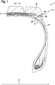
- a tire 1 according to the invention is shown schematically in a radial sectional view.
- the tire 1 can be rotated about an axis of rotation 2 in a direction of rotation 3.
- Tire 1 has a tire belt package 4 and a shoulder pad 5, the shoulder pad 5 being arranged in a shoulder region 6 of the tire 1.
- the tire 1 also has an electromagnetic transmitting and receiving device 7.
- the electromagnetic transmitting and receiving device 7 is arranged in the shoulder region 6 in such a way that it has a maximum distance 20 of at most 2 mm from the shoulder pad 5.
- the electromagnetic transmitting and receiving device 7 is arranged in the shoulder region 6 in such a way that it has a maximum distance 20 of at most 0.1 mm to at most 2 mm from the shoulder pad 5.
- the electromagnetic transmitting and receiving device 7 has a rubber jacket 21.
- the rubber jacket 21 is in particular a component of the electromagnetic transmitting and receiving device 7.
- Inside the rubber jacket 21 are electrical and electronic components 22 of the electromagnetic transmitting and receiving device 7 arranged.
- the electrical and electronic components 22 and the rubber casing 21 form the electromagnetic transmitting and receiving device 7.
- an inventive tire 1 according to one embodiment is shown schematically in a radial sectional view.
- the electromagnetic transmitting and receiving device 7 is arranged in the shoulder region 6 in such a way that it is in direct contact with the shoulder pad 5.
- an inventive tire 1 according to one embodiment is shown schematically in a radial sectional view.
- the tire belt package 4 has an axial end point 8.
- the axial end point 8 is starting from a tire center plane 9 in a direction 10, the direction 10 being parallel to the axis of rotation 2, the point of the tire belt package 4 that is furthest from the tire center plane 9.
- the tire center plane 9 is a plane of symmetry of the tire 1.
- the axis of rotation 2 is perpendicular to the tire center plane 9.
- the shoulder pad 5 has a first surface point 14, which of all surface points of the shoulder pad 5 is closest to the axis of rotation 2 in a radial direction 15.
- a radial distance 16 of a first surface point 17 of the electromagnetic transmitting and receiving device 7, which is closest to the axis of rotation 2 in the radial direction 15, to the axis of rotation 2 is at least 3 mm greater than a radial distance 18 of the first surface point 14 of the shoulder pad 5 to the axis of rotation 2.
- a radial distance 19 between the axial end point 8 and the axis of rotation 2 is at least 3 mm greater than the radial distance 16 between the first surface point 17 of the electromagnetic transmitting and receiving device 7 and the axis of rotation 2.
Landscapes
- Engineering & Computer Science (AREA)
- Computer Hardware Design (AREA)
- Microelectronics & Electronic Packaging (AREA)
- Physics & Mathematics (AREA)
- General Physics & Mathematics (AREA)
- Theoretical Computer Science (AREA)
- Mechanical Engineering (AREA)
- Tires In General (AREA)
Abstract
Description
- Die Erfindung bezieht sich auf einen Reifen.
- Die Erfindung geht aus von einem Reifen, wobei der Reifen um eine Rotationsachse in eine Umlaufrichtung rotierbar ist. Der Reifen weist ein Reifengürtelpaket und ein Schulterpolster auf. Das Schulterpolster ist in einem Schulterbereich des Reifens angeordnet. Der Reifen weist ferner eine elektromagnetische Sende- und Empfangsvorrichtung auf.
- Bei der elektromagnetischen Sende- und Empfangsvorrichtung handelt es sich insbesondere um eine RFID-Vorrichtung. RFID steht für Radio Frequency Identification und bedeutet Identifizierung mit Hilfe elektromagnetischer Wellen.
- Aus dem Stand der Technik sind Reifen bekannt die elektromagnetische Sende- und Empfangsvorrichtungen aufweisen. Beispielsweise wird in der
EP2223814B1 eine elektromagnetische Sende- und Empfangsvorrichtung für einen Reifen offenbart. - Bei den aus dem Stand der Technik bekannten Reifen könnte eine Anordnung einer elektromagnetischen Sende- und Empfangsvorrichtung innerhalb des Reifens nicht optimal ausgestaltet sein. So könnte die elektromagnetische Sende- und Empfangsvorrichtung in einem solchen Bereich des Reifens angeordnet sein, in dem sie höheren mechanischen Belastungen ausgesetzt sein könnte als in anderen Bereichen des Reifens.
- Der Erfindung liegt daher die Aufgabe zugrunde einen Reifen bereitzustellen, bei dem die Anordnung der elektromagnetischen Sende- und Empfangsvorrichtung innerhalb des Reifens verbessert wird.
- Gelöst wird die erfindungsgemäße Aufgabe dadurch, dass die elektromagnetische Sende- und Empfangsvorrichtung derart in dem Schulterbereich angeordnet ist, dass sie einen maximalen Abstand von höchstens 2 mm zu dem Schulterpolster aufweist.
- Durch den erfindungsgemäßen Umstand, wonach die elektromagnetische Sende- und Empfangsvorrichtung derart in dem Schulterbereich angeordnet ist, dass sie einen maximalen Abstand von höchstens 2 mm zu dem Schulterpolster aufweist, wird die elektromagnetische Sende- und Empfangsvorrichtung in einem solchen Bereich des Reifens angeordnet, in dem sie in einer ausreichenden räumlichen Nähe zu dem Schulterpolster des Reifens angeordnet ist. Durch diese Nähe zu dem Schulterpolster kann die elektromagnetische Sende- und Empfangsvorrichtung vor mechanischen Belastungen besser geschützt werden, als es in anderen Bereichen des Reifens der Fall wäre.
- Somit wird ein verbesserter Reifen bereitgestellt.
- Bei dem Reifen handelt es sich insbesondere um einen Lkw-Reifen, um einen Pkw-Reifen oder um einen Fahrrad-Reifen oder um einen Motorrad-Reifen.
- Weitere vorteilhafte Ausgestaltungsformen der vorliegenden Erfindung sind Gegenstand der Unteransprüche.
- Gemäß einer vorzugsweisen Ausgestaltungsform der vorliegenden Erfindung ist die elektromagnetische Sende- und Empfangsvorrichtung derart in dem Schulterbereich angeordnet, dass sie einen maximalen Abstand von höchstens 0,1 mm bis höchstens 2 mm zu dem Schulterpolster aufweist.
- Gemäß einer nächsten vorzugsweisen Ausgestaltungsform der vorliegenden Erfindung ist die elektromagnetische Sende- und Empfangsvorrichtung derart in dem Schulterbereich angeordnet, dass sie in einem direkten Kontakt mit dem Schulterpolster steht.
- Durch den erfindungsgemäßen Umstand, wonach die elektromagnetische Sende- und Empfangsvorrichtung derart in dem Schulterbereich angeordnet ist, dass sie in einem direkten Kontakt mit dem Schulterpolster steht, wird eine Positionierung der elektromagnetischen Sende- und Empfangsvorrichtung erreicht, die zu einem verbesserten Sende- und Empfangsverhalten der elektromagnetischen Sende- und Empfangsvorrichtung führt. Hintergrund dieses verbesserten Sende- und Empfangsverhaltens ist, dass ein Abstand der elektromagnetischen Sende- und Empfangsvorrichtung zu einer Felge, auf der ein Reifen montiert ist, in dem die elektromagnetische Sende- und Empfangsvorrichtung angeorndet ist, größer ist, als der Abstand der elektromagnetischen Sende- und Empfangsvorrichtung zu der Felge, wenn die elektromagnetische Sende- und Empfangsvorrichtung beispielsweise in einem Wulstbereich des Reifens angeordnet wäre.
- Gemäß einer nächsten vorzugsweisen Ausgestaltungsform der vorliegenden Erfindung ist die elektromagnetische Sende- und Empfangsvorrichtung vollständig innerhalb des Schulterpolsters angeordnet.
- Durch den erfindungsgemäßen Umstand, wonach die elektromagnetische Sende- und Empfangsvorrichtung vollständig innerhalb des Schulterpolsters angeordnet ist, wird eine robuste Positionierung der elektromagnetischen Sende- und Empfangsvorrichtung erreicht.
- Gemäß einer nächsten vorzugsweisen Ausgestaltungsform der vorliegenden Erfindung weist der Reifen ein Seitanwandbauteil auf, wobei das Seitenwandbauteil neben dem Schulterpolster angeordnet ist und wobei die elektromagnetische Sende- und Empfangsvorrichtung räumlich zwischen dem Schulterpolster und dem Seitenwandbauteil angeordnet ist.
- Durch den erfindungsgemäßen Umstand, wonach der Reifen ein Seitanwandbauteil aufweist, wobei das Seitenwandbauteil neben dem Schulterpolster angeordnet ist und wobei die elektromagnetische Sende- und Empfangsvorrichtung räumlich zwischen dem Schulterpolster und dem Seitenwandbauteil angeordnet ist, wird eine Positionierung der elektromagnetischen Sende- und Empfangsvorrichtung erreicht, die zu einem verbesserten Sende- und Empfangsverhalten der elektromagnetischen Sende- und Empfangsvorrichtung führt. Hintergrund dieses verbesserten Sende- und Empfangsverhaltens ist der optimale Abstand der elektromagnetischen Sende- und Empfangsvorrichtung zu einer Felge, auf der ein Reifen montiert ist, in dem die elektromagnetische Sende- und Empfangsvorrichtung angeordnet ist.
- Gemäß einer nächsten vorzugsweisen Ausgestaltungsform der vorliegenden Erfindung weist der Reifen einen Laufstreifen auf, wobei der Laufstreifen neben dem Schulterpolster angeordnet ist und wobei die elektromagnetische Sende- und Empfangsvorrichtung räumlich zwischen dem Schulterpolster und dem Laufstreifen angeordnet ist.
- Durch den erfindungsgemäßen Umstand, wonach der Reifen einen Laufstreifen aufweist, wobei der Laufstreifen neben dem Schulterpolster angeordnet ist und wobei die elektromagnetische Sende- und Empfangsvorrichtung räumlich zwischen dem Schulterpolster und dem Laufstreifen angeordnet ist, wird eine robuste Positionierung der elektromagnetischen Sende- und Empfangsvorrichtung erreicht.
- Gemäß einer nächsten vorzugsweisen Ausgestaltungsform der vorliegenden Erfindung weist das Reifengürtelpaket einen axialen Endpunkt auf, wobei der axiale Endpunkt ausgehend von einer Reifenmittenebene in eine Richtung, wobei die Richtung parallel zu der Rotationsachse liegt, der am weitesten von der Reifenmittenebene entfernt liegende Punkt des Reifengürtelpakets ist, und wobei das Schulterpolster einen ersten Oberflächenpunkt aufweist der von allen Oberflächenpunkten des Schulterpolsters in einer radialen Richtung der Rotationsachse am nächsten liegt, wobei ein radialer Abstand eines ersten Oberflächenpunktes der elektromagnetischen Sende- und Empfangsvorrichtung, der zur Rotationsachse in radialer Richtung nächstgelegen ist, zu der Rotationsachse mindestens 3 mm größer ist als ein radialer Abstand des ersten Oberflächenpunktes des Schulterpolsters zur Rotationsachse, und, dass ein radialer Abstand des axialen Endpunktes zu der Rotationsachse mindestens 3 mm größer ist, als der radiale Abstand des ersten Oberflächenpunktes der elektromagnetischen Sende- und Empfangsvorrichtung zu der Rotationsachse.
- Durch den erfindungsgemäßen Umstand, wonach das Reifengürtelpaket einen axialen Endpunkt aufweist, wobei der axiale Endpunkt ausgehend von einer Reifenmittenebene in eine Richtung, wobei die Richtung parallel zu der Rotationsachse liegt, der am weitesten von der Reifenmittenebene entfernt liegende Punkt des Reifengürtelpakets ist, und wobei das Schulterpolster einen ersten Oberflächenpunkt aufweist der von allen Oberflächenpunkten des Schulterpolsters in einer radialen Richtung der Rotationsachse am nächsten liegt, wobei ein radialer Abstand eines ersten Oberflächenpunktes der elektromagnetischen Sende- und Empfangsvorrichtung, der zur Rotationsachse in radialer Richtung nächstgelegen ist, zu der Rotationsachse mindestens 3 mm größer ist als ein radialer Abstand des ersten Oberflächenpunktes des Schulterpolsters zur Rotationsachse, und, dass ein radialer Abstand des axialen Endpunktes des Reifengürtelpakets zu der Rotationsachse mindestens 3 mm größer ist, als der radiale Abstand des ersten Oberflächenpunktes der elektromagnetischen Sende- und Empfangsvorrichtung zu der Rotationsachse, werden mechanische Belastungen an einer Kante des Reifengürtelpakets und am Ende des Schulterpolsters vermieden.
- Der Reifen folgt grundsätzlich einer Form eines Kreises. Ein radialer Abstand oder eine radiale Richtung erstrecken sich parallel zu einem Radius des Kreises dessen Form der Reifen grundsätzlich folgt. Der Radius liegt rechtwinklig zur Rotationsachse und zur Umlaufrichtung. Ein radialer Abstand ist stets ein Abstand bis zur Rotationsachse.
- Gemäß einer nächsten vorzugsweisen Ausgestaltungsform der vorliegenden Erfindung weist die elektromagnetische Sende- und Empfangsvorrichtung eine Gummiummantelung auf. Dabei ist die Gummiummantelung insbesondere Bestandteil der elektromagnetischen Sende- und Empfangsvorrichtung.
- Innerhalb der Gummiummantelung sind elektronische und elektrische Komponenten der elektromagnetischen Sende- und Empfangsvorrichtung angeordnet. Der erste Oberflächenpunkt der elektromagnetischen Sende- und Empfangsvorrichtung liegt dann auf der Oberfläche der Gummiummantelung. Die Oberfläche der Gummiummantelung ist eine von der elektromagnetischen Sende- und Empfangsvorrichtung weg orientierte Außenfläche. Die Gummiummantelung ist insbesondere quaderförmig oder ellipsoid ausgebildet, wobei insbesondere eine maximale Dicke der elektromagnetischen Sende- und Empfangsvorrichtung von 2 mm, eine dazu rechtwinklig sich erstreckende maximale Länge der elektromagnetischen Sende- und Empfangsvorrichtung von 80 mm und eine sich zu Dicke und Länge rechtwinklig sich erstreckende maximale Breite der elektromagnetischen Sende- und Empfangsvorrichtung von 20 mm nicht überschritten wird. Die elektronischen und elektrischen Komponenten der elektromagnetischen Sende- und Empfangsvorrichtung weisen insbesondere zusammen eine maximale räumliche Erstreckung von höchstens 70 mm auf. Die Antenne oder die Antennen der elektromagnetischen Sende- und Empfangsvorrichtung weist beziehungsweise weisen insbesondere für den Fall, wonach die Antenne beziehungsweise die Antennen einer Helixform folgt beziehungsweise folgen, einen Außendurchmesser von höchstens 2 mm auf.
- Die elektromagnetische Sende- und Empfangsvorrichtung weist gemäß einer vorteilhaften Ausfuhrungsform der Erfindung insbesondere eine separate Gummiummantelung auf.
- Die elektromagnetische Sende- und Empfangsvorrichtung weist gemäß einer vorteilhaften Ausfiihrungsform der Erfindung insbesondere eine oder zwei Antennen auf. Die Antenne beziehungsweise die zwei Antennen sind insbesondere helixförmig.
- Weitere Merkmale, Vorteile und Einzelheiten, auf die die Erfindung in ihrem Umfang aber nicht beschränkt ist, werden nun anhand der Zeichnungen näher beschrieben.
- Es zeigt:
-
Fig. 1 : Eine schematische Darstellung eines erfindungsgemäßen Reifens gemäß einer Ausführungsform in Radialschnittansicht; -
Fig. 2 : Eine schematische Darstellung eines erfindungsgemäßen Reifens gemäß einer weiteren Ausführungsform in Radialschnittansicht; -
Fig. 3 : Eine schematische Darstellung eines erfindungsgemäßen Reifens gemäß einer weiteren Ausführungsform in Radialschnittansicht. - In der
Figur 1 ist ein erfindungsgemäßer Reifen 1 schematisch in Radialschnittansicht dargestellt. Der Reifen 1 ist um eine Rotationsachse 2 in eine Umlaufrichtung 3 rotierbar. - Reifen 1 weist ein Reifengürtelpaket 4 und ein Schulterpolster 5 auf, wobei das Schulterpolster 5 in einem Schulterbereich 6 des Reifens 1 angeordnet ist. Der Reifen 1 weist weiter eine elektromagnetische Sende- und Empfangsvorrichtung 7 auf.
- Die elektromagnetische Sende- und Empfangsvorrichtung 7 derart in dem Schulterbereich 6 angeordnet, dass sie einen maximalen Abstand 20 von höchstens 2 mm zu dem Schulterpolster 5 aufweist.
- Insbesondere ist die elektromagnetische Sende- und Empfangsvorrichtung 7 derart in dem Schulterbereich 6 angeordnet, dass sie einen maximalen Abstand 20 von höchstens 0,1 mm bis höchstens 2 mm zu dem Schulterpolster 5 aufweist.
- Gemäß der in der
Figur 1 dargestellten Ausführungsform des erfindungsgemäßen Reifens 1 weist die elektromagnetische Sende- und Empfangsvorrichtung 7 eine Gummiummantelung 21 auf. Die Gummiummantelung 21 ist insbesondere Bestandteil der elektromagnetischen Sende- und Empfangsvorrichtung 7. Innerhalb der Gummiummantelung 21 sind elektrische und elektronische Bestandteile 22 der elektromagnetischen Sende- und Empfangsvorrichtung 7 angeordnet. Die elektrischen und elektronischen Bestandteile 22 und die Gummiummantelung 21 bilden die elektromagnetische Sende- und Empfangsvorrichtung 7. - In der
Figur 2 ist ein erfindungsgemäßer Reifen 1 gemäß einer Ausführungsform schematisch in Radialschnittansicht dargestellt. Gemäß der in derFigur 2 dargestellten Ausführungsform ist die elektromagnetische Sende- und Empfangsvorrichtung 7 derart in dem Schulterbereich 6 angeordnet, dass sie in einem direkten Kontakt mit dem Schulterpolster 5 steht. - In der
Figur 3 ist ein erfindungsgemäßer Reifen 1 gemäß einer Ausführungsform schematisch in Radialschnittansicht dargestellt. Gemäß der in derFigur 3 dargestellten Ausführungsform weist das Reifengürtelpaket 4 einen axialen Endpunkt 8 auf. Der axiale Endpunkt 8 ist ausgehend von einer Reifenmittenebene 9 in eine Richtung 10, wobei die Richtung 10 parallel zu der Rotationsachse 2 liegt, der am weitesten von der Reifenmittenebene 9 entfernt liegende Punkt des Reifengürtelpakets 4. Die Reifenmittenebene 9 ist eine Symmetrieebene des Reifens 1. Die Rotationsachse 2 steht senkrecht zur Reifenmittenebene 9. - Das Schulterpolster 5 weist einen ersten Oberflächenpunkt 14 auf, der von allen Oberflächenpunkten des Schulterpolsters 5 in einer radialen Richtung 15 der Rotationsachse 2 am nächsten liegt. Ein radialer Abstand 16 eines ersten Oberflächenpunktes 17 der elektromagnetischen Sende- und Empfangsvorrichtung 7, der zur Rotationsachse 2 in radialer Richtung 15 nächstgelegen ist, zu der Rotationsachse 2 ist mindestens 3 mm größer als ein radialer Abstand 18 des ersten Oberflächenpunktes 14 des Schulterpolsters 5 zur Rotationsachse 2. Dazu ist ein radialer Abstand 19 des axialen Endpunktes 8 zu der Rotationsachse 2 mindestens 3 mm größer, als der radiale Abstand 16 des ersten Oberflächenpunktes 17 der elektromagnetischen Sende- und Empfangsvorrichtung 7 zu der Rotationsachse 2.
-
- 1
- Reifen
- 2
- Rotationsachse
- 3
- Umlaufrichtung
- 4
- Reifengürtelpaket
- 5
- Schulterpolster
- 6
- Schulterbereich
- 7
- Elektromagnetische Sende- und Empfangsvorrichtung
- 8
- Axialer Endpunkt des Reifengürtelpakets
- 9
- Reifenmittenebene
- 10
- Richtung parallel zu der Rotationsachse
- 11
- Seitenwandbauteil
- 12
- Laufstreifen
- 13
- (als Bezugszeichen nicht verwendet)
- 14
- Erster Oberflächenpunkt des Schulterpolsters
- 15
- Radiale Richtung
- 16
- Radialer Abstand des ersten Oberflächenpunktes der elektromagnetischen Sende- und Empfangsvorrichtung zu der Rotationsachse
- 17
- Erster Oberflächenpunkt der elektromagnetischen Sende- und Empfangsvorrichtung
- 18
- Radialer Abstand des ersten Oberflächenpunktes des Schulterpolsters zur Rotationsachse
- 19
- Radialer Abstand des axialen Endpunktes zu der Rotationsachse
- 20
- Maximaler Abstand
- 21
- Gummiummantelung
- 22
- Elektrische und elektronische Bestandteile der elektromagnetischen Sende- und Empfangsvorrichtung
Claims (8)
- Reifen (1), wobei der Reifen (1) um eine Rotationsachse (2) in eine Umlaufrichtung (3) rotierbar ist, aufweisend ein Reifengürtelpaket (4) und ein Schulterpolster (5), wobei das Schulterpolster (5) in einem Schulterbereich (6) des Reifens (1) angeordnet ist, und aufweisend eine elektromagnetische Sende- und Empfangsvorrichtung (7), dadurch gekennzeichnet, dass die elektromagnetische Sende- und Empfangsvorrichtung (7) derart in dem Schulterbereich (6) angeordnet ist, dass sie einen maximalen Abstand (20) von höchstens 2 mm zu dem Schulterpolster (5) aufweist.
- Reifen (1) nach Anspruch 1, dadurch gekennzeichnet, dass die elektromagnetische Sende- und Empfangsvorrichtung (7) derart in dem Schulterbereich (6) angeordnet ist, dass sie einen maximalen Abstand (20) von höchstens 0,1 mm bis höchstens 2 mm zu dem Schulterpolster (5) aufweist.
- Reifen (1) nach Anspruch 1, dadurch gekennzeichnet, dass die elektromagnetische Sende- und Empfangsvorrichtung (7) derart in dem Schulterbereich (6) angeordnet ist, dass sie in einem direkten Kontakt mit dem Schulterpolster (5) steht.
- Reifen (1) nach Anspruch 1, dadurch gekennzeichnet, dass die elektromagnetische Sende- und Empfangsvorrichtung (7) vollständig innerhalb des Schulterpolsters (5) angeordnet ist.
- Reifen (1) nach Anspruch 1, dadurch gekennzeichnet, dass der Reifen (1) ein Seitanwandbauteil (11) aufweist, wobei das Seitenwandbauteil (11) neben dem Schulterpolster (5) angeordnet ist und wobei die elektromagnetische Sende- und Empfangsvorrichtung (7) räumlich zwischen dem Schulterpolster (5) und dem Seitenwandbauteil (11) angeordnet ist.
- Reifen (1) nach Anspruch 1, dadurch gekennzeichnet, dass der Reifen (1) einen Laufstreifen (12) aufweist, wobei der Laufstreifen (12) neben dem Schulterpolster (5) angeordnet ist und wobei die elektromagnetische Sende- und Empfangsvorrichtung (7) räumlich zwischen dem Schulterpolster (5) und dem Laufstreifen (12) angeordnet ist.
- Reifen (1) nach einem der vorhergehenden Ansprüche, dadurch gekennzeichnet, dass das Reifengürtelpaket (4) einen axialen Endpunkt (8) aufweist, wobei der axiale Endpunkt (8) ausgehend von einer Reifenmittenebene (9) in eine Richtung (10), wobei die Richtung (10) parallel zu der Rotationsachse (2) liegt, der am weitesten von der Reifenmittenebene (9) entfernt liegende Punkt des Reifengürtelpakets (4) ist, und wobei das Schulterpolster (5) einen ersten Oberflächenpunkt (14) aufweist der von allen Oberflächenpunkten des Schulterpolsters (5) in einer radialen Richtung (15) der Rotationsachse (2) am nächsten liegt, wobei ein radialer Abstand (16) eines ersten Oberflächenpunktes (17) der elektromagnetischen Sende- und Empfangsvorrichtung (7), der zur Rotationsachse (2) in radialer Richtung (15) nächstgelegen ist, zu der Rotationsachse (2) mindestens 3 mm größer ist als ein radialer Abstand (18) des ersten Oberflächenpunktes (14) des Schulterpolsters (5) zur Rotationsachse (2), und, dass ein radialer Abstand (19) des axialen Endpunktes (8) zu der Rotationsachse (2) mindestens 3 mm größer ist, als der radiale Abstand (16) des ersten Oberflächenpunktes (17) der elektromagnetischen Sende- und Empfangsvorrichtung (7) zu der Rotationsachse (2).
- Reifen (1) nach einem der vorhergehenden Ansprüche, dadurch gekennzeichnet, dass die elektromagnetische Sende- und Empfangsvorrichtung (7) eine Gummiummantelung (21) aufweist, wobei die Gummiummantelung (21) insbesondere Bestandteil der elektromagnetischen Sende- und Empfangsvorrichtung (7) ist.
Applications Claiming Priority (1)
| Application Number | Priority Date | Filing Date | Title |
|---|---|---|---|
| DE102019207022.1A DE102019207022A1 (de) | 2019-05-15 | 2019-05-15 | Reifen |
Publications (2)
| Publication Number | Publication Date |
|---|---|
| EP3739519A1 true EP3739519A1 (de) | 2020-11-18 |
| EP3739519B1 EP3739519B1 (de) | 2022-02-16 |
Family
ID=69844629
Family Applications (1)
| Application Number | Title | Priority Date | Filing Date |
|---|---|---|---|
| EP20163229.6A Active EP3739519B1 (de) | 2019-05-15 | 2020-03-16 | Reifen |
Country Status (2)
| Country | Link |
|---|---|
| EP (1) | EP3739519B1 (de) |
| DE (1) | DE102019207022A1 (de) |
Cited By (1)
| Publication number | Priority date | Publication date | Assignee | Title |
|---|---|---|---|---|
| CN117545641A (zh) * | 2021-06-30 | 2024-02-09 | 株式会社普利司通 | 轮胎、翻新轮胎和翻新轮胎生产方法 |
Citations (2)
| Publication number | Priority date | Publication date | Assignee | Title |
|---|---|---|---|---|
| US4911217A (en) * | 1989-03-24 | 1990-03-27 | The Goodyear Tire & Rubber Company | Integrated circuit transponder in a pneumatic tire for tire identification |
| EP2223814B1 (de) | 2009-02-25 | 2017-05-17 | The Goodyear Tire & Rubber Company | Umgebungsbeständige Anordnung mit einer elektronischen Vorrichtung zur Verwendung in einem Reifen |
-
2019
- 2019-05-15 DE DE102019207022.1A patent/DE102019207022A1/de not_active Withdrawn
-
2020
- 2020-03-16 EP EP20163229.6A patent/EP3739519B1/de active Active
Patent Citations (2)
| Publication number | Priority date | Publication date | Assignee | Title |
|---|---|---|---|---|
| US4911217A (en) * | 1989-03-24 | 1990-03-27 | The Goodyear Tire & Rubber Company | Integrated circuit transponder in a pneumatic tire for tire identification |
| EP2223814B1 (de) | 2009-02-25 | 2017-05-17 | The Goodyear Tire & Rubber Company | Umgebungsbeständige Anordnung mit einer elektronischen Vorrichtung zur Verwendung in einem Reifen |
Cited By (3)
| Publication number | Priority date | Publication date | Assignee | Title |
|---|---|---|---|---|
| CN117545641A (zh) * | 2021-06-30 | 2024-02-09 | 株式会社普利司通 | 轮胎、翻新轮胎和翻新轮胎生产方法 |
| EP4364970A4 (de) * | 2021-06-30 | 2024-11-13 | Bridgestone Corporation | Reifen, runderneuerter reifen und herstellungsverfahren für runderneuerten reifen |
| US12420597B2 (en) | 2021-06-30 | 2025-09-23 | Bridgestone Corporation | Tire, retreaded tire, and retreaded tire production method |
Also Published As
| Publication number | Publication date |
|---|---|
| EP3739519B1 (de) | 2022-02-16 |
| DE102019207022A1 (de) | 2020-11-19 |
Similar Documents
| Publication | Publication Date | Title |
|---|---|---|
| EP1366931B1 (de) | Transponder zum Einbau in oder auf die Oberfläche von Gegenständen | |
| EP3887176B1 (de) | Fahrzeugreifen | |
| EP3760456A1 (de) | Reifen | |
| EP3578395B1 (de) | Elektromagnetische sende- und empfangsvorrichtung | |
| EP3798020B1 (de) | Reifen | |
| EP3739519B1 (de) | Reifen | |
| EP3969297B1 (de) | Reifen | |
| EP2772986B1 (de) | Kraftfahrzeugtürgriff mit Antennenanordnung | |
| EP3740387B1 (de) | Verfahren zur herstellung eines transponders für einen fahrzeugreifen | |
| DE102019207021A1 (de) | Reifen | |
| WO2018224193A1 (de) | Elektromagnetische sende- und empfangsvorrichtung für einen reifen | |
| EP3953189B1 (de) | Reifen | |
| DE102011084592A1 (de) | Kombination eines Radar- und Antennenkopfes | |
| EP2618425A1 (de) | Antennenabdeckung | |
| DE102018100999A1 (de) | Vorrichtung zum positionsgerechten Befestigen einer Antennenanordnung | |
| EP3808577B1 (de) | Reifen | |
| DE202012012609U1 (de) | Antennenanordnung mit flachbauendem Antennenelement | |
| EP3281258A1 (de) | Elektronisches steuergerät | |
| DE102020124420A1 (de) | Antennenkuppel zum Schutz gegenüber Witterungseinflüssen | |
| EP3849826B1 (de) | Reifen mit seitenwandabriebsindikator | |
| EP1894269B1 (de) | Antennenanordnung | |
| DE102018200104A1 (de) | Sicherheitssystem | |
| DE102018209160A1 (de) | Elektromagnetische Sende- und Empfangsvorrichtung | |
| DE102010006010A1 (de) | IC-Gehäuse | |
| DE202018002096U1 (de) | Controlled Radiation Pattern Antenne |
Legal Events
| Date | Code | Title | Description |
|---|---|---|---|
| PUAI | Public reference made under article 153(3) epc to a published international application that has entered the european phase |
Free format text: ORIGINAL CODE: 0009012 |
|
| STAA | Information on the status of an ep patent application or granted ep patent |
Free format text: STATUS: THE APPLICATION HAS BEEN PUBLISHED |
|
| AK | Designated contracting states |
Kind code of ref document: A1 Designated state(s): AL AT BE BG CH CY CZ DE DK EE ES FI FR GB GR HR HU IE IS IT LI LT LU LV MC MK MT NL NO PL PT RO RS SE SI SK SM TR |
|
| AX | Request for extension of the european patent |
Extension state: BA ME |
|
| RAP1 | Party data changed (applicant data changed or rights of an application transferred) |
Owner name: CONTINENTAL REIFEN DEUTSCHLAND GMBH |
|
| STAA | Information on the status of an ep patent application or granted ep patent |
Free format text: STATUS: REQUEST FOR EXAMINATION WAS MADE |
|
| 17P | Request for examination filed |
Effective date: 20210518 |
|
| RBV | Designated contracting states (corrected) |
Designated state(s): AL AT BE BG CH CY CZ DE DK EE ES FI FR GB GR HR HU IE IS IT LI LT LU LV MC MK MT NL NO PL PT RO RS SE SI SK SM TR |
|
| RIC1 | Information provided on ipc code assigned before grant |
Ipc: B60C 9/18 20060101ALI20210915BHEP Ipc: B29D 30/00 20060101ALI20210915BHEP Ipc: G06K 19/077 20060101AFI20210915BHEP |
|
| GRAP | Despatch of communication of intention to grant a patent |
Free format text: ORIGINAL CODE: EPIDOSNIGR1 |
|
| STAA | Information on the status of an ep patent application or granted ep patent |
Free format text: STATUS: GRANT OF PATENT IS INTENDED |
|
| INTG | Intention to grant announced |
Effective date: 20211022 |
|
| GRAS | Grant fee paid |
Free format text: ORIGINAL CODE: EPIDOSNIGR3 |
|
| GRAA | (expected) grant |
Free format text: ORIGINAL CODE: 0009210 |
|
| STAA | Information on the status of an ep patent application or granted ep patent |
Free format text: STATUS: THE PATENT HAS BEEN GRANTED |
|
| AK | Designated contracting states |
Kind code of ref document: B1 Designated state(s): AL AT BE BG CH CY CZ DE DK EE ES FI FR GB GR HR HU IE IS IT LI LT LU LV MC MK MT NL NO PL PT RO RS SE SI SK SM TR |
|
| REG | Reference to a national code |
Ref country code: GB Ref legal event code: FG4D Free format text: NOT ENGLISH |
|
| REG | Reference to a national code |
Ref country code: CH Ref legal event code: EP |
|
| REG | Reference to a national code |
Ref country code: DE Ref legal event code: R096 Ref document number: 502020000638 Country of ref document: DE |
|
| REG | Reference to a national code |
Ref country code: AT Ref legal event code: REF Ref document number: 1469362 Country of ref document: AT Kind code of ref document: T Effective date: 20220315 |
|
| REG | Reference to a national code |
Ref country code: IE Ref legal event code: FG4D Free format text: LANGUAGE OF EP DOCUMENT: GERMAN |
|
| REG | Reference to a national code |
Ref country code: LT Ref legal event code: MG9D |
|
| REG | Reference to a national code |
Ref country code: NL Ref legal event code: MP Effective date: 20220216 |
|
| PG25 | Lapsed in a contracting state [announced via postgrant information from national office to epo] |
Ref country code: SE Free format text: LAPSE BECAUSE OF FAILURE TO SUBMIT A TRANSLATION OF THE DESCRIPTION OR TO PAY THE FEE WITHIN THE PRESCRIBED TIME-LIMIT Effective date: 20220216 Ref country code: RS Free format text: LAPSE BECAUSE OF FAILURE TO SUBMIT A TRANSLATION OF THE DESCRIPTION OR TO PAY THE FEE WITHIN THE PRESCRIBED TIME-LIMIT Effective date: 20220216 Ref country code: PT Free format text: LAPSE BECAUSE OF FAILURE TO SUBMIT A TRANSLATION OF THE DESCRIPTION OR TO PAY THE FEE WITHIN THE PRESCRIBED TIME-LIMIT Effective date: 20220616 Ref country code: NO Free format text: LAPSE BECAUSE OF FAILURE TO SUBMIT A TRANSLATION OF THE DESCRIPTION OR TO PAY THE FEE WITHIN THE PRESCRIBED TIME-LIMIT Effective date: 20220516 Ref country code: NL Free format text: LAPSE BECAUSE OF FAILURE TO SUBMIT A TRANSLATION OF THE DESCRIPTION OR TO PAY THE FEE WITHIN THE PRESCRIBED TIME-LIMIT Effective date: 20220216 Ref country code: LT Free format text: LAPSE BECAUSE OF FAILURE TO SUBMIT A TRANSLATION OF THE DESCRIPTION OR TO PAY THE FEE WITHIN THE PRESCRIBED TIME-LIMIT Effective date: 20220216 Ref country code: HR Free format text: LAPSE BECAUSE OF FAILURE TO SUBMIT A TRANSLATION OF THE DESCRIPTION OR TO PAY THE FEE WITHIN THE PRESCRIBED TIME-LIMIT Effective date: 20220216 Ref country code: ES Free format text: LAPSE BECAUSE OF FAILURE TO SUBMIT A TRANSLATION OF THE DESCRIPTION OR TO PAY THE FEE WITHIN THE PRESCRIBED TIME-LIMIT Effective date: 20220216 Ref country code: BG Free format text: LAPSE BECAUSE OF FAILURE TO SUBMIT A TRANSLATION OF THE DESCRIPTION OR TO PAY THE FEE WITHIN THE PRESCRIBED TIME-LIMIT Effective date: 20220516 |
|
| PG25 | Lapsed in a contracting state [announced via postgrant information from national office to epo] |
Ref country code: PL Free format text: LAPSE BECAUSE OF FAILURE TO SUBMIT A TRANSLATION OF THE DESCRIPTION OR TO PAY THE FEE WITHIN THE PRESCRIBED TIME-LIMIT Effective date: 20220216 Ref country code: LV Free format text: LAPSE BECAUSE OF FAILURE TO SUBMIT A TRANSLATION OF THE DESCRIPTION OR TO PAY THE FEE WITHIN THE PRESCRIBED TIME-LIMIT Effective date: 20220216 Ref country code: GR Free format text: LAPSE BECAUSE OF FAILURE TO SUBMIT A TRANSLATION OF THE DESCRIPTION OR TO PAY THE FEE WITHIN THE PRESCRIBED TIME-LIMIT Effective date: 20220517 Ref country code: FI Free format text: LAPSE BECAUSE OF FAILURE TO SUBMIT A TRANSLATION OF THE DESCRIPTION OR TO PAY THE FEE WITHIN THE PRESCRIBED TIME-LIMIT Effective date: 20220216 |
|
| PG25 | Lapsed in a contracting state [announced via postgrant information from national office to epo] |
Ref country code: IS Free format text: LAPSE BECAUSE OF FAILURE TO SUBMIT A TRANSLATION OF THE DESCRIPTION OR TO PAY THE FEE WITHIN THE PRESCRIBED TIME-LIMIT Effective date: 20220617 |
|
| PG25 | Lapsed in a contracting state [announced via postgrant information from national office to epo] |
Ref country code: SM Free format text: LAPSE BECAUSE OF FAILURE TO SUBMIT A TRANSLATION OF THE DESCRIPTION OR TO PAY THE FEE WITHIN THE PRESCRIBED TIME-LIMIT Effective date: 20220216 Ref country code: SK Free format text: LAPSE BECAUSE OF FAILURE TO SUBMIT A TRANSLATION OF THE DESCRIPTION OR TO PAY THE FEE WITHIN THE PRESCRIBED TIME-LIMIT Effective date: 20220216 Ref country code: RO Free format text: LAPSE BECAUSE OF FAILURE TO SUBMIT A TRANSLATION OF THE DESCRIPTION OR TO PAY THE FEE WITHIN THE PRESCRIBED TIME-LIMIT Effective date: 20220216 Ref country code: EE Free format text: LAPSE BECAUSE OF FAILURE TO SUBMIT A TRANSLATION OF THE DESCRIPTION OR TO PAY THE FEE WITHIN THE PRESCRIBED TIME-LIMIT Effective date: 20220216 Ref country code: DK Free format text: LAPSE BECAUSE OF FAILURE TO SUBMIT A TRANSLATION OF THE DESCRIPTION OR TO PAY THE FEE WITHIN THE PRESCRIBED TIME-LIMIT Effective date: 20220216 Ref country code: CZ Free format text: LAPSE BECAUSE OF FAILURE TO SUBMIT A TRANSLATION OF THE DESCRIPTION OR TO PAY THE FEE WITHIN THE PRESCRIBED TIME-LIMIT Effective date: 20220216 |
|
| REG | Reference to a national code |
Ref country code: DE Ref legal event code: R097 Ref document number: 502020000638 Country of ref document: DE |
|
| PG25 | Lapsed in a contracting state [announced via postgrant information from national office to epo] |
Ref country code: MC Free format text: LAPSE BECAUSE OF FAILURE TO SUBMIT A TRANSLATION OF THE DESCRIPTION OR TO PAY THE FEE WITHIN THE PRESCRIBED TIME-LIMIT Effective date: 20220216 Ref country code: AL Free format text: LAPSE BECAUSE OF FAILURE TO SUBMIT A TRANSLATION OF THE DESCRIPTION OR TO PAY THE FEE WITHIN THE PRESCRIBED TIME-LIMIT Effective date: 20220216 |
|
| REG | Reference to a national code |
Ref country code: BE Ref legal event code: MM Effective date: 20220331 |
|
| PLBE | No opposition filed within time limit |
Free format text: ORIGINAL CODE: 0009261 |
|
| STAA | Information on the status of an ep patent application or granted ep patent |
Free format text: STATUS: NO OPPOSITION FILED WITHIN TIME LIMIT |
|
| 26N | No opposition filed |
Effective date: 20221117 |
|
| PG25 | Lapsed in a contracting state [announced via postgrant information from national office to epo] |
Ref country code: LU Free format text: LAPSE BECAUSE OF NON-PAYMENT OF DUE FEES Effective date: 20220316 Ref country code: IE Free format text: LAPSE BECAUSE OF NON-PAYMENT OF DUE FEES Effective date: 20220316 |
|
| PG25 | Lapsed in a contracting state [announced via postgrant information from national office to epo] |
Ref country code: SI Free format text: LAPSE BECAUSE OF FAILURE TO SUBMIT A TRANSLATION OF THE DESCRIPTION OR TO PAY THE FEE WITHIN THE PRESCRIBED TIME-LIMIT Effective date: 20220216 Ref country code: BE Free format text: LAPSE BECAUSE OF NON-PAYMENT OF DUE FEES Effective date: 20220331 |
|
| PG25 | Lapsed in a contracting state [announced via postgrant information from national office to epo] |
Ref country code: IT Free format text: LAPSE BECAUSE OF FAILURE TO SUBMIT A TRANSLATION OF THE DESCRIPTION OR TO PAY THE FEE WITHIN THE PRESCRIBED TIME-LIMIT Effective date: 20220216 |
|
| REG | Reference to a national code |
Ref country code: CH Ref legal event code: PL |
|
| PG25 | Lapsed in a contracting state [announced via postgrant information from national office to epo] |
Ref country code: LI Free format text: LAPSE BECAUSE OF NON-PAYMENT OF DUE FEES Effective date: 20230331 Ref country code: CH Free format text: LAPSE BECAUSE OF NON-PAYMENT OF DUE FEES Effective date: 20230331 |
|
| REG | Reference to a national code |
Ref country code: DE Ref legal event code: R081 Ref document number: 502020000638 Country of ref document: DE Owner name: CONTINENTAL REIFEN DEUTSCHLAND GMBH, DE Free format text: FORMER OWNER: CONTINENTAL REIFEN DEUTSCHLAND GMBH, 30165 HANNOVER, DE |
|
| PG25 | Lapsed in a contracting state [announced via postgrant information from national office to epo] |
Ref country code: MK Free format text: LAPSE BECAUSE OF FAILURE TO SUBMIT A TRANSLATION OF THE DESCRIPTION OR TO PAY THE FEE WITHIN THE PRESCRIBED TIME-LIMIT Effective date: 20220216 Ref country code: CY Free format text: LAPSE BECAUSE OF FAILURE TO SUBMIT A TRANSLATION OF THE DESCRIPTION OR TO PAY THE FEE WITHIN THE PRESCRIBED TIME-LIMIT Effective date: 20220216 |
|
| PG25 | Lapsed in a contracting state [announced via postgrant information from national office to epo] |
Ref country code: HU Free format text: LAPSE BECAUSE OF FAILURE TO SUBMIT A TRANSLATION OF THE DESCRIPTION OR TO PAY THE FEE WITHIN THE PRESCRIBED TIME-LIMIT; INVALID AB INITIO Effective date: 20200316 |
|
| PG25 | Lapsed in a contracting state [announced via postgrant information from national office to epo] |
Ref country code: MT Free format text: LAPSE BECAUSE OF FAILURE TO SUBMIT A TRANSLATION OF THE DESCRIPTION OR TO PAY THE FEE WITHIN THE PRESCRIBED TIME-LIMIT Effective date: 20220216 |
|
| GBPC | Gb: european patent ceased through non-payment of renewal fee |
Effective date: 20240316 |
|
| PG25 | Lapsed in a contracting state [announced via postgrant information from national office to epo] |
Ref country code: GB Free format text: LAPSE BECAUSE OF NON-PAYMENT OF DUE FEES Effective date: 20240316 |
|
| PG25 | Lapsed in a contracting state [announced via postgrant information from national office to epo] |
Ref country code: GB Free format text: LAPSE BECAUSE OF NON-PAYMENT OF DUE FEES Effective date: 20240316 |
|
| PGFP | Annual fee paid to national office [announced via postgrant information from national office to epo] |
Ref country code: AT Payment date: 20250417 Year of fee payment: 5 |
|
| PG25 | Lapsed in a contracting state [announced via postgrant information from national office to epo] |
Ref country code: TR Free format text: LAPSE BECAUSE OF FAILURE TO SUBMIT A TRANSLATION OF THE DESCRIPTION OR TO PAY THE FEE WITHIN THE PRESCRIBED TIME-LIMIT Effective date: 20220216 |
|
| PGFP | Annual fee paid to national office [announced via postgrant information from national office to epo] |
Ref country code: DE Payment date: 20260331 Year of fee payment: 7 |
|
| PGFP | Annual fee paid to national office [announced via postgrant information from national office to epo] |
Ref country code: FR Payment date: 20260320 Year of fee payment: 7 |