EP3738528A1 - Ablösesystem für gefässverschlussvorrichtungen mit konischem kerndraht und einzelschleifensicherungsablösung - Google Patents
Ablösesystem für gefässverschlussvorrichtungen mit konischem kerndraht und einzelschleifensicherungsablösung Download PDFInfo
- Publication number
- EP3738528A1 EP3738528A1 EP20183939.6A EP20183939A EP3738528A1 EP 3738528 A1 EP3738528 A1 EP 3738528A1 EP 20183939 A EP20183939 A EP 20183939A EP 3738528 A1 EP3738528 A1 EP 3738528A1
- Authority
- EP
- European Patent Office
- Prior art keywords
- fuse element
- electrically conductive
- heating fuse
- corewire
- accordance
- Prior art date
- Legal status (The legal status is an assumption and is not a legal conclusion. Google has not performed a legal analysis and makes no representation as to the accuracy of the status listed.)
- Withdrawn
Links
Images


Classifications
-
- A—HUMAN NECESSITIES
- A61—MEDICAL OR VETERINARY SCIENCE; HYGIENE
- A61B—DIAGNOSIS; SURGERY; IDENTIFICATION
- A61B17/00—Surgical instruments, devices or methods, e.g. tourniquets
- A61B17/12—Surgical instruments, devices or methods, e.g. tourniquets for ligaturing or otherwise compressing tubular parts of the body, e.g. blood vessels, umbilical cord
- A61B17/12022—Occluding by internal devices, e.g. balloons or releasable wires
- A61B17/12099—Occluding by internal devices, e.g. balloons or releasable wires characterised by the location of the occluder
- A61B17/12109—Occluding by internal devices, e.g. balloons or releasable wires characterised by the location of the occluder in a blood vessel
-
- A—HUMAN NECESSITIES
- A61—MEDICAL OR VETERINARY SCIENCE; HYGIENE
- A61B—DIAGNOSIS; SURGERY; IDENTIFICATION
- A61B17/00—Surgical instruments, devices or methods, e.g. tourniquets
- A61B17/12—Surgical instruments, devices or methods, e.g. tourniquets for ligaturing or otherwise compressing tubular parts of the body, e.g. blood vessels, umbilical cord
- A61B17/12022—Occluding by internal devices, e.g. balloons or releasable wires
- A61B17/12099—Occluding by internal devices, e.g. balloons or releasable wires characterised by the location of the occluder
- A61B17/12109—Occluding by internal devices, e.g. balloons or releasable wires characterised by the location of the occluder in a blood vessel
- A61B17/12113—Occluding by internal devices, e.g. balloons or releasable wires characterised by the location of the occluder in a blood vessel within an aneurysm
-
- A—HUMAN NECESSITIES
- A61—MEDICAL OR VETERINARY SCIENCE; HYGIENE
- A61B—DIAGNOSIS; SURGERY; IDENTIFICATION
- A61B17/00—Surgical instruments, devices or methods, e.g. tourniquets
- A61B17/12—Surgical instruments, devices or methods, e.g. tourniquets for ligaturing or otherwise compressing tubular parts of the body, e.g. blood vessels, umbilical cord
- A61B17/12022—Occluding by internal devices, e.g. balloons or releasable wires
- A61B17/12131—Occluding by internal devices, e.g. balloons or releasable wires characterised by the type of occluding device
- A61B17/1214—Coils or wires
- A61B17/12145—Coils or wires having a pre-set deployed three-dimensional shape
-
- A—HUMAN NECESSITIES
- A61—MEDICAL OR VETERINARY SCIENCE; HYGIENE
- A61B—DIAGNOSIS; SURGERY; IDENTIFICATION
- A61B17/00—Surgical instruments, devices or methods, e.g. tourniquets
- A61B17/12—Surgical instruments, devices or methods, e.g. tourniquets for ligaturing or otherwise compressing tubular parts of the body, e.g. blood vessels, umbilical cord
- A61B17/12022—Occluding by internal devices, e.g. balloons or releasable wires
- A61B17/12131—Occluding by internal devices, e.g. balloons or releasable wires characterised by the type of occluding device
- A61B17/1214—Coils or wires
- A61B17/12154—Coils or wires having stretch limiting means
-
- A—HUMAN NECESSITIES
- A61—MEDICAL OR VETERINARY SCIENCE; HYGIENE
- A61B—DIAGNOSIS; SURGERY; IDENTIFICATION
- A61B17/00—Surgical instruments, devices or methods, e.g. tourniquets
- A61B2017/00535—Surgical instruments, devices or methods, e.g. tourniquets pneumatically or hydraulically operated
- A61B2017/00539—Surgical instruments, devices or methods, e.g. tourniquets pneumatically or hydraulically operated hydraulically
-
- A—HUMAN NECESSITIES
- A61—MEDICAL OR VETERINARY SCIENCE; HYGIENE
- A61B—DIAGNOSIS; SURGERY; IDENTIFICATION
- A61B17/00—Surgical instruments, devices or methods, e.g. tourniquets
- A61B2017/00831—Material properties
- A61B2017/00929—Material properties isolating electrical current
-
- A—HUMAN NECESSITIES
- A61—MEDICAL OR VETERINARY SCIENCE; HYGIENE
- A61B—DIAGNOSIS; SURGERY; IDENTIFICATION
- A61B17/00—Surgical instruments, devices or methods, e.g. tourniquets
- A61B17/12—Surgical instruments, devices or methods, e.g. tourniquets for ligaturing or otherwise compressing tubular parts of the body, e.g. blood vessels, umbilical cord
- A61B17/12022—Occluding by internal devices, e.g. balloons or releasable wires
- A61B2017/1205—Introduction devices
- A61B2017/12054—Details concerning the detachment of the occluding device from the introduction device
- A61B2017/12068—Details concerning the detachment of the occluding device from the introduction device detachable by heat
-
- A—HUMAN NECESSITIES
- A61—MEDICAL OR VETERINARY SCIENCE; HYGIENE
- A61B—DIAGNOSIS; SURGERY; IDENTIFICATION
- A61B17/00—Surgical instruments, devices or methods, e.g. tourniquets
- A61B17/12—Surgical instruments, devices or methods, e.g. tourniquets for ligaturing or otherwise compressing tubular parts of the body, e.g. blood vessels, umbilical cord
- A61B17/12022—Occluding by internal devices, e.g. balloons or releasable wires
- A61B2017/1205—Introduction devices
- A61B2017/12054—Details concerning the detachment of the occluding device from the introduction device
- A61B2017/1209—Details concerning the detachment of the occluding device from the introduction device detachable by electrical current or potential, e.g. electroactive polymer
Definitions
- the present invention relates to vasculature occlusive devices (e.g., embolic coils) for implantation within a blood vessel of a body.
- the present invention relates to an improved heating detachment system for an embolic coil delivery system in the treatment of blood vessel disorders.
- Vascular disorders and defects such as aneurysms and other arterio-venous malformations are especially difficult to treat when located near critical tissues or where ready access to malformation is not available. Both difficulty factors apply especially to cranial aneurysms. Due to the sensitive brain tissue surrounding cranial blood vessels and the restricted access, it is very challenging and often risky to surgically treat defects of the cranial vasculature.
- vasculature occlusion devices such as embolic coils
- catheter delivery systems In such systems used to treat cranial aneurysms, the distal end of an embolic coil delivery catheter is inserted into non-cranial vasculature of a patient, typically through a femoral artery in the groin, and guided to a predetermined delivery site within the cranium.
- embolic coils of various lengths generally approximately 1 cm to as long as approximately 100 cm, and preselected stiffness often are packed sequentially within a cranial aneurysm to limit blood flow therein and to encourage embolism formation.
- physicians first utilize stiffer coils to establish a framework within the aneurysm and then select more flexible coils to fill spaces within the framework.
- each coil conforms both to the aneurysm and to previously implanted coils.
- Each successive coil is selected individually based on factors including stiffness, length, and preformed shape which the coil will tend to assume after delivery.
- each embolic coil During implantation, the physician manipulates each embolic coil until it is in a satisfactory position, as seen by an imaging technique such as fluoroscopic visualization, before detaching the coil from the delivery system. It is beneficial for both ends of each coil to remain positioned within the aneurysm after delivery; otherwise, a length of coil protruding into the main lumen of the blood vessel invites undesired clotting external to the aneurysm. After each successive coil is detached, the next coil is subject to an increasing risk of becoming entangled in the growing mass of coils, thereby restricting the depth of insertion for that coil into the aneurysm.
- Difficulties may arise due to stretching of the embolic coils during repositioning or attempted retrieval of the coils, especially if the coil becomes entangled and complete insertion of the coil into the aneurysm is not accomplished. If pulling forces applied to a coil exceed its elastic limit, the coil will not return to its original shape. A stretched coil exhibits diminished pushability or retractability, and becomes more difficult to manipulate into an optimal position or to be removed. Moreover, a stretched coil occupies less volume than an unstretched coil, which increases the number of coils needed to sufficiently pack the aneurysm to encourage formation of a robust embolus positioned wholly within the aneurysm. To avoid such problems stretch resistance devices are used, such as that disclosed in US Patent No. 5,853,418 , herein incorporated by reference in its entirety, having a primary coil and an elongated stretch-resisting member fixedly attached to the primary coil in at least two locations.
- vaso-occlusive coils In order to deliver the vaso-occlusive coils to a desired site, e.g., an aneurysm, in the vasculature, it is well-known to first position a relatively small profile, delivery catheter or micro-catheter at the targeted site using fluoroscopy, ultrasound, or other method of steerable navigation. A delivery or "pusher" wire is then passed through a proximal end of the catheter lumen, until a vaso-occlusive coil coupled to a distal end of the pusher wire is extended out of the distal end opening of the catheter and into the blood vessel at the targeted site.
- vaso-occlusive device is then released or detached from the end pusher wire, and the pusher wire is withdrawn in a proximal direction back through the catheter.
- another occlusive device may then be pushed through the catheter and released at the same site in a similar manner.
- an electrolytically severable junction which is an exposed section or detachment zone located along a distal end portion of the pusher wire.
- the detachment zone is typically made of stainless steel and is located just proximal of the vaso-occlusive device.
- An electrolytically severable junction is susceptible to electrolysis and disintegrates when the pusher wire is electrically charged in the presence of an ionic solution, such as blood or other bodily fluids.
- a current applied to the conductive pusher wire completes a circuit with an electrode attached to the patient's skin, or with a conductive needle inserted through the skin at a remote site, and the detachment zone disintegrates due to electrolysis.
- Another conventional detachment technique during delivery of a vaso-occlusive device involves the use of fluid pressure (e.g., hydraulic detachment) to release an embolic coil once it is properly positioned, as described in US Patent Nos. 6,063,100 and 6,179,857 , each of which is herein incorporated by reference in their entirety.
- fluid pressure e.g., hydraulic detachment
- the main problems associated with current detachment schemes are reliability of detachment, speed of detachment, convenience of detaching mechanism (e.g., hydraulic detachment requires a high pressure syringe, while electrolytic detachment requires a battery operated box), and length/stiffness of the distal section.
- vaso-occlusive device e.g., an embolic coil device
- An aspect of the present invention relates to an improved heating detachment system for delivery of a vaso-occlusive device that is simpler, more reliable, quicker, more convenient and having a reduced length rigid distal section than that of conventional mechanical detachment systems.
- Another aspect of the present invention is directed to an improved detachment system for delivery of a vaso-occlusive device that optimizes distal flexibility, placement at a desired treatment site and detachment characteristics.
- Still another aspect of the present invention relates to a vasculature occlusion device detachment system
- a heating fuse element having a predetermined resistivity, a first terminating end and an opposite second terminating end.
- the heating fuse element is made of a material that melts when a current is applied that exceeds a predetermined maximum current threshold.
- the system further includes an electrically conductive corewire electrically connected proximate its distal end directly to the first terminating end of the heating fuse element at a first electrical connection joint.
- An insulated electrically conductive wire separate from the electrically conductive corewire is electrically connected directly to the second terminating end of the heating fuse element at a second electrical connection joint.
- An inner insulation sleeve made from an electrical non-conductive material is placed over a distal section of the corewire and covers the first electrical connection joint.
- the inner insulation sleeve is disposed between the insulated electrically conductive wire and the electrically conductive corewire.
- An outer insulation sleeve made from an electrical non-conductive material is disposed over a distal section of an assembly including the insulated electrically conductive wire, the inner insulation sleeve and the electrically conductive corewire.
- the outer insulation sleeve covers the second electrical connection joint.
- Yet another aspect of the present invention is directed to a method of using the vasculature occlusion device detachment system in the preceding paragraph.
- the first terminating end of the heating fuse element is electrically connected directly to the electrically conductive corewire proximate its distal end at the first electrical connection joint.
- the inner insulation sleeve is positioned over a distal section of the electrically conductive corewire and covering the first electrical connection joint.
- the second terminating end of the heating fuse element is threaded through the loop of the vasculature occlusion device.
- a second electrical connection joint is formed by electrically connecting the second terminating end of the heating fuse element to the insulated electrically conductive wire at the second electrical connection joint.
- the outer insulation sleeve is positioned over a distal section of the assembly and covering the second electrical connection joint.
- proximal and distal refer to a direction closer to or away from, respectively, an operator (e.g., surgeon, physician, nurse, technician, etc.) who would insert the medical device into the patient, with the tip-end (i.e., distal end or leading end) of the device inserted inside a patient's body.
- an operator e.g., surgeon, physician, nurse, technician, etc.
- tip-end i.e., distal end or leading end
- proximal direction would refer to the direction towards the operator
- distal direction would refer to the direction away from the operator towards the leading or tip-end of the medical device.
- the present inventive heating detachment system is utilized for delivery of an embolic component, e.g., embolic helical coil. It is, however, intended and within the scope of the present invention to use the present inventive heating detachment system with any type of vaso-occlusive device.
- FIG. 1A is a side view of an exemplary fuse heating detachment system in accordance with the present invention for delivery of a vaso-occlusive device, typically a helical embolic coil 5 formed by a series of loops/windings defining a coil lumen 25.
- a vaso-occlusive device typically a helical embolic coil 5 formed by a series of loops/windings defining a coil lumen 25.
- the present inventive detachment system is not limited to embolic coils, but instead is equally suited for any type or shape vaso-occlusive device.
- Embolic coil 5 has a proximal coil junction 10 located at its proximal end.
- Proximal coil junction 10 is a joint, preferably made out of at least one of an adhesive, an epoxy and/or a polymer.
- the joint made of adhesive, epoxy and/or polymer is of relatively low strength and/or relatively low durometer. That is, the relatively low strength of the epoxy/adhesive, or the relatively low durometer of the polymer used to fill that junction (which is related to its tear-out strength) is preferably less than the buckling strength of a delivery catheter used to implant the vaso-occlusive device in a blood vessel.
- a loop, ring or eyelet 35 extends in a proximal direction from the proximal coil junction 10 of the embolic coil 5. Preferably, only a single loop, ring or eyelet is provided on the embolic coil.
- a distal end of the embolic coil 5 is closed off by a distal bead 15.
- One or more stretch resistant (SR) members 20, e.g., suture filaments, disposed in the coil lumen 25 provide stretch resistance when excessive pulling forces are applied to the embolic coil 5 during implantation in a patient.
- SR stretch resistant
- each stretch resistant member 20 extends longitudinally the entire length of the coil lumen 25 secured at its respective ends by the proximal coil junction 10 and distal bead 15 to minimize excessive elongation.
- embolic coil 5 is advanced via a delivery catheter 80 to a target site in the body (e.g., within the blood vessel).
- a target site in the body e.g., within the blood vessel.
- Corewire 45 has a stiffer proximal section proximate its proximal end compared to its more flexible distal section proximate its distal end.
- flexibility of the corewire 45 needed to advance the delivery system through distal tortuosity may be achieved by grinding tapers over its distal section, wherein the length and/or number of tapers determines the flexibility of the distal section.
- the corewire is made from any biocompatible electrically conductive material such as stainless steel or Nitonal.
- Corewire 45 may be made either as an integrated single piece construction throughout or, alternatively, as a two-piece construction secured, attached, connected or mounted together.
- the proximal section of the corewire may be a first material (e.g., stainless steel), while the distal section connected to the proximal section may be made of a second material (e.g., Nitonal) different than the first material.
- a non-conductive coating (e.g., insulation sleeve) 55 is disposed about the exterior of the corewire 45. Attached, secured, connected or otherwise mounted to its outer surface and extending preferably the length of the corewire 45 is a separate insulated electrically conductive wire 60.
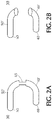
- a heating fuse element 30 having a given resistivity such as an electrical conductive wire or electrical conductive strip is preferably configured as a segment having two terminating ends.
- heating fuse element 30 is substantially U-shaped or hemispherical. Any other shape is contemplated and within the intended scope of the present invention so long as the heating fuse element 30 is configured as a segment having two terminating ends.
- heating fuse element 30 has a failure section 65 substantially midway between its terminating ends. Failure section 65 is a mechanically induced deformation and/or reduced diameter (e.g., thinner) cross-section to further increase the localized electrical resistance in this section of the heating fuse element thereby narrowing or targeting the location in which the heating fuse element melts and/or severs.
- One terminating end 40 of the heating fuse element 30 is electrically connected directly to the distal end of the corewire 45 forming a first electrical connection joint 70.
- An inner insulation sleeve 83 made of an electrically non-conductive material is placed over a distal section of the corewire disposed between the insulation sleeve 55 and electrically conductive wire 60.
- the inner insulation sleeve 83 protects the first electrical connection joint 70 while also preventing an electrical connection between the second terminating end 50 of the heating fuse element 30 and the corewire 45.
- the second terminating end 50 of the heating fuse element 30 is threaded through the loop 35 of the embolic coil 5.
- An electrical circuit is completed or closed by electrically connecting the second terminating end 50 of the heating fuse element 30 directly to a stripped distal end of the insulated electrical wire 60 forming a second electrical connection joint 75.
- An outer insulation sleeve 85 also made of an electrically non-conductive material, is placed over at least a portion of the insulated conductive wire 60, the inner insulation sleeve 83 and the corewire 45. The outer insulation sleeve 85 secures the second electrical connection joint 75 to the insulated conductive wire 60 while protecting the second electrical connection joint 75 itself. Either the same or different electrically non-conductive materials may be used for the inner and outer insulation sleeves 83, 85.
- a power supply 90 e.g., a battery
- the conductors i.e., proximal ends of corewire 45 and insulated electrically conductive wire 60
- Each of the first and second electrical connection joints 70, 75 may be established via solder, welding, conductive epoxy or any other electrical joint connection.
- the first terminating end 40 of the heating fuse element 30 is electrically connected to the corewire 45 proximate its distal end thereby forming the first electrical joint 70.
- Inner insulation sleeve 83 is positioned over a distal section of the electrically conductive corewire 45 while also covering the first electrical connection joint 70.
- the second terminating end of 50 of the heating fuse element 30 is then threaded through the loop 35 of the embolic coil 5. Once threaded through the loop 35, the second terminating end 50 of the heating fuse element 30 is electrically connected to the insulated electrically conductive wire 60 at the second electrical connection joint 75.
- the outer insulation sleeve 85 is positioned over a distal section of the assembly (including the insulated electrically conductive wire 60, the inner insulation sleeve 83 and the electrically conductive corewire 45) and is also positioned to cover the second electrical connection joint 75.
- the vasculature occlusion device 5 is advanced via the delivery catheter 80 to a target site in a human body.
- electrical activation of the heating element 30 by the power source (e.g., a battery) 90 increases the electrical resistance therein. Due to its design, the resistance is greatest in the failure section 65 of the heating fuse element 30.
- the present inventive detachment system advantageously minimizes the length (as measured from approximately its midsection to one of its terminating ends) of the heating fuse element 30.
- such length of the heating fuse element may be reduced to a range between approximately 1.0 mm to approximate 3.0 mm, preferably approximately 2mm.
- the heating fuse element 30 is desirably sufficiently long (as measured in an axial direction) to produce sufficient resistance when the embolic coil 5 is implanted. While on the other hand, the length of the heating element 30 is sufficiently short to minimize micro-catheter kick back (i.e., push back out of aneurysm). A shorter length heating element also optimizes the flexibility of the distal end of the coil delivery system desirable during delivery of the vaso-occulsive device to the target site in the human body.
- the corewire serves as one of the electrical conductors and the insulated electrically conductive wire as the other electrical conductor in forming a closed loop electrical path along with the power supply and heating fuse element.
- the corewire also serves the dual function of advancing the vaso-occlusive device in the delivery catheter.
- a sufficient resistance is produced in the heating fuse element that melts and/or severs at least a section thereof (e.g., the failure section 65) thereby releasing the embolic coil at a target site within the body.
- the present invention has been shown and described for delivery and detachment of an embolic coil.
- Other vaso-occlusive devices are contemplated and within the scope of the present invention.
Landscapes
- Health & Medical Sciences (AREA)
- Surgery (AREA)
- Life Sciences & Earth Sciences (AREA)
- Engineering & Computer Science (AREA)
- Molecular Biology (AREA)
- Animal Behavior & Ethology (AREA)
- Veterinary Medicine (AREA)
- Biomedical Technology (AREA)
- Heart & Thoracic Surgery (AREA)
- Medical Informatics (AREA)
- Public Health (AREA)
- Nuclear Medicine, Radiotherapy & Molecular Imaging (AREA)
- General Health & Medical Sciences (AREA)
- Reproductive Health (AREA)
- Vascular Medicine (AREA)
- Neurosurgery (AREA)
- Surgical Instruments (AREA)
- Physics & Mathematics (AREA)
- Plasma & Fusion (AREA)
- Otolaryngology (AREA)
Applications Claiming Priority (2)
| Application Number | Priority Date | Filing Date | Title |
|---|---|---|---|
| US14/491,145 US9855050B2 (en) | 2014-09-19 | 2014-09-19 | Vasculature occlusion device detachment system with tapered corewire and single loop fuse detachment |
| EP15185808.1A EP2997911B1 (de) | 2014-09-19 | 2015-09-18 | Trennungssystem für gefässokklusionsvorrichtung mit konischem kerndraht und heizelementaktivierter trennung |
Related Parent Applications (1)
| Application Number | Title | Priority Date | Filing Date |
|---|---|---|---|
| EP15185808.1A Division EP2997911B1 (de) | 2014-09-19 | 2015-09-18 | Trennungssystem für gefässokklusionsvorrichtung mit konischem kerndraht und heizelementaktivierter trennung |
Publications (1)
| Publication Number | Publication Date |
|---|---|
| EP3738528A1 true EP3738528A1 (de) | 2020-11-18 |
Family
ID=54150309
Family Applications (2)
| Application Number | Title | Priority Date | Filing Date |
|---|---|---|---|
| EP20183939.6A Withdrawn EP3738528A1 (de) | 2014-09-19 | 2015-09-18 | Ablösesystem für gefässverschlussvorrichtungen mit konischem kerndraht und einzelschleifensicherungsablösung |
| EP15185808.1A Active EP2997911B1 (de) | 2014-09-19 | 2015-09-18 | Trennungssystem für gefässokklusionsvorrichtung mit konischem kerndraht und heizelementaktivierter trennung |
Family Applications After (1)
| Application Number | Title | Priority Date | Filing Date |
|---|---|---|---|
| EP15185808.1A Active EP2997911B1 (de) | 2014-09-19 | 2015-09-18 | Trennungssystem für gefässokklusionsvorrichtung mit konischem kerndraht und heizelementaktivierter trennung |
Country Status (9)
| Country | Link |
|---|---|
| US (1) | US9855050B2 (de) |
| EP (2) | EP3738528A1 (de) |
| JP (2) | JP6768276B2 (de) |
| KR (1) | KR102525250B1 (de) |
| CN (1) | CN105434004B (de) |
| AU (1) | AU2015227530B2 (de) |
| BR (1) | BR102015023992A2 (de) |
| CA (1) | CA2904928A1 (de) |
| ES (1) | ES2818105T3 (de) |
Families Citing this family (5)
| Publication number | Priority date | Publication date | Assignee | Title |
|---|---|---|---|---|
| US10285710B2 (en) * | 2016-06-01 | 2019-05-14 | DePuy Synthes Products, Inc. | Endovascular detachment system with flexible distal end and heater activated detachment |
| US11116509B2 (en) * | 2017-11-10 | 2021-09-14 | Avantec Vascular Corporation | System and method for delivering an embolic device |
| CN113749717B (zh) * | 2020-06-05 | 2023-09-29 | 微创神通医疗科技(上海)有限公司 | 解脱装置、系统及方法、治疗装置 |
| CN113749718B (zh) * | 2020-06-05 | 2024-01-26 | 微创神通医疗科技(上海)有限公司 | 解脱装置、解脱系统及解脱方法、治疗装置 |
| US20220142651A1 (en) * | 2020-06-05 | 2022-05-12 | Balt Usa | Novel enhanced zero displacement optima® system |
Citations (8)
| Publication number | Priority date | Publication date | Assignee | Title |
|---|---|---|---|---|
| US5853418A (en) | 1995-06-30 | 1998-12-29 | Target Therapeutics, Inc. | Stretch resistant vaso-occlusive coils (II) |
| US6063100A (en) | 1998-03-10 | 2000-05-16 | Cordis Corporation | Embolic coil deployment system with improved embolic coil |
| US6179857B1 (en) | 1999-02-22 | 2001-01-30 | Cordis Corporation | Stretch resistant embolic coil with variable stiffness |
| US6966892B2 (en) | 1998-12-21 | 2005-11-22 | Micrus Corporation | Apparatus for deployment of micro-coil using a catheter |
| EP1806105A1 (de) * | 2004-10-29 | 2007-07-11 | Kaneka Corporation | Medizinischer draht |
| US20130197547A1 (en) * | 2012-01-27 | 2013-08-01 | Terumo Kabushiki Kaisha | Device for closing luminal cavity and method therefor |
| CN203591293U (zh) * | 2013-12-04 | 2014-05-14 | 王玉峰 | 弹簧圈系统 |
| US20140277092A1 (en) * | 2013-03-14 | 2014-09-18 | Stryker Nv Operations Limited | Vaso-occlusive device delivery system |
Family Cites Families (41)
| Publication number | Priority date | Publication date | Assignee | Title |
|---|---|---|---|---|
| US5624449A (en) * | 1993-11-03 | 1997-04-29 | Target Therapeutics | Electrolytically severable joint for endovascular embolic devices |
| CA2162117C (en) | 1994-03-03 | 2000-01-25 | Ronald W. Scheldrup | Endovascular embolic device detachment detection method and apparatus |
| US5522836A (en) * | 1994-06-27 | 1996-06-04 | Target Therapeutics, Inc. | Electrolytically severable coil assembly with movable detachment point |
| US5522839A (en) * | 1994-09-09 | 1996-06-04 | Pilling Weck Incorporated | Dissecting forceps |
| US5578074A (en) * | 1994-12-22 | 1996-11-26 | Target Therapeutics, Inc. | Implant delivery method and assembly |
| DK175166B1 (da) | 1995-01-03 | 2004-06-21 | Cook William Europ | Fremgangsmåde til fremstilling af et aggregat til placering af en embolisationscoil i det vaskulære system og et sådant aggregat samt et apparat til fremføring af aggregatet |
| US6013084A (en) | 1995-06-30 | 2000-01-11 | Target Therapeutics, Inc. | Stretch resistant vaso-occlusive coils (II) |
| US6156061A (en) | 1997-08-29 | 2000-12-05 | Target Therapeutics, Inc. | Fast-detaching electrically insulated implant |
| US6277126B1 (en) | 1998-10-05 | 2001-08-21 | Cordis Neurovascular Inc. | Heated vascular occlusion coil development system |
| US6835185B2 (en) | 1998-12-21 | 2004-12-28 | Micrus Corporation | Intravascular device deployment mechanism incorporating mechanical detachment |
| US6280457B1 (en) | 1999-06-04 | 2001-08-28 | Scimed Life Systems, Inc. | Polymer covered vaso-occlusive devices and methods of producing such devices |
| US6458127B1 (en) | 1999-11-22 | 2002-10-01 | Csaba Truckai | Polymer embolic elements with metallic coatings for occlusion of vascular malformations |
| US7740637B2 (en) | 2000-02-09 | 2010-06-22 | Micrus Endovascular Corporation | Apparatus and method for deployment of a therapeutic device using a catheter |
| US6743251B1 (en) | 2000-11-15 | 2004-06-01 | Scimed Life Systems, Inc. | Implantable devices with polymeric detachment junction |
| US6866677B2 (en) | 2001-04-03 | 2005-03-15 | Medtronic Ave, Inc. | Temporary intraluminal filter guidewire and methods of use |
| US6953473B2 (en) | 2001-12-20 | 2005-10-11 | Boston Scientific Scimed, Inc. | Detachable device with electrically responsive element |
| US7485122B2 (en) | 2002-06-27 | 2009-02-03 | Boston Scientific Scimed, Inc. | Integrated anchor coil in stretch-resistant vaso-occlusive coils |
| US7608058B2 (en) | 2002-07-23 | 2009-10-27 | Micrus Corporation | Stretch resistant therapeutic device |
| US7331973B2 (en) | 2002-09-30 | 2008-02-19 | Avdanced Cardiovascular Systems, Inc. | Guide wire with embolic filtering attachment |
| US7651513B2 (en) | 2003-04-03 | 2010-01-26 | Boston Scientific Scimed, Inc. | Flexible embolic device delivery system |
| US20050149108A1 (en) | 2003-12-17 | 2005-07-07 | Microvention, Inc. | Implant delivery and detachment system and method |
| US8398693B2 (en) | 2004-01-23 | 2013-03-19 | Boston Scientific Scimed, Inc. | Electrically actuated medical devices |
| WO2006024040A2 (en) | 2004-08-25 | 2006-03-02 | Microvention, Inc. | Thermal detachment system for implantable devices |
| US7608089B2 (en) | 2004-12-22 | 2009-10-27 | Boston Scientific Scimed, Inc. | Vaso-occlusive device having pivotable coupling |
| US20070100414A1 (en) | 2005-11-02 | 2007-05-03 | Cardiomind, Inc. | Indirect-release electrolytic implant delivery systems |
| US7582101B2 (en) | 2006-02-28 | 2009-09-01 | Cordis Development Corporation | Heated mechanical detachment for delivery of therapeutic devices |
| CN102125451B (zh) | 2006-04-17 | 2014-08-13 | 泰科保健集团有限合伙公司 | 用于以机械方式定位血管内植入物的系统和方法 |
| CA2680607C (en) | 2007-03-13 | 2015-07-14 | Microtherapeutics, Inc. | An implant including a coil and a stretch-resistant member |
| EP2240093B1 (de) | 2008-01-04 | 2013-04-24 | Boston Scientific Scimed, Inc. | Ablösemechanismen für implantierbare vorrichtungen |
| CA2734553C (en) | 2008-09-09 | 2019-04-16 | Boston Scientific Scimed, Inc. | Composite detachment mechanisms |
| US20100160944A1 (en) * | 2008-12-24 | 2010-06-24 | Boston Scientific Scimed, Inc. | Thermally detachable embolic assemblies |
| US20100234872A1 (en) | 2009-03-13 | 2010-09-16 | Boston Scientific Scimed, Inc. | Electrical contact for occlusive device delivery system |
| US9561125B2 (en) | 2010-04-14 | 2017-02-07 | Microvention, Inc. | Implant delivery device |
| WO2012109367A1 (en) | 2011-02-10 | 2012-08-16 | Stryker Corporation | Vaso-occlusive device delivery system |
| JP5331836B2 (ja) * | 2011-02-21 | 2013-10-30 | コヴィディエン リミテッド パートナーシップ | 管路内に閉塞装置を供給して展開するためのシステム及び方法 |
| US20120330349A1 (en) | 2011-06-27 | 2012-12-27 | Jones Donald K | Implant delivery and active release system |
| US9579104B2 (en) | 2011-11-30 | 2017-02-28 | Covidien Lp | Positioning and detaching implants |
| US8932318B2 (en) | 2012-03-30 | 2015-01-13 | DePuy Synthes Products, LLC | Embolic coil detachment mechanism with polymer tether |
| US9980731B2 (en) * | 2012-03-30 | 2018-05-29 | DePuy Synthes Products, Inc. | Embolic coil detachment mechanism with flexible distal member and coupling union |
| EP2941296B1 (de) | 2013-01-03 | 2019-05-15 | Donald K. Jones | Lösbares spulenlösesystem und griffanordnung |
| EP2967572B1 (de) | 2013-03-14 | 2019-04-24 | Stryker Corporation | Freisetzungssystem für vasookklusive vorrichtung |
-
2014
- 2014-09-19 US US14/491,145 patent/US9855050B2/en active Active
-
2015
- 2015-09-17 BR BR102015023992A patent/BR102015023992A2/pt active Search and Examination
- 2015-09-18 EP EP20183939.6A patent/EP3738528A1/de not_active Withdrawn
- 2015-09-18 KR KR1020150132174A patent/KR102525250B1/ko active IP Right Grant
- 2015-09-18 JP JP2015184845A patent/JP6768276B2/ja active Active
- 2015-09-18 AU AU2015227530A patent/AU2015227530B2/en not_active Ceased
- 2015-09-18 ES ES15185808T patent/ES2818105T3/es active Active
- 2015-09-18 EP EP15185808.1A patent/EP2997911B1/de active Active
- 2015-09-18 CA CA2904928A patent/CA2904928A1/en not_active Abandoned
- 2015-09-18 CN CN201510599740.6A patent/CN105434004B/zh not_active Expired - Fee Related
-
2020
- 2020-06-23 JP JP2020107599A patent/JP6992130B2/ja active Active
Patent Citations (8)
| Publication number | Priority date | Publication date | Assignee | Title |
|---|---|---|---|---|
| US5853418A (en) | 1995-06-30 | 1998-12-29 | Target Therapeutics, Inc. | Stretch resistant vaso-occlusive coils (II) |
| US6063100A (en) | 1998-03-10 | 2000-05-16 | Cordis Corporation | Embolic coil deployment system with improved embolic coil |
| US6966892B2 (en) | 1998-12-21 | 2005-11-22 | Micrus Corporation | Apparatus for deployment of micro-coil using a catheter |
| US6179857B1 (en) | 1999-02-22 | 2001-01-30 | Cordis Corporation | Stretch resistant embolic coil with variable stiffness |
| EP1806105A1 (de) * | 2004-10-29 | 2007-07-11 | Kaneka Corporation | Medizinischer draht |
| US20130197547A1 (en) * | 2012-01-27 | 2013-08-01 | Terumo Kabushiki Kaisha | Device for closing luminal cavity and method therefor |
| US20140277092A1 (en) * | 2013-03-14 | 2014-09-18 | Stryker Nv Operations Limited | Vaso-occlusive device delivery system |
| CN203591293U (zh) * | 2013-12-04 | 2014-05-14 | 王玉峰 | 弹簧圈系统 |
Also Published As
| Publication number | Publication date |
|---|---|
| AU2015227530B2 (en) | 2019-11-14 |
| US9855050B2 (en) | 2018-01-02 |
| JP6992130B2 (ja) | 2022-01-13 |
| JP2020151543A (ja) | 2020-09-24 |
| JP2016059815A (ja) | 2016-04-25 |
| EP2997911A1 (de) | 2016-03-23 |
| CN105434004A (zh) | 2016-03-30 |
| EP2997911B1 (de) | 2020-07-29 |
| CA2904928A1 (en) | 2016-03-19 |
| AU2015227530A1 (en) | 2016-04-07 |
| ES2818105T3 (es) | 2021-04-09 |
| BR102015023992A2 (pt) | 2016-05-24 |
| US20160081694A1 (en) | 2016-03-24 |
| KR20160034221A (ko) | 2016-03-29 |
| JP6768276B2 (ja) | 2020-10-14 |
| KR102525250B1 (ko) | 2023-04-26 |
| CN105434004B (zh) | 2019-09-20 |
Similar Documents
| Publication | Publication Date | Title |
|---|---|---|
| EP2777545B1 (de) | Okklusionsvorrichtung-Abgabesystem mit mechanischer Ablösung | |
| JP6359664B2 (ja) | 血管閉塞器具送達システム | |
| EP2919719B1 (de) | Freisetzungs- und entfernungssysteme für gefässimplantate | |
| JP6992130B2 (ja) | 先細りしたコアワイヤと単一ループヒューズの分離による血管閉塞装置分離システム | |
| EP2405830A2 (de) | Elektrischer kontakt für ein okklusionsvorrichtungs-abgabesystem | |
| EP2668914A1 (de) | Implantatsystem | |
| JP6918880B2 (ja) | 先細コアワイヤ及び加熱器活性型ファイバー離脱を備える脈管閉塞装置離脱システム | |
| KR20180103065A (ko) | 가요성 분리 영역을 이용하는 혈관용 이식 시스템 및 혈관용 이식 프로세스 | |
| AU2015227527A1 (en) | A vasculature occlusion device detachment system with tapered corewire and heater activated fiber detachment |
Legal Events
| Date | Code | Title | Description |
|---|---|---|---|
| PUAI | Public reference made under article 153(3) epc to a published international application that has entered the european phase |
Free format text: ORIGINAL CODE: 0009012 |
|
| STAA | Information on the status of an ep patent application or granted ep patent |
Free format text: STATUS: THE APPLICATION HAS BEEN PUBLISHED |
|
| AC | Divisional application: reference to earlier application |
Ref document number: 2997911 Country of ref document: EP Kind code of ref document: P |
|
| AK | Designated contracting states |
Kind code of ref document: A1 Designated state(s): AL AT BE BG CH CY CZ DE DK EE ES FI FR GB GR HR HU IE IS IT LI LT LU LV MC MK MT NL NO PL PT RO RS SE SI SK SM TR |
|
| STAA | Information on the status of an ep patent application or granted ep patent |
Free format text: STATUS: REQUEST FOR EXAMINATION WAS MADE |
|
| 17P | Request for examination filed |
Effective date: 20210423 |
|
| RBV | Designated contracting states (corrected) |
Designated state(s): AL AT BE BG CH CY CZ DE DK EE ES FI FR GB GR HR HU IE IS IT LI LT LU LV MC MK MT NL NO PL PT RO RS SE SI SK SM TR |
|
| STAA | Information on the status of an ep patent application or granted ep patent |
Free format text: STATUS: THE APPLICATION HAS BEEN WITHDRAWN |
|
| 18W | Application withdrawn |
Effective date: 20220413 |