EP3738497B1 - Method for testing a liquid and water-conducting domestic appliance - Google Patents
Method for testing a liquid and water-conducting domestic appliance Download PDFInfo
- Publication number
- EP3738497B1 EP3738497B1 EP20168157.4A EP20168157A EP3738497B1 EP 3738497 B1 EP3738497 B1 EP 3738497B1 EP 20168157 A EP20168157 A EP 20168157A EP 3738497 B1 EP3738497 B1 EP 3738497B1
- Authority
- EP
- European Patent Office
- Prior art keywords
- liquid
- carrier
- regions
- carrier surface
- hydrophobic
- Prior art date
- Legal status (The legal status is an assumption and is not a legal conclusion. Google has not performed a legal analysis and makes no representation as to the accuracy of the status listed.)
- Active
Links
- 239000007788 liquid Substances 0.000 title claims description 120
- 238000000034 method Methods 0.000 title claims description 28
- 238000012360 testing method Methods 0.000 title description 2
- 230000002209 hydrophobic effect Effects 0.000 claims description 61
- 238000005259 measurement Methods 0.000 claims description 25
- 230000000694 effects Effects 0.000 claims description 16
- 230000008878 coupling Effects 0.000 claims description 11
- 238000010168 coupling process Methods 0.000 claims description 11
- 238000005859 coupling reaction Methods 0.000 claims description 11
- 239000011248 coating agent Substances 0.000 claims description 9
- 238000000576 coating method Methods 0.000 claims description 9
- 230000005484 gravity Effects 0.000 claims description 9
- 238000010438 heat treatment Methods 0.000 claims description 6
- 230000003746 surface roughness Effects 0.000 claims description 6
- 238000001514 detection method Methods 0.000 claims description 5
- 238000007650 screen-printing Methods 0.000 claims description 4
- 240000002853 Nelumbo nucifera Species 0.000 claims description 3
- 235000006508 Nelumbo nucifera Nutrition 0.000 claims description 3
- 235000006510 Nelumbo pentapetala Nutrition 0.000 claims description 3
- 230000005540 biological transmission Effects 0.000 claims description 3
- 239000000463 material Substances 0.000 claims description 3
- 239000002103 nanocoating Substances 0.000 claims description 3
- 239000004033 plastic Substances 0.000 claims description 3
- 238000005488 sandblasting Methods 0.000 claims description 3
- 230000001419 dependent effect Effects 0.000 claims description 2
- 238000005530 etching Methods 0.000 claims description 2
- 229920000052 poly(p-xylylene) Polymers 0.000 claims description 2
- 239000004810 polytetrafluoroethylene Substances 0.000 claims description 2
- 229920001343 polytetrafluoroethylene Polymers 0.000 claims description 2
- 230000008021 deposition Effects 0.000 claims 1
- 238000011835 investigation Methods 0.000 claims 1
- 239000000725 suspension Substances 0.000 claims 1
- 238000010998 test method Methods 0.000 claims 1
- XLYOFNOQVPJJNP-UHFFFAOYSA-N water Substances O XLYOFNOQVPJJNP-UHFFFAOYSA-N 0.000 description 28
- 239000004094 surface-active agent Substances 0.000 description 20
- 239000013505 freshwater Substances 0.000 description 13
- 230000009471 action Effects 0.000 description 7
- 239000012459 cleaning agent Substances 0.000 description 7
- 238000005406 washing Methods 0.000 description 7
- 239000008237 rinsing water Substances 0.000 description 5
- 239000000853 adhesive Substances 0.000 description 4
- 230000001070 adhesive effect Effects 0.000 description 4
- 230000008569 process Effects 0.000 description 4
- 230000008859 change Effects 0.000 description 3
- 239000000758 substrate Substances 0.000 description 3
- 238000013461 design Methods 0.000 description 2
- 239000003599 detergent Substances 0.000 description 2
- ZINJLDJMHCUBIP-UHFFFAOYSA-N ethametsulfuron-methyl Chemical compound CCOC1=NC(NC)=NC(NC(=O)NS(=O)(=O)C=2C(=CC=CC=2)C(=O)OC)=N1 ZINJLDJMHCUBIP-UHFFFAOYSA-N 0.000 description 2
- 238000005498 polishing Methods 0.000 description 2
- 239000007921 spray Substances 0.000 description 2
- OKTJSMMVPCPJKN-UHFFFAOYSA-N Carbon Chemical compound [C] OKTJSMMVPCPJKN-UHFFFAOYSA-N 0.000 description 1
- 229910000881 Cu alloy Inorganic materials 0.000 description 1
- 230000008901 benefit Effects 0.000 description 1
- 230000015572 biosynthetic process Effects 0.000 description 1
- 238000005422 blasting Methods 0.000 description 1
- 229910052799 carbon Inorganic materials 0.000 description 1
- 239000000919 ceramic Substances 0.000 description 1
- 238000004140 cleaning Methods 0.000 description 1
- 210000001520 comb Anatomy 0.000 description 1
- 239000004020 conductor Substances 0.000 description 1
- 238000011109 contamination Methods 0.000 description 1
- 230000007423 decrease Effects 0.000 description 1
- 230000003111 delayed effect Effects 0.000 description 1
- 238000011161 development Methods 0.000 description 1
- 230000004069 differentiation Effects 0.000 description 1
- 239000010408 film Substances 0.000 description 1
- 230000004048 modification Effects 0.000 description 1
- 238000012986 modification Methods 0.000 description 1
- 239000006223 plastic coating Substances 0.000 description 1
- 238000005086 pumping Methods 0.000 description 1
- 238000005507 spraying Methods 0.000 description 1
- 230000002123 temporal effect Effects 0.000 description 1
- 239000010409 thin film Substances 0.000 description 1
- 230000036962 time dependent Effects 0.000 description 1
- 238000012549 training Methods 0.000 description 1
- 230000007704 transition Effects 0.000 description 1
- 238000007740 vapor deposition Methods 0.000 description 1
- 238000009736 wetting Methods 0.000 description 1
Images


Classifications
-
- G—PHYSICS
- G01—MEASURING; TESTING
- G01N—INVESTIGATING OR ANALYSING MATERIALS BY DETERMINING THEIR CHEMICAL OR PHYSICAL PROPERTIES
- G01N13/00—Investigating surface or boundary effects, e.g. wetting power; Investigating diffusion effects; Analysing materials by determining surface, boundary, or diffusion effects
- G01N13/02—Investigating surface tension of liquids
-
- A—HUMAN NECESSITIES
- A47—FURNITURE; DOMESTIC ARTICLES OR APPLIANCES; COFFEE MILLS; SPICE MILLS; SUCTION CLEANERS IN GENERAL
- A47L—DOMESTIC WASHING OR CLEANING; SUCTION CLEANERS IN GENERAL
- A47L15/00—Washing or rinsing machines for crockery or tableware
- A47L15/42—Details
- A47L15/4297—Arrangements for detecting or measuring the condition of the washing water, e.g. turbidity
-
- D—TEXTILES; PAPER
- D06—TREATMENT OF TEXTILES OR THE LIKE; LAUNDERING; FLEXIBLE MATERIALS NOT OTHERWISE PROVIDED FOR
- D06F—LAUNDERING, DRYING, IRONING, PRESSING OR FOLDING TEXTILE ARTICLES
- D06F34/00—Details of control systems for washing machines, washer-dryers or laundry dryers
- D06F34/14—Arrangements for detecting or measuring specific parameters
- D06F34/22—Condition of the washing liquid, e.g. turbidity
-
- G—PHYSICS
- G01—MEASURING; TESTING
- G01N—INVESTIGATING OR ANALYSING MATERIALS BY DETERMINING THEIR CHEMICAL OR PHYSICAL PROPERTIES
- G01N21/00—Investigating or analysing materials by the use of optical means, i.e. using sub-millimetre waves, infrared, visible or ultraviolet light
- G01N21/17—Systems in which incident light is modified in accordance with the properties of the material investigated
- G01N21/41—Refractivity; Phase-affecting properties, e.g. optical path length
-
- G—PHYSICS
- G01—MEASURING; TESTING
- G01N—INVESTIGATING OR ANALYSING MATERIALS BY DETERMINING THEIR CHEMICAL OR PHYSICAL PROPERTIES
- G01N21/00—Investigating or analysing materials by the use of optical means, i.e. using sub-millimetre waves, infrared, visible or ultraviolet light
- G01N21/17—Systems in which incident light is modified in accordance with the properties of the material investigated
- G01N21/47—Scattering, i.e. diffuse reflection
-
- G—PHYSICS
- G01—MEASURING; TESTING
- G01N—INVESTIGATING OR ANALYSING MATERIALS BY DETERMINING THEIR CHEMICAL OR PHYSICAL PROPERTIES
- G01N21/00—Investigating or analysing materials by the use of optical means, i.e. using sub-millimetre waves, infrared, visible or ultraviolet light
- G01N21/17—Systems in which incident light is modified in accordance with the properties of the material investigated
- G01N21/59—Transmissivity
-
- G—PHYSICS
- G01—MEASURING; TESTING
- G01N—INVESTIGATING OR ANALYSING MATERIALS BY DETERMINING THEIR CHEMICAL OR PHYSICAL PROPERTIES
- G01N27/00—Investigating or analysing materials by the use of electric, electrochemical, or magnetic means
- G01N27/02—Investigating or analysing materials by the use of electric, electrochemical, or magnetic means by investigating impedance
- G01N27/22—Investigating or analysing materials by the use of electric, electrochemical, or magnetic means by investigating impedance by investigating capacitance
- G01N27/226—Construction of measuring vessels; Electrodes therefor
-
- A—HUMAN NECESSITIES
- A47—FURNITURE; DOMESTIC ARTICLES OR APPLIANCES; COFFEE MILLS; SPICE MILLS; SUCTION CLEANERS IN GENERAL
- A47L—DOMESTIC WASHING OR CLEANING; SUCTION CLEANERS IN GENERAL
- A47L15/00—Washing or rinsing machines for crockery or tableware
- A47L15/0018—Controlling processes, i.e. processes to control the operation of the machine characterised by the purpose or target of the control
- A47L15/0055—Metering or indication of used products, e.g. type or quantity of detergent, rinse aid or salt; for measuring or controlling the product concentration
-
- A—HUMAN NECESSITIES
- A47—FURNITURE; DOMESTIC ARTICLES OR APPLIANCES; COFFEE MILLS; SPICE MILLS; SUCTION CLEANERS IN GENERAL
- A47L—DOMESTIC WASHING OR CLEANING; SUCTION CLEANERS IN GENERAL
- A47L2401/00—Automatic detection in controlling methods of washing or rinsing machines for crockery or tableware, e.g. information provided by sensors entered into controlling devices
- A47L2401/11—Water hardness, acidity or basicity
-
- A—HUMAN NECESSITIES
- A47—FURNITURE; DOMESTIC ARTICLES OR APPLIANCES; COFFEE MILLS; SPICE MILLS; SUCTION CLEANERS IN GENERAL
- A47L—DOMESTIC WASHING OR CLEANING; SUCTION CLEANERS IN GENERAL
- A47L2401/00—Automatic detection in controlling methods of washing or rinsing machines for crockery or tableware, e.g. information provided by sensors entered into controlling devices
- A47L2401/12—Water temperature
-
- A—HUMAN NECESSITIES
- A47—FURNITURE; DOMESTIC ARTICLES OR APPLIANCES; COFFEE MILLS; SPICE MILLS; SUCTION CLEANERS IN GENERAL
- A47L—DOMESTIC WASHING OR CLEANING; SUCTION CLEANERS IN GENERAL
- A47L2401/00—Automatic detection in controlling methods of washing or rinsing machines for crockery or tableware, e.g. information provided by sensors entered into controlling devices
- A47L2401/34—Other automatic detections
-
- D—TEXTILES; PAPER
- D06—TREATMENT OF TEXTILES OR THE LIKE; LAUNDERING; FLEXIBLE MATERIALS NOT OTHERWISE PROVIDED FOR
- D06F—LAUNDERING, DRYING, IRONING, PRESSING OR FOLDING TEXTILE ARTICLES
- D06F33/00—Control of operations performed in washing machines or washer-dryers
- D06F33/30—Control of washing machines characterised by the purpose or target of the control
- D06F33/32—Control of operational steps, e.g. optimisation or improvement of operational steps depending on the condition of the laundry
- D06F33/37—Control of operational steps, e.g. optimisation or improvement of operational steps depending on the condition of the laundry of metering of detergents or additives
-
- G—PHYSICS
- G01—MEASURING; TESTING
- G01N—INVESTIGATING OR ANALYSING MATERIALS BY DETERMINING THEIR CHEMICAL OR PHYSICAL PROPERTIES
- G01N13/00—Investigating surface or boundary effects, e.g. wetting power; Investigating diffusion effects; Analysing materials by determining surface, boundary, or diffusion effects
- G01N13/02—Investigating surface tension of liquids
- G01N2013/0216—Investigating surface tension of liquids by measuring skin friction or shear force
-
- G—PHYSICS
- G01—MEASURING; TESTING
- G01N—INVESTIGATING OR ANALYSING MATERIALS BY DETERMINING THEIR CHEMICAL OR PHYSICAL PROPERTIES
- G01N13/00—Investigating surface or boundary effects, e.g. wetting power; Investigating diffusion effects; Analysing materials by determining surface, boundary, or diffusion effects
- G01N13/02—Investigating surface tension of liquids
- G01N2013/0275—Investigating surface tension of liquids involving surface-active agents
-
- G—PHYSICS
- G01—MEASURING; TESTING
- G01N—INVESTIGATING OR ANALYSING MATERIALS BY DETERMINING THEIR CHEMICAL OR PHYSICAL PROPERTIES
- G01N13/00—Investigating surface or boundary effects, e.g. wetting power; Investigating diffusion effects; Analysing materials by determining surface, boundary, or diffusion effects
- G01N13/02—Investigating surface tension of liquids
- G01N2013/0283—Investigating surface tension of liquids methods of calculating surface tension
Definitions
- the invention relates to a method for examining a liquid in a water-bearing household appliance, whereby a surface tension or a surfactant content of a liquid that is used or is to be used in the household appliance is to be recorded. Furthermore, the invention relates to a correspondingly designed water-carrying household appliance, in particular a dishwasher or a washing machine.
- the surface tension of the water can be recorded, in particular in order to determine a concentration of detergent surfactants contained therein. In this way, the degree of soiling and the dosage of cleaning agent can be determined.
- a method for determining a surface tension of a liquid according to the bubble pressure method is known.
- a gaseous volume flow is introduced into a liquid to be measured by means of a capillary.
- a pressure sensor is used to determine a time-dependent pressure profile of the volume flow of the gas during bubble formation, and this can be used to draw conclusions about the surface tension of the liquid.
- the invention is based on the object of creating a method as mentioned at the outset and a water-conducting household appliance as mentioned at the outset, with which problems of the prior art can be solved and in particular it is possible to increase the surface tension of a liquid in such a device simply, reliably and quickly measure.
- a flat and planar carrier is provided or is provided in a corresponding device of a household appliance or in the household appliance.
- the carrier has a flat and planar carrier surface.
- the support surface is flat, ie flat, but it can also be slightly arched or slightly curved.
- Alternating hydrophobic areas and hydrophilic areas are provided on the carrier surface. These are defined by the fact that the hydrophilic areas are hydrophilic and tend to attract water or water can easily deposit on it. The hydrophobic areas are the opposite of this, they are hydrophobic and tend to repel water.
- the adhesive force of the hydrophobic areas and the hydrophilic areas is advantageously different, a difference in the respective adhesive force being particularly advantageously at least 40 mN/m, in particular at least 100 mN/m.
- the hydrophobic areas and the hydrophilic areas can preferably abut one another directly, i.e. without intermediate areas, transitions or the like.
- the liquid to be examined is applied to the carrier surface.
- This can be done in a deliberate step, for example either through targeted pumping or by automatically wetting or spraying the carrier surface with liquid while the household appliance is in operation.
- the liquid that is on the support surface is then subjected to the action of a force or a force can be applied or, so to speak, started.
- This force is such that it tries to at least partially remove the liquid from the carrier surface or that it generally tries to move the liquid away from the carrier surface. Included it is not necessary or should not be necessary to remove all of the liquid.
- at least part of the liquid is left on the support surface, in that the force is applied appropriately in terms of the direction, strength or intensity and/or duration of its effect.
- a liquid with high surface tension for example fresh water
- the surface tension is low, for example because a large amount of cleaning agent or surfactant has been added during operation of the household appliance, a large part or the entire carrier surface can remain wetted with the liquid. This is then just an indication or a measure of the existing low surface tension of the liquid.
- the surface tension of the liquid can then be determined, at least relatively, as described above. The surface tension of the liquid can then be recorded and determined qualitatively or quantitatively by comparison with stored values for the remaining amount of liquid.
- the hydrophobic areas and the hydrophilic areas can form a regular pattern in one direction or along one direction on the carrier surface.
- a plurality of hydrophobic areas and hydrophilic areas can be arranged alternately, for example alternating between a hydrophobic area and a hydrophilic area or vice versa can be provided three times be.
- two hydrophobic areas and two hydrophilic areas can advantageously be provided in this direction, possibly also three or four each.
- hydrophobic areas and hydrophilic areas are also provided alternately or a regular pattern in a second direction, which runs at right angles to the aforementioned direction on the carrier surface form.
- a change between a hydrophobic area and a hydrophilic area can be provided at least twice or three times, advantageously even more.
- the carrier can preferably be elongate, particularly preferably rectangular.
- all of the hydrophobic areas are of the same size.
- all hydrophilic areas can also be of the same size. In this way, even conditions can be created. It is particularly advantageous for all hydrophobic areas and/or all hydrophilic areas to be configured identically, ie with the same area and the same shape, in particular all of them identical.
- the hydrophobic areas and the hydrophilic areas can each be rectangular. It can thus be made possible for the areas to abut directly in the corners, that is to say no intermediate areas are provided between adjacent areas with different adhesive forces on their surface. In this way, the areas can completely cover a carrier surface.
- a particularly advantageous embodiment provides that the areas are each square.
- a length and/or a width of the respective areas can be between 1 mm and 5 mm, advantageously between 2 mm and 4 mm. Then, on a support surface with dimensions between 10 mm and 15 mm in width and between 20 mm and 40 mm in length, two to three areas of each type can be provided in the width direction and five to ten areas of each type in the length of the support surface the aforementioned possible size for the areas.
- a carrier according to the invention can still be produced well with the required accuracy and without too much effort. Furthermore, it can also be easily integrated into a water-bearing household appliance in order to be able to carry out the recording there in a practical way.
- the force is applied in a specific direction or is a directed force. Provision can be made for more hydrophobic areas and hydrophilic areas to be provided along said direction of force action than in a direction at right angles thereto. In this way, the liquid can be moved along the greatest possible distance over the alternating areas with different adhesion forces through the directed action of force, which enables a particularly good and differentiated statement to be made about the surface tension of the liquid. Therefore, the carrier surface is advantageously longer in the direction along the action of the force than in the other direction perpendicular thereto, preferably twice as long up to ten times as long.
- the hydrophobic areas and/or the hydrophilic areas can have the same extent along the direction of the force effect or in the direction in which the liquid moves due to the force effect when it is removed as in a direction perpendicular thereto .
- the areas are each advantageously of square design, then this condition can be easily met.
- the force can be an air flow, for example caused by a fan.
- This can be a separate blower specifically for this action of force; alternatively, an air flow that is already produced or existing in the household appliance or a corresponding blower can be used for this purpose.
- Such an air flow can act very uniformly on the liquid located on the carrier surface, for example because it is directed at an angle and thus actually has the same effect on all liquid located on the carrier surface.
- the force can be generated by gravity or gravity can be used for the force.
- This gravity is there anyway.
- the carrier can be tilted with its carrier surface at an angle of between 10° and 80° to the horizontal.
- the carrier is always arranged at a specific angle, even if it could in principle be adjustable in order to be able to change the force effect or make it variable.
- An advantageous angle for the force to act on the carrier or on the liquid that is on the carrier surface is particularly advantageously between 30° and 60°.
- the advantage of using gravity is recognizable in the fact that no separate force generation is necessary.
- gravity is very constant and at the same time the same or sufficiently the same worldwide.
- the carrier can be rotated so that the centrifugal force, which is dependent on the rate of rotation, is the force that tries to remove the liquid from the carrier surface. It can also be varied by the rotation speed.
- the detection is delayed a few seconds after the liquid has been applied to the carrier surface or after the force has started to act. This is advantageous for 2 seconds to 20 seconds, particularly advantageous for 5 seconds to 10 seconds.
- excess liquid can flow off the carrier surface anyway, which liquid could not hold independently of the existing surface tension of the liquid.
- the action of force can act, so to speak, or unfold its effect for this time. As a result, it is possible for the same conditions to prevail, so to speak, due to the effect of force after this time of a few seconds, so that the measurements are comparable and enable a good conclusion to be drawn about the actual surface tension of the liquid.
- the quantity is detected capacitively.
- electrically conductive electrodes attached to the carrier can advantageously be provided, with their capacitance among one another or a capacitive coupling between the electrodes, preferably two electrodes, being measured.
- the electrodes can be arranged in such a way that the capacitance between them or the capacitive coupling between them depends on the amount of liquid on the carrier surface or is in a specific ratio thereto.
- the two electrodes should be at a certain distance from one another, which is advantageously not too great, for example a maximum of 2 mm.
- the electrodes can be finger-like or narrow and elongated. They can, so to speak, be intertwined, for example like two combs protruding into one another.
- a particularly large area is achieved on which the two electrodes are at a small distance from one another, since the capacitive coupling between them is given here, which can be influenced by the amount of liquid present.
- this area of the arrangement lying close to one another can advantageously be distributed as widely as possible over the support surface where liquid can be present, so that the amount of liquid that may be present can have a particularly good effect.
- This in turn can be detected at the two electrodes by measuring the capacitance.
- the electrodes run along opposite, longer longitudinal sides of the carrier surface, with finger-like, elongated, narrow sections protruding from them at right angles or running towards the opposite electrode.
- the amount of liquid possibly remaining on the carrier surface can be detected optically.
- a transmission measurement, a measurement of the refraction of light or a measurement of the reflection can be used for this.
- the respective properties of transmission, light refraction or especially the reflection of the carrier surface change, depending on whether and possibly how much liquid is present on it.
- the carrier surface itself can be matt or have low reflection. If there is liquid on it, it can, as is known, be designed to be significantly more reflective, which can be determined by measuring the reflection, advantageously with a widely scattering light source and a light receiver.
- Another third option for detecting the amount of liquid that may remain on the carrier surface can be a weight measurement or a measurement of the weight exerted by the carrier.
- the carrier can be arranged on a corresponding weight sensor, preferably suspended from it or lying on it.
- the carrier surface is arranged so close to a water supply and/or treatment chamber of the water-bearing household appliance that liquid can be applied to the carrier surface very easily during regular operation of the household appliance, advantageously automatically.
- the carrier or the carrier surface can be arranged in a treatment room of the household appliance or advantageously on the side on a wall thereof.
- a flap or other valve device for the treatment room or for the water supply can possibly be provided here, through the actuation of which a precisely targeted application of liquid to the wearer is actually possible. If this effort is to be saved, it is also possible if the carrier is simply arranged openly in a side wall of the treatment chamber and is then regularly sprayed with liquid or water, for example in a dishwasher. This can be done, for example, by circulating spray arms at intervals of a few seconds.
- the carrier can be heated or is heated.
- a heating device can be provided on the carrier, advantageously on a side of the carrier facing away from the carrier surface, ie on a carrier underside.
- a heating device can advantageously be a thick-film heater or another type of heater distributed over a large area, for example with a meandering course for heating the carrier surface or the carrier as uniformly as possible.
- the fact that the temperature also has an effect on the surface tension of the liquid can be used here.
- the temperature of the carrier surface and thus also of the liquid that may be present on it its surface tension or surfactant content can be determined even more precisely. So usually increases the surface tension with increasing temperature. Between liquids at 20°C and 60°C, the surface tension usually decreases by about 20%, which gives an easily measurable effect.
- a temperature of the carrier or the carrier surface and/or the liquid on the carrier can be determined.
- the temperature dependency of the surface tension of the liquid can also be recorded.
- a temperature sensor can advantageously be applied directly to the carrier, preferably on the carrier surface, in order to detect not only its temperature but also that of the liquid on it as well as possible. The surface tension can then be determined from the temperature of the liquid present and its quantity.
- it is possible, in particular with an aforementioned heating device on the carrier to always set the same temperature conditions on the carrier surface, regardless of the temperature in the treatment room or the liquid itself, so that measurements can be constant and as accurate as possible.
- the hydrophobic areas and the hydrophilic areas differ in the material of their surface. At least one of the areas can have a coating, advantageously the hydrophobic area.
- a coating can be selected from the group of DLC coating, parylene, PTFE or nano-coating with lotus effect. This coating can then be applied in the pattern of the hydrophobic areas.
- Plastic coatings have proven to be relatively easy to produce, in particular as plastic vapor deposition. Alternatively, a screen printing process can be used, or the pattern can be worked out of a full-surface coating.
- the hydrophobic areas and the hydrophilic areas differ from one another with regard to a surface structure.
- the hydrophilic areas can have a greater surface roughness than the hydrophobic areas, so that liquid can remain on them more easily or better.
- Such a different surface roughness can be achieved by partial surface structuring. Possibilities for this are screen printing, partial or masked sandblasting or other types of blasting, partial polishing, masked etching or lasers, for example as so-called laser scribing.
- the desired different surface roughnesses can thus be produced even in the aforementioned relatively small dimensions.
- the surface roughness can also be reduced by respective fine polishing.
- a carrier 11 in the 1 a carrier 11 according to the invention is shown in a rectangular shape in plan view. It has a carrier substrate 12, advantageously made of plastic or ceramic with a carrier surface 13.
- the carrier 11 can, for example, be between 0.5 cm and 2 cm wide and between 3 cm and 8 cm long.
- the carrier 11 has a lower end area 14 . Starting from this, a measurement area 15 extends upwards, so that the carrier surface 13 is covered by the measurement area 15 with about 80% of the length of the carrier 11, the upper rest remains free.
- square hydrophobic areas 17, illustrated here by dark shading, and also square hydrophilic areas 18 of the same size are arranged alternately. They form a kind of checkerboard pattern and cover the measuring area 15 in a regular arrangement.
- Two hydrophobic areas 17 and two hydrophilic areas 18 are provided alternately next to one another.
- Six hydrophobic areas 17 and hydrophilic areas 18 are arranged alternately with one another.
- the areas 17 and 18 also directly adjoin one another here.
- the areas 17 and 18 have a significantly different adhesion force in order to repel water or to keep it flat. This difference can be at least 100 mN/m, so it can be significantly lower for the hydrophobic areas.
- the hydrophobic areas can be formed, for example, by a nano-coating mentioned at the outset with a lotus effect. Either these can be partially applied, for example by screen printing. Alternatively, the entire measuring area 15 or even the entire carrier surface 13 can be coated with it, and then this coating is removed again except for the hydrophobic areas 17, for example by laser irradiation or laser scribing, which is relatively precisely possible.
- the electrodes 20a and 20b each have a base section 21a and 21b running along the longer longitudinal side, from which alternately elongated finger sections 23a and 23b protrude in the direction of the opposite longitudinal side. These finger sections 23a and 23b intertwine, so to speak. Six of these elongated finger sections 23a and 23b are provided in each case, so that the respective area of the electrodes 20a and 20b is exactly the same size.
- the distance between the two electrodes 20a and 20b is also the same in each case, in particular very small, it can be between 0.1 mm and 1 mm.
- the electrodes 20a and 20b can be formed by coating the carrier surface 13 with a correspondingly conductive material, for example containing carbon or a copper alloy.
- the carrier surface 13 must of course be electrically insulating, but this is not a problem with the materials mentioned at the outset.
- a cover layer is advantageously applied to the electrodes 20a and 20b, in particular to insulate them electrically and also to make the surface as smooth and even as possible for the subsequent application of the hydrophobic areas 17 and the hydrophilic areas 18. Go upwards the two electrodes 20a and 20b each have a connection contact 25a and 25b.
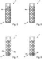
- Fresh water is applied with a relatively small dosage of cleaning agent or with a relatively low surfactant content, which means that it has a lower surface tension than the fresh water, but still a relatively high surface tension, and can then be used for a time of about 3 seconds when the carrier 11 is tilted drain, so a relatively small wet area 28b remains.
- This extends upwards from the lower end area 14 and is somewhat narrower there due to the respective arrangement of the hydrophilic areas 18.
- the liquid therefore naturally begins to flow from top to bottom and to drain off at the bottom in accordance with the effect of the force. It would be similar with airflow or rotation of the carrier as previously described.
- fresh water is applied with a medium dosage of cleaning agent or with a medium surfactant content, which means that it has a mean surface tension that is lower than that of 4 .
- a medium dosage of cleaning agent or with a medium surfactant content which means that it has a mean surface tension that is lower than that of 4 .
- some liquid has drained from the carrier 11, so that a relatively large moist area 28c remains in the measuring area 15. This extends from the lower end area 14 almost to the top and is also something there again narrower.
- the capacitive coupling between the electrodes 20a and 20b compared to 3 significantly increased, which in turn was recorded by capacitive measurement. If the measurement duration were increased from 3 seconds to 5 seconds or even 10 seconds, for example, then a little more liquid would run off, but then the distinguishability would be reduced 3 difficult, since there would possibly be hardly any liquid left.
- the 9 shows an embodiment of a carrier 111 with a significantly higher number of hydrophobic areas 117 and hydrophilic areas 118 in a measurement area 115. They are again arranged in a pattern as before, but twice the number next to each other and one below the other. Thus four times as many areas 117 and 118 are provided.
- connection contacts 125a and 125b are provided on the carrier surface 113 of the carrier substrate 112, to which electrodes, not shown, are attached as in FIG 2 are led. Due to the smaller training of the respective areas 117 and 118 may be a better differentiation of the different surfactant contents, because the amount of liquid remaining in each case may be different.
- the structure of such a device 31 is shown as described above.
- the carrier 11 is held on a short tubular holder 33 which is open at the front towards an interior space 34 and which is closed at the rear. It runs at an angle ⁇ to the dashed central longitudinal axis of the holder 33, which corresponds to the horizontal, which is approximately 55° here.
- This angle ⁇ determines the strength or effect of gravity on the liquid that is on the surface of the carrier 11, i.e. in the measuring area 15.
- a dishwasher 40 In the 12 the structure of a dishwasher 40 according to the invention is shown as a water-bearing household appliance which has a washing chamber 41 as a treatment chamber in which dishes are cleaned. Water is sucked off by a pump 43 from a sump 42 below and pumped through a line 44 into a spray arm 45 . From there, the water is sprayed onto the dishes as rinsing water 47 in corresponding small jets into the rinsing chamber 41 . The water then also splashes onto the device 31 on the right in the side wall with the carrier 11 or onto its measuring area 15. A round hole can be made very easily in the side wall for the round holder 33, in which it is then sealed and attached.
- the carrier 11 is electrically contacted with its connecting contacts 25 and a connecting line 26 and connected to a controller 48 of the dishwasher 40 .
- the controller 48 can then use the aforementioned method to determine how much cleaning agent or tenside is contained in the rinsing water 47 . In this way, a better and possibly more economical dosing can take place, in any case the dosing can be precisely adjusted. So it can be stopped or increased as needed.
- a temperature of the liquid can also be detected or its temperature can be taken into account. This can be done passively using a corresponding temperature sensor, which is either attached to the support 11 or somewhere on the dishwasher or its water supply, for example on the pump 43 or a heater for the water.
- a corresponding temperature sensor which is either attached to the support 11 or somewhere on the dishwasher or its water supply, for example on the pump 43 or a heater for the water.
- the corresponding relationship between temperature and flow behavior has been explained before. It can be calculated out, so to speak, or by heating the carrier 11 appropriately, it can be as constant as possible Temperature for the measurement processes are reached. In this way, an influence of the temperature or a falsification of the measurement process can be reduced as far as possible or avoided entirely.
- the surface tension in the rinsing water 47 can then be determined in the controller 48 by calculation or by comparison with stored values, and then from this its surfactant content.
- the controller 48 can use this to better adjust the dosage of cleaning agent into the rinsing water 47 .
Description
Die Erfindung betrifft ein Verfahren zur Untersuchung einer Flüssigkeit in einem wasserführenden Haushaltsgerät, wobei dabei eine Oberflächenspannung bzw. ein Tensidgehalt einer Flüssigkeit, die in dem Haushaltsgerät benutzt wird oder benutzt werden soll, erfasst werden soll. Des Weiteren betrifft die Erfindung ein entsprechend ausgebildetes wasserführendes Haushaltsgerät, insbesondere eine Spülmaschine oder eine Waschmaschine.The invention relates to a method for examining a liquid in a water-bearing household appliance, whereby a surface tension or a surfactant content of a liquid that is used or is to be used in the household appliance is to be recorded. Furthermore, the invention relates to a correspondingly designed water-carrying household appliance, in particular a dishwasher or a washing machine.
Für eine Vielzahl von Reinigungsvorgängen in einer Spülmaschine oder Waschmaschine ist es von Vorteil, wenn die Oberflächenspannung des Wassers erfasst werden kann, insbesondere um eine Konzentration an darin enthaltenen Tensiden von Reinigern zu bestimmen. So können ein Verschmutzungsgrad sowie eine Dosierung von Reiniger bestimmt werden.For a large number of cleaning processes in a dishwasher or washing machine, it is advantageous if the surface tension of the water can be recorded, in particular in order to determine a concentration of detergent surfactants contained therein. In this way, the degree of soiling and the dosage of cleaning agent can be determined.
Aus der
Aus der
Aus der
Aus der
Der Erfindung liegt die Aufgabe zugrunde, ein eingangs genanntes Verfahren sowie ein eingangs genanntes wasserführendes Haushaltsgerät zu schaffen, mit denen Probleme des Standes der Technik gelöst werden können und es insbesondere möglich ist, eine Oberflächenspannung einer Flüssigkeit in einem solchen Gerät einfach, zuverlässig und schnell zu messen.The invention is based on the object of creating a method as mentioned at the outset and a water-conducting household appliance as mentioned at the outset, with which problems of the prior art can be solved and in particular it is possible to increase the surface tension of a liquid in such a device simply, reliably and quickly measure.
Gelöst wird diese Aufgabe durch ein Verfahren mit den Merkmalen des Anspruchs 1 sowie durch ein wasserführendes Haushaltsgerät mit den Merkmalen des Anspruchs 15. Vorteilhafte sowie bevorzugte Ausgestaltungen der Erfindung sind Gegenstand der weiteren Ansprüche und werden im Folgenden näher erläutert. Dabei werden manche der Merkmale nur für das Verfahren oder nur für das Haushaltsgerät beschrieben. Sie sollen jedoch unabhängig davon sowohl für das Verfahren als auch für das Haushaltsgerät selbständig und unabhängig voneinander gelten können. Der Wortlaut der Ansprüche wird durch ausdrückliche Bezugnahme zum Inhalt der Beschreibung gemacht.This object is achieved by a method having the features of claim 1 and by a water-bearing household appliance having the features of
Es ist vorgesehen, dass das Verfahren zum Erfassen einer Oberflächenspannung einer Flüssigkeit bei einer Untersuchung die im Folgenden genannten Schritte aufweist. Zuerst wird ein flacher und flächiger Träger bereitgestellt bzw. ist in einer entsprechenden Vorrichtung eines Haushaltsgeräts oder in dem Haushaltsgerät vorgesehen. Der Träger weist eine flache und flächige Trägeroberfläche auf. Vorteilhaft ist die Trägeroberfläche plan, also eben, sie kann aber auch leicht gewölbt sein bzw. leicht gebogen sein. Auf der Trägeroberfläche sind abwechselnd Hydrophob-Bereiche und Hydrophil-Bereiche vorgesehen. Diese definieren sich dadurch, dass die Hydrophil-Bereiche hydrophil sind und Wasser eher anziehen bzw. Wasser sich leicht darauf ablagern kann. Die Hydrophob-Bereiche sind das Gegenteil davon, sie sind hydrophob und stoßen Wasser eher ab. In Ausgestaltung der Erfindung ist vorteilhaft die Adhäsionskraft der Hydrophob-Bereiche und der Hydrophil-Bereiche unterschiedlich, wobei besonders vorteilhaft eine Differenz der jeweiligen Adhäsionskraft mindestens 40 mN/m beträgt, insbesondere mindestens 100 mN/m. Dabei können bevorzugt die Hydrophob-Bereiche und die Hydrophil-Bereiche direkt aneinanderstoßen, also ohne dazwischenliegende Bereiche, Übergänge odgl..It is intended that the method for detecting a surface tension of a liquid in an examination has the following steps. First, a flat and planar carrier is provided or is provided in a corresponding device of a household appliance or in the household appliance. The carrier has a flat and planar carrier surface. Advantageously, the support surface is flat, ie flat, but it can also be slightly arched or slightly curved. Alternating hydrophobic areas and hydrophilic areas are provided on the carrier surface. These are defined by the fact that the hydrophilic areas are hydrophilic and tend to attract water or water can easily deposit on it. The hydrophobic areas are the opposite of this, they are hydrophobic and tend to repel water. In an embodiment of the invention, the adhesive force of the hydrophobic areas and the hydrophilic areas is advantageously different, a difference in the respective adhesive force being particularly advantageously at least 40 mN/m, in particular at least 100 mN/m. The hydrophobic areas and the hydrophilic areas can preferably abut one another directly, i.e. without intermediate areas, transitions or the like.
In einem nächsten Schritt wird die zu untersuchende Flüssigkeit auf die Trägeroberfläche aufgebracht. Dies kann in einem bewussten Schritt erfolgen, beispielsweise entweder durch gezieltes Pumpen oder indem die Trägeroberfläche während eines Betriebs des Haushaltsgeräts mit Flüssigkeit automatisch benetzt bzw. bespritzt wird. Anschließend wird die Flüssigkeit, die auf der Trägeroberfläche ist, einer Krafteinwirkung ausgesetzt bzw. eine Kraft kann aufgebracht oder sozusagen gestartet werden. Diese Krafteinwirkung ist derart bzw. dazu ausgebildet, dass sie versucht, die Flüssigkeit von der Trägeroberfläche zumindest teilweise zu entfernen bzw. dass sie allgemein versucht, die Flüssigkeit von der Trägeroberfläche wegzubewegen. Dabei muss bzw. sollte nicht zwingend die gesamte Flüssigkeit entfernt werden. Vorteilhaft wird mindestens ein Teil der Flüssigkeit auf der Trägeroberfläche belassen, indem die Krafteinwirkung entsprechend ausgestaltet ist hinsichtlich Richtung, Stärke bzw. Intensität und/oder Dauer ihrer Einwirkung. Danach wird erfasst, ob sich noch Flüssigkeit auf der Trägeroberfläche befindet bzw. welche Menge an Flüssigkeit noch auf der Trägeroberfläche verblieben ist, ggf. welche Fläche noch von Flüssigkeit bedeckt ist. Dies wird dann als Maß für die Oberflächenspannung bzw. den Tensidgehalt der untersuchten Flüssigkeit herangezogen. Je weniger Flüssigkeit auf der Trägeroberfläche verbleibt, als desto größer wird die Oberflächenspannung der Flüssigkeit angenommen bzw. bestimmt. Je mehr Flüssigkeit auf der Trägeroberfläche verbleibt, als desto geringer wird die Oberflächenspannung der Flüssigkeit angenommen bzw. bestimmt.In a next step, the liquid to be examined is applied to the carrier surface. This can be done in a deliberate step, for example either through targeted pumping or by automatically wetting or spraying the carrier surface with liquid while the household appliance is in operation. The liquid that is on the support surface is then subjected to the action of a force or a force can be applied or, so to speak, started. This force is such that it tries to at least partially remove the liquid from the carrier surface or that it generally tries to move the liquid away from the carrier surface. Included it is not necessary or should not be necessary to remove all of the liquid. Advantageously, at least part of the liquid is left on the support surface, in that the force is applied appropriately in terms of the direction, strength or intensity and/or duration of its effect. Then it is detected whether there is still liquid on the carrier surface or what amount of liquid is still left on the carrier surface, if necessary which area is still covered by liquid. This is then used as a measure of the surface tension or the tenside content of the liquid being examined. The less liquid remains on the carrier surface, the greater the surface tension of the liquid is assumed or determined to be. The more liquid that remains on the carrier surface, the lower the surface tension of the liquid is assumed or determined to be.
Dies liegt daran, dass erfindungsgemäß genutzt wird, dass sich durch die Differenz der Adhäsionskraft für Wasser auf der Trägeroberfläche durch die Hydrophob-Bereiche und die Hydrophil-Bereiche das Wasser bei geringer Oberflächenspannung der Flüssigkeit gut verteilt und möglicherweise noch auf den Hydrophob-Bereichen verbleibt. Somit kann zumindest hier trotz der Krafteinwirkung ein sehr dünner Flüssigkeitsfilm verbleiben, insgesamt also relativ viel Flüssigkeit verbleiben. Ist die Oberflächenspannung der Flüssigkeit dagegen relativ groß oder sehr groß, so zieht sich auch die Flüssigkeit von den Hydrophob-Bereichen zurück auf die Hydrophil-Bereiche und kann dann die Hydrophob-Bereiche nicht mehr überbrücken. Durch die abwechselnde Anordnung mehrerer Hydrophob-Bereiche und Hydrophil-Bereiche kann erreicht werden, dass sich insgesamt bewirken lässt, dass eine Flüssigkeit mit großer Oberflächenspannung, beispielsweise Frischwasser, nur in geringer Menge oder gar nicht auf der Trägeroberfläche verbleibt. Ist die Oberflächenspannung dagegen gering, beispielsweise weil im Betrieb des Haushaltsgeräts viel Reiniger bzw. Tensid zugegeben worden ist, so kann ein Großteil oder die gesamte Trägeroberfläche mit der Flüssigkeit benetzt bleiben. Dies ist dann eben ein Anzeichen bzw. ein Maß für die vorhandene geringe Oberflächenspannung der Flüssigkeit. Anhand der verbliebenen Menge an Flüssigkeit auf der Trägeroberfläche kann dann, wie vorbeschrieben, die Oberflächenspannung der Flüssigkeit zumindest relativ erfasst werden. Durch Vergleich mit abgespeicherten Werten für die verbliebene Menge an Flüssigkeit kann dann qualitativ oder auch quantitativ die Oberflächenspannung der Flüssigkeit erfasst und bestimmt werden.This is because, according to the invention, use is made of the fact that due to the difference in the adhesive force for water on the carrier surface through the hydrophobic areas and the hydrophilic areas, the water is well distributed when the surface tension of the liquid is low and possibly still remains on the hydrophobic areas. Thus, a very thin film of liquid can remain at least here despite the action of the force, that is to say a relatively large amount of liquid can remain overall. On the other hand, if the surface tension of the liquid is relatively high or very high, the liquid also pulls back from the hydrophobic areas to the hydrophilic areas and can then no longer bridge the hydrophobic areas. By arranging several hydrophobic areas and hydrophilic areas alternately, it can be achieved that a liquid with high surface tension, for example fresh water, remains only in small amounts or not at all on the carrier surface. On the other hand, if the surface tension is low, for example because a large amount of cleaning agent or surfactant has been added during operation of the household appliance, a large part or the entire carrier surface can remain wetted with the liquid. This is then just an indication or a measure of the existing low surface tension of the liquid. Based on the amount of liquid remaining on the carrier surface, the surface tension of the liquid can then be determined, at least relatively, as described above. The surface tension of the liquid can then be recorded and determined qualitatively or quantitatively by comparison with stored values for the remaining amount of liquid.
In vorteilhafter Ausgestaltung der Erfindung können die Hydrophob-Bereiche und die Hydrophil-Bereiche ein regelmäßiges Muster in einer Richtung bzw. entlang einer Richtung auf der Trägeroberfläche bilden. So können also in dieser Richtung mehrere Hydrophob-Bereiche und Hydrophil-Bereiche abwechselnd angeordnet sein, beispielsweise dreimal ein Wechsel zwischen einem Hydrophob-Bereich und einem Hydrophil-Bereich bzw. anders herum vorgesehen sein. Es können also beispielsweise vorteilhaft in dieser Richtung zwei Hydrophob-Bereiche und zwei Hydrophil-Bereiche vorgesehen sein, möglicherweise auch jeweils drei oder vier.In an advantageous embodiment of the invention, the hydrophobic areas and the hydrophilic areas can form a regular pattern in one direction or along one direction on the carrier surface. Thus, in this direction, a plurality of hydrophobic areas and hydrophilic areas can be arranged alternately, for example alternating between a hydrophobic area and a hydrophilic area or vice versa can be provided three times be. Thus, for example, two hydrophobic areas and two hydrophilic areas can advantageously be provided in this direction, possibly also three or four each.
Um eine größere wirksame Trägeroberfläche zu schaffen, auf der Flüssigkeit verbleiben kann, kann vorgesehen sein, dass auch in einer zweiten Richtung, die rechtwinklig zur vorgenannten Richtung auf der Trägeroberfläche verläuft, Hydrophob-Bereiche und Hydrophil-Bereiche abwechselnd vorgesehen sind bzw. ein regelmäßiges Muster bilden. Auch hier kann mindestens zweimal oder dreimal ein Wechsel zwischen einem Hydrophob-Bereich und einem Hydrophil-Bereich vorgesehen sein, vorteilhaft noch mehr. Besonders vorteilhaft können in einer Richtung erheblich mehr Hydrophob-Bereiche und Hydrophil-Bereiche abwechselnd vorgesehen sein als in einer anderen Richtung rechtwinklig dazu. Hier kann der Träger bevorzugt länglich, besonders bevorzugt rechteckig, ausgebildet sein.In order to create a larger effective carrier surface on which liquid can remain, it can be provided that hydrophobic areas and hydrophilic areas are also provided alternately or a regular pattern in a second direction, which runs at right angles to the aforementioned direction on the carrier surface form. Here, too, a change between a hydrophobic area and a hydrophilic area can be provided at least twice or three times, advantageously even more. Particularly advantageously, considerably more hydrophobic areas and hydrophilic areas can be provided alternately in one direction than in another direction at right angles thereto. Here, the carrier can preferably be elongate, particularly preferably rectangular.
Von Vorteil ist es, wenn alle Hydrophob-Bereiche jeweils gleich groß ausgebildet sind. Zusätzlich oder alternativ können auch alle Hydrophil-Bereiche jeweils gleich groß ausgebildet sein. So können gleichmäßige Verhältnisse geschaffen werden. Besonders vorteilhaft sind alle Hydrophob-Bereiche und/oder alle Hydrophil-Bereiche jeweils identisch ausgebildet, also mit gleicher Fläche und gleicher Form, insbesondere allesamt identisch.It is advantageous if all of the hydrophobic areas are of the same size. In addition or as an alternative, all hydrophilic areas can also be of the same size. In this way, even conditions can be created. It is particularly advantageous for all hydrophobic areas and/or all hydrophilic areas to be configured identically, ie with the same area and the same shape, in particular all of them identical.
In Ausgestaltung der Erfindung können die Hydrophob-Bereiche und die Hydrophil-Bereiche jeweils rechteckig ausgebildet sein. So kann es ermöglicht werden, dass die Bereiche jeweils in den Ecken direkt aneinanderstoßen, also zwischen benachbarten Bereichen mit unterschiedlicher Adhäsionskraft ihrer Oberfläche keine Zwischenbereiche vorgesehen sind. So können die Bereiche eine Trägeroberfläche vollständig bedecken. Eine besonders vorteilhafte Ausgestaltung sieht vor, dass die Bereiche jeweils quadratisch sind.In an embodiment of the invention, the hydrophobic areas and the hydrophilic areas can each be rectangular. It can thus be made possible for the areas to abut directly in the corners, that is to say no intermediate areas are provided between adjacent areas with different adhesive forces on their surface. In this way, the areas can completely cover a carrier surface. A particularly advantageous embodiment provides that the areas are each square.
Von der Größe her bietet es sich an, die Bereiche mit einer Größe im Millimeter-Bereich auszugestalten. So können eine Länge und/oder eine Breite der jeweiligen Bereiche zwischen 1 mm und 5 mm liegen, vorteilhaft zwischen 2 mm und 4 mm. Dann können auf einer Trägeroberfläche mit den Abmessungen zwischen 10 mm und 15 mm Breite sowie zwischen 20 mm und 40 mm Länge jeweils zwei bis drei Bereiche jeder Art in der Richtung der Breite und fünf bis zehn Bereiche jeder Art in der Länge der Trägeroberfläche vorgesehen sein bei der vorgenannten möglichen Größe für die Bereiche. Bei einer derartigen Große lässt sich ein erfindungsgemäßer Träger noch gut herstellen mit ausreichender erforderlicher Genauigkeit ohne allzu großen Aufwand. Des Weiteren lässt er sich auch gut in ein wasserführendes Haushaltsgerät integrieren, um dort praxistauglich die Erfassung durchführen zu können.In terms of size, it makes sense to design the areas with a size in the millimeter range. A length and/or a width of the respective areas can be between 1 mm and 5 mm, advantageously between 2 mm and 4 mm. Then, on a support surface with dimensions between 10 mm and 15 mm in width and between 20 mm and 40 mm in length, two to three areas of each type can be provided in the width direction and five to ten areas of each type in the length of the support surface the aforementioned possible size for the areas. With such a size, a carrier according to the invention can still be produced well with the required accuracy and without too much effort. Furthermore, it can also be easily integrated into a water-bearing household appliance in order to be able to carry out the recording there in a practical way.
Für die Krafteinwirkung kann vorteilhaft vorgesehen sein, dass sie eine bestimmte Richtung aufweist bzw. eine gerichtete Krafteinwirkung ist. Es kann vorgesehen sein, dass entlang der genannten Richtung der Krafteinwirkung mehr Hydrophob-Bereiche und Hydrophil-Bereiche vorgesehen sind als in einer Richtung rechtwinklig dazu. So kann durch die gerichtete Krafteinwirkung die Flüssigkeit entlang einer möglichst großen Strecke über die abwechselnden Bereiche mit unterschiedlicher Adhäsionskraft bewegt werden, was eine besonders gute und differenzierte Aussage über die Oberflächenspannung der Flüssigkeit ermöglicht. Deswegen ist die Trägeroberfläche eben in Richtung entlang der Kraftwirkung vorteilhaft länger als in der anderen Richtung rechtwinklig dazu, vorzugsweise zweimal so lang bis zu zehnmal so lang.It can advantageously be provided that the force is applied in a specific direction or is a directed force. Provision can be made for more hydrophobic areas and hydrophilic areas to be provided along said direction of force action than in a direction at right angles thereto. In this way, the liquid can be moved along the greatest possible distance over the alternating areas with different adhesion forces through the directed action of force, which enables a particularly good and differentiated statement to be made about the surface tension of the liquid. Therefore, the carrier surface is advantageously longer in the direction along the action of the force than in the other direction perpendicular thereto, preferably twice as long up to ten times as long.
In vorteilhafter Ausgestaltung der Erfindung können die Hydrophob-Bereiche und/oder die Hydrophil-Bereiche entlang der Richtung der Krafteinwirkung bzw. in der Richtung, in der sich die Flüssigkeit durch die Krafteinwirkung bewegt bei ihrem Entfernen, dieselbe Ausdehnung aufweisen wie in einer Richtung rechtwinklig dazu. Wie zuvor ausgeführt worden ist, sind vorteilhaft die Bereiche jeweils quadratisch ausgebildet, dann ist diese Bedingung leicht erfüllbar.In an advantageous embodiment of the invention, the hydrophobic areas and/or the hydrophilic areas can have the same extent along the direction of the force effect or in the direction in which the liquid moves due to the force effect when it is removed as in a direction perpendicular thereto . As has been explained above, the areas are each advantageously of square design, then this condition can be easily met.
In einer ersten Ausgestaltung der Erfindung kann die Krafteinwirkung ein Luftstrom sein, beispielsweise durch ein Gebläse hervorgerufen werden. Dies kann ein separates Gebläse eigens für diese Krafteinwirkung sein, alternativ kann ein ohnehin in dem Haushaltsgerät hergestellter bzw. bestehender Luftstrom oder ein entsprechendes Gebläse hierfür genutzt werden. Ein solcher Luftstrom kann sehr gleichmäßig auf die auf der Trägeroberfläche befindliche Flüssigkeit einwirken, beispielsweise weil er schräg darauf gerichtet ist und somit eigentlich die gleiche Auswirkung auf sämtliche auf der Trägeroberfläche befindliche Flüssigkeit hat.In a first embodiment of the invention, the force can be an air flow, for example caused by a fan. This can be a separate blower specifically for this action of force; alternatively, an air flow that is already produced or existing in the household appliance or a corresponding blower can be used for this purpose. Such an air flow can act very uniformly on the liquid located on the carrier surface, for example because it is directed at an angle and thus actually has the same effect on all liquid located on the carrier surface.
In alternativer Ausgestaltung der Erfindung kann die Krafteinwirkung durch die Schwerkraft gebildet werden bzw. kann die Schwerkraft für die Krafteinwirkung genutzt werden. Diese Schwerkraft ist ja ohnehin vorhanden. Hierfür kann der Träger mit seiner Trägeroberfläche schräggestellt werden in einem Winkel zwischen 10° und 80° zur Horizontalen. Vorteilhaft bleibt der Träger stets in einem bestimmten Winkel angeordnet, auch wenn er grundsätzlich verstellbar sein könnte, um die Krafteinwirkung verändern zu können bzw. variabel zu machen. Ein vorteilhafter Winkel für die Krafteinwirkung auf den Träger bzw. auf Flüssigkeit, die sich auf der Trägeroberfläche befindet, liegt besonders vorteilhaft zwischen 30° und 60°. Der Vorteil der Verwendung der Schwerkraft liegt erkennbar darin, dass keine separate Krafterzeugung notwendig ist. Des Weiteren ist die Schwerkraft sehr beständig und gleichzeitig auch weltweit gleich bzw. ausreichend gleich. Alternativ kann der Träger gedreht werden, so dass die von der Drehgeschwindigkeit abhängige Fliehkraft diejenige Kraft ist, die die Flüssigkeit von der Trägeroberfläche zu entfernen versucht. Sie kann auch durch die Drehgeschwindigkeit variiert werden.In an alternative embodiment of the invention, the force can be generated by gravity or gravity can be used for the force. This gravity is there anyway. For this purpose, the carrier can be tilted with its carrier surface at an angle of between 10° and 80° to the horizontal. Advantageously, the carrier is always arranged at a specific angle, even if it could in principle be adjustable in order to be able to change the force effect or make it variable. An advantageous angle for the force to act on the carrier or on the liquid that is on the carrier surface is particularly advantageously between 30° and 60°. The advantage of using gravity is recognizable in the fact that no separate force generation is necessary. Furthermore, gravity is very constant and at the same time the same or sufficiently the same worldwide. Alternatively, the carrier can be rotated so that the centrifugal force, which is dependent on the rate of rotation, is the force that tries to remove the liquid from the carrier surface. It can also be varied by the rotation speed.
Bezüglich des vorgenannten zeitlichen Aspekts der Erfassung der verbleibenden Menge an Flüssigkeit auf der Trägeroberfläche wird es als vorteilhaft angesehen, wenn die Erfassung einige Sekunden gewartet wird nach Aufbringen der Flüssigkeit auf die Trägeroberfläche bzw. nach Beginn der Krafteinwirkung. Vorteilhaft sind dies 2 sec bis 20 sec, besonders vorteilhaft 5 sec bis 10 sec. Somit kann ohnehin überschüssige Flüssigkeit von der Trägeroberfläche abfließen, die sich unabhängig von der jeweils vorhandenen Oberflächenspannung der Flüssigkeit nicht halten könnte. Des Weiteren kann für diese Zeit die Krafteinwirkung sozusagen wirken bzw. ihre Wirkung entfalten. Dadurch ist es möglich, dass sozusagen immer gleiche Verhältnisse aufgrund der Krafteinwirkung nach dieser Zeit von wenigen Sekunden vorherrschen, so dass die Messungen vergleichbar sind und einen guten Rückschluss auf die tatsächliche Oberflächenspannung der Flüssigkeit ermöglichen.With regard to the aforementioned temporal aspect of detecting the amount of liquid remaining on the carrier surface, it is considered advantageous if the detection is delayed a few seconds after the liquid has been applied to the carrier surface or after the force has started to act. This is advantageous for 2 seconds to 20 seconds, particularly advantageous for 5 seconds to 10 seconds. In this way, excess liquid can flow off the carrier surface anyway, which liquid could not hold independently of the existing surface tension of the liquid. Furthermore, the action of force can act, so to speak, or unfold its effect for this time. As a result, it is possible for the same conditions to prevail, so to speak, due to the effect of force after this time of a few seconds, so that the measurements are comparable and enable a good conclusion to be drawn about the actual surface tension of the liquid.
Zur Erfassung der Menge der auf der Trägeroberfläche gegebenenfalls verbleibenden Flüssigkeit gibt es mehrere Möglichkeiten. Gemäß einer ersten Möglichkeit wird die Menge kapazitiv erfasst. Dazu können vorteilhaft am Träger angebrachte elektrisch leitfähige Elektroden vorgesehen sein, wobei deren Kapazität untereinander bzw. eine kapazitive Kopplung zwischen den Elektroden, vorzugsweise zwei Elektroden, gemessen wird. Dabei können die Elektroden so angeordnet sein, dass eben die Kapazität zwischen ihnen bzw. die kapazitive Kopplung zwischen ihnen von der Menge an Flüssigkeit auf der Trägeroberfläche abhängt bzw. in einem bestimmten Verhältnis dazu steht. Dazu sollten die beiden Elektroden einen gewissen Abstand voneinander aufweisen, der vorteilhaft nicht zu groß ist, beispielsweise maximal 2 mm. In vorteilhafter Ausgestaltung der Erfindung können die Elektroden fingerartig bzw. schmal und länglich ausgebildet sein. Dabei können sie sozusagen ineinander verschränkt sein, beispielsweise wie zwei ineinander ragende Kämme. So wird zum einen besonders viel Fläche erreicht, an denen die beiden Elektroden einen geringen Abstand zueinander aufweisen, da hier die kapazitive Kopplung zwischen ihnen gegeben ist, welche durch die Menge an vorhandener Flüssigkeit beeinflussbar ist. Zum anderen kann dieser Bereich der nahe beieinanderliegenden Anordnung vorteilhaft möglichst weitgehend über die Trägeroberfläche verteilt sein, wo eben Flüssigkeit vorhanden sein kann, so dass sich die gegebenenfalls vorhandene Menge an Flüssigkeit besonders gut auswirken kann. Dies wiederum kann eben an den beiden Elektroden durch Kapazitätsmessung erfasst werden. Vorteilhaft verlaufen die Elektroden dabei entlang von gegenüberliegenden längeren Längsseiten der Trägeroberfläche, wobei fingerartige längliche schmale Abschnitte davon rechtwinklig abstehen bzw. zur gegenüberliegenden Elektrode hin verlaufen.There are several ways of detecting the amount of liquid that may remain on the carrier surface. According to a first option, the quantity is detected capacitively. For this purpose, electrically conductive electrodes attached to the carrier can advantageously be provided, with their capacitance among one another or a capacitive coupling between the electrodes, preferably two electrodes, being measured. The electrodes can be arranged in such a way that the capacitance between them or the capacitive coupling between them depends on the amount of liquid on the carrier surface or is in a specific ratio thereto. To this end, the two electrodes should be at a certain distance from one another, which is advantageously not too great, for example a maximum of 2 mm. In an advantageous embodiment of the invention, the electrodes can be finger-like or narrow and elongated. They can, so to speak, be intertwined, for example like two combs protruding into one another. On the one hand, a particularly large area is achieved on which the two electrodes are at a small distance from one another, since the capacitive coupling between them is given here, which can be influenced by the amount of liquid present. On the other hand, this area of the arrangement lying close to one another can advantageously be distributed as widely as possible over the support surface where liquid can be present, so that the amount of liquid that may be present can have a particularly good effect. This in turn can be detected at the two electrodes by measuring the capacitance. Advantageously, the electrodes run along opposite, longer longitudinal sides of the carrier surface, with finger-like, elongated, narrow sections protruding from them at right angles or running towards the opposite electrode.
Gemäß einer zweiten Möglichkeit kann die Menge der ggf. auf der Trägeroberfläche verbleibenden Flüssigkeit optisch erfasst werden. Hierfür kann eine Transmissions-Messung, eine Messung der Lichtbrechung oder eine Messung der Reflexion verwendet werden. Dabei kann ausgenutzt werden, dass sich die jeweiligen Eigenschaften der Transmission, der Lichtbrechung oder vor allem der Reflexion der Trägeroberfläche ändern, abhängig davon ob und ggf. wie viel Flüssigkeit darauf vorhanden ist. So kann beispielsweise die Trägeroberfläche an sich matt sein bzw. eine geringe Reflexion aufweisen. Befindet sich Flüssigkeit darauf, so kann diese bekanntermaßen deutlich besser reflektierend ausgebildet sein, was eben bei einer Messung der Reflexion, vorteilhaft mit einer breit streuenden Lichtquelle und einem Lichtempfänger, festgestellt werden kann.According to a second possibility, the amount of liquid possibly remaining on the carrier surface can be detected optically. A transmission measurement, a measurement of the refraction of light or a measurement of the reflection can be used for this. Thereby can be exploited that the respective properties of transmission, light refraction or especially the reflection of the carrier surface change, depending on whether and possibly how much liquid is present on it. For example, the carrier surface itself can be matt or have low reflection. If there is liquid on it, it can, as is known, be designed to be significantly more reflective, which can be determined by measuring the reflection, advantageously with a widely scattering light source and a light receiver.
Eine weitere dritte Möglichkeit zur Erfassung der gegebenenfalls auf der Trägeroberfläche verbleibenden Menge an Flüssigkeit kann eine Gewichtsmessung bzw. eine Messung der Gewichtskraft sein, die vom Träger ausgeübt wird. Hierfür kann der Träger an einem entsprechenden Gewichtssensor angeordnet sein, vorzugsweise daran aufgehängt oder darauf aufliegend.Another third option for detecting the amount of liquid that may remain on the carrier surface can be a weight measurement or a measurement of the weight exerted by the carrier. For this purpose, the carrier can be arranged on a corresponding weight sensor, preferably suspended from it or lying on it.
In vorteilhafter Ausgestaltung der Erfindung ist die Trägeroberfläche derart nahe an einer Wasserführung und/oder Behandlungskammer des wasserführenden Haushaltsgeräts angeordnet, dass das Aufbringen von Flüssigkeit auf die Trägeroberfläche während des regulären Betriebs des Haushaltsgeräts sehr einfach möglich ist, vorteilhaft automatisch erfolgt. So kann der Träger bzw. die Trägeroberfläche beispielsweise in einem Behandlungsraum des Haushaltsgeräts angeordnet sein oder vorteilhaft seitlich an einer Wandung davon. Möglicherweise kann hier eine Klappe oder sonstige Ventileinrichtung zu dem Behandlungsraum oder zu der Wasserführung vorgesehen sein, durch deren jeweilige Betätigung tatsächlich eine genau gezielte Aufbringung von Flüssigkeit auf den Träger möglich ist. Falls dieser Aufwand eingespart werden soll, ist es auch möglich, wenn der Träger einfach offen in einer Seitenwand der Behandlungskammer angeordnet ist und dann, beispielsweise in einer Spülmaschine, regelmäßig mit Flüssigkeit bzw. Wasser bespritzt wird. Dies kann beispielsweise durch jeweils umlaufende Spülarme mit zeitlichem Abstand von wenigen Sekunden erfolgen.In an advantageous embodiment of the invention, the carrier surface is arranged so close to a water supply and/or treatment chamber of the water-bearing household appliance that liquid can be applied to the carrier surface very easily during regular operation of the household appliance, advantageously automatically. For example, the carrier or the carrier surface can be arranged in a treatment room of the household appliance or advantageously on the side on a wall thereof. A flap or other valve device for the treatment room or for the water supply can possibly be provided here, through the actuation of which a precisely targeted application of liquid to the wearer is actually possible. If this effort is to be saved, it is also possible if the carrier is simply arranged openly in a side wall of the treatment chamber and is then regularly sprayed with liquid or water, for example in a dishwasher. This can be done, for example, by circulating spray arms at intervals of a few seconds.
Gemäß einer vorteilhaften Weiterbildung der Erfindung kann vorgesehen sein, dass der Träger beheizbar ist bzw. beheizt wird. Hierfür kann an dem Träger eine Heizeinrichtung vorgesehen sein, vorteilhaft an einer von der Trägeroberfläche abgewandten Seite des Trägers, also an einer Trägerunterseite. Eine Heizeinrichtung kann vorteilhaft eine Dickschichtheizung oder eine andere flächig verteilte Heizung sein, beispielsweise mit mäanderförmigem Verlauf für eine möglichst gleichmäßige Beheizung der Trägeroberfläche bzw. des Trägers. Hierbei kann genutzt werden, dass die Temperatur ebenfalls eine Auswirkung auf die Oberflächenspannung der Flüssigkeit aufweist. Es kann also mit Variation der Temperatur der Trägeroberfläche und somit auch der gegebenenfalls darauf befindlichen Flüssigkeit noch genauer deren Oberflächenspannung bzw. Tensidgehalt bestimmt werden. So nimmt üblicherweise die Oberflächenspannung mit zunehmender Temperatur ab. Zwischen Flüssigkeiten mit 20°C und mit 60°C nimmt die Oberflächenspannung in der Regel etwa 20 % ab, was einen gut messbaren Effekt gibt.According to an advantageous development of the invention, it can be provided that the carrier can be heated or is heated. For this purpose, a heating device can be provided on the carrier, advantageously on a side of the carrier facing away from the carrier surface, ie on a carrier underside. A heating device can advantageously be a thick-film heater or another type of heater distributed over a large area, for example with a meandering course for heating the carrier surface or the carrier as uniformly as possible. The fact that the temperature also has an effect on the surface tension of the liquid can be used here. Thus, by varying the temperature of the carrier surface and thus also of the liquid that may be present on it, its surface tension or surfactant content can be determined even more precisely. So usually increases the surface tension with increasing temperature. Between liquids at 20°C and 60°C, the surface tension usually decreases by about 20%, which gives an easily measurable effect.
In weiterer Ausgestaltung der Erfindung kann eine Temperatur des Trägers bzw. der Trägeroberfläche und/oder der Flüssigkeit auf dem Träger bestimmt werden. So kann eben auch die Temperaturabhängigkeit der Oberflächenspannung der Flüssigkeit erfasst werden. Dazu kann vorteilhaft ein Temperatursensor direkt auf dem Träger aufgebracht sein, vorzugsweise auf der Trägeroberfläche, um möglichst gut nicht nur deren Temperatur, sondern auch diejenige der darauf befindlichen Flüssigkeit erfasst werden. Aus der Temperatur der vorhandenen Flüssigkeit sowie deren Menge kann dann die Oberflächenspannung bestimmt werden. Des Weiteren ist es insbesondere mit einer vorgenannten Heizeinrichtung am Träger möglich, dass unabhängig von der Temperatur im Behandlungsraum bzw. der Flüssigkeit an sich stets dieselben Temperaturbedingungen auf der Trägeroberfläche eingestellt werden, damit konstant und möglichst genau gemessen werden kann.In a further embodiment of the invention, a temperature of the carrier or the carrier surface and/or the liquid on the carrier can be determined. In this way, the temperature dependency of the surface tension of the liquid can also be recorded. For this purpose, a temperature sensor can advantageously be applied directly to the carrier, preferably on the carrier surface, in order to detect not only its temperature but also that of the liquid on it as well as possible. The surface tension can then be determined from the temperature of the liquid present and its quantity. Furthermore, it is possible, in particular with an aforementioned heating device on the carrier, to always set the same temperature conditions on the carrier surface, regardless of the temperature in the treatment room or the liquid itself, so that measurements can be constant and as accurate as possible.
in einer vorteilhaften Ausgestaltung der Erfindung unterscheiden sich die Hydrophob-Bereiche und die Hydrophil-Bereiche durch das Material ihrer Oberfläche. So kann mindestens einer der Bereiche eine Beschichtung aufweisen, vorteilhaft der Hydrophob-Bereich. Eine solche Beschichtung kann aus der Gruppe DLC-Beschichtung, Parylen, PTFE oder Nano-Beschichtung mit Lotoseffekt ausgewählt werden. Diese Beschichtung kann dann im Muster der Hydrophob-Bereiche aufgebracht werden. Kunststoff-Beschichtungen haben sich als relativ einfach herstellbar herausgestellt, insbesondere als Kunststoffbedampfung. Alternativ kann ein Siebdruckverfahren verwendet werden, oder aus einer vollflächigen Beschichtung kann das Muster herausgearbeitet werden.In an advantageous embodiment of the invention, the hydrophobic areas and the hydrophilic areas differ in the material of their surface. At least one of the areas can have a coating, advantageously the hydrophobic area. Such a coating can be selected from the group of DLC coating, parylene, PTFE or nano-coating with lotus effect. This coating can then be applied in the pattern of the hydrophobic areas. Plastic coatings have proven to be relatively easy to produce, in particular as plastic vapor deposition. Alternatively, a screen printing process can be used, or the pattern can be worked out of a full-surface coating.
In alternativer Ausgestaltung der Erfindung unterscheiden sich die Hydrophob-Bereiche und die Hydrophil-Bereiche hinsichtlich einer Oberflächenstruktur voneinander. Dazu können die Hydrophil-Bereiche eine größere Oberflächenrauheit aufweisen als die Hydrophob-Bereiche, so dass Flüssigkeit darauf eben leichter bzw. besser verbleiben kann. Eine solche unterschiedliche Oberflächenrauheit kann durch eine partielle Oberflächenstrukturierung erreicht werden. Möglichkeiten hierfür sind Siebdruck, partielles bzw. maskiertes Sandstrahlen oder sonstiges Strahlen, partielles Polieren, maskiertes Ätzen oder Lasern, beispielsweise als sogenanntes Laser-Scribing. Selbst in den vorgenannten relativ kleinen Abmessungen können somit die gewünschten unterschiedlichen Oberflächenrauheiten hergestellt werden. Alternativ kann auch die Oberflächenrauheit verringert werden durch jeweiliges feines Polieren.In an alternative embodiment of the invention, the hydrophobic areas and the hydrophilic areas differ from one another with regard to a surface structure. In addition, the hydrophilic areas can have a greater surface roughness than the hydrophobic areas, so that liquid can remain on them more easily or better. Such a different surface roughness can be achieved by partial surface structuring. Possibilities for this are screen printing, partial or masked sandblasting or other types of blasting, partial polishing, masked etching or lasers, for example as so-called laser scribing. The desired different surface roughnesses can thus be produced even in the aforementioned relatively small dimensions. Alternatively, the surface roughness can also be reduced by respective fine polishing.
Ausführungsbeispiele der Erfindung sind in den Zeichnungen schematisch dargestellt und werden im Folgenden näher erläutert. In den Zeichnungen zeigen:
- Fig. 1
- eine Draufsicht auf einen erfindungsgemäßen Träger mit einem Messbereich, in dem Hydrophob-Bereiche und Hydrophil-Bereiche in regelmäßigem Muster abwechselnd angeordnet sind,
- Fig. 2
- eine Ansicht einer Schicht unterhalb des Messbereichs mit zwei fingerartig ineinandergreifenden Elektroden zur kapazitiven Erfassung einer Menge an Flüssigkeit darüber,
- Fig. 3
- eine Darstellung von vorhandener Flüssigkeit im Messbereich, nachdem Frischwasser ohne Tenside aufgebracht wurde und eine Zeit lang ablaufen konnte,
- Fig. 4
- eine Darstellung ähnlich
Fig. 3 , nachdem Wasser mit relativ geringem Tensid-Gehalt aufgebracht worden ist, - Fig. 5
- eine Darstellung ähnlich
Fig. 3 , nachdem Wasser mit mittlerem Tensid-Gehalt aufgebracht worden ist, - Fig. 6
- eine Darstellung ähnlich
Fig. 3 , nachdem Wasser mit relativ hohem Tensid-Gehalt aufgebracht worden ist, - Fig. 7
- eine Darstellung ähnlich
Fig. 3 , nachdem nach kurzem Abspülen der Trägeroberfläche Frischwasser ohne Tenside aufgebracht worden ist, - Fig. 8
- eine Darstellung ähnlich
Fig. 3 , nachdem nach langem Abspülen der Trägeroberfläche Frischwasser aufgebracht worden ist und davon dann nur kleine Tropfen zurückbleiben, - Fig. 9
- eine Abwandlung eines Trägers ähnlich
Fig. 1 mit einer viermal so großen Anzahl von Hydrophob-Bereichen und Hydrophil-Bereichen in einem regelmäßigen Muster, - Fig. 10
- eine Vorderansicht einer erfindungsgemäßen Vorrichtung mit einem erfindungsgemäßen Träger daran, der in einem bestimmten Winkel schräggestellt ist,
- Fig. 11
- eine Seitenansicht der Vorrichtung aus
Fig. 10 mit dem schräggestellten Träger und - Fig. 12
- eine erfindungsgemäße Spülmaschine als wasserführendes Haushaltsgerät mit einer Spülkammer, in deren Seitenwand die Vorrichtung aus
Fig. 10 angeordnet ist derart, dass der Träger von Spülwasser automatisch benetzt wird.
- 1
- a plan view of a carrier according to the invention with a measurement area in which hydrophobic areas and hydrophilic areas are arranged alternately in a regular pattern,
- 2
- a view of a layer below the measuring area with two fingers interlocking electrodes for capacitive detection of a quantity of liquid above,
- 3
- a representation of the liquid present in the measuring area after fresh water without surfactants has been applied and allowed to drain for a period of time,
- 4
- a representation similar
3 , after water with a relatively low surfactant content has been applied, - figure 5
- a representation similar
3 , after water with a medium surfactant content has been applied, - 6
- a representation similar
3 , after water with a relatively high surfactant content has been applied, - 7
- a representation similar
3 after fresh water without surfactants has been applied after briefly rinsing off the carrier surface, - 8
- a representation similar
3 , after fresh water has been applied after a long rinsing of the carrier surface and only small drops of it then remain, - 9
- a modification of a carrier similar
1 with four times the number of hydrophobic areas and hydrophilic areas in a regular pattern, - 10
- a front view of a device according to the invention with a carrier according to the invention on it, which is tilted at a certain angle,
- 11
- a side view of the device
10 with the inclined carrier and - 12
- a dishwasher according to the invention as a water-bearing household appliance with a washing chamber, in the side wall of which the device is made
10 is arranged in such a way that the carrier is automatically wetted by rinsing water.
In der
In diesem Messbereich 15 sind quadratische Hydrophob-Bereiche 17, hier durch dunkle Schraffierung veranschaulicht, und ebenfalls quadratische und gleich groß ausgebildete Hydrophil-Bereiche 18 im Wechsel angeordnet. Sie bilden erkennbar eine Art Schachbrettmuster und bedecken in regelmäßiger Anordnung den Messbereich 15. Jeweils zwei Hydrophob-Bereiche 17 und zwei Hydrophil-Bereiche 18 sind abwechselnd nebeneinander vorgesehen. Jeweils sechs Hydrophob-Bereiche 17 und Hydrophil-Bereiche 18 sind untereinander abwechselnd angeordnet. Die Bereiche 17 und 18 grenzen hier auch direkt aneinander an. Die Bereiche 17 und 18 weisen, wie eingangs erläutert worden ist, eine deutlich unterschiedliche Adhäsionskraft auf, um Wasser abzuweisen oder eben zu halten. Diese Differenz kann mindestens 100 mN/m betragen, für die Hydrophob-Bereiche also deutlich geringer sein. Die Hydrophob-Bereiche können beispielsweise durch eine eingangs genannte Nano-Beschichtung mit Lotoseffekt gebildet sein. Entweder können diese partiell aufgebracht werden, beispielsweise durch Siebdruck. Alternativ können der gesamte Messbereich 15 oder sogar die gesamte Trägeroberfläche 13 damit beschichtet werden, und dann wird bis auf die Hydrophob-Bereiche 17 diese Beschichtung wieder abgetragen, beispielsweise durch Laser-Bestrahlung bzw. Laser-Scribing, was relativ genau möglich ist.In this
in
Aus dem Vergleich der
in
Mittels der beiden Elektroden 20a und 20b kann diese sehr geringe Menge an Flüssigkeit erfasst werden, weil sie die Kapazität bzw. die kapazitive Kopplung zwischen den beiden Elektroden an deren jeweils untersten Fingern 23a und 23b kaum erhöht. Dies ergibt die kapazitive Messung.This very small amount of liquid can be detected by means of the two
Wird nun gemäß
Es ist deutlich erkennbar, dass nun die kapazitive Kopplung zwischen den Elektroden im Vergleich zu derjenigen der
Gemäß
Gemäß
Bei der
in
Die
Oben am Träger 111 sind auf der Trägeroberfläche 113 des Trägersubstrats 112 zwei Anschlusskontakte 125a und 125 b vorgesehen, an die nicht dargestellte Elektroden wie in
In den
In der
Wie zuvor erläutert kann eine zusätzliche Erfassung einer Temperatur der Flüssigkeit erfolgen bzw. deren Temperatur berücksichtigt werden. Dies kann passiv erfolgen durch einen entsprechenden Temperatursensor, der entweder am Träger 11 angebracht ist oder irgendwo an der Spülmaschine bzw. deren Wasserführung, beispielsweise an der Pumpe 43 oder einer Beheizung für das Wasser. Der entsprechende Zusammenhang zwischen Temperatur und Abfließverhalten ist ja zuvor dargelegt worden. Er kann sozusagen herausgerechnet werden, oder aber durch entsprechende Beheizung des Trägers 11 kann jeweils eine möglichst gleichbleibende Temperatur für die Messvorgänge erreicht werden. Damit kann ein Einfluss der Temperatur bzw. eine Verfälschung des Messungsvorgangs möglichst reduziert oder ganz vermieden werden.As explained above, a temperature of the liquid can also be detected or its temperature can be taken into account. This can be done passively using a corresponding temperature sensor, which is either attached to the
In der Steuerung 48 kann durch Berechnung oder durch Vergleich mit abgespeicherten Werten dann die Oberflächenspannung im Spülwasser 47 bestimmt werden und dann daraus deren Tensidgehalt. Dies kann die Steuerung 48 nutzen, um die Dosierung von Reiniger in das Spülwasser 47 besser einzustellen.The surface tension in the rinsing
Claims (15)
- A method of testing a liquid (47) in a water-conducting domestic appliance (40), wherein a surface tension of a liquid (47) is to be detected, comprising the steps of:- providing a flat and planar carrier (11), wherein:- said carrier (11) having a flat and planar carrier surface (13, 113),- alternating hydrophobic regions (17, 117) and hydrophilic regions (18, 118) are provided on the carrier surface (13, 113),- applying the liquid (47) to be tested to the carrier surface (13, 113),- thereafter subjecting the liquid (47) on the carrier surface (13, 113) to a force such and adapted to at least partially remove the liquid (47) from the carrier surface (13, 113),- the possibly remaining amount of liquid (28) on the carrier surface (13, 113) is detected and used as a measure of the surface tension of the liquid (47) under investigation, the surface tension of the liquid being greater the less liquid (28) remains on the carrier surface (13, 113).
- Method according to claim 1, characterized in that the hydrophobic regions (17, 117) and the hydrophilic regions (18, 118) form a regular pattern in one direction on the carrier surface (13, 113), in particular in which direction the hydrophobic regions (17, 117) and the hydrophilic regions (18, 118) are of equal size, preferably the hydrophobic regions (17, 117) and the hydrophilic regions (18, 118) forming a regular pattern also in a second direction perpendicular to the other direction, in particular in each of the two directions at least three changes being provided between a hydrophobic region (17, 117) and a hydrophilic region (18, 118).
- Method according to claim 1 or 2, characterized in that all hydrophobic regions (17, 117) and/or all hydrophilic regions (18, 118) have the same size, preferably all hydrophobic regions (17, 117) and/or all hydrophilic regions (18, 118) are formed to be identical, wherein preferably the hydrophobic regions (17, 117) and the hydrophilic regions (18, 118) are rectangular, wherein preferably the hydrophobic regions (17, 117) and the hydrophilic regions (18, 118) are abutting directly against one another in the corners.
- Method according to any one of the preceding claims, characterized in that the force has a direction or is a directional force, respectively, wherein preferably along the direction of the force more hydrophobic regions (17, 117) and hydrophilic regions (18, 118) are provided than in a direction perpendicular thereto, preferably twice as many to ten times as many, wherein in particular the carrier surface (13, 113) is longer in the direction along the force than in the direction perpendicular thereto, preferably twice to ten times as long.
- Method according to claim 4, characterized in that the hydrophobic regions (17, 117) and/or the hydrophilic regions (18, 118) have the same extension along the direction of the force or the movement of the liquid (47) during removal as in a direction perpendicular thereto.
- Method according to any one of the preceding claims, characterized in that the carrier surface (13, 113) has essentially, in particular completely except for a connection region, only hydrophobic regions (17, 117) and hydrophilic regions (18, 118) which are arranged alternately.
- Method according to any one of the preceding claims, characterized in that the force is an air flow or is gravity, wherein preferably with gravity as the force the carrier (11) with the carrier surface (13, 113) is inclined at an angle (α) between 10° and 80° to the horizontal.
- Method according to any one of the preceding claims, characterized in that the remaining amount of liquid (28) on the carrier surface (13, 113) is detected after a certain time, preferably between 2 sec and 20 sec after the application of the liquid (47) or after the beginning of the suspension of the application of force, in particular between 5 sec and 10 sec thereafter.
- Method according to any one of the preceding claims, characterized in that the amount of liquid (28) remaining on the carrier surface (13, 113) is detected capacitively, preferably by electrically conductive electrodes (20) attached to the carrier (11) with a measurement of the capacitance or capacitive coupling between the two electrodes, the two electrodes (20) being arranged in such a way that the capacitance or capacitive coupling between the two electrodes depends on or has a predetermined relationship to the amount of liquid (28) on the carrier surface (13, 113), in particular the electrodes (20) being arranged in such a way that the capacitance or capacitive coupling between the two electrodes depends on or has a predetermined relationship to the amount of liquid (28) on the carrier surface (13, 113). the capacitive coupling between the two electrodes depends on the amount of liquid (28) on the carrier surface (13, 113) or is in a predetermined relationship thereto, wherein in particular the electrodes (20) are finger-like (23) and extend from one longitudinal side to the opposite one so that they are interlocked with one another.
- Method according to any one of claims 1 to 8, characterized in that the amount of liquid (28) remaining on the carrier surface is detected optically, preferably by means of a transmission measurement, a refraction measurement or a reflection measurement.
- Method according to any one of the preceding claims, characterized in that the carrier (11) can be heated, preferably by means of a heating device attached to the side of the carrier (11) facing away from the carrier surface (13, 113), the surface tension of the liquid (47) being determined as a function of certain different temperatures.
- Method according to any one of the preceding claims, characterized in that a temperature of the carrier (11) and/or of the liquid (28) on the carrier (11) is determined for temperature-dependent detection of the surface tension of the liquid (47), preferably a temperature sensor being applied directly to the carrier (11), in particular between the hydrophobic regions (17, 117) and the hydrophilic regions (18, 118).
- Method according to any one of the preceding claims, characterized in that the hydrophobic regions (17, 117) and the hydrophilic regions (18, 118) are distinguished by the material of their surface, preferably the hydrophobic regions (17, 117) having a coating selected from the group consisting of parylene, PTFE or nano-coating with lotus effect, in particular the surface of the hydrophobic regions (17, 117) being formed by plastic vapour deposition or by a DLC coating.
- Method according to any one of claims 1 to 12, characterized in that the hydrophobic regions (17, 117) and the hydrophilic regions (18, 118) differ from one another with regard to a surface structure, the hydrophilic regions (18, 118) preferably having a greater surface roughness than the hydrophobic regions (17, 117), 117), wherein in particular a different surface roughness between hydrophobic regions (17, 117) and hydrophilic regions (18, 118) is produced by a partial surface structuring, preferably selected from the group screen printing, partial sandblasting, masked sandblasting, masked etching or lasering.
- Water-conducting domestic appliance (40) for carrying out the method according to any one of the preceding claims, characterized in that:- the water-carrying domestic appliance (40) has a carrier (11) with a flat and planar carrier surface (13, 113) which has hydrophobic regions (17, 117) and hydrophilic regions (18, 118),- alternating hydrophobic regions (17, 117) and hydrophilic regions (18, 118) are provided on the carrier surface (13, 113),- means (45) are provided for applying a liquid (47) to be tested to the carrier surface (13, 113),- detection means (48) are provided for detecting whether and, if so, how much liquid (47) remains on the carrier surface (13, 113).
Applications Claiming Priority (1)
| Application Number | Priority Date | Filing Date | Title |
|---|---|---|---|
| DE102019207080.9A DE102019207080B4 (en) | 2019-05-15 | 2019-05-15 | Method for examining a liquid and water-bearing household appliance |
Publications (2)
| Publication Number | Publication Date |
|---|---|
| EP3738497A1 EP3738497A1 (en) | 2020-11-18 |
| EP3738497B1 true EP3738497B1 (en) | 2023-03-22 |
Family
ID=70189827
Family Applications (1)
| Application Number | Title | Priority Date | Filing Date |
|---|---|---|---|
| EP20168157.4A Active EP3738497B1 (en) | 2019-05-15 | 2020-04-06 | Method for testing a liquid and water-conducting domestic appliance |
Country Status (3)
| Country | Link |
|---|---|
| EP (1) | EP3738497B1 (en) |
| KR (1) | KR20200132732A (en) |
| DE (1) | DE102019207080B4 (en) |
Families Citing this family (1)
| Publication number | Priority date | Publication date | Assignee | Title |
|---|---|---|---|---|
| CN114295521B (en) * | 2022-01-07 | 2023-04-25 | 四川大学 | Method for measuring surface tension coefficient of liquid by using needle tube |
Citations (1)
| Publication number | Priority date | Publication date | Assignee | Title |
|---|---|---|---|---|
| EP1350575A2 (en) * | 2002-02-14 | 2003-10-08 | Institut für Polymerforschung Dresden e.V. | Surface with switchable ultrahydrophobicity and preparation process thereof |
Family Cites Families (9)
| Publication number | Priority date | Publication date | Assignee | Title |
|---|---|---|---|---|
| DE3303940A1 (en) * | 1983-02-05 | 1984-08-09 | Licentia Patent-Verwaltungs-Gmbh, 6000 Frankfurt | Method and device for measuring the surface tension of liquids |
| DE19529787B4 (en) * | 1995-08-12 | 2011-05-19 | E.G.O. Elektro-Gerätebau GmbH | Method and device for level-independent measurement of the surface tension of liquid substances |
| DE10308198B3 (en) * | 2003-02-25 | 2004-07-22 | Miele & Cie. Kg | Surface tension determination method for tenside solution, e.g. a washing solution, using bubble pressure method |
| DE102005007870B4 (en) * | 2005-02-21 | 2007-12-06 | E.G.O. Elektro-Gerätebau GmbH | Method and device for measuring the surface tension of liquids |
| DE102006025622A1 (en) * | 2006-05-24 | 2007-11-29 | E.G.O. Elektro-Gerätebau GmbH | Sensor device for conductivity measurement and method for its operation |
| DE102006060256A1 (en) * | 2006-12-14 | 2008-06-26 | E.G.O. Elektro-Gerätebau GmbH | Method for controlling a washing machine |
| DE102008040334B4 (en) * | 2008-07-10 | 2011-03-17 | BSH Bosch und Siemens Hausgeräte GmbH | Method for operating a dishwasher, monitoring device for a rinsing liquor and dishwasher |
| SI2319382T1 (en) * | 2010-10-14 | 2014-09-30 | V-Zug Ag | Dishwasher or washing machine with a measuring device for measuring the surface tension of lye |
| DE102018209973A1 (en) * | 2018-06-20 | 2019-12-24 | BSH Hausgeräte GmbH | Dishwasher, method for operating a dishwasher and computer program product |
-
2019
- 2019-05-15 DE DE102019207080.9A patent/DE102019207080B4/en active Active
-
2020
- 2020-04-06 EP EP20168157.4A patent/EP3738497B1/en active Active
- 2020-05-13 KR KR1020200057305A patent/KR20200132732A/en active Search and Examination
Patent Citations (1)
| Publication number | Priority date | Publication date | Assignee | Title |
|---|---|---|---|---|
| EP1350575A2 (en) * | 2002-02-14 | 2003-10-08 | Institut für Polymerforschung Dresden e.V. | Surface with switchable ultrahydrophobicity and preparation process thereof |
Also Published As
| Publication number | Publication date |
|---|---|
| DE102019207080B4 (en) | 2021-04-01 |
| DE102019207080A1 (en) | 2020-11-19 |
| KR20200132732A (en) | 2020-11-25 |
| EP3738497A1 (en) | 2020-11-18 |
Similar Documents
| Publication | Publication Date | Title |
|---|---|---|
| DE60312389T2 (en) | MEASURING THE QUALITY AND / OR THE DECOMPOSITION OF EDIBLE OIL, COOKER | |
| EP2215301B1 (en) | Method for operating a washing machine having a heating unit | |
| EP3117036B1 (en) | Dryer with flushing device and lint receptacle, and method for operating same | |
| DE60223265T2 (en) | Dishwasher with flat filter device comprising areas with different hole dimensions | |
| DE102010039602A1 (en) | Lint filter for a laundry treatment device, laundry treatment device with lint filter receiving space and filter element | |
| EP3738497B1 (en) | Method for testing a liquid and water-conducting domestic appliance | |
| DE19806559A1 (en) | Dish treatment in dishwasher | |
| EP2908093B1 (en) | Method and device for optical contactless scanning of surfaces | |
| EP1481235B1 (en) | Water-carrying device with apparatus for monitoring the formation of a deposition coating | |
| EP2319382B1 (en) | Dishwasher or washing machine with a measuring device for measuring the surface tension of lye | |
| DE3201129C2 (en) | ||
| EP3094772A1 (en) | Device and method for cleaning a component arranged in a process air circuit of a dryer, and a dryer comprising such a device | |
| DE102017111249A1 (en) | Method for detecting a degree of contamination of a Gargeräteinnenraums | |
| DE19929615C1 (en) | Device and use of the device for monitoring deliberate or unavoidable layer deposits | |
| DE102008040334B4 (en) | Method for operating a dishwasher, monitoring device for a rinsing liquor and dishwasher | |
| DE102019207081B4 (en) | Method for examining a liquid and water-bearing household appliance | |
| DE2120793B2 (en) | Measuring chamber for measuring certain properties of particles suspended in a liquid | |
| EP1776032A1 (en) | Method for supplying clear rinsing agents in a program-controlled dishwasher | |
| DE1503792A1 (en) | Spray device for automatic dishwashers | |
| DE102010005533A1 (en) | Transport dishwasher and method for operating a conveyor dishwasher | |
| EP2422678A1 (en) | Water-conveying domestic appliance with cleanable surface tension measuring device | |
| DE102018002424A1 (en) | Electric household appliance with an optical sensor arrangement | |
| EP3816335B1 (en) | Sensor device, method for operating such a sensor device and water-conducting domestic appliance | |
| DE3133593A1 (en) | Coffee-making machine with fully automatic descaling and water treatment devices operated electrically in a similar manner | |
| EP1523674B1 (en) | Method for the production of a hydrophilic substrate provided with a layer electrode |
Legal Events
| Date | Code | Title | Description |
|---|---|---|---|
| PUAI | Public reference made under article 153(3) epc to a published international application that has entered the european phase |
Free format text: ORIGINAL CODE: 0009012 |
|
| STAA | Information on the status of an ep patent application or granted ep patent |
Free format text: STATUS: THE APPLICATION HAS BEEN PUBLISHED |
|
| AK | Designated contracting states |
Kind code of ref document: A1 Designated state(s): AL AT BE BG CH CY CZ DE DK EE ES FI FR GB GR HR HU IE IS IT LI LT LU LV MC MK MT NL NO PL PT RO RS SE SI SK SM TR |
|
| AX | Request for extension of the european patent |
Extension state: BA ME |
|
| STAA | Information on the status of an ep patent application or granted ep patent |
Free format text: STATUS: REQUEST FOR EXAMINATION WAS MADE |
|
| 17P | Request for examination filed |
Effective date: 20210311 |
|
| RBV | Designated contracting states (corrected) |
Designated state(s): AL AT BE BG CH CY CZ DE DK EE ES FI FR GB GR HR HU IE IS IT LI LT LU LV MC MK MT NL NO PL PT RO RS SE SI SK SM TR |
|
| GRAP | Despatch of communication of intention to grant a patent |
Free format text: ORIGINAL CODE: EPIDOSNIGR1 |
|
| STAA | Information on the status of an ep patent application or granted ep patent |
Free format text: STATUS: GRANT OF PATENT IS INTENDED |
|
| INTG | Intention to grant announced |
Effective date: 20221031 |
|
| GRAS | Grant fee paid |
Free format text: ORIGINAL CODE: EPIDOSNIGR3 |
|
| GRAA | (expected) grant |
Free format text: ORIGINAL CODE: 0009210 |
|
| STAA | Information on the status of an ep patent application or granted ep patent |
Free format text: STATUS: THE PATENT HAS BEEN GRANTED |
|
| AK | Designated contracting states |
Kind code of ref document: B1 Designated state(s): AL AT BE BG CH CY CZ DE DK EE ES FI FR GB GR HR HU IE IS IT LI LT LU LV MC MK MT NL NO PL PT RO RS SE SI SK SM TR |
|
| REG | Reference to a national code |
Ref country code: GB Ref legal event code: FG4D Free format text: NOT ENGLISH |
|
| REG | Reference to a national code |
Ref country code: CH Ref legal event code: EP |
|
| REG | Reference to a national code |
Ref country code: DE Ref legal event code: R096 Ref document number: 502020002779 Country of ref document: DE |
|
| REG | Reference to a national code |
Ref country code: IE Ref legal event code: FG4D Free format text: LANGUAGE OF EP DOCUMENT: GERMAN |
|
| REG | Reference to a national code |
Ref country code: AT Ref legal event code: REF Ref document number: 1554787 Country of ref document: AT Kind code of ref document: T Effective date: 20230415 |
|
| REG | Reference to a national code |
Ref country code: LT Ref legal event code: MG9D |
|
| REG | Reference to a national code |
Ref country code: NL Ref legal event code: MP Effective date: 20230322 |
|
| PG25 | Lapsed in a contracting state [announced via postgrant information from national office to epo] |
Ref country code: RS Free format text: LAPSE BECAUSE OF FAILURE TO SUBMIT A TRANSLATION OF THE DESCRIPTION OR TO PAY THE FEE WITHIN THE PRESCRIBED TIME-LIMIT Effective date: 20230322 Ref country code: NO Free format text: LAPSE BECAUSE OF FAILURE TO SUBMIT A TRANSLATION OF THE DESCRIPTION OR TO PAY THE FEE WITHIN THE PRESCRIBED TIME-LIMIT Effective date: 20230622 Ref country code: LV Free format text: LAPSE BECAUSE OF FAILURE TO SUBMIT A TRANSLATION OF THE DESCRIPTION OR TO PAY THE FEE WITHIN THE PRESCRIBED TIME-LIMIT Effective date: 20230322 Ref country code: LT Free format text: LAPSE BECAUSE OF FAILURE TO SUBMIT A TRANSLATION OF THE DESCRIPTION OR TO PAY THE FEE WITHIN THE PRESCRIBED TIME-LIMIT Effective date: 20230322 Ref country code: HR Free format text: LAPSE BECAUSE OF FAILURE TO SUBMIT A TRANSLATION OF THE DESCRIPTION OR TO PAY THE FEE WITHIN THE PRESCRIBED TIME-LIMIT Effective date: 20230322 |
|
| PGFP | Annual fee paid to national office [announced via postgrant information from national office to epo] |
Ref country code: DE Payment date: 20230420 Year of fee payment: 4 |
|
| PG25 | Lapsed in a contracting state [announced via postgrant information from national office to epo] |
Ref country code: SE Free format text: LAPSE BECAUSE OF FAILURE TO SUBMIT A TRANSLATION OF THE DESCRIPTION OR TO PAY THE FEE WITHIN THE PRESCRIBED TIME-LIMIT Effective date: 20230322 Ref country code: NL Free format text: LAPSE BECAUSE OF FAILURE TO SUBMIT A TRANSLATION OF THE DESCRIPTION OR TO PAY THE FEE WITHIN THE PRESCRIBED TIME-LIMIT Effective date: 20230322 Ref country code: GR Free format text: LAPSE BECAUSE OF FAILURE TO SUBMIT A TRANSLATION OF THE DESCRIPTION OR TO PAY THE FEE WITHIN THE PRESCRIBED TIME-LIMIT Effective date: 20230623 Ref country code: FI Free format text: LAPSE BECAUSE OF FAILURE TO SUBMIT A TRANSLATION OF THE DESCRIPTION OR TO PAY THE FEE WITHIN THE PRESCRIBED TIME-LIMIT Effective date: 20230322 |
|
| PG25 | Lapsed in a contracting state [announced via postgrant information from national office to epo] |
Ref country code: SM Free format text: LAPSE BECAUSE OF FAILURE TO SUBMIT A TRANSLATION OF THE DESCRIPTION OR TO PAY THE FEE WITHIN THE PRESCRIBED TIME-LIMIT Effective date: 20230322 Ref country code: RO Free format text: LAPSE BECAUSE OF FAILURE TO SUBMIT A TRANSLATION OF THE DESCRIPTION OR TO PAY THE FEE WITHIN THE PRESCRIBED TIME-LIMIT Effective date: 20230322 Ref country code: PT Free format text: LAPSE BECAUSE OF FAILURE TO SUBMIT A TRANSLATION OF THE DESCRIPTION OR TO PAY THE FEE WITHIN THE PRESCRIBED TIME-LIMIT Effective date: 20230724 Ref country code: ES Free format text: LAPSE BECAUSE OF FAILURE TO SUBMIT A TRANSLATION OF THE DESCRIPTION OR TO PAY THE FEE WITHIN THE PRESCRIBED TIME-LIMIT Effective date: 20230322 Ref country code: EE Free format text: LAPSE BECAUSE OF FAILURE TO SUBMIT A TRANSLATION OF THE DESCRIPTION OR TO PAY THE FEE WITHIN THE PRESCRIBED TIME-LIMIT Effective date: 20230322 |
|
| PG25 | Lapsed in a contracting state [announced via postgrant information from national office to epo] |
Ref country code: SK Free format text: LAPSE BECAUSE OF FAILURE TO SUBMIT A TRANSLATION OF THE DESCRIPTION OR TO PAY THE FEE WITHIN THE PRESCRIBED TIME-LIMIT Effective date: 20230322 Ref country code: PL Free format text: LAPSE BECAUSE OF FAILURE TO SUBMIT A TRANSLATION OF THE DESCRIPTION OR TO PAY THE FEE WITHIN THE PRESCRIBED TIME-LIMIT Effective date: 20230322 Ref country code: IS Free format text: LAPSE BECAUSE OF FAILURE TO SUBMIT A TRANSLATION OF THE DESCRIPTION OR TO PAY THE FEE WITHIN THE PRESCRIBED TIME-LIMIT Effective date: 20230722 |
|
| REG | Reference to a national code |
Ref country code: CH Ref legal event code: PL |
|
| PG25 | Lapsed in a contracting state [announced via postgrant information from national office to epo] |
Ref country code: LU Free format text: LAPSE BECAUSE OF NON-PAYMENT OF DUE FEES Effective date: 20230406 |
|
| REG | Reference to a national code |
Ref country code: DE Ref legal event code: R097 Ref document number: 502020002779 Country of ref document: DE |
|
| REG | Reference to a national code |
Ref country code: BE Ref legal event code: MM Effective date: 20230430 |
|
| PG25 | Lapsed in a contracting state [announced via postgrant information from national office to epo] |
Ref country code: MC Free format text: LAPSE BECAUSE OF FAILURE TO SUBMIT A TRANSLATION OF THE DESCRIPTION OR TO PAY THE FEE WITHIN THE PRESCRIBED TIME-LIMIT Effective date: 20230322 |
|
| PLBE | No opposition filed within time limit |
Free format text: ORIGINAL CODE: 0009261 |
|
| STAA | Information on the status of an ep patent application or granted ep patent |
Free format text: STATUS: NO OPPOSITION FILED WITHIN TIME LIMIT |
|
| PG25 | Lapsed in a contracting state [announced via postgrant information from national office to epo] |
Ref country code: SI Free format text: LAPSE BECAUSE OF FAILURE TO SUBMIT A TRANSLATION OF THE DESCRIPTION OR TO PAY THE FEE WITHIN THE PRESCRIBED TIME-LIMIT Effective date: 20230322 Ref country code: MC Free format text: LAPSE BECAUSE OF FAILURE TO SUBMIT A TRANSLATION OF THE DESCRIPTION OR TO PAY THE FEE WITHIN THE PRESCRIBED TIME-LIMIT Effective date: 20230322 Ref country code: LI Free format text: LAPSE BECAUSE OF NON-PAYMENT OF DUE FEES Effective date: 20230430 Ref country code: DK Free format text: LAPSE BECAUSE OF FAILURE TO SUBMIT A TRANSLATION OF THE DESCRIPTION OR TO PAY THE FEE WITHIN THE PRESCRIBED TIME-LIMIT Effective date: 20230322 Ref country code: CZ Free format text: LAPSE BECAUSE OF FAILURE TO SUBMIT A TRANSLATION OF THE DESCRIPTION OR TO PAY THE FEE WITHIN THE PRESCRIBED TIME-LIMIT Effective date: 20230322 Ref country code: CH Free format text: LAPSE BECAUSE OF NON-PAYMENT OF DUE FEES Effective date: 20230430 |
|
| REG | Reference to a national code |
Ref country code: IE Ref legal event code: MM4A |
|
| 26N | No opposition filed |
Effective date: 20240102 |
|
| PG25 | Lapsed in a contracting state [announced via postgrant information from national office to epo] |
Ref country code: BE Free format text: LAPSE BECAUSE OF NON-PAYMENT OF DUE FEES Effective date: 20230430 |
|
| PG25 | Lapsed in a contracting state [announced via postgrant information from national office to epo] |
Ref country code: IE Free format text: LAPSE BECAUSE OF NON-PAYMENT OF DUE FEES Effective date: 20230406 |
|
| PG25 | Lapsed in a contracting state [announced via postgrant information from national office to epo] |
Ref country code: IE Free format text: LAPSE BECAUSE OF NON-PAYMENT OF DUE FEES Effective date: 20230406 |