EP3738488B1 - Montierter duschraum - Google Patents
Montierter duschraum Download PDFInfo
- Publication number
- EP3738488B1 EP3738488B1 EP19179587.1A EP19179587A EP3738488B1 EP 3738488 B1 EP3738488 B1 EP 3738488B1 EP 19179587 A EP19179587 A EP 19179587A EP 3738488 B1 EP3738488 B1 EP 3738488B1
- Authority
- EP
- European Patent Office
- Prior art keywords
- glass plates
- fixed glass
- installing
- shower room
- guide rail
- Prior art date
- Legal status (The legal status is an assumption and is not a legal conclusion. Google has not performed a legal analysis and makes no representation as to the accuracy of the status listed.)
- Active
Links
Images






Classifications
-
- A—HUMAN NECESSITIES
- A47—FURNITURE; DOMESTIC ARTICLES OR APPLIANCES; COFFEE MILLS; SPICE MILLS; SUCTION CLEANERS IN GENERAL
- A47K—SANITARY EQUIPMENT; ACCESSORIES THEREFOR, e.g. TOILET ACCESSORIES
- A47K3/00—Baths; Showers; Appurtenances therefor
- A47K3/28—Showers or bathing douches
- A47K3/30—Screens or collapsible cabinets for showers or baths
-
- A—HUMAN NECESSITIES
- A47—FURNITURE; DOMESTIC ARTICLES OR APPLIANCES; COFFEE MILLS; SPICE MILLS; SUCTION CLEANERS IN GENERAL
- A47K—SANITARY EQUIPMENT; ACCESSORIES THEREFOR, e.g. TOILET ACCESSORIES
- A47K3/00—Baths; Showers; Appurtenances therefor
- A47K3/28—Showers or bathing douches
- A47K3/283—Fixed showers
- A47K3/284—Pre-fabricated shower cabinets
-
- A—HUMAN NECESSITIES
- A47—FURNITURE; DOMESTIC ARTICLES OR APPLIANCES; COFFEE MILLS; SPICE MILLS; SUCTION CLEANERS IN GENERAL
- A47K—SANITARY EQUIPMENT; ACCESSORIES THEREFOR, e.g. TOILET ACCESSORIES
- A47K3/00—Baths; Showers; Appurtenances therefor
- A47K3/28—Showers or bathing douches
- A47K3/30—Screens or collapsible cabinets for showers or baths
- A47K3/34—Slidable screens
-
- E—FIXED CONSTRUCTIONS
- E05—LOCKS; KEYS; WINDOW OR DOOR FITTINGS; SAFES
- E05D—HINGES OR SUSPENSION DEVICES FOR DOORS, WINDOWS OR WINGS
- E05D15/00—Suspension arrangements for wings
- E05D15/06—Suspension arrangements for wings for wings sliding horizontally more or less in their own plane
- E05D15/0621—Details, e.g. suspension or supporting guides
- E05D15/0626—Details, e.g. suspension or supporting guides for wings suspended at the top
- E05D15/063—Details, e.g. suspension or supporting guides for wings suspended at the top on wheels with fixed axis
-
- E—FIXED CONSTRUCTIONS
- E05—LOCKS; KEYS; WINDOW OR DOOR FITTINGS; SAFES
- E05Y—INDEXING SCHEME ASSOCIATED WITH SUBCLASSES E05D AND E05F, RELATING TO CONSTRUCTION ELEMENTS, ELECTRIC CONTROL, POWER SUPPLY, POWER SIGNAL OR TRANSMISSION, USER INTERFACES, MOUNTING OR COUPLING, DETAILS, ACCESSORIES, AUXILIARY OPERATIONS NOT OTHERWISE PROVIDED FOR, APPLICATION THEREOF
- E05Y2201/00—Constructional elements; Accessories therefor
- E05Y2201/40—Motors; Magnets; Springs; Weights; Accessories therefor
- E05Y2201/47—Springs
- E05Y2201/474—Compression springs
-
- E—FIXED CONSTRUCTIONS
- E05—LOCKS; KEYS; WINDOW OR DOOR FITTINGS; SAFES
- E05Y—INDEXING SCHEME ASSOCIATED WITH SUBCLASSES E05D AND E05F, RELATING TO CONSTRUCTION ELEMENTS, ELECTRIC CONTROL, POWER SUPPLY, POWER SIGNAL OR TRANSMISSION, USER INTERFACES, MOUNTING OR COUPLING, DETAILS, ACCESSORIES, AUXILIARY OPERATIONS NOT OTHERWISE PROVIDED FOR, APPLICATION THEREOF
- E05Y2900/00—Application of doors, windows, wings or fittings thereof
- E05Y2900/10—Application of doors, windows, wings or fittings thereof for buildings or parts thereof
- E05Y2900/114—Application of doors, windows, wings or fittings thereof for buildings or parts thereof for showers
Definitions
- the present invention relates to an assembled shower room.
- An existing shower room includes a shower tray and a glass door installed on the shower tray; during construction, firstly the shower tray needs to be attached to a wall corner, and then each border is installed on a bottom plate, and finally the glass door is installed above the each border European Patent No.
- EP 2454981 A2 discloses such an assembled shower room that comprises: a shower tray, a top border, a bottom border fixedly arranged on the shower tray and a glass plate assembly arranged between the top border and the bottom border, wherein the glass plate assembly comprises a function plate, first fixed glass plates connected to two sides of the function plate, second fixed glass plates connected to the other sides of the first fixed glass plates, and a movable glass door; the function plate, the first fixed glass plates, the second fixed glass plates and the movable glass door are connected end to end to form a shower area; and wherein the bottom border and the top border both comprise a guide rail frame and side frames.
- the Chinese invention with Authorized Publication Patent No. CN105662219B discloses a shower room including a shower tray, a first fixed glass door, a second fixed glass door, a first connecting pole and a second connecting pole; wherein one end of the first fixed glass door is fixedly connected with the first connecting pole and the other end thereof is movably connected with a first movable glass door through at least two glass door hinge devices; a first waterproofing device is also arranged between the first fixed glass door and the first movable glass door; wherein one end of the second fixed glass door is fixedly connected with the second connecting pole, and the other end thereof is connected with the second movable glass door through the at least two glass door hinge devices.
- the shower tray needs to be attached to the wall corner in a process of installing the shower room; subsequently, the first fixed glass door and the second fixed glass door are respectively attached to a wall surface; the first fixed glass door and the second fixed glass door are installed with the shower tray respectively after the shower tray is installed at the wall corner; and the first movable glass door and the second movable glass door are respectively installed between the first fixed glass door and the second fixed glass door; the shower room needs to be installed step by step, and thus installation steps are complicated and installation difficulty is relatively more difficult.
- the purpose of the present invention is to disclose an assembled shower room, and the assembled shower room has the beneficial effect of being able to be installed in a modular way, so that the shower room is simplified in installation steps and reduced in installation difficulty.
- An assembled shower room comprises a shower tray, a top border, a bottom border fixedly arranged on the shower tray and a glass plate assembly arranged between the top border and the bottom border, wherein the glass plate assembly comprises a function plate, first fixed glass plates connected to two sides of the function plate, second fixed glass plates connected to the other sides of the first fixed glass plates, and a movable glass door; the function plate, the first fixed glass plates, the second fixed glass plates and the movable glass door are connected end to end to form a shower area.
- the shower tray and the bottom border are assembled into a first module; and then the glass plate assembly is assembled into a second module according to a shape of the bottom border; finally the top border is assembled into a third module; three modules are transported to an installation area after being assembled; the shower tray of the first module is directly placed on the installation area, and then the glass plate assembly of the second module is correspondingly placed on the bottom border of the first module and installed, so that a lower end edge of the glass plate assembly is in corresponding fit connection with the bottom border; finally, the top border of the third module is correspondingly placed on an upper edge of the glass plate assembly and correspondingly matched and fixedly connected.
- the whole shower room is installed by dividing three modules, so that the installation area is reduced in installation process, installation space and installation difficulty, and is improved in installation efficiency; the shower room is able to be assembled by users themselves instead of specialized installation personnel after being purchased, thereby saving the assembling cost.
- the assembled shower room of the present invention is such that the bottom border and the top border both comprise an engagement frame, a guide rail frame and side frames arranged on two sides of the engagement frame; two ends of the guide rail frame are connected with ends of the side frames far away from the engagement frame; the guide rail frame and the side frames are connected through connecting parts, and the connecting parts are fixed to the shower tray.
- the top border and the bottom border are disassembled into the engagement frame, the side frames and the guide rail frame in practical machining, and all components of the top border and the bottom border are reduced in volume, so that segmented machining of the top border and the bottom border and transportation after completion of segmented machining are facilitated; during installation, the top border and the bottom border are able to be assembled by one worker, so that the manpower cost required for preinstalling various modules of the shower room is reduced; the all components of the top border and the bottom border are connected through connecting parts and then fixed between the shower tray through the connecting parts, thereby simplifying installation steps of the top border and the bottom border and shortening installation periods.
- the assembled shower room of the present invention is further configured such that the connecting parts are provided with embedded blocks positioned on two sides thereof; embedded through holes for clamping the embedded blocks are arranged in the guide rail frame and the side frames; first expansion bars are arranged above the embedded blocks on the guide rail frame and the side frames; installing holes are horizontally arranged in the first expansion bars and countersunk holes communicating with the installing holes are arranged in the connecting parts; and locking screws are arranged in the countersunk holes, pass through the countersunk holes and are in threaded connection with the first expansion bars.
- the embedded blocks are arranged on two sides of the connecting parts and are respectively embedded into the side frames and the guide rail frame, so as to increase bonding strength between the connecting parts and the guide rail frame or the side frames and reduce probability of loosening and disengaging in the using process, and the bonding strength between the connecting parts and the guide rail frame is further increased through installation between the locking screws and the first expansion bars.
- the assembled shower room of the present invention is further configured such that positioning insert blocks are symmetrically arranged on the two sides of the engagement frame, clamped in the embedded through holes and connected with the first expansion bars on the side frames through bolts.
- the positioning insert blocks are symmetrically arranged on the two sides of the engagement frame, and the engagement frame is connected with the side frames through the positioning insert blocks and the bolts, thereby facilitating installation between the engagement frame and the side frames.
- the assembled shower room of the present invention is further configured such that clamping grooves for clamping the first fixed glass plates are arranged in the function plate, and the first fixed glass plates are clamped in the clamping grooves.
- the clamping grooves for clamping the first fixed glass plates are arranged in the function plate, so that the first fixed glass plates are able to be directly clamped into side walls of the first fixed glass plates through the clamping grooves, an installation structure and an installation mode between the first fixed glass plates and the second fixed glass plates are simplified, and the installation speed of the shower room is further improved to a certain extent.
- each of the first fixed glass plates comprises a glass plate body and installing bars; installing slots for inserting the second fixed glass plates are arranged in the installing bars; and side walls of the second fixed glass plates are inserted into the installing slots.
- each of the first fixed glass plates are configured to include a glass plate body and installing bars, so that the second fixed glass plates are able to be tightly pressed against the installing bars through the installing bars and the pressing assembly to further facilitate installation between the second fixed glass plates and the first fixed glass plates.
- the assembled shower room of the present invention is further configured such that a top of the engagement frame is provided with a positioning groove in which the function plate is inserted.
- the positioning groove is arranged at the top of the engagement frame and the function plate is directly inserted in the positioning groove, thereby facilitating installation between the function plate and the engagement frame.
- the assembled shower room of the present invention is further configured such that the first fixed glass plates further comprise positioning profile steel installed at an edge of the glass plate body; a positioning bulge is arranged at a top of each of the side frames; and a positioning groove for embedding the positioning bulge is arranged at a top of the positioning profile steel positioned at a bottom of each of the first fixed glass plates.
- installation between the first fixed glass plates and the side frames is achieved through the positioning groove at a bottom of the positioning profile steel and the positioning bulge at the top of each of the side frames, only the first fixed glass plates are necessarily inserted into the side frames during installation, and the bonding strength between the first fixed plates and the bottom border is increased.
- the assembled shower room of the present invention is further configured such that the first fixed glass plates further comprise installing parts connected into bottoms of the installing bars; a spacing slot is arranged in a top of each of the connecting parts; installing blocks are arranged at bottoms of the installing parts and inserted into the spacing slot.
- the first fixed glass plates are configured to include the installing parts connected to the bottoms of the installing bars; the spacing slot is arranged at the top of each of the connecting parts, and the installing blocks on the installing parts are inserted into the installing slots at the tops of the connecting parts to complete mutual installation between the connecting parts and the installing parts, thereby facilitating installation between the connecting parts and the installing parts.
- the assembled shower room of the present invention is further configured such that a pressing assembly is arranged at a bottom of the guide rail frame and installed on sides of the second fixed glass plates far away from the first fixed glass plates, and comprises a pressing member for pressing each of the second fixed glass plates; a trapezoidal groove is arranged in one side of the guide rail frame arranged on the second fixed glass plates far away from the installing bars; and an installation opening is arranged on one side facing towards the second fixed glass plates of the trapezoidal groove; the pressing assembly further comprises a pressing nut slidably installed in the trapezoidal groove and a pressing bolt for connecting the pressing member and the pressing nut.
- the pressing assembly is arranged at the bottoms of the guide rail frame, so that the second fixed glass plates are able to be tightly pressed against on sides of the first fixed glass plates by the pressing member to facilitate installation of the second fixed glass plates and the first fixed glass plates;
- the trapezoidal groove is arranged in one side of the guide rail frame arranged on the second fixed glass plates far away from the installing bars;
- the pressing nut is slidably installed in the trapezoidal groove; during installation, the pressing assembly is preinstalled on a side wall of the guide rail frame; when the second fixed glass plates need to be installed, the pressing assembly and the guide rail frame are unscrewed to slide a pressing block into sides far away from the first fixed glass plates, so that the second fixed glass plates are able to be embedded between the first fixed glass plates and the pressing assembly, and then the pressing member is pushed back to an original position to complete installation of the second fixed glass plates; in case of expansion of the second fixed glass plates and with definite displacement of the pressing assembly, positions of the second fixed glass plates are able to be
- the shower room of the present invention has the following beneficial technical effects:
- an assembled shower room comprises a shower tray 1, a top border 2, a bottom border 3 fixedly installed on the shower tray 1, and a glass plate assembly 4 installed between the top border 2 and the bottom border 3.
- the glass plate assembly 4 includes a function plate 41, first fixed glass plates 42 installed on two sides of the function plate 41, second fixed glass plates 43, and a movable glass plate 44, wherein the function plate 41, the first fixed glass plates 42, the second fixed glass plates 43, and the movable glass plate 44 are connected end to end to form a shower area.
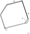
- the bottom border 3 and the top border 2 both comprise an engagement frame 21, side frames 22 installed on two sides of the engagement frame 21, and a guide rail frame 23.
- the guide rail frame 23 is installed between the two side frames 22, one side facing towards the shower area of the guide rail frame 23 is provided with a guide rail 231, and guide grooves 232 are vertically downward arranged in a top of the guide rail 231; in this embodiment, the guide grooves on the top border 2 and the bottom border 3 are opposite in direction.
- a trapezoidal groove 233 is arranged in one side of the guide rail frame 23 arranged on the second fixed glass plates 43 far away from the installing bars 45; and an installation opening 234 is arranged in one side facing towards the second fixed glass plates 43 of the trapezoidal groove 233.
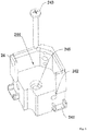
- embedded through holes 222 are horizontally arranged in bottoms of the guide rail frame 23 and the side frames 22; first expansion bars 223 are arranged on the guide rail frame 23 and the side frames 22 in clamping holes, and installing holes 224 are horizontally arranged in the first expansion bars 223.
- a positioning bulge 221 is arranged at a top of each of the side frames 22.
- the guide rail frame 23 and the side frames 22 are connected by connecting parts 24; embedded blocks 241 are arranged on two sides of the connecting parts 24; the guide rail frame 23 and the side frames 22 are positioned by the embedded through holes 222 for clamping the embedded blocks 241; countersunk holes 242 communicating with the installing holes 224 are arranged in the connecting parts 24; locking screws 243 are arranged in the countersunk holes 242, pass through the countersunk holes 242 and are in expansion connection with the first expansion bars 223.
- positioning insert blocks 211 are symmetrically arranged on two sides of a bottom of the engagement frame 21 and have the same size as the embedded blocks 241 on the connecting parts 24, wherein the positioning insert blocks 211 are inserted on the other sides of the embedding through holes 222 on the side frames 22; a positioning groove 212 vertically downward arranged in a top of the engagement frame 21 and placing grooves 213 symmetrically arranged in two sides of the positioning groove 212; and bolts connected with first expansion bars 223 on the side frames and arranged on side walls of the placing grooves 213.
- Locking through holes 214 communicating with the placing grooves 213 are arranged in a back side of the engagement frame 21, and spacing bolts 215 are installed in the locking through holes 214.
- positioning bars 411 are symmetrically arranged on two sides of the function plate 41 and clamping grooves 412 are vertically downward arranged on sides facing towards the first fixed glass plates 42 of the two positioning bars 411.
- each of the first fixed glass plates 42 includes a glass plate body and positioning profile steel installed at an edge of the glass plate body, wherein each of installing bars 45 is arranged on one side of the glass plate body.
- the installing bars 45 are fixedly installed with the other sides of the first fixed glass plates 42 and provided with locking through slots 451 and installing slots 452 perpendicular to each other.
- the first fixed glass plates 42 are clamped in the locking through slots 451 and sides of the second fixed glass plates 43 are clamped in the installing slots 452.
- installing parts 46 are arranged at bottoms of the installing bars 45 vertically installed in installing grooves 462; the installing parts 46 include installing blocks 461 at bottoms of the installing parts 46, the installing grooves 462 at tops of the installing parts 46, stop blocks 463 located at the tops, positioning through slots 464 and spacing through slots 465 vertically arranged on two sides of the installing grooves 462.
- Side walls of the installing blocks 461 are provided with a positioning plane 4611 corresponding to an installation plane 247, wherein a locking hole 4612 corresponding to the fixing hole 248 is arranged in the positioning plane 4611, and a fixed bolt 249 is in threaded connection with the fixing hole 248 and the locking hole 4612.
- a positioning groove 423 for embedding the positioning bulge 221 is arranged in a top of the positioning profile steel located at the bottom of each of the first fixed glass plates 42.
- a positioning through hole 453 is vertically arranged inside each of the installing bars 45; the stop blocks 463 are clamped in the positioning through hole 453 on each of the installing bars 45; a side wall of each of the stop blocks 463 is attached to an inner wall of the positioning through hole 453 and a second expansion bar 454 is arranged at a center of the positioning through hole 453; the installing parts 46 and the installing bars 45 are fixed by bolts and the second expansion bar 454.
- a pressing assembly 47 is arranged on one side of a bottom of the guide rail frame 23 on the second fixed glass plates 43 and far away from the first fixed glass plates 42, and installed on sides of the second fixed glass plates 43 far away from the first fixed glass plates 42, and includes a pressing member 471 for pressing each of the second fixed glass plates 43, a pressing nut 472 slidably installed in the trapezoidal groove 233, and a pressing bolt 473 for connecting the pressing member 471 and the pressing nut 472.
- the pressing nut 472 is slidably installed in the trapezoidal groove 233, and a placing hole through which the pressing nut 472 passes is horizontally arranged in the pressing member 471, wherein the pressing bolt 473 passes through the placing hole and is in threaded connection with the pressing nut 472.
- a movable glass door 44 is slidably installed between the two second fixed glass plates 43;
- a hinge assembly 48 is arranged on two sides of the movable glass door 44 and includes two pairs of hinge members installed on the two sides of the movable glass door 44 and a spacing bar 484 for connecting the hinge members on a same side.
- Each of the hinge members includes a hinge block 481, two rollers 482 and a coupling screw 483; the hinge members are installed on one side facing towards the guide rail frame 23 of the rollers 482; a hinge hole 4811 communicating with the spacing bar 484 is vertically arranged in the hinge block 481, and is internally provided with a compression spring 4812, the coupling screw 483 passes through the compression spring 4812 and the hinge hole 4811 and is in threaded connection with the spacing bar 484.
- the rollers 482 on the movable glass door 44 are embedded into the guide grooves 232 in the guide rail frame 23 on the top border 2 and the bottom border 3, so that the movable glass door 44 is installed between the top border 2 and the bottom border 3.
- one of the rollers 482 at a top of the movable glass door 44 is clamped in the guide rail frame 23 of the top border 2 and then the whole movable glass door 44 is pulled down by the compression spring 4812, so that the other of the rollers 482 at a bottom of the movable glass door 44 is clamped in the guide rail frame 23 of the bottom border 3 to install the movable glass door 44 between the top border 2 and the bottom border 3, and adjustment flexibility of the movable glass door 44 is able to be controlled by adjusting a locking extent between the locking screws 243 and the installing bars 45.
- the working principle of this embodiment is that before going to the place where the shower room needs to be installed, firstly the shower tray 1 and the bottom border are assembled into a first module; and then the glass plate assembly 4 is assembled into a second module according to a shape of the bottom border 3; finally the top border 2 is assembled into a third module; three modules are transported to an installation area after being assembled; the shower tray 1 of the first module is directly placed on the installation area, and then the glass plate assembly 4 of the second module is correspondingly placed on the bottom border 3 of the first module and installed, so that a lower end edge of the glass plate assembly 4 is in corresponding fit connection with the bottom border 3; finally, the top border 2 of the third module is correspondingly placed on an upper edge of the glass plate assembly 4 and correspondingly matched and fixedly connected.
- the whole shower room is installed by dividing three modules, so that the installation area is reduced in installation process, installation space and installation difficulty, and is improved in installation efficiency.
Landscapes
- Health & Medical Sciences (AREA)
- Public Health (AREA)
- Epidemiology (AREA)
- General Health & Medical Sciences (AREA)
- Residential Or Office Buildings (AREA)
- Securing Of Glass Panes Or The Like (AREA)
Claims (9)
- Zusammengesetzter Duschraum, umfassend: eine Duschwanne (1), einen oberen Rand (2), einen unteren Rand (3), der fest an der Duschwanne (1) angeordnet ist, und eine Glasplattenanordnung (4), die zwischen dem oberen Rand (2) und dem unteren Rand (3) angeordnet ist,
wobei die Glasplattenanordnung (4) eine Funktionsplatte (41), erste feststehende Glasplatten (42), die mit zwei Seiten der Funktionsplatte (41) verbunden sind, zweite feststehende Glasplatten (43), die mit den anderen Seiten der ersten feststehenden Glasplatten (42) verbunden sind, und eine bewegliche Glastür (44) umfasst; wobei die Funktionsplatte (41), die ersten feststehenden Glasplatten (42), die zweiten feststehenden Glasplatten (43) und die bewegliche Glastür (44) Ende an Ende verbunden sind, um einen Duschbereich zu bilden; und
wobei die untere Umrandung (3) und die obere Umrandung (2) beide einen Eingriffsrahmen (21), einen Führungsschienenrahmen (23) und Seitenrahmen (22) umfassen, die an zwei Seiten des Eingriffsrahmens (21) angeordnet sind; zwei Enden des Führungsschienenrahmens (23) sind mit Enden von zwei Seitenrahmen (22) verbunden, die von dem Eingriffsrahmen (23) weit entfernt angeordnet sind; wobei der Führungsschienenrahmen (23) und die Seitenrahmen (22) durch Verbindungsteile (24) verbunden sind, und wobei die Verbindungsteile (24) an der Duschwanne (1) befestigt sind. - Zusammengesetzter Duschraum nach Anspruch 1, dadurch gekennzeichnet, dass die Verbindungsteile (24) mit beidseitig angeordneten Einbettungsklötzen (241) versehen sind; wobei in dem Führungsschienenrahmen (23) und den Seitenrahmen (22) eingebettete Durchgangslöcher (222) zum Festklemmen der Einbettungsklötze (241) angeordnet sind; wobei oberhalb der Einbettungsklötze (241) an dem Führungsschienenrahmen (23) und den Seitenrahmen (22) erste Spreizstäbe (223) angeordnet sind; wobei Montagelöcher (224) horizontal in den ersten Spreizstäben (223) angeordnet sind und Senkbohrungen (242), die mit den Montagelöchern (224) in Verbindung stehen, in den Verbindungsteilen (24) angeordnet sind; und wobei Sicherungsschrauben (243) in den Senkbohrungen (242) angeordnet sind und durch die Senkbohrungen (242) hindurchgehen und mit den ersten Spreizstäben (223) stehen.
- Zusammengesetzter Duschraum nach Anspruch 2, dadurch gekennzeichnet, dass Positioniereinsatzblöcke (211) symmetrisch an den beiden Seiten des Eingriffsrahmens (21) angeordnet, in den eingelassenen Durchgangslöchern (222) geklemmt und mit den ersten Spreizstäben (223) an den Seitenrahmen (22) durch Bolzen verbunden sind.
- Zusammengesetzter Duschraum nach Anspruch 1, dadurch gekennzeichnet, dass in der Funktionsplatte (41) Klemmnuten (412) zum Einspannen der ersten feststehenden Glasplatten (42) angeordnet sind und die ersten feststehenden Glasplatten (42) in den Klemmnuten (412) eingespannt sind.
- Zusammengesetzter Duschraum nach Anspruch 1, dadurch gekennzeichnet, dass jede der ersten feststehenden Glasplatten (42) einen Glasscheibenkörper aufweist; wobei an Seitenwänden des ersten Festglasscheibenkörpers Montagestangen (45) angeordnet sind, die mit Montageschlitzen (452) zum Einsetzen der zweiten feststehenden Glasplatten (43) versehen sind; und Seitenwände der zweiten feststehenden Glasplatten (43) in die Montageschlitze (452) eingesetzt sind.
- Zusammengesetzter Duschraum nach Anspruch 1, dadurch gekennzeichnet, dass eine Oberseite des Eingriffsrahmens (21) mit einer Positionierungsnut (212) versehen ist, in die die Funktionsplatte (41) eingesetzt ist.
- Zusammengesetzter Duschraum nach Anspruch 1, dadurch gekennzeichnet, dass die ersten feststehenden Glasplatten (42) ferner Positionierungsprofilstahl umfassen, der an einer Kante des Glasplattenkörpers installiert ist; wobei ein Positionierungswulst (221) an einer Oberseite jedes der Seitenrahmen (22) angeordnet ist; und eine Positionierungsnut (423) zum Einbetten des Positionierungswulstes (221) an einer Oberseite des Positionierungsprofilstahls angeordnet ist, der an einer Unterseite jeder der ersten feststehenden Glasplatten (42) positioniert ist.
- Zusammengesetzter Duschraum nach Anspruch 1, dadurch gekennzeichnet, dass an den Unterseiten der Montagestangen (45) Einbauteile (46) angeordnet sind; wobei in einer Oberseite der Verbindungsteile (24) jeweils ein Abstandsschlitz (244) angeordnet ist und an den Unterseiten der Einbauteile (46) Einbaublöcke (461) angeordnet sind, die in den Abstandsschlitz (244) eingesetzt sind.
- Zusammengesetzter Duschraum nach Anspruch 5, dadurch gekennzeichnet, dass an einer Unterseite des Führungsschienenrahmens (23) eine Anpressbaugruppe (47) angeordnet ist, die auf den von den ersten feststehenden Glasplatten (42) abgewandten Seiten der zweiten feststehenden Glasplatten (43) installiert ist und ein Anpresselement (471) zum Anpressen jeder der zweiten feststehenden Glasplatten (43) aufweist; eine trapezförmige Nut (233) in einer Seite des Führungsschienenrahmens (23) angeordnet ist, die auf den zweiten feststehenden Glasplatten (43) entfernt von den Montagestangen angeordnet ist; und eine Installationsöffnung (234) auf einer Seite angeordnet ist, die den zweiten feststehenden Glasplatten (43) der trapezförmigen Nut (233) zugewandt ist; wobei die Pressanordnung (47) ferner eine Pressmutter (472), die verschiebbar in der trapezförmigen Nut (233) installiert ist, und einen Pressbolzen (473) zum Verbinden des Pressglieds (471) und der Pressmutter (472) umfasst.
Applications Claiming Priority (1)
| Application Number | Priority Date | Filing Date | Title |
|---|---|---|---|
| CN201920717732.0U CN210918347U (zh) | 2019-05-17 | 2019-05-17 | 一种装配式淋浴房 |
Publications (2)
| Publication Number | Publication Date |
|---|---|
| EP3738488A1 EP3738488A1 (de) | 2020-11-18 |
| EP3738488B1 true EP3738488B1 (de) | 2021-03-03 |
Family
ID=66826862
Family Applications (1)
| Application Number | Title | Priority Date | Filing Date |
|---|---|---|---|
| EP19179587.1A Active EP3738488B1 (de) | 2019-05-17 | 2019-06-12 | Montierter duschraum |
Country Status (3)
| Country | Link |
|---|---|
| EP (1) | EP3738488B1 (de) |
| CN (1) | CN210918347U (de) |
| DK (1) | DK3738488T3 (de) |
Families Citing this family (4)
| Publication number | Priority date | Publication date | Assignee | Title |
|---|---|---|---|---|
| CN113250408B (zh) * | 2021-05-18 | 2024-07-12 | 浙江亚厦装饰股份有限公司 | 一种装配式整体卫浴房用密封框结构 |
| CN114108842B (zh) * | 2021-12-16 | 2024-04-02 | 中山市福瑞卫浴设备有限公司 | 一种淋浴房的预埋结构 |
| CN114109090B (zh) * | 2021-12-23 | 2023-06-16 | 中山市福瑞卫浴设备有限公司 | 一种新型淋浴房的下挡水结构及淋浴房 |
| CN115405203B (zh) * | 2022-09-09 | 2024-05-24 | 宁波市广和洁具有限公司 | 一种快装式淋浴房及安装方法 |
Family Cites Families (3)
| Publication number | Priority date | Publication date | Assignee | Title |
|---|---|---|---|---|
| DE3101947A1 (de) * | 1981-01-22 | 1982-08-05 | Heinz Georg 3626 Hünibach Thun Baus | Duschtrennwand |
| CN201879580U (zh) * | 2010-11-20 | 2011-06-29 | 徐伟 | 一种简易装拆的淋浴房 |
| CN105662219B (zh) | 2016-03-09 | 2018-11-20 | 平湖市欧文洁具有限公司 | 一种淋浴房 |
-
2019
- 2019-05-17 CN CN201920717732.0U patent/CN210918347U/zh active Active
- 2019-06-12 DK DK19179587.1T patent/DK3738488T3/da active
- 2019-06-12 EP EP19179587.1A patent/EP3738488B1/de active Active
Non-Patent Citations (1)
| Title |
|---|
| None * |
Also Published As
| Publication number | Publication date |
|---|---|
| DK3738488T3 (da) | 2021-03-22 |
| CN210918347U (zh) | 2020-07-03 |
| EP3738488A1 (de) | 2020-11-18 |
Similar Documents
| Publication | Publication Date | Title |
|---|---|---|
| EP3738488A1 (de) | Montierter duschraum | |
| EP2570011B1 (de) | Gangeinschlusssystem | |
| US6681536B1 (en) | Mounting structure and method for viscosity system damping wall | |
| CN114961146B (zh) | 装配式墙板系统及安装方法 | |
| CN215760125U (zh) | 一种装配式墙板系统 | |
| CN211831432U (zh) | 一种建筑施工用的拼接式电气柜 | |
| KR100845459B1 (ko) | 콘크리트 보 패널의 지지장치 | |
| CN111779291A (zh) | 一种可减少墙面完成面的构件及其安装方式 | |
| CN212562569U (zh) | 一种可减少墙面完成面的构件 | |
| CN207070495U (zh) | 一种机柜及其主框架和侧板 | |
| CN216475782U (zh) | 幕墙连接件 | |
| CN109440977B (zh) | 一种模块化阳光房墙体单元及其装配方法 | |
| CN220693067U (zh) | 一种易组装组件的光伏边框 | |
| CN222810278U (zh) | 一种安全性高的幕墙结构 | |
| CN210636726U (zh) | 一种铝蜂窝板拼接结构 | |
| CN217723019U (zh) | 一种抽屉面板快装治具 | |
| CN218657138U (zh) | 套筒侧面开窗用加工辅助装置 | |
| CN222010000U (zh) | 一种便于玻璃安装的复合型铝合金门窗 | |
| CN212836107U (zh) | 一种模块化的拼接墙板 | |
| CN218293284U (zh) | 一种内外均可安装的单元窗系统 | |
| CN220848471U (zh) | 一种可快速固定的板材 | |
| CN220234577U (zh) | 一种光伏组件可调安装结构 | |
| CN214838933U (zh) | 一种预制可调节装配式供热管道固定墩 | |
| CN221002478U (zh) | 一种互扣安装u型玻璃组件的上口铝框结构 | |
| CN219671759U (zh) | 一种方便拆装的玻璃隔断 |
Legal Events
| Date | Code | Title | Description |
|---|---|---|---|
| PUAI | Public reference made under article 153(3) epc to a published international application that has entered the european phase |
Free format text: ORIGINAL CODE: 0009012 |
|
| STAA | Information on the status of an ep patent application or granted ep patent |
Free format text: STATUS: REQUEST FOR EXAMINATION WAS MADE |
|
| 17P | Request for examination filed |
Effective date: 20190612 |
|
| AK | Designated contracting states |
Kind code of ref document: A1 Designated state(s): AL AT BE BG CH CY CZ DE DK EE ES FI FR GB GR HR HU IE IS IT LI LT LU LV MC MK MT NL NO PL PT RO RS SE SI SK SM TR |
|
| AX | Request for extension of the european patent |
Extension state: BA ME |
|
| RBV | Designated contracting states (corrected) |
Designated state(s): AL AT BE BG CH CY CZ DE DK EE ES FI FR GB GR HR HU IE IS IT LI LT LU LV MC MK MT NL NO PL PT RO RS SE SI SK SM TR |
|
| GRAP | Despatch of communication of intention to grant a patent |
Free format text: ORIGINAL CODE: EPIDOSNIGR1 |
|
| STAA | Information on the status of an ep patent application or granted ep patent |
Free format text: STATUS: GRANT OF PATENT IS INTENDED |
|
| INTG | Intention to grant announced |
Effective date: 20201221 |
|
| GRAS | Grant fee paid |
Free format text: ORIGINAL CODE: EPIDOSNIGR3 |
|
| GRAA | (expected) grant |
Free format text: ORIGINAL CODE: 0009210 |
|
| STAA | Information on the status of an ep patent application or granted ep patent |
Free format text: STATUS: THE PATENT HAS BEEN GRANTED |
|
| AK | Designated contracting states |
Kind code of ref document: B1 Designated state(s): AL AT BE BG CH CY CZ DE DK EE ES FI FR GB GR HR HU IE IS IT LI LT LU LV MC MK MT NL NO PL PT RO RS SE SI SK SM TR |
|
| REG | Reference to a national code |
Ref country code: GB Ref legal event code: FG4D |
|
| REG | Reference to a national code |
Ref country code: CH Ref legal event code: EP Ref country code: AT Ref legal event code: REF Ref document number: 1366279 Country of ref document: AT Kind code of ref document: T Effective date: 20210315 |
|
| REG | Reference to a national code |
Ref country code: DK Ref legal event code: T3 Effective date: 20210317 |
|
| REG | Reference to a national code |
Ref country code: FI Ref legal event code: FGE |
|
| REG | Reference to a national code |
Ref country code: DE Ref legal event code: R096 Ref document number: 602019002900 Country of ref document: DE |
|
| REG | Reference to a national code |
Ref country code: IE Ref legal event code: FG4D |
|
| REG | Reference to a national code |
Ref country code: SE Ref legal event code: TRGR |
|
| REG | Reference to a national code |
Ref country code: NO Ref legal event code: T2 Effective date: 20210303 |
|
| REG | Reference to a national code |
Ref country code: LT Ref legal event code: MG9D |
|
| PG25 | Lapsed in a contracting state [announced via postgrant information from national office to epo] |
Ref country code: LT Free format text: LAPSE BECAUSE OF FAILURE TO SUBMIT A TRANSLATION OF THE DESCRIPTION OR TO PAY THE FEE WITHIN THE PRESCRIBED TIME-LIMIT Effective date: 20210303 Ref country code: BG Free format text: LAPSE BECAUSE OF FAILURE TO SUBMIT A TRANSLATION OF THE DESCRIPTION OR TO PAY THE FEE WITHIN THE PRESCRIBED TIME-LIMIT Effective date: 20210603 Ref country code: HR Free format text: LAPSE BECAUSE OF FAILURE TO SUBMIT A TRANSLATION OF THE DESCRIPTION OR TO PAY THE FEE WITHIN THE PRESCRIBED TIME-LIMIT Effective date: 20210303 Ref country code: GR Free format text: LAPSE BECAUSE OF FAILURE TO SUBMIT A TRANSLATION OF THE DESCRIPTION OR TO PAY THE FEE WITHIN THE PRESCRIBED TIME-LIMIT Effective date: 20210604 |
|
| REG | Reference to a national code |
Ref country code: NL Ref legal event code: MP Effective date: 20210303 |
|
| REG | Reference to a national code |
Ref country code: AT Ref legal event code: MK05 Ref document number: 1366279 Country of ref document: AT Kind code of ref document: T Effective date: 20210303 |
|
| PG25 | Lapsed in a contracting state [announced via postgrant information from national office to epo] |
Ref country code: LV Free format text: LAPSE BECAUSE OF FAILURE TO SUBMIT A TRANSLATION OF THE DESCRIPTION OR TO PAY THE FEE WITHIN THE PRESCRIBED TIME-LIMIT Effective date: 20210303 Ref country code: PL Free format text: LAPSE BECAUSE OF FAILURE TO SUBMIT A TRANSLATION OF THE DESCRIPTION OR TO PAY THE FEE WITHIN THE PRESCRIBED TIME-LIMIT Effective date: 20210303 Ref country code: RS Free format text: LAPSE BECAUSE OF FAILURE TO SUBMIT A TRANSLATION OF THE DESCRIPTION OR TO PAY THE FEE WITHIN THE PRESCRIBED TIME-LIMIT Effective date: 20210303 |
|
| PG25 | Lapsed in a contracting state [announced via postgrant information from national office to epo] |
Ref country code: NL Free format text: LAPSE BECAUSE OF FAILURE TO SUBMIT A TRANSLATION OF THE DESCRIPTION OR TO PAY THE FEE WITHIN THE PRESCRIBED TIME-LIMIT Effective date: 20210303 |
|
| PG25 | Lapsed in a contracting state [announced via postgrant information from national office to epo] |
Ref country code: SM Free format text: LAPSE BECAUSE OF FAILURE TO SUBMIT A TRANSLATION OF THE DESCRIPTION OR TO PAY THE FEE WITHIN THE PRESCRIBED TIME-LIMIT Effective date: 20210303 Ref country code: AT Free format text: LAPSE BECAUSE OF FAILURE TO SUBMIT A TRANSLATION OF THE DESCRIPTION OR TO PAY THE FEE WITHIN THE PRESCRIBED TIME-LIMIT Effective date: 20210303 Ref country code: CZ Free format text: LAPSE BECAUSE OF FAILURE TO SUBMIT A TRANSLATION OF THE DESCRIPTION OR TO PAY THE FEE WITHIN THE PRESCRIBED TIME-LIMIT Effective date: 20210303 Ref country code: EE Free format text: LAPSE BECAUSE OF FAILURE TO SUBMIT A TRANSLATION OF THE DESCRIPTION OR TO PAY THE FEE WITHIN THE PRESCRIBED TIME-LIMIT Effective date: 20210303 |
|
| PG25 | Lapsed in a contracting state [announced via postgrant information from national office to epo] |
Ref country code: IS Free format text: LAPSE BECAUSE OF FAILURE TO SUBMIT A TRANSLATION OF THE DESCRIPTION OR TO PAY THE FEE WITHIN THE PRESCRIBED TIME-LIMIT Effective date: 20210703 Ref country code: RO Free format text: LAPSE BECAUSE OF FAILURE TO SUBMIT A TRANSLATION OF THE DESCRIPTION OR TO PAY THE FEE WITHIN THE PRESCRIBED TIME-LIMIT Effective date: 20210303 Ref country code: PT Free format text: LAPSE BECAUSE OF FAILURE TO SUBMIT A TRANSLATION OF THE DESCRIPTION OR TO PAY THE FEE WITHIN THE PRESCRIBED TIME-LIMIT Effective date: 20210705 Ref country code: SK Free format text: LAPSE BECAUSE OF FAILURE TO SUBMIT A TRANSLATION OF THE DESCRIPTION OR TO PAY THE FEE WITHIN THE PRESCRIBED TIME-LIMIT Effective date: 20210303 |
|
| REG | Reference to a national code |
Ref country code: DE Ref legal event code: R097 Ref document number: 602019002900 Country of ref document: DE |
|
| PLBE | No opposition filed within time limit |
Free format text: ORIGINAL CODE: 0009261 |
|
| STAA | Information on the status of an ep patent application or granted ep patent |
Free format text: STATUS: NO OPPOSITION FILED WITHIN TIME LIMIT |
|
| PG25 | Lapsed in a contracting state [announced via postgrant information from national office to epo] |
Ref country code: ES Free format text: LAPSE BECAUSE OF FAILURE TO SUBMIT A TRANSLATION OF THE DESCRIPTION OR TO PAY THE FEE WITHIN THE PRESCRIBED TIME-LIMIT Effective date: 20210303 Ref country code: AL Free format text: LAPSE BECAUSE OF FAILURE TO SUBMIT A TRANSLATION OF THE DESCRIPTION OR TO PAY THE FEE WITHIN THE PRESCRIBED TIME-LIMIT Effective date: 20210303 Ref country code: MC Free format text: LAPSE BECAUSE OF FAILURE TO SUBMIT A TRANSLATION OF THE DESCRIPTION OR TO PAY THE FEE WITHIN THE PRESCRIBED TIME-LIMIT Effective date: 20210303 |
|
| 26N | No opposition filed |
Effective date: 20211206 |
|
| REG | Reference to a national code |
Ref country code: BE Ref legal event code: MM Effective date: 20210630 |
|
| PG25 | Lapsed in a contracting state [announced via postgrant information from national office to epo] |
Ref country code: LU Free format text: LAPSE BECAUSE OF NON-PAYMENT OF DUE FEES Effective date: 20210612 |
|
| PG25 | Lapsed in a contracting state [announced via postgrant information from national office to epo] |
Ref country code: IT Free format text: LAPSE BECAUSE OF FAILURE TO SUBMIT A TRANSLATION OF THE DESCRIPTION OR TO PAY THE FEE WITHIN THE PRESCRIBED TIME-LIMIT Effective date: 20210303 Ref country code: IE Free format text: LAPSE BECAUSE OF NON-PAYMENT OF DUE FEES Effective date: 20210612 |
|
| PG25 | Lapsed in a contracting state [announced via postgrant information from national office to epo] |
Ref country code: IS Free format text: LAPSE BECAUSE OF FAILURE TO SUBMIT A TRANSLATION OF THE DESCRIPTION OR TO PAY THE FEE WITHIN THE PRESCRIBED TIME-LIMIT Effective date: 20210703 Ref country code: FR Free format text: LAPSE BECAUSE OF NON-PAYMENT OF DUE FEES Effective date: 20210630 |
|
| PG25 | Lapsed in a contracting state [announced via postgrant information from national office to epo] |
Ref country code: BE Free format text: LAPSE BECAUSE OF NON-PAYMENT OF DUE FEES Effective date: 20210630 |
|
| REG | Reference to a national code |
Ref country code: CH Ref legal event code: PL |
|
| PG25 | Lapsed in a contracting state [announced via postgrant information from national office to epo] |
Ref country code: LI Free format text: LAPSE BECAUSE OF NON-PAYMENT OF DUE FEES Effective date: 20220630 Ref country code: CH Free format text: LAPSE BECAUSE OF NON-PAYMENT OF DUE FEES Effective date: 20220630 |
|
| PG25 | Lapsed in a contracting state [announced via postgrant information from national office to epo] |
Ref country code: CY Free format text: LAPSE BECAUSE OF FAILURE TO SUBMIT A TRANSLATION OF THE DESCRIPTION OR TO PAY THE FEE WITHIN THE PRESCRIBED TIME-LIMIT Effective date: 20210303 |
|
| PG25 | Lapsed in a contracting state [announced via postgrant information from national office to epo] |
Ref country code: HU Free format text: LAPSE BECAUSE OF FAILURE TO SUBMIT A TRANSLATION OF THE DESCRIPTION OR TO PAY THE FEE WITHIN THE PRESCRIBED TIME-LIMIT; INVALID AB INITIO Effective date: 20190612 |
|
| PG25 | Lapsed in a contracting state [announced via postgrant information from national office to epo] |
Ref country code: SI Free format text: LAPSE BECAUSE OF FAILURE TO SUBMIT A TRANSLATION OF THE DESCRIPTION OR TO PAY THE FEE WITHIN THE PRESCRIBED TIME-LIMIT Effective date: 20210303 |
|
| GBPC | Gb: european patent ceased through non-payment of renewal fee |
Effective date: 20230612 |
|
| PG25 | Lapsed in a contracting state [announced via postgrant information from national office to epo] |
Ref country code: MK Free format text: LAPSE BECAUSE OF FAILURE TO SUBMIT A TRANSLATION OF THE DESCRIPTION OR TO PAY THE FEE WITHIN THE PRESCRIBED TIME-LIMIT Effective date: 20210303 Ref country code: GB Free format text: LAPSE BECAUSE OF NON-PAYMENT OF DUE FEES Effective date: 20230612 |
|
| PG25 | Lapsed in a contracting state [announced via postgrant information from national office to epo] |
Ref country code: MT Free format text: LAPSE BECAUSE OF FAILURE TO SUBMIT A TRANSLATION OF THE DESCRIPTION OR TO PAY THE FEE WITHIN THE PRESCRIBED TIME-LIMIT Effective date: 20210303 |
|
| PGFP | Annual fee paid to national office [announced via postgrant information from national office to epo] |
Ref country code: FI Payment date: 20250627 Year of fee payment: 7 |
|
| PGFP | Annual fee paid to national office [announced via postgrant information from national office to epo] |
Ref country code: DE Payment date: 20250618 Year of fee payment: 7 |
|
| PGFP | Annual fee paid to national office [announced via postgrant information from national office to epo] |
Ref country code: DK Payment date: 20250625 Year of fee payment: 7 |
|
| PGFP | Annual fee paid to national office [announced via postgrant information from national office to epo] |
Ref country code: NO Payment date: 20250624 Year of fee payment: 7 |
|
| PGFP | Annual fee paid to national office [announced via postgrant information from national office to epo] |
Ref country code: SE Payment date: 20250618 Year of fee payment: 7 |
|
| PG25 | Lapsed in a contracting state [announced via postgrant information from national office to epo] |
Ref country code: TR Free format text: LAPSE BECAUSE OF FAILURE TO SUBMIT A TRANSLATION OF THE DESCRIPTION OR TO PAY THE FEE WITHIN THE PRESCRIBED TIME-LIMIT Effective date: 20210303 |