EP3737248B1 - Mundstückanordnung für eine inhalationsvorrichtung mit einer austauschbaren substratkomponente und austauschbare substratkomponente dafür - Google Patents
Mundstückanordnung für eine inhalationsvorrichtung mit einer austauschbaren substratkomponente und austauschbare substratkomponente dafür Download PDFInfo
- Publication number
- EP3737248B1 EP3737248B1 EP19700659.6A EP19700659A EP3737248B1 EP 3737248 B1 EP3737248 B1 EP 3737248B1 EP 19700659 A EP19700659 A EP 19700659A EP 3737248 B1 EP3737248 B1 EP 3737248B1
- Authority
- EP
- European Patent Office
- Prior art keywords
- mouthpiece
- substrate component
- substrate
- assembly
- component
- Prior art date
- Legal status (The legal status is an assumption and is not a legal conclusion. Google has not performed a legal analysis and makes no representation as to the accuracy of the status listed.)
- Active
Links
Images


Classifications
-
- A—HUMAN NECESSITIES
- A24—TOBACCO; CIGARS; CIGARETTES; SIMULATED SMOKING DEVICES; SMOKERS' REQUISITES
- A24F—SMOKERS' REQUISITES; MATCH BOXES; SIMULATED SMOKING DEVICES
- A24F40/00—Electrically operated smoking devices; Component parts thereof; Manufacture thereof; Maintenance or testing thereof; Charging means specially adapted therefor
- A24F40/40—Constructional details, e.g. connection of cartridges and battery parts
-
- A—HUMAN NECESSITIES
- A24—TOBACCO; CIGARS; CIGARETTES; SIMULATED SMOKING DEVICES; SMOKERS' REQUISITES
- A24F—SMOKERS' REQUISITES; MATCH BOXES; SIMULATED SMOKING DEVICES
- A24F40/00—Electrically operated smoking devices; Component parts thereof; Manufacture thereof; Maintenance or testing thereof; Charging means specially adapted therefor
- A24F40/10—Devices using liquid inhalable precursors
-
- A—HUMAN NECESSITIES
- A24—TOBACCO; CIGARS; CIGARETTES; SIMULATED SMOKING DEVICES; SMOKERS' REQUISITES
- A24F—SMOKERS' REQUISITES; MATCH BOXES; SIMULATED SMOKING DEVICES
- A24F40/00—Electrically operated smoking devices; Component parts thereof; Manufacture thereof; Maintenance or testing thereof; Charging means specially adapted therefor
- A24F40/40—Constructional details, e.g. connection of cartridges and battery parts
- A24F40/42—Cartridges or containers for inhalable precursors
-
- A—HUMAN NECESSITIES
- A24—TOBACCO; CIGARS; CIGARETTES; SIMULATED SMOKING DEVICES; SMOKERS' REQUISITES
- A24F—SMOKERS' REQUISITES; MATCH BOXES; SIMULATED SMOKING DEVICES
- A24F40/00—Electrically operated smoking devices; Component parts thereof; Manufacture thereof; Maintenance or testing thereof; Charging means specially adapted therefor
- A24F40/40—Constructional details, e.g. connection of cartridges and battery parts
- A24F40/46—Shape or structure of electric heating means
-
- A—HUMAN NECESSITIES
- A24—TOBACCO; CIGARS; CIGARETTES; SIMULATED SMOKING DEVICES; SMOKERS' REQUISITES
- A24F—SMOKERS' REQUISITES; MATCH BOXES; SIMULATED SMOKING DEVICES
- A24F40/00—Electrically operated smoking devices; Component parts thereof; Manufacture thereof; Maintenance or testing thereof; Charging means specially adapted therefor
- A24F40/40—Constructional details, e.g. connection of cartridges and battery parts
- A24F40/48—Fluid transfer means, e.g. pumps
- A24F40/485—Valves; Apertures
-
- A—HUMAN NECESSITIES
- A24—TOBACCO; CIGARS; CIGARETTES; SIMULATED SMOKING DEVICES; SMOKERS' REQUISITES
- A24F—SMOKERS' REQUISITES; MATCH BOXES; SIMULATED SMOKING DEVICES
- A24F42/00—Simulated smoking devices other than electrically operated; Component parts thereof; Manufacture or testing thereof
- A24F42/60—Constructional details
-
- A—HUMAN NECESSITIES
- A24—TOBACCO; CIGARS; CIGARETTES; SIMULATED SMOKING DEVICES; SMOKERS' REQUISITES
- A24F—SMOKERS' REQUISITES; MATCH BOXES; SIMULATED SMOKING DEVICES
- A24F7/00—Mouthpieces for pipes; Mouthpieces for cigar or cigarette holders
Definitions
- the present invention relates to a mouthpiece assembly for an inhalation device including a replaceable substrate component, and a replaceable substrate component therefor. More specifically, the invention relates to a mouthpiece assembly for an inhalation device which is adapted to receive a replaceable substrate component capable of receiving a source of energy by means of which the substrate itself, or an energisable element applied thereto or formed therewith, may be excited, such excitation being sufficient to cause an amount of a suitable formulation or a constituent composition therein and having been deposited on a surface of said substrate component, to be at least partially aerosolized, atomized, vaporised, gasefied or otherwise promoted into the ambient atmosphere surrounding it within the mouthpiece.
- the invention relates to a mouthpiece assembly including such a substrate component and which is provided with at least air inlet and outlet regions and within which, by means of suction pressure most commonly applied by a user's mouth at the outlet region, air is caused to flow from the inlet region towards the outlet region through at least one conduit defined within said mouthpiece assembly and/or said substrate component and at least some part of which is in communication with ambient air above that portion of the substrate component on which the amount of formulation has been deposited and which may thus be entrained into said air flow.
- the present invention is concerned with what have become known as Electronic Nicotine Delivery Systems (ENDS, herein being both singular and plural as required by context), and in this regard the formulation which is deposited on the substrate component will most typically be a nicotine-containing formulation.
- ETS Electronic Nicotine Delivery Systems
- the skilled reader will understand that this need not be the case, and that the present invention is not limited by the specific formulation deposited on the substrate component, except that it should be aerosolizable at least to some extent upon receiving an excitation energy.
- the excitation energy is exclusively electrical
- the energisable element forming part of the substrate component is an electrically resistive heating element, but again of course this need not be the case, and the skilled reader is to understand that the present invention is not particularly concerned with either the manner of excitation or with the excitation energy per se , and is more concerned with the specific configuration of both the substrate component and the mouthpiece assembly into which it may be replaceably inserted, and how the two cooperate, particularly in the context of air flow through the mouthpiece assembly, to deliver an inhalable mixture of air and aerosolized formulation (or some constituent or derivative thereof).
- any use herein of the term "aerosolize” or any cognate expression is to be interpreted as encompassing any physical process whereby the formulation, or any constituent composition or derivative thereof, is promoted into the surrounding atmosphere, in any phase, i.e. as a gas, a liquid, or a solid, or any phase intermediate thereof, and the meaning of such term or terms could therefore extend any one or more of: atomization, vapourisation, gasification, nebulisation, to name but a few.
- ENDS have been in widespread use now for some years, and although there has been and continues to be little concrete scientific evidence as to how harmful they are to human health, in particular human lungs, it is largely beyond doubt that the use of any ENDS is significantly less harmful than the smoking of combustible tobacco products, such as cigarettes, cigars, cigarillos, pipes, and hand rolling tobacco.
- the chemically active substance is nicotine (C 10 H 14 N 2 ), a potent parasympathomimetic stimulant and alkaloid.
- nicotine is a drug and like many drugs, it is highly addictive to humans.
- nicotine is also highly toxic to humans, and although nicotine only constitutes approxi mately 0.6-3.0% of the dry weight of tobacco depending on strain, variety and processing techniques, mere ingestion of only one or two cigarettes, in which there might be as much as 50mg of nicotine and possibly more, can cause quite serious toxic reactions.
- the dose of nicotine administered by an ENDS is of critical importance - in general, the dose must be sufficient to satisfy the physiological cravings experienced by users addicted to nicotine, but (ideally) less than that which is typically delivered by a corresponding combustible tobacco product in a similar time scale so that the ENDS can be effective, at least partially, in reducing an addict's dependency on the drug and thus function as a smoking cessation aid.
- wick-and-coil devices wherein an electrical heating coil is disposed adjacent, around, within or otherwise proximate a moisture absorbent wick such that a nicotine-containing liquid extant within the wick is heated sufficiently rapidly and to a sufficient degree to cause at least some of that liquid and/or one or more of its constituents to be aerosolized from the wick into the surrounding air in a gaseous or quasi-gaseous phase.
- the rechargeable battery which may be either an integral part of the device as a whole, or (more commonly) a removable and/or detachable component thereof, but in any event, the cartomizer, and thus the heating coil is electrically connected to the battery and a simple switch is provided in a convenient location on the device so that the user can selectively apply and remove electrical current to and from the heating coil and essentially activate the device.
- An example prior art cartomizer is depicted in Figure 1 hereof, and is described more fully below in the specific description hereof.
- the heating coils themselves are rather crude and rudimentary, and although some of the more modern ENDS devices include control circuitry which allows for a reduced current to be supplied to the heating coil for a brief period ( ⁇ 1s) prior to full activation of the heating element so that the coil can be pre-heated to some extent before then supplying a much larger current to the coil to heat it to the required extent for aerosolisation to occur, the aerosolisation itself is still a largely uncontrolled and certainly highly variable process, particularly in terms of the constituents of the aerosol and the particular phases (gas, liquid, solid or any intermediate thereof) in which such constituents may be present in said aerosol.
- boiling points of common carrier chemicals of which modern so-called “e-liquids” are primarily constituted are in the range of 180-290 deg.C, (PEG, with apprx. 4000-6000 mol. weight, boils at 240-260 deg.C, glycerol boils at around 290 deg.C, propylene glycol at around 188 deg.C), the skilled reader will understand that if a wick-and-coil ENDS is to function at all, then the primary requirement is that the heating coil be sufficiently responsive and capable of rising to that temperature practically instantaneously, or at least in the short time (e.g.
- the actual quantity of nicotine present in an inhaled aerosol is of critical importance, firstly and most obviously because that amount directly represents the amount of the drug being administered to the human per inhalation, and secondly and more subtly, the amount of nicotine present in the aerosol is directly correlated to the tolerability of the aerosol to be inhaled.
- the tolerability of an inhaled aerosol is a rather qualitative indication of the extent to which that aerosol, or more precisely the nicotine within it, aggravates the mucosal and buccal receptors at the entrance of and within the throat.
- a further and rather less well known aspect of tolerability is that the abovementioned receptors become progressively de-sensitised with each successive inhalation in a typical set (usually about 6-8) of multiple inhalations which are undertaken in a relatively short time period (e.g. 5 min.) when a user smokes either a conventional tobacco product such as a cigarette, or the aerosols produced by ENDS. Furthermore, it is known that the sensitivity of said receptors recovers after a user undertakes all the inhalations within such a set and undertakes no further inhalation for a period of about 30-45mins.
- the first inhalation in any set of inhalations may seem particularly harsh in the throat of a user, whereas subsequent inhalations may be comparatively mild or become progressively so, in some cases to the extent that the user barely notices any difference between the inhalation of the aerosol and an inhalation of plain air.
- the volumetric quantity of carrier compound e.g. from the 1ml or so that may be soaked throughout the wick of common ENDS to the order of a few 10s or 100s of ⁇ l present in one or two globules applied to the substrate
- the concentration of nicotine is correspondingly increased and the heat delivered to those globules is such that sufficient aerosolisation of the formulation and the nicotine within it still occurs, and that the concentration of nicotine within the now much smaller volume of aerosol remains essentially the same, i.e. enough to sate a user's craving for nicotine over a complete set of inhalations.
- This invention is particularly concerned with the airflows over and around the substrate component, and it is thus a further object of this invention to provide a mouthpiece assembly for an ENDS which not only provides a degree of air resistance, but which also has the benefit of at least partially improving the tolerability of the aerosols produced by the ENDS, particularly when the volume of aerosol produced thereby during any single activation is relatively small compared the voluminous plumes produced by wick-and-coil ENDS and which thus more effectively mask molecular nicotine present therein.
- a mouthpiece assembly for an inhalation device, and a substrate component for use as part of such a mouthpiece assembly as prescribed in claims hereof.
- conduits can simultaneously act as a means of providing a resistance to such fluid flow such that there is a requirement for a user to exert a suction pressure similar to that applied by smokers of conventional tobacco products so that utilising the mouthpiece of the present invention is, physically at least, very similar to smoking a conventional tobacco product.
- the mouthpiece and the substrate component are separate and separable entities in that the substrate component is replaceably insertable and removable from within the mouthpiece.
- the substrate component is provided with two channel formations or interior conduits, such being preferably linear and parallel in configuration and orientation.
- the substantially planar surface of the substrate component and the corresponding interior surface of the mouthpiece cooperate together to direct any and all of any fluid flow occurring within the mouthpiece component into the at least one conduit, as defined by both the said at least one channel formation and a corresponding interior surface of the said mouthpiece.
- the mouthpiece is provided interiorly with at least one secondary conduit which acts as a fluid bypass in that any fluid flow within the mouthpiece, although initially unitary in that the fluid flow into the mouthpiece through the inlet thereof is a single fluid flow, thereafter it divides into in at least two discrete parts, a first active part which is constrained to flow into the conduit provided in, or partially defined by, the substrate component and thus entrain any formulation on the substrate of the substrate component at that time being aerosolised, and a second bypass part which is separate and distinct from the first part and segregated from it for a majority of travel within the mouthpiece.
- said first active and second bypass parts of the fluid flow within the mouthpiece are reunited within the mouthpiece, and most preferably in a dedicated mixing chamber thereof such that the two parts are partially if not completely mixed with one another priorto the exit of the combined fluid flowthrough the outlet of said mouthpiece.
- the mouthpiece is provided with one or more interior baffle formations to further aid mixing of either or both of a fluid in which an aerosol has been entrained and primary and secondary bypass fluid flows occurring within the mouthpiece.
- the baffle formations are provided in one or more of: any secondary conduit provided within the mouthpiece, within the mixing chamber itself, or within that part of the mouthpiece between the mixing chamber and the mouthpiece outlet.
- the overall tolerability of an inhaled aerosol can be improved due to the facts that (a) the predetermined volume to be inhaled can be diluted to a required extent, depending on the cross-sectional area of the secondary bypass conduit within the mouthpiece component, and (b) the bypass fluid can be completely and fully mixed with the fluid flow in which aerosol has been entrained prior to the exit of the combined fluid flow from the outlet of the mouthpiece, and therefore the fluid exiting the mouthpiece will be substantially devoid of any localised concentrations (or absences) of aerosol.
- the one or more secondary apertures are provided in suitable locations axially of the said mouthpiece, for instance more proximate the primary inlet than the outlet (most preferably when such apertures define openings of one or more secondary bypass conduits within the mouthpiece), or alternatively, more proximate the outlet of the mouthpiece (when such apertures define a secondary opening and fluid inlet into a mixing chamber provided within the mouthpiece essentially downstream of the channel formations or conduits provided in the substrate component).
- the substrate component is elongate and the channel formations provided therein are substantially aligned with the longitudinal axis thereof, and one or more secondary channel formations or interior conduits is provided (the former most preferably cooperating with a corresponding interior surface of the mouthpiece such that together they define a conduit through which fluid can be constrained to flow), said secondary channel formations or interior conduits having entrances which are separate from the entrances of the primary channel formations, and being either entirely separate therefrom in that said secondary channel formations or conduits are provided with their own discrete and separate exits, or ultimately joining with the primary channel formations in that the exits of said secondary channel formations or conduits coincide are provided within a top, bottom or side wall of said primary channel formations and such that there is a confluence of the fluid flows occurring within each of the primary channel formations and the secondary
- the confluence of fluid flowing in the primary channel formations and the secondary channel formations or conduits of the substrate component occurs at a position axially of the substrate component which is one of: upstream of the substrate region at which aerosolisation of the formulation is occurring, substantially coincidental with that substrate region, and downstream of that region.
- the confluence of the fluid flows occurring at any time within the conduits partially or completely defined thereby occurs after both such flows have emerged from said conduits, that is downstream of the substrate component, and within a mixing chamber of the mouthpiece.
- the entrances of the secondary channel formations or conduits of the substrate component coincide with corresponding fluid inlet apertures provided in the mouthpiece.
- both the apertures provided in the mouthpiece component and the secondary channel formations or conduits are lateral in that, the said apertures and the entrances of the said secondary channel formations or conduits are provided in side walls of the respective components in which they are provided, such that, initially at least, the direction of the fluid flowing into said secondary channel formations or conduits is substantially perpendicular to the direction of the fluid flow in the primary channel formations, when such is occurring.
- one or more interior surfaces of said mouthpiece is provided with a plurality of formations which together at least partially define a cavity region adapted to receive the substrate component.
- one of the plurality formations at least partially defines an end wall of said cavity region most remote from the mouthpiece air inlet and against which one end of the substrate component abuts when completely received within said cavity region thus ensuring the correct axial position thereof within said mouthpiece.
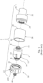
- Cartomizer 2 consists of a cylindrical cartridge 4 within which a cylindrical wick and coil arrangement (not shown) is centrally disposed and defines a hollow cylindrical interior which is open at first and second ends 6, 8.
- the cylindrical cartridge 4 is provided with a plurality of axial slots, two of which are referenced at 10, 12 and it is by means of such slots that exterior surfaces of the absorbent wick are exposed to the liquid nicotine-containing formulation which the cartomizer is adapted to receive prior to use.
- Screw threaded portions 14, 16 are provided at either end of the cartridge which facilitate secure connections to, on the one hand, an air flow regulator component 20 and on the other hand a mouthpiece and liquid charging assembly 22.
- Air flow regulator 20 and mouthpiece assembly are provided with corresponding threaded portions, and a plurality of rubber or other suitable material O-ring seals are provided (not shown) as required to ensure that the connection between screw-threaded connection between these parts is essentially sealed and fluid- impregnable.
- the cartomizer assembly further includes a clear plastics material cylindrical out sleeve 30 which, during assembly, is clamped between air flow regulator 20 and mouthpiece assembly 22, and again, appropriately sized and positioned O-ring seals (not shown) are provided to ensure that reliable fluid impregnable seals are created between both annular ends 32, 34 of the sleeve and the air flow regulator 20 and the mouthpiece assembly 22 respectively.
- two separate, sealed chambers are defined within the cartomizer 2, the first consisting essentially of the cylindrical hollow interior of the cylindrical cartridge 4, and the second being the generally annular cavity defined between said cartridge and the interior surface of the cylindrical sleeve 30 and it is into this annular cavity that the nicotine-containing liquid is deposited prior to use through the mouthpiece and charging assembly 30 through an appropriate charging slot (not shown) provided in assembly 22.
- the wick and coil arrangement itself is also essentially cylindrical and comprises an annular layer of an absorbent material such as cotton or some organic or inorganic synthetic equivalent material which forms the wick, and a simple electrical coil is disposed directly adjacent the interior cylindrical surface of the wick layer with the various windings thereof extending axially from one end of the wick layer to the other.
- a plurality of slots 10, 12 are provided so that portions of the wick layer are exposed thereby, and liquid contained within the annular cavity surrounding the wick and coil arrangement is in direct contact with said exposed wick layer portions which thus absorb and become soaked with the said liquid beneath the level of said liquid.
- the wicking nature of the absorbent material wick encourages the flow of liquid within the wick from the soaked regions to other regions not ordinarily submerged in liquid, and while the distribution of liquid throughout the wick is far from uniform, in general the wicking effect is sufficient to ensure that the majority of the wick is at least moist if not entirely soaked with the aerosolizable nicotine-containing liquid formulation.
- the coil of the wick and coil assembly must of course be electrically connected to the battery, and such electrical connection is most commonly achieved by means of a simple two-pole screw thread connection indicated generally at 40 provided on a distal closed end of the air flow regulator.
- the screw thread connection may comprise firstly an exterior screw thread by means of which an electrical connection is achieved to one pole of the battery, and secondly an interior spigot or pin by which electrical connection is achieved to the second pole of the battery.
- the various O-ring seals provided as part of the cartomizer assembly ensure that the annular liquid-containing cavity to the exterior of the wick and coil assembly is effectively isolated from its hollow interior in which the coil is disposed.
- One of the fundamental reasons behind such isolation relates to the required airflow which is to occur within the cartomizer assembly when the ENDS is active and heat from the coil is causing aerosolization of the absorbed liquid in the wick.
- the cartomizer assembly includes a mouthpiece component 26 consisting of a short hollow plastic tube or plug which is sealingly inserted into, or which forms an integral part of the mouthpiece assembly 22.
- the present invention adopts a very different approach and seeks to provide a different type of ENDS wherein an essentially disposable substrate component is pre-dosed with a relatively much smaller amount of a nicotine-containing formulation, and being equivalent to that which a smoker of a conventional tobacco product, in particular a cigarette, might be expected to consume during the smoking of a single such cigarette.
- the formulation will be a viscous liquid, a gel, or a solid which can be liquefied by application of heat, or indeed a material having the physical characteristic that it does not tend to flow over the surface of the substrate to any great extent, whether being aerosolised or not.
- base liquids e.g.
- glycerols polyethylene glycol (PEG), vegetable glycerol (VG), and/or propylene glycol (PG)) with liquid nicotine to manufacture a conventional e-liquid with the desired nicotine concentrations (e.g. 6-20 mg/ml)
- PEG polyethylene glycol
- VG vegetable glycerol
- PG propylene glycol
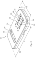
- cover 54 may be provided with a first lateral slot 56 and a pair of longitudinal slots 58, 60, all of which expose respective areas of a substrate 70 sandwiched within the substrate component and between said base and said cover, as more clearly seen in Figure 3 .
- lateral slot 56 is disposed towards a first (rear) end of the substrate component and exposes a corresponding area of the substrate 70.
- contact portions, one of which is referenced at 72, of an electrically resistive heating element 74 can be seen, such having been applied to an upper surface of the substrate 70, for example by screen-printing or otherwise.
- Contact portions 72 and resistive heating element will ideally be of the order of only 10s or 100s of microns thick.
- said contact portions will be exposed and accessible through the lateral slot 56, and an electrical connection therewith may be achieved through said lateral slot by means of a pair of appropriately sized electrical contacts or terminals (in general, the substrate will be provided with at least a pair of such contact portions 70, laterally spaced apart, and as may be required to complete an electrical circuit with the resistive heating element 74).
- base 52 is provided with an appropriately sized rebate 62 (which may be of course be alternatively or similarly provided on the underside of the cover 54) which can accept the substrate 70 and which may be resiliently or fixedly retained therein and thereby.
- longitudinally orientated slots 58, 60 provided in the cover such coincide with and thus selectively expose areas of the resistive heating element 74 such that a pair of globules 80 (see also Figure 3 ) of a suitable amount of a nicotine-containing formulation and having been previously applied to and/or deposited on the upper surface of said substrate in appropriate locations over said resistive heating element are substantially contained within the longitudinally orientated slots 58, 60 when the substrate component is assembled.
- the upper surface of internally and fixedly mounted substrate and said interior channels provided on the underside of the cover 96 together cooperate to define a pair of interior conduits within the substrate component whereby air drawn into apertures 100B, 102B is capable of flowing internally within the substrate component along said conduits before ultimately emerging therefrom through apertures 100A, 100B respectively, and as will hereinafter be more fully described.
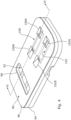
- the cover 54 may additionally provided with a pair of lateral inlet air flow channels 82, 84 by means of which secondary air flows into channels 58, 60 can be established (air flowing within the channels 58, 60 from front to rear being considered primary) as indicated at 82A, 84A respectively.
- the source of such air will, like that for the primary air flows, will generally be the same, i.e. ambient atmosphere, but the fact that there is some lateral component of velocity of such air will inevitably aid to the mixing of the primary and secondary air flows.
- any one or more of the channels 58, 60, 82, 84 may be provided with one or more baffle formations to further aid mixing of both primary and secondary fluid flows at any time occurring within said channels, and which may induce some degree of randomness or even turbulence of the flows occurring therein.
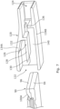
- baffle formations may be provided on the underside of the cover 96 in the channel formations 100, 102 provided therein, and additionally, one or more further lateral channel formations may be provided and cooperate with both the base 94 and the substrate 92 to define conduits having lateral entrances and by means of which it may be possible to establish secondary at least partially laterally directed airflows interiorly of the substrate component 90, said secondary airflows ultimately being delivered to and mixing with the primary air flows occurring at any time within the conduits defined between the substrate component and the said channels 100, 102.
- FIG. 6 there is shown a sectional perspective view of the substrate component 90 of Figure 4 and in which it can be more clearly seen how the substrate 92, base 94 and cover 96 cooperate with one another in the assembled substrate component, and in particular how an interior conduit is defined internally within the substrate component as a result of the cooperation of an upper surface of the substrate 92 and an underside of the cover 96 where the channel formations 100, and respective exit and entry openings or apertures 100A, 100B respectively thereof are provided.
- one or more fluid bypass apertures may be provided such that air being drawn into the mouthpiece component 120 through inlet 122 may not only mostly or partially be directed towards and into the conduit 100, but some portion of that air may be permitted to flow along a secondary pathway directly through said bypass aperture(s) through the mouthpiece component without necessarily flowing through the said conduit.
Landscapes
- Medicinal Preparation (AREA)
- Containers And Packaging Bodies Having A Special Means To Remove Contents (AREA)
- Nozzles (AREA)
Claims (16)
- Mundstückanordnung (50, 120) für eine Inhalationsvorrichtung (160), die Anordnung umfassend ein Mundstück (120) und eine Substratkomponente (50), wobei das Mundstück einen ersten Lufteinlass (122), der in der Nähe eines ersten Endes davon angeordnet ist, und einen Luftauslass (124), der in der Nähe eines zweiten Endes davon axial entfernt von dem ersten Ende angeordnet ist, aufweist, wobei der Einlass und der Auslass im Inneren des Mundstücks in Fluidverbindung miteinander sind, sodass der Fluidstrom innerhalb des Mundstücks dazu neigt, entlang einer im Wesentlichen längsgerichteten Achse aufzutreten, wobei das Mundstück einen Hohlraumbereich (140) aufweist, der in einem Inneren davon definiert ist und der angepasst ist, die Substratkomponente innerhalb des Mundstücks aufzunehmen und zu positionieren, sodass die Substratkomponente mit dem Flüssigkeitsstrom interagiert, wenn er auftritt, die Substratkomponente ferner umfassend mindestens eine Abdeckung (54), die mindestens eine im Wesentlichen ebene Fläche aufweist, in der mindestens ein länglicher Schlitz (58, 60) bereitgestellt ist, und ein ebenes Substrat (70), das fest unter der Abdeckung montiert ist und einen Bereich aufweist, auf den ein elektrisches Widerstandselement (74) aufgebracht wurde, wobei der längliche Schlitz zumindest teilweise mit dem Bereich übereinstimmt, um den Bereich freizulegen, dadurch gekennzeichnet, dass
die im Wesentlichen ebene Oberfläche der Abdeckung mit einer entsprechenden Innenfläche (128) des Hohlraumbereichs zusammenwirkt, sodass der mindestens eine längliche Schlitz, die entsprechende Innenfläche, und jener Teil des Substrats, der durch den mindestens einen länglichen Schlitz freiliegt, zusammen mindestens einen Kanal im Inneren des Substrats definieren, in und durch den mindestens ein Teil eines Fluidstroms, der innerhalb der Mundstückkomponente auftritt, notwendigerweise geleitet wird, sodass eine Menge einer aerosolierbaren Formulierung (80), die auf den Substratbereich aufgebracht wurde und als Ergebnis der Anwendung einer Erregungsenergie auf das Heizelement aerosolisiert wird, in dem Fluidstrom, der innerhalb des Kanals auftritt, mitgeführt wird. - Mundstückanordnung (50, 120) nach Anspruch 1, wobei ein beliebiger und die Gesamtheit eines Fluidstroms, der innerhalb des Mundstücks (120) auftritt, in und durch den mindestens einen Kanal geleitet wird, der im Inneren der Substratkomponente (50) definiert ist.
- Mundstückanordnung (50, 120) nach einem der vorherigen Ansprüche, wobei die Substratkomponente (50) länglich ist und der mindestens eine längliche Schlitz (58, 60) im Wesentlichen parallel zu der Längsachse der Substratkomponente ausgerichtet ist.
- Mundstückanordnung (50, 120) nach einem der vorherigen Ansprüche, wobei die Substratkomponente mit zwei länglichen Schlitzen (58, 60) versehen ist, die linear und parallel konfiguriert und ausgerichtet sind.
- Mundstückanordnung (50, 120) nach einem der Ansprüche 1, 3 oder 4, wobei das Mundstück innen mit mindestens einem sekundären Kanal (150) versehen ist, der als Fluid-Bypass wirkt, indem ein ursprünglich einheitlicher Fluidstrom, der durch den Einlass (122) davon in das Mundstücks eintritt, in mindestens zwei separate Teile aufgeteilt wird, einen ersten aktiven Teil, der gezwungen ist, in und durch den mindestens einen Kanal zu strömen, der im Inneren der Substratkomponente (50) definiert ist, und einen zweiten Bypass-Teil, der von dem ersten aktiven Teil getrennt und verschieden ist und von diesem für einen Großteil des Wegs innerhalb des Mundstücks getrennt ist.
- Mundstückanordnung (50, 120) nach Anspruch 5, wobei der erste aktive Teil und der sekundäre Bypass-Teil des ursprünglich einheitlichen Fluidstroms, der in das Mundstück eintritt, innerhalb des Mundstücks in einer speziellen Mischkammer (142) davon wiedervereinigt werden, die stromabwärts von der Substratkomponente (50), aber stromaufwärts von dem Mundstückauslass (124) ist.
- Mundstückanordnung (50, 120) nach einem der vorherigen Ansprüche, wobei das Mundstück (120) mit einer oder mehreren inneren Ablenkplattenformationen versehen ist.
- Mundstückanordnung (50, 120) nach einem der vorherigen Ansprüche, wobei eine oder mehrere Ablenkplattenformationen in dem mindestens einen Kanal bereitgestellt sind.
- Mundstückanordnung (50, 120) nach einem der vorherigen Ansprüche, wobei das Mundstück (120) mit mindestens einem weiteren Lufteinlass in Form von mindestens einer Öffnung versehen ist, die durch eines von Folgenden bereitgestellt und darin angeordnet ist: eine seitliche Wand, eine obere Wand und eine untere Wand des Mundstücks, wobei die mindestens eine Öffnung zwischen dem ersten Einlass (122) und dem Auslass (124) angeordnet ist und mit beiden in Fluidverbindung ist, wobei eine Innenfläche der seitlichen, oberen oder unteren Wand eine derjenigen Flächen ist, die den Fluidstrom im Inneren und in Längsrichtung des Mundstücks beschränkt, sodass die anfängliche Bewegungsrichtung von Luft, die in die Öffnung eintritt, im Wesentlichen senkrecht zu der Richtung eines Fluidstroms innerhalb des Mundstücks von dem Einlass zu dem Auslass ist.
- Mundstückanordnung (50, 120) nach Anspruch 9, wobei die Position der mindestens einen Öffnung eine von Folgenden ist: näher an dem Mundstückeinlass (122) als an seinem Auslass (124) und näher an dem Mundstückauslass als an seinem Einlass.
- Mundstückanordnung (50, 120) nach Anspruch 1 oder einem der Ansprüche 3-10, wobei die Substratkomponente (50) mit mindestens einer sekundären Kanalformation (82, 84) versehen ist, die einen Eingang aufweist, der von dem Eingang des mindestens einen länglichen Schlitzes (58, 60) getrennt ist, wobei die mindestens eine sekundäre Kanalformation eines von Folgenden ist:- vollständig getrennt von dem mindestens einen länglichen Schlitz, indem die mindestens eine sekundäre Kanalformation mit ihren eigenen separaten und getrennten Ausgängen versehen ist, und- vereinigt mit dem länglichen Schlitz, dahingehend, dass die mindestens eine sekundäre Kanalformation in einer oberen, unteren oder seitlichen Wand davon in den mindestens einen länglichen Schlitz einmündet, sodass es einen Zusammenfluss der Fluidströme zu einem beliebigen Zeitpunkt innerhalb des mindestens einen länglichen Schlitzes und der mindestens einen sekundären Kanalformation gibt.
- Mundstückanordnung (50, 120) nach Anspruch 11, wobei der mindestens eine längliche Schlitz (58, 60) und die mindestens eine sekundäre Kanalformation (82, 84) miteinander verbunden sind und der Zusammenfluss der Fluidströme, die zu einem beliebigen Zeitpunkt innerhalb des mindestens einen länglichen Schlitzes und der mindestens einen sekundären Kanalformation auftreten, an einer axialen Position der Substratkomponente (50) erfolgt, die eines von Folgenden ist: stromaufwärts von dem Substratbereich, im Wesentlichen deckungsgleich mit diesem Substratbereich und stromabwärts von diesem Bereich.
- Mundstückanordnung (50, 120) nach Anspruch 9 und Anspruch 11, wobei ein Eingang der mindestens einen sekundären Kanalformation der Substratkomponente mit der mindestens einen weiteren Fluideinlassöffnung zusammenfällt, die in dem Mundstück (120) bereitgestellt ist.
- Mundstückanordnung (50, 120) nach Anspruch 13, wobei die mindestens eine sekundäre Kanalformation (82, 84), die in der Substratkomponente (50) bereitgestellt ist, insofern lateral ist, als der Eingang der sekundären Kanalformation in einer seitlichen, oberen oder unteren Wand der Substratkomponente bereitgestellt ist, sodass zumindest anfangs die Richtung des Fluids, das in die mindestens eine sekundäre Kanalformation strömt, im Wesentlichen senkrecht zu der Richtung des Fluidstroms in dem mindestens einen Kanal ist, der teilweise durch den mindestens einen länglichen Schlitz (58, 60) definiert ist, wenn solche Fluidströme auftreten.
- Mundstückanordnung (50, 120) nach einem der vorherigen Ansprüche, wobei der Hohlraumbereich (140) zumindest teilweise durch mindestens eine Formation (126, 128, 132) in Form eines Auslegers definiert ist, der im Inneren des Mundstücks bereitgestellt ist, der leicht in den Hohlraumbereich vorgespannt ist, wenn keine Substratkomponente darin vorhanden ist, sodass, wenn eine Substratkomponente in den Hohlraumbereich eingeführt wird, sie als Resultat der Wirkung des Auslegers darin elastisch gehalten wird.
- Mundstückanordnung (50, 120) nach Anspruch 15, wobei das vordere freie Ende (130) der freitragenden Formation (128, 132) mit einer geeignet ausgerichteten abgeschrägten Oberfläche versehen ist, um ein Einführen einer Substratkomponente (50) in den Hohlraumbereich innerhalb des Mundstücks zu erleichtern.
Priority Applications (1)
| Application Number | Priority Date | Filing Date | Title |
|---|---|---|---|
| EP23218162.8A EP4335317A3 (de) | 2018-01-11 | 2019-01-10 | Mundstückanordnung für eine inhalationsvorrichtung mit einer austauschbaren substratkomponente und austauschbare substratkomponente dafür |
Applications Claiming Priority (2)
| Application Number | Priority Date | Filing Date | Title |
|---|---|---|---|
| GBGB1800500.9A GB201800500D0 (en) | 2018-01-11 | 2018-01-11 | A mouthpiece assmebly for an inhalation device including a replaceable substrate component,and a replaceable substrate component therefor |
| PCT/EP2019/050515 WO2019137982A1 (en) | 2018-01-11 | 2019-01-10 | A mouthpiece assembly for an inhalation device including a replaceable substrate component, and a replaceable substrate component therefor |
Related Child Applications (2)
| Application Number | Title | Priority Date | Filing Date |
|---|---|---|---|
| EP23218162.8A Division EP4335317A3 (de) | 2018-01-11 | 2019-01-10 | Mundstückanordnung für eine inhalationsvorrichtung mit einer austauschbaren substratkomponente und austauschbare substratkomponente dafür |
| EP23218162.8A Division-Into EP4335317A3 (de) | 2018-01-11 | 2019-01-10 | Mundstückanordnung für eine inhalationsvorrichtung mit einer austauschbaren substratkomponente und austauschbare substratkomponente dafür |
Publications (3)
| Publication Number | Publication Date |
|---|---|
| EP3737248A1 EP3737248A1 (de) | 2020-11-18 |
| EP3737248C0 EP3737248C0 (de) | 2024-07-17 |
| EP3737248B1 true EP3737248B1 (de) | 2024-07-17 |
Family
ID=61256253
Family Applications (2)
| Application Number | Title | Priority Date | Filing Date |
|---|---|---|---|
| EP23218162.8A Pending EP4335317A3 (de) | 2018-01-11 | 2019-01-10 | Mundstückanordnung für eine inhalationsvorrichtung mit einer austauschbaren substratkomponente und austauschbare substratkomponente dafür |
| EP19700659.6A Active EP3737248B1 (de) | 2018-01-11 | 2019-01-10 | Mundstückanordnung für eine inhalationsvorrichtung mit einer austauschbaren substratkomponente und austauschbare substratkomponente dafür |
Family Applications Before (1)
| Application Number | Title | Priority Date | Filing Date |
|---|---|---|---|
| EP23218162.8A Pending EP4335317A3 (de) | 2018-01-11 | 2019-01-10 | Mundstückanordnung für eine inhalationsvorrichtung mit einer austauschbaren substratkomponente und austauschbare substratkomponente dafür |
Country Status (9)
| Country | Link |
|---|---|
| US (2) | US12329205B2 (de) |
| EP (2) | EP4335317A3 (de) |
| JP (1) | JP7273061B2 (de) |
| KR (1) | KR102722576B1 (de) |
| CN (1) | CN111787820B (de) |
| AU (1) | AU2019207744B2 (de) |
| CA (1) | CA3088045A1 (de) |
| GB (1) | GB201800500D0 (de) |
| WO (1) | WO2019137982A1 (de) |
Families Citing this family (4)
| Publication number | Priority date | Publication date | Assignee | Title |
|---|---|---|---|---|
| WO2018167166A1 (en) * | 2017-03-16 | 2018-09-20 | Project Paradise Limited | A mouthpiece and heater assembly for an inhalation device |
| CN208510076U (zh) * | 2018-05-29 | 2019-02-19 | 深圳麦克韦尔股份有限公司 | 电子烟 |
| GB202100353D0 (en) | 2021-01-12 | 2021-02-24 | Ventus Medical Ltd | Aerosolizable nicoltine-containing formulations |
| GB202111258D0 (en) * | 2021-08-04 | 2021-09-15 | Nicoventures Trading Ltd | A consumable for use with an aerosol provision device |
Family Cites Families (30)
| Publication number | Priority date | Publication date | Assignee | Title |
|---|---|---|---|---|
| CA1001193A (en) * | 1973-02-28 | 1976-12-07 | S.R.C. Laboratories | Variable flow nozzle |
| JPS5164556U (de) * | 1974-11-16 | 1976-05-21 | ||
| CN1812843A (zh) * | 2003-07-04 | 2006-08-02 | 英克罗有限公司 | 喷嘴结构 |
| EP1709980A1 (de) * | 2005-04-05 | 2006-10-11 | Reckitt Benckiser (UK) LIMITED | Verdampfer |
| US7726320B2 (en) * | 2006-10-18 | 2010-06-01 | R. J. Reynolds Tobacco Company | Tobacco-containing smoking article |
| US8881737B2 (en) * | 2012-09-04 | 2014-11-11 | R.J. Reynolds Tobacco Company | Electronic smoking article comprising one or more microheaters |
| DE202014011261U1 (de) * | 2013-12-23 | 2018-11-13 | Juul Labs Uk Holdco Limited | Systeme für eine Verdampfungsvorrichtung |
| US20150257447A1 (en) * | 2014-03-11 | 2015-09-17 | Voodoo Science Llc | Electronic Cigarette Assembly |
| EP3166430B2 (de) * | 2014-07-11 | 2025-03-26 | Philip Morris Products S.A. | Aerosolbildungskartusche mit einem tabakhaltigen material |
| KR20240171169A (ko) * | 2014-07-11 | 2024-12-06 | 필립모리스 프로덕츠 에스.에이. | 보호 포일을 구비한 에어로졸 형성 카트리지 |
| CN106535681B (zh) * | 2014-07-11 | 2020-01-17 | 菲利普莫里斯生产公司 | 包括液体尼古丁源的气溶胶形成筒 |
| RU2685331C2 (ru) | 2014-07-11 | 2019-04-17 | Филип Моррис Продактс С.А. | Система, генерирующая аэрозоль, с улучшенным управлением потоком воздуха |
| CN105830369B (zh) | 2014-07-29 | 2018-09-21 | 华为技术有限公司 | 以太网无源光网络系统中设备注册和波长切换的方法和装置 |
| KR102601370B1 (ko) * | 2015-03-27 | 2023-11-13 | 필립모리스 프로덕츠 에스.에이. | 재밀봉 가능한 에어로졸 발생 물품 |
| KR20250099417A (ko) | 2015-07-09 | 2025-07-01 | 필립모리스 프로덕츠 에스.에이. | 에어로졸 발생 시스템용 히터 조립체 |
| CA2987161A1 (en) | 2015-08-21 | 2017-03-02 | Philip Morris Products, S.A. | A cartridge assembly for an aerosol-generating system and an aerosol-generating system comprising a cartridge assembly |
| US10500354B2 (en) * | 2015-09-25 | 2019-12-10 | Sanmina Corporation | System and method for atomizing and monitoring a drug cartridge during inhalation treatments |
| US11632978B2 (en) * | 2015-10-22 | 2023-04-25 | Philip Morris Products S.A. | Aerosol-generating article and method for manufacturing such aerosol-generating article; aerosol-generating device and system |
| US12042809B2 (en) * | 2015-11-02 | 2024-07-23 | Altria Client Services Llc | Aerosol-generating system comprising a vibratable element |
| KR102658425B1 (ko) * | 2016-01-11 | 2024-04-17 | 사이키 메디컬 엘티디. | 개인용 기화 장치 |
| GB2550540B (en) * | 2016-03-24 | 2021-09-29 | Nicoventures Trading Ltd | Vapour provision device |
| CN105861559B (zh) | 2016-04-11 | 2018-05-01 | 苏州奥特铭医药科技有限公司 | 一种能直接反应i型干扰素应答的慢病毒载体及其制备方法与应用 |
| US10772355B2 (en) * | 2016-07-29 | 2020-09-15 | Altria Client Services Llc | Aerosol-generating system including a heated gel container |
| CN120549284A (zh) * | 2016-07-29 | 2025-08-29 | 菲利普莫里斯生产公司 | 包括加热的凝胶容器的气溶胶生成系统 |
| CN106510001A (zh) * | 2016-12-20 | 2017-03-22 | 惠州市吉瑞科技有限公司深圳分公司 | 一种雾化器 |
| EP3585192A1 (de) * | 2017-03-29 | 2020-01-01 | JT International S.A. | Vorrichtung, system und verfahren zur erzeugung eines aerosols |
| CN206629997U (zh) * | 2017-04-11 | 2017-11-14 | 研能科技股份有限公司 | 电子香烟 |
| GB2561867B (en) * | 2017-04-25 | 2021-04-07 | Nerudia Ltd | Aerosol delivery system |
| ES2893115T3 (es) * | 2017-07-14 | 2022-02-08 | Philip Morris Products Sa | Un sistema generador de aerosol con flujo de aire de ventilación oculto |
| US11019850B2 (en) * | 2018-02-26 | 2021-06-01 | Rai Strategic Holdings, Inc. | Heat conducting substrate for electrically heated aerosol delivery device |
-
2018
- 2018-01-11 GB GBGB1800500.9A patent/GB201800500D0/en not_active Ceased
-
2019
- 2019-01-10 AU AU2019207744A patent/AU2019207744B2/en active Active
- 2019-01-10 CA CA3088045A patent/CA3088045A1/en active Pending
- 2019-01-10 EP EP23218162.8A patent/EP4335317A3/de active Pending
- 2019-01-10 KR KR1020207023200A patent/KR102722576B1/ko active Active
- 2019-01-10 JP JP2020559018A patent/JP7273061B2/ja active Active
- 2019-01-10 EP EP19700659.6A patent/EP3737248B1/de active Active
- 2019-01-10 US US16/961,040 patent/US12329205B2/en active Active
- 2019-01-10 WO PCT/EP2019/050515 patent/WO2019137982A1/en not_active Ceased
- 2019-01-10 CN CN201980015434.XA patent/CN111787820B/zh active Active
-
2024
- 2024-01-03 US US18/403,311 patent/US12599177B2/en active Active
Also Published As
| Publication number | Publication date |
|---|---|
| WO2019137982A1 (en) | 2019-07-18 |
| EP3737248A1 (de) | 2020-11-18 |
| US20240148067A1 (en) | 2024-05-09 |
| CN111787820B (zh) | 2024-03-22 |
| EP4335317A2 (de) | 2024-03-13 |
| US20200352242A1 (en) | 2020-11-12 |
| KR102722576B1 (ko) | 2024-10-25 |
| EP4335317A3 (de) | 2024-06-19 |
| AU2019207744A1 (en) | 2020-08-06 |
| JP2021510542A (ja) | 2021-04-30 |
| JP7273061B2 (ja) | 2023-05-12 |
| EP3737248C0 (de) | 2024-07-17 |
| US12599177B2 (en) | 2026-04-14 |
| CN111787820A (zh) | 2020-10-16 |
| KR20200118053A (ko) | 2020-10-14 |
| GB201800500D0 (en) | 2018-02-28 |
| US12329205B2 (en) | 2025-06-17 |
| CA3088045A1 (en) | 2019-07-18 |
| AU2019207744B2 (en) | 2024-06-27 |
Similar Documents
| Publication | Publication Date | Title |
|---|---|---|
| US12599177B2 (en) | Mouthpiece assembly for an inhalation device including a replaceable substrate component, and a replaceable substrate component therefor | |
| US11511057B2 (en) | Aerosol delivery system | |
| KR101969566B1 (ko) | 전자 담배 흡입기능이 구비된 전기 가열형 담배 흡입장치 | |
| CN110367592B (zh) | 电子吸烟器具的液体气溶胶制剂 | |
| US20180199618A1 (en) | Vaporizable Tobacco Wax Compositions and Container thereof | |
| EP3503749B1 (de) | Vorrichtung und system | |
| IL269098B (en) | A mouthpiece and heater assembly for an inhalation device | |
| WO2018064032A1 (en) | Vaporizable tobacco wax compositions and container thereof | |
| KR20160012109A (ko) | 전자 담배 | |
| GB2547699A (en) | System, apparatus and method | |
| KR20050037919A (ko) | 액체 증기 흡입 기구 | |
| RU111765U1 (ru) | Персональный ингалятор | |
| WO2019178448A1 (en) | Vaporizable tobacco wax compositions and container thereof | |
| KR102354450B1 (ko) | 에어로졸 생성 장치 | |
| WO2020187937A1 (en) | Aerosol delivery system | |
| WO2019068780A2 (en) | EXCITATION DEVICE FOR ELECTRONIC INHALER, METHOD FOR ELECTRONICALLY CONTROLLING DEVICE FOR EXCITATION OF ELECTRONIC INHALER, AND ELECTRONIC CONTROL CIRCUIT THEREFOR | |
| HK1252079A1 (en) | Device and system | |
| EP3711598A1 (de) | Aerosolabgabesystem | |
| EP3711608A1 (de) | Aerosolabgabesystem |
Legal Events
| Date | Code | Title | Description |
|---|---|---|---|
| STAA | Information on the status of an ep patent application or granted ep patent |
Free format text: STATUS: UNKNOWN |
|
| STAA | Information on the status of an ep patent application or granted ep patent |
Free format text: STATUS: THE INTERNATIONAL PUBLICATION HAS BEEN MADE |
|
| PUAI | Public reference made under article 153(3) epc to a published international application that has entered the european phase |
Free format text: ORIGINAL CODE: 0009012 |
|
| STAA | Information on the status of an ep patent application or granted ep patent |
Free format text: STATUS: REQUEST FOR EXAMINATION WAS MADE |
|
| 17P | Request for examination filed |
Effective date: 20200708 |
|
| AK | Designated contracting states |
Kind code of ref document: A1 Designated state(s): AL AT BE BG CH CY CZ DE DK EE ES FI FR GB GR HR HU IE IS IT LI LT LU LV MC MK MT NL NO PL PT RO RS SE SI SK SM TR |
|
| AX | Request for extension of the european patent |
Extension state: BA ME |
|
| DAV | Request for validation of the european patent (deleted) | ||
| DAX | Request for extension of the european patent (deleted) | ||
| STAA | Information on the status of an ep patent application or granted ep patent |
Free format text: STATUS: EXAMINATION IS IN PROGRESS |
|
| 17Q | First examination report despatched |
Effective date: 20230728 |
|
| REG | Reference to a national code |
Ref country code: DE Ref legal event code: R079 Free format text: PREVIOUS MAIN CLASS: A24F0047000000 Ipc: A24F0040485000 Ref document number: 602019055300 Country of ref document: DE |
|
| GRAP | Despatch of communication of intention to grant a patent |
Free format text: ORIGINAL CODE: EPIDOSNIGR1 |
|
| STAA | Information on the status of an ep patent application or granted ep patent |
Free format text: STATUS: GRANT OF PATENT IS INTENDED |
|
| RIC1 | Information provided on ipc code assigned before grant |
Ipc: A24F 40/485 20200101AFI20240202BHEP |
|
| INTG | Intention to grant announced |
Effective date: 20240219 |
|
| GRAS | Grant fee paid |
Free format text: ORIGINAL CODE: EPIDOSNIGR3 |
|
| GRAA | (expected) grant |
Free format text: ORIGINAL CODE: 0009210 |
|
| STAA | Information on the status of an ep patent application or granted ep patent |
Free format text: STATUS: THE PATENT HAS BEEN GRANTED |
|
| AK | Designated contracting states |
Kind code of ref document: B1 Designated state(s): AL AT BE BG CH CY CZ DE DK EE ES FI FR GB GR HR HU IE IS IT LI LT LU LV MC MK MT NL NO PL PT RO RS SE SI SK SM TR |
|
| REG | Reference to a national code |
Ref country code: CH Ref legal event code: EP |
|
| REG | Reference to a national code |
Ref country code: DE Ref legal event code: R096 Ref document number: 602019055300 Country of ref document: DE |
|
| REG | Reference to a national code |
Ref country code: IE Ref legal event code: FG4D |
|
| U01 | Request for unitary effect filed |
Effective date: 20240726 |
|
| U07 | Unitary effect registered |
Designated state(s): AT BE BG DE DK EE FI FR IT LT LU LV MT NL PT SE SI Effective date: 20240809 |
|
| PG25 | Lapsed in a contracting state [announced via postgrant information from national office to epo] |
Ref country code: NO Free format text: LAPSE BECAUSE OF FAILURE TO SUBMIT A TRANSLATION OF THE DESCRIPTION OR TO PAY THE FEE WITHIN THE PRESCRIBED TIME-LIMIT Effective date: 20241017 |
|
| PG25 | Lapsed in a contracting state [announced via postgrant information from national office to epo] |
Ref country code: GR Free format text: LAPSE BECAUSE OF FAILURE TO SUBMIT A TRANSLATION OF THE DESCRIPTION OR TO PAY THE FEE WITHIN THE PRESCRIBED TIME-LIMIT Effective date: 20241018 Ref country code: PL Free format text: LAPSE BECAUSE OF FAILURE TO SUBMIT A TRANSLATION OF THE DESCRIPTION OR TO PAY THE FEE WITHIN THE PRESCRIBED TIME-LIMIT Effective date: 20240717 |
|
| PG25 | Lapsed in a contracting state [announced via postgrant information from national office to epo] |
Ref country code: IS Free format text: LAPSE BECAUSE OF FAILURE TO SUBMIT A TRANSLATION OF THE DESCRIPTION OR TO PAY THE FEE WITHIN THE PRESCRIBED TIME-LIMIT Effective date: 20241117 |
|
| PG25 | Lapsed in a contracting state [announced via postgrant information from national office to epo] |
Ref country code: HR Free format text: LAPSE BECAUSE OF FAILURE TO SUBMIT A TRANSLATION OF THE DESCRIPTION OR TO PAY THE FEE WITHIN THE PRESCRIBED TIME-LIMIT Effective date: 20240717 |
|
| PG25 | Lapsed in a contracting state [announced via postgrant information from national office to epo] |
Ref country code: RS Free format text: LAPSE BECAUSE OF FAILURE TO SUBMIT A TRANSLATION OF THE DESCRIPTION OR TO PAY THE FEE WITHIN THE PRESCRIBED TIME-LIMIT Effective date: 20241017 Ref country code: ES Free format text: LAPSE BECAUSE OF FAILURE TO SUBMIT A TRANSLATION OF THE DESCRIPTION OR TO PAY THE FEE WITHIN THE PRESCRIBED TIME-LIMIT Effective date: 20240717 |
|
| PG25 | Lapsed in a contracting state [announced via postgrant information from national office to epo] |
Ref country code: RS Free format text: LAPSE BECAUSE OF FAILURE TO SUBMIT A TRANSLATION OF THE DESCRIPTION OR TO PAY THE FEE WITHIN THE PRESCRIBED TIME-LIMIT Effective date: 20241017 Ref country code: PL Free format text: LAPSE BECAUSE OF FAILURE TO SUBMIT A TRANSLATION OF THE DESCRIPTION OR TO PAY THE FEE WITHIN THE PRESCRIBED TIME-LIMIT Effective date: 20240717 Ref country code: NO Free format text: LAPSE BECAUSE OF FAILURE TO SUBMIT A TRANSLATION OF THE DESCRIPTION OR TO PAY THE FEE WITHIN THE PRESCRIBED TIME-LIMIT Effective date: 20241017 Ref country code: IS Free format text: LAPSE BECAUSE OF FAILURE TO SUBMIT A TRANSLATION OF THE DESCRIPTION OR TO PAY THE FEE WITHIN THE PRESCRIBED TIME-LIMIT Effective date: 20241117 Ref country code: HR Free format text: LAPSE BECAUSE OF FAILURE TO SUBMIT A TRANSLATION OF THE DESCRIPTION OR TO PAY THE FEE WITHIN THE PRESCRIBED TIME-LIMIT Effective date: 20240717 Ref country code: GR Free format text: LAPSE BECAUSE OF FAILURE TO SUBMIT A TRANSLATION OF THE DESCRIPTION OR TO PAY THE FEE WITHIN THE PRESCRIBED TIME-LIMIT Effective date: 20241018 Ref country code: ES Free format text: LAPSE BECAUSE OF FAILURE TO SUBMIT A TRANSLATION OF THE DESCRIPTION OR TO PAY THE FEE WITHIN THE PRESCRIBED TIME-LIMIT Effective date: 20240717 |
|
| U20 | Renewal fee for the european patent with unitary effect paid |
Year of fee payment: 7 Effective date: 20250106 |
|
| PG25 | Lapsed in a contracting state [announced via postgrant information from national office to epo] |
Ref country code: SM Free format text: LAPSE BECAUSE OF FAILURE TO SUBMIT A TRANSLATION OF THE DESCRIPTION OR TO PAY THE FEE WITHIN THE PRESCRIBED TIME-LIMIT Effective date: 20240717 |
|
| PG25 | Lapsed in a contracting state [announced via postgrant information from national office to epo] |
Ref country code: CZ Free format text: LAPSE BECAUSE OF FAILURE TO SUBMIT A TRANSLATION OF THE DESCRIPTION OR TO PAY THE FEE WITHIN THE PRESCRIBED TIME-LIMIT Effective date: 20240717 |
|
| PG25 | Lapsed in a contracting state [announced via postgrant information from national office to epo] |
Ref country code: SK Free format text: LAPSE BECAUSE OF FAILURE TO SUBMIT A TRANSLATION OF THE DESCRIPTION OR TO PAY THE FEE WITHIN THE PRESCRIBED TIME-LIMIT Effective date: 20240717 |
|
| PLBE | No opposition filed within time limit |
Free format text: ORIGINAL CODE: 0009261 |
|
| STAA | Information on the status of an ep patent application or granted ep patent |
Free format text: STATUS: NO OPPOSITION FILED WITHIN TIME LIMIT |
|
| 26N | No opposition filed |
Effective date: 20250422 |
|
| REG | Reference to a national code |
Ref country code: CH Ref legal event code: PL |
|
| PG25 | Lapsed in a contracting state [announced via postgrant information from national office to epo] |
Ref country code: MC Free format text: LAPSE BECAUSE OF FAILURE TO SUBMIT A TRANSLATION OF THE DESCRIPTION OR TO PAY THE FEE WITHIN THE PRESCRIBED TIME-LIMIT Effective date: 20240717 |
|
| PG25 | Lapsed in a contracting state [announced via postgrant information from national office to epo] |
Ref country code: CH Free format text: LAPSE BECAUSE OF NON-PAYMENT OF DUE FEES Effective date: 20250131 |
|
| U20 | Renewal fee for the european patent with unitary effect paid |
Year of fee payment: 8 Effective date: 20260105 |
|
| PGFP | Annual fee paid to national office [announced via postgrant information from national office to epo] |
Ref country code: GB Payment date: 20260105 Year of fee payment: 8 |
|
| PGFP | Annual fee paid to national office [announced via postgrant information from national office to epo] |
Ref country code: IE Payment date: 20260105 Year of fee payment: 8 |
|
| PG25 | Lapsed in a contracting state [announced via postgrant information from national office to epo] |
Ref country code: RO Free format text: LAPSE BECAUSE OF FAILURE TO SUBMIT A TRANSLATION OF THE DESCRIPTION OR TO PAY THE FEE WITHIN THE PRESCRIBED TIME-LIMIT Effective date: 20240717 |