EP3736829A1 - Solid electrolyte material and battery - Google Patents
Solid electrolyte material and battery Download PDFInfo
- Publication number
- EP3736829A1 EP3736829A1 EP18898663.2A EP18898663A EP3736829A1 EP 3736829 A1 EP3736829 A1 EP 3736829A1 EP 18898663 A EP18898663 A EP 18898663A EP 3736829 A1 EP3736829 A1 EP 3736829A1
- Authority
- EP
- European Patent Office
- Prior art keywords
- solid electrolyte
- electrolyte material
- battery
- positive electrode
- negative electrode
- Prior art date
- Legal status (The legal status is an assumption and is not a legal conclusion. Google has not performed a legal analysis and makes no representation as to the accuracy of the status listed.)
- Withdrawn
Links
Images

Classifications
-
- C—CHEMISTRY; METALLURGY
- C01—INORGANIC CHEMISTRY
- C01F—COMPOUNDS OF THE METALS BERYLLIUM, MAGNESIUM, ALUMINIUM, CALCIUM, STRONTIUM, BARIUM, RADIUM, THORIUM, OR OF THE RARE-EARTH METALS
- C01F17/00—Compounds of rare earth metals
- C01F17/30—Compounds containing rare earth metals and at least one element other than a rare earth metal, oxygen or hydrogen, e.g. La4S3Br6
- C01F17/36—Compounds containing rare earth metals and at least one element other than a rare earth metal, oxygen or hydrogen, e.g. La4S3Br6 halogen being the only anion, e.g. NaYF4
-
- C—CHEMISTRY; METALLURGY
- C01—INORGANIC CHEMISTRY
- C01G—COMPOUNDS CONTAINING METALS NOT COVERED BY SUBCLASSES C01D OR C01F
- C01G15/00—Compounds of gallium, indium or thallium
- C01G15/006—Compounds containing gallium, indium or thallium, with or without oxygen or hydrogen, and containing two or more other elements
-
- C—CHEMISTRY; METALLURGY
- C01—INORGANIC CHEMISTRY
- C01G—COMPOUNDS CONTAINING METALS NOT COVERED BY SUBCLASSES C01D OR C01F
- C01G29/00—Compounds of bismuth
- C01G29/006—Compounds containing bismuth, with or without oxygen or hydrogen, and containing two or more other elements
-
- H—ELECTRICITY
- H01—ELECTRIC ELEMENTS
- H01B—CABLES; CONDUCTORS; INSULATORS; SELECTION OF MATERIALS FOR THEIR CONDUCTIVE, INSULATING OR DIELECTRIC PROPERTIES
- H01B1/00—Conductors or conductive bodies characterised by the conductive materials; Selection of materials as conductors
- H01B1/06—Conductors or conductive bodies characterised by the conductive materials; Selection of materials as conductors mainly consisting of other non-metallic substances
-
- H—ELECTRICITY
- H01—ELECTRIC ELEMENTS
- H01M—PROCESSES OR MEANS, e.g. BATTERIES, FOR THE DIRECT CONVERSION OF CHEMICAL ENERGY INTO ELECTRICAL ENERGY
- H01M10/00—Secondary cells; Manufacture thereof
- H01M10/05—Accumulators with non-aqueous electrolyte
- H01M10/052—Li-accumulators
-
- H—ELECTRICITY
- H01—ELECTRIC ELEMENTS
- H01M—PROCESSES OR MEANS, e.g. BATTERIES, FOR THE DIRECT CONVERSION OF CHEMICAL ENERGY INTO ELECTRICAL ENERGY
- H01M10/00—Secondary cells; Manufacture thereof
- H01M10/05—Accumulators with non-aqueous electrolyte
- H01M10/052—Li-accumulators
- H01M10/0525—Rocking-chair batteries, i.e. batteries with lithium insertion or intercalation in both electrodes; Lithium-ion batteries
-
- H—ELECTRICITY
- H01—ELECTRIC ELEMENTS
- H01M—PROCESSES OR MEANS, e.g. BATTERIES, FOR THE DIRECT CONVERSION OF CHEMICAL ENERGY INTO ELECTRICAL ENERGY
- H01M10/00—Secondary cells; Manufacture thereof
- H01M10/05—Accumulators with non-aqueous electrolyte
- H01M10/056—Accumulators with non-aqueous electrolyte characterised by the materials used as electrolytes, e.g. mixed inorganic/organic electrolytes
- H01M10/0561—Accumulators with non-aqueous electrolyte characterised by the materials used as electrolytes, e.g. mixed inorganic/organic electrolytes the electrolyte being constituted of inorganic materials only
- H01M10/0562—Solid materials
-
- H—ELECTRICITY
- H01—ELECTRIC ELEMENTS
- H01M—PROCESSES OR MEANS, e.g. BATTERIES, FOR THE DIRECT CONVERSION OF CHEMICAL ENERGY INTO ELECTRICAL ENERGY
- H01M4/00—Electrodes
- H01M4/02—Electrodes composed of, or comprising, active material
- H01M4/13—Electrodes for accumulators with non-aqueous electrolyte, e.g. for lithium-accumulators; Processes of manufacture thereof
-
- H—ELECTRICITY
- H01—ELECTRIC ELEMENTS
- H01M—PROCESSES OR MEANS, e.g. BATTERIES, FOR THE DIRECT CONVERSION OF CHEMICAL ENERGY INTO ELECTRICAL ENERGY
- H01M4/00—Electrodes
- H01M4/02—Electrodes composed of, or comprising, active material
- H01M4/62—Selection of inactive substances as ingredients for active masses, e.g. binders, fillers
-
- C—CHEMISTRY; METALLURGY
- C01—INORGANIC CHEMISTRY
- C01P—INDEXING SCHEME RELATING TO STRUCTURAL AND PHYSICAL ASPECTS OF SOLID INORGANIC COMPOUNDS
- C01P2004/00—Particle morphology
- C01P2004/60—Particles characterised by their size
- C01P2004/61—Micrometer sized, i.e. from 1-100 micrometer
-
- H—ELECTRICITY
- H01—ELECTRIC ELEMENTS
- H01M—PROCESSES OR MEANS, e.g. BATTERIES, FOR THE DIRECT CONVERSION OF CHEMICAL ENERGY INTO ELECTRICAL ENERGY
- H01M4/00—Electrodes
- H01M4/02—Electrodes composed of, or comprising, active material
- H01M2004/026—Electrodes composed of, or comprising, active material characterised by the polarity
- H01M2004/027—Negative electrodes
-
- H—ELECTRICITY
- H01—ELECTRIC ELEMENTS
- H01M—PROCESSES OR MEANS, e.g. BATTERIES, FOR THE DIRECT CONVERSION OF CHEMICAL ENERGY INTO ELECTRICAL ENERGY
- H01M4/00—Electrodes
- H01M4/02—Electrodes composed of, or comprising, active material
- H01M2004/026—Electrodes composed of, or comprising, active material characterised by the polarity
- H01M2004/028—Positive electrodes
-
- H—ELECTRICITY
- H01—ELECTRIC ELEMENTS
- H01M—PROCESSES OR MEANS, e.g. BATTERIES, FOR THE DIRECT CONVERSION OF CHEMICAL ENERGY INTO ELECTRICAL ENERGY
- H01M2300/00—Electrolytes
- H01M2300/0017—Non-aqueous electrolytes
- H01M2300/0065—Solid electrolytes
- H01M2300/0068—Solid electrolytes inorganic
-
- Y—GENERAL TAGGING OF NEW TECHNOLOGICAL DEVELOPMENTS; GENERAL TAGGING OF CROSS-SECTIONAL TECHNOLOGIES SPANNING OVER SEVERAL SECTIONS OF THE IPC; TECHNICAL SUBJECTS COVERED BY FORMER USPC CROSS-REFERENCE ART COLLECTIONS [XRACs] AND DIGESTS
- Y02—TECHNOLOGIES OR APPLICATIONS FOR MITIGATION OR ADAPTATION AGAINST CLIMATE CHANGE
- Y02E—REDUCTION OF GREENHOUSE GAS [GHG] EMISSIONS, RELATED TO ENERGY GENERATION, TRANSMISSION OR DISTRIBUTION
- Y02E60/00—Enabling technologies; Technologies with a potential or indirect contribution to GHG emissions mitigation
- Y02E60/10—Energy storage using batteries
Definitions
- the present disclosure relates to a solid electrolyte material and a battery.
- Patent Literature 1 discloses an all-solid battery using a sulfide solid electrolyte.
- Patent Literature 1 Japanese Patent Application Publication No. 2011-129312
- the solid electrolyte material in one aspect of the present disclosure is represented by a composition formula Li 3-3 ⁇ Y 1+ ⁇ -a M a Cl 6-x-y Br x I y , where M is at least one element selected from the group consisting of Al, Sc, Ga, and Bi;
- a solid electrolyte material having high lithium ion conductivity can be realized.
- the solid electrolyte material in the first embodiment is a solid electrolyte material represented by the following composition formula (1): Li 3-3 ⁇ Y 1+ ⁇ -a M a Cl 6-x-y Br x I y Formula (1) where M is one or more kinds of elements selected from the group consisting of Al, Sc, Ga, and Bi.
- a solid electrolyte material (halide solid electrolyte material) having high lithium ion conductivity can be realized.
- an all-solid secondary battery excellent in a charge / discharge characteristic can be realized by using the solid electrolyte material of the first embodiment.
- an all-solid secondary battery which does not including sulfur can be realized.
- the solid electrolyte material of the first embodiment does not have a configuration (for example, the configuration of Patent Literature 1) in which hydrogen sulfide is generated when exposed to the atmosphere. For this reason, an all-solid secondary battery which does not generate hydrogen sulfide and is excellent in safety can be realized.
- the solid electrolyte material in the first embodiment may satisfy 0.025 ⁇ a ⁇ 0.99 in the above composition formula (1).
- the solid electrolyte material in the first embodiment may satisfy 0.035 ⁇ a ⁇ 0.1 in the above composition formula (1).
- the solid electrolyte material in the first embodiment may satisfy -0.5 ⁇ ⁇ ⁇ 0.5 in the above composition formula (1).
- the solid electrolyte material in the first embodiment may satisfy -0.3 ⁇ ⁇ ⁇ 0.2 in the above composition formula (1).
- the solid electrolyte material in the first embodiment may be crystalline or amorphous.
- a shape of the solid electrolyte material in the first embodiment is not specifically limited, for example, an acicular shape, a spherical shape, or an elliptical spherical shape.
- the solid electrolyte material in the first embodiment may be particles. After a plurality of the particles are stacked, the plurality of the particles may be formed into a pellet shape or a plate shape by pressurization.
- the median diameter thereof may be not less than 0.1 ⁇ m and not more than 100 ⁇ m.
- the median diameter may be not less than 0.5 ⁇ m and not more than 10 ⁇ m.
- ion conductivity can be further improved.
- a better dispersion state of the solid electrolyte material and the active material in the first embodiment can be formed.
- the solid electrolyte material may be smaller than the median diameter of the active material.
- the solid electrolyte material in the first embodiment may be manufactured by the following method, for example.
- Binary halide raw material powders are prepared so as to provide a blending ratio of a target composition. For example, if Li 3 Y 0.95 Bi 0.05 Cl 6 is produced, LiCl, YCl 3 , and BiCl 3 are prepared at a molar ratio of approximately 3 : 0.95 : 0.05.
- the blending ratio may be adjusted in advance so as to cancel the change.
- the above-described values " ⁇ ", "a”, "x”, and “y” can be adjusted by adjusting the raw material, the blending ratio, and the synthesis process.
- the raw material powders are mixed well, the raw material powders are mixed and ground to react by a mechanochemical milling method. Subsequently, the powders may be sintered in a vacuum or an inert atmosphere.
- the raw material powders may be mixed well and then sintered in a vacuum or in an inert atmosphere.
- the powders are sintered within a range of 100 °C to 650 °C for 1 hour or longer.
- solid electrolyte material including the composition as described above is provided.
- the battery in the second embodiment is configured using the solid electrolyte material described in the first embodiment.
- the battery in the second embodiment comprises a solid electrolyte material, a positive electrode, a negative electrode, and an electrolyte layer.
- the electrolyte layer is a layer provided between the positive electrode and the negative electrode.
- At least one of the positive electrode, the electrolyte layer, and the negative electrode includes the solid electrolyte material in the first embodiment.
- the charge / discharge characteristic of the battery can be improved.
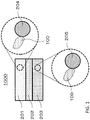
- FIG. 1 is a cross-sectional view showing a schematic configuration of a battery 1000 in the second embodiment.
- the battery 1000 in the second embodiment comprises a positive electrode 201, a negative electrode 203, and an electrolyte layer 202.
- the positive electrode 201 includes positive electrode active material particles 204 and solid electrolyte particles 100.
- the electrolyte layer 202 is disposed between the positive electrode 201 and the negative electrode 203.
- the electrolyte layer 202 includes an electrolyte material (for example, a solid electrolyte material).
- the negative electrode 203 includes negative electrode active material particles 205 and solid electrolyte particles 100.
- Each of the solid electrolyte particles 100 is a particle formed of the solid electrolyte material in the first embodiment or a particle including the solid electrolyte material in the first embodiment as a main component.
- the positive electrode 201 includes a material having a property of storing and releasing metal ions (for example, lithium ions).
- the positive electrode 201 includes, for example, a positive electrode active material (for example, the positive electrode active material particles 204).
- the positive electrode active material examples include lithium-containing transition metal oxides (e.g., Li(NiCoAl)O 2 or LiCoO 2 ), transition metal fluorides, polyanions, fluorinated polyanion materials, transition metal sulfides, transition metal oxyfluorides, transition metal oxysulfides, and transition metal oxynitrides.
- lithium-containing transition metal oxides e.g., Li(NiCoAl)O 2 or LiCoO 2
- transition metal fluorides e.g., Li(NiCoAl)O 2 or LiCoO 2
- polyanions e.g., Li(NiCoAl)O 2 or LiCoO 2
- fluorinated polyanion materials e.g., transition metal sulfides, transition metal oxyfluorides, transition metal oxysulfides, and transition metal oxynitrides.
- the median diameter of the positive electrode active material particles 204 may be not less than 0.1 ⁇ m and not more than 100 ⁇ m. If the median diameter of the positive electrode active material particles 204 is less than 0.1 ⁇ m, there is a possibility that the positive electrode active material particles 204 and the halide solid electrolyte material cannot form a good dispersion state in the positive electrode. As a result, the charge / discharge characteristic of the battery is lowered. In addition, if the median diameter of the positive electrode active material particles 204 is more than 100 ⁇ m, lithium diffusion in the positive electrode active material particles 204 is made slow. As a result, it may be difficult to operate the battery at a high output.
- the median diameter of the positive electrode active material particles 204 may be larger than the median diameter of the halide solid electrolyte material. Thereby, the good dispersion state of the positive electrode active material particles 204 and the halide solid electrolyte material can be formed.
- volume ratio "v : 100-v" between the positive electrode active material particles 204 and the halide solid electrolyte material included in the positive electrode 201 30 ⁇ v ⁇ 95 may be satisfied. If v ⁇ 30, it may be difficult to ensure an energy density of the battery sufficiently. In addition, if v > 95, it may be difficult to operate at high output.
- the thickness of the positive electrode 201 may be not less than 10 ⁇ m and not more than 500 ⁇ m. If the thickness of the positive electrode is less than 10 ⁇ m, it may be difficult to ensure an energy density of the battery sufficiently. In addition, if the thickness of the positive electrode is more than 500 ⁇ m, it may be difficult to operate at a high output.
- the electrolyte layer 202 is a layer including an electrolyte material.
- the electrolyte material is, for example, a solid electrolyte material.
- the electrolyte layer 202 may be a solid electrolyte layer.
- the solid electrolyte layer may include the solid electrolyte material in the first embodiment as a main component.
- the solid electrolyte layer may include the solid electrolyte material in the first embodiment, for example, at a weight ratio of not less than 50% (not less than 50% by weight) with respect to the entire solid electrolyte layer.
- the charge / discharge characteristic of the battery can be further improved.
- the solid electrolyte layer may include the solid electrolyte material in the first embodiment, for example, at a weight ratio of not less than 70% (not less than 70% by weight) with respect to the entire solid electrolyte layer.
- the charge / discharge characteristic of the battery can be further improved.
- the solid electrolyte layer which may include the solid electrolyte material in the first embodiment as a main component, may further include inevitable impurities.
- the solid electrolyte layer may include the starting materials used for the synthesis of the solid electrolyte material.
- the solid electrolyte layer may include by-products or decomposition products generated when the solid electrolyte material is synthesized.
- the solid electrolyte layer may include the solid electrolyte material in the first embodiment, for example, at a weight ratio of 100% (100% by weight) to the entire solid electrolyte layer, except for the inevitable impurities.
- the charge / discharge characteristic of the battery can be further improved.
- the solid electrolyte layer may be composed only of the solid electrolyte material in the first embodiment.
- the solid electrolyte layer may be composed only of a solid electrolyte material different from the solid electrolyte material in the first embodiment.
- a solid electrolyte material different from the solid electrolyte material in the first embodiment for example, Li 2 MgX 4 , Li 2 FeX 4 , Li(Al, Ga, In)X 4 , Li 3 (Al, Ga, In)X 6 , or LiI (X: CI, Br, I) may be used.
- the solid electrolyte layer may include simultaneously the solid electrolyte material in the first embodiment and the solid electrolyte material different from the solid electrolyte material in the first embodiment. At this time, both of them may be dispersed uniformly.
- the layer formed of the solid electrolyte material in the first embodiment and the layer formed of the solid electrolyte material different from the solid electrolyte material in the first embodiment may be sequentially arranged in the stacking direction of the battery.
- the thickness of the solid electrolyte layer may be not less than 1 ⁇ m and not more than 1,000 ⁇ m. If the thickness of the solid electrolyte layer is less than 1 ⁇ m, the possibility that the positive electrode 201 and the negative electrode 203 are shortcircuited increases. In addition, if the thickness of the solid electrolyte layer is more than 1,000 ⁇ m, it may be difficult to operate at a high output.
- the negative electrode 203 includes a material having a property of storing and releasing metal ions (for example, lithium ions).
- the negative electrode 203 includes, for example, a negative electrode active material (for example, the negative electrode active material particles 205).
- a metal material As the negative electrode active material, a metal material, a carbon material, an oxide, a nitride, a tin compound, or a silicon compound may be used.
- the metal material may be a single metal.
- the metal material may be an alloy.
- Examples of the metal material include a lithium metal and a lithium alloy.
- Examples of the carbon material include natural graphite, coke, graphitized carbon, carbon fiber, spherical carbon, artificial graphite, and amorphous carbon. From the viewpoint of capacity density, silicon (Si), tin (Sn), a silicon compound, or a tin compound may be preferably used. If a negative electrode active material having a low average reaction voltage is used, the effect of suppressing electrolysis by the solid electrolyte material in the first embodiment is better exhibited.
- the median diameter of the negative electrode active material particles 205 may be not less than 0.1 ⁇ m and not more than 100 ⁇ m. If the median diameter of the negative electrode active material particles 205 is less than 0.1 ⁇ m, there is a possibility that the negative electrode active material particles 205 and the solid electrolyte particles 100 cannot form a good dispersion state in the negative electrode. Thereby, the charge / discharge characteristic of a battery is lowered. On the other hand, if the median diameter of the negative electrode active material particles 205 is more than 100 ⁇ m, lithium diffusion in the negative electrode active material particles 205 is made slow. As a result, it may be difficult to operate the battery at a high output.
- the median diameter of the negative electrode active material particles 205 may be larger than the median diameter of the solid electrolyte particles 100. Thereby, the good dispersion state of the negative electrode active material particles 205 and the halide solid electrolyte material can be formed.
- volume ratio "v : 100-v" of the negative electrode active material particles 205 and the solid electrolyte particles 100 included in the negative electrode 203 30 ⁇ v ⁇ 95 may be satisfied. If v ⁇ 30, it may be difficult to ensure an energy density of the battery sufficiently. In addition, if v > 95, it may be difficult to operate at high output.
- the thickness of the negative electrode 203 may be not less than 10 ⁇ m and not more than 500 ⁇ m. If the thickness of the negative electrode is less than 10 ⁇ m, it may be difficult to ensure an energy density of the battery sufficiently. In addition, if the thickness of the negative electrode is more than 500 ⁇ m, it may be difficult to operate at a high output.
- At least one of the positive electrode 201, the electrolyte layer 202, and the negative electrode 203 may include a sulfide solid electrolyte or an oxide solid electrolyte for the purpose of improving ion conductivity, chemical stability, or electrochemical stability.
- a sulfide solid electrolyte Li 2 S-P 2 S 5 , Li 2 S-SiS 2 , Li 2 S-B 2 S 3 , Li 2 S-GeS 2 , Li 3.25 Ge 0.25 P 0.75 S 4 , or Li 10 GeP 2 S 12 may be used.
- a NASICON solid electrolyte such as LiTi 2 (PO 4 ) 3 and its element substitution products, a (LaLi)TiO 3 perovskite solid electrolyte, a LISICON solid electrolyte such as Li 14 ZnGe 4 O 16 , Li 4 SiO 4 , LiGeO 4 and its element substitution products, a garnet solid electrolyte such as Li 7 La 3 Zr 2 O 12 and its element substitution products, Li 3 N and its H substitution products, and Li 3 PO 4 and its N substitution products may be used.
- At least one of the positive electrode 201, the electrolyte layer 202, and the negative electrode 203 may include an organic polymer solid electrolyte for the purpose of increasing ion conductivity.
- an organic polymer solid electrolyte for example, a compound of a polymer compound and a lithium salt can be used.
- the polymer compound may have an ethylene oxide structure. Due to the ethylene oxide structure, a large amount of lithium salt can be included to further increase the ion conductivity.
- LiPF 6 , LiBF 4 , LiSbF 6 , LiAsF 6 , LiSO 3 CF 3 , LiN(SO 2 CF 3 ) 2 , LiN(SO 2 C 2 F 5 ) 2 , LiN(SO 2 CF 3 )(SO 2 C 4 F 9 ), or LiC(SO 2 CF 3 ) 3 may be used.
- the lithium salt one lithium salt selected from these may be used alone. Alternatively, a mixture of two or more kinds of the lithium salts selected from these may be used as the lithium salt.
- At least one of the positive electrode 201, the electrolyte layer 202, and the negative electrode 203 may include a non-aqueous electrolyte solution, a gel electrolyte, or an ionic liquid for the purpose of facilitating exchange of lithium ions and improving the output characteristic of the battery.
- the non-aqueous electrolyte solution includes a non-aqueous solvent and a lithium salt dissolved in the non-aqueous solvent.
- a non-aqueous solvent a cyclic carbonate solvent, a chain carbonate solvent, a cyclic ether solvent, a chain ether solvent, a cyclic ester solvent, a chain ester solvent, or a fluorine solvent may be used.
- the cyclic carbonate solvent include ethylene carbonate, propylene carbonate, and butylene carbonate.
- Examples of the chain carbonate solvent include dimethyl carbonate, ethyl methyl carbonate, and diethyl carbonate.
- Examples of the cyclic ether solvent include tetrahydrofuran, 1,4-dioxane, and 1,3-dioxolane.
- Examples of the chain ether solvent include 1,2-dimethoxyethane and 1,2-diethoxyethane.
- Examples of the cyclic ester solvent include ⁇ -butyrolactone.
- Examples of the chain ester solvent include methyl acetate.
- Examples of the fluorine solvent include fluoroethylene carbonate, methyl fluoropropionate, fluorobenzene, fluoroethyl methyl carbonate, and fluorodimethylene carbonate.
- the non-aqueous solvent one non-aqueous solvent selected from these may be used alone.
- the non-aqueous electrolyte solution may include at least one fluorine solvent selected from the group consisting of fluoroethylene carbonate, methyl fluoropropionate, fluorobenzene, fluoroethyl methyl carbonate, and fluorodimethylene carbonate.
- LiPF 6 , LiBF 4 , LiSbF 6 , LiAsF 6 , LiSO 3 CF 3 , LiN(SO 2 CF 3 ) 2 , LiN(SO 2 C 2 F 5 ) 2 , LiN(SO 2 CF 3 )(SO 2 C 4 F 9 ), or LiC(SO 2 CF 3 ) 3 may be used.
- the lithium salt one lithium salt selected from these may be used alone. Alternatively, a mixture of two or more kinds of lithium salts selected from these may be used as the lithium salt.
- the concentration of the lithium salt is, for example, within a range of 0.5 to 2 mol / liter.
- a polymer material including the non-aqueous electrolyte solution may be used.
- the polymer material polyethylene oxide, polyacrylonitrile, polyvinylidene fluoride, polymethyl methacrylate, or a polymer having an ethylene oxide bond may be used.
- the cation forming the ionic liquid may be:
- An anion forming the ionic liquid is PF 6 - , BF 4 - , SbF 6 - , AsF 6 - , SO 3 CF 3 - , N(SO 2 CF 3 ) 2 - , N(SO 2 C 2 F 5 ) 2 - , N(SO 2 CF 3 )(SO 2 C 4 F 9 ) - , or C(SO 2 CF 3 ) 3 - .
- the ionic liquid may include a lithium salt.
- At least one of the positive electrode 201, the electrolyte layer 202, and the negative electrode 203 may include a binder for the purpose of improving the adhesion between the particles.
- the binder is used to improve the binding property of the material forming the electrode.
- the binder include polyvinylidene fluoride, polytetrafluoroethylene, polyethylene, polypropylene, aramid resin, polyamide, polyimide, polyamideimide, polyacrylonitrile, polyacrylic acid, methyl polyacrylate ester, ethyl polyacrylate ester, hexyl polyacrylate ester, polymethacrylic acid, methyl polymethacrylate ester, ethyl polymethacrylate ester, hexyl polymethacrylate ester, polyvinyl acetate, polyvinylpyrrolidone, polyether, polyethersulfone, hexafluoropolypropylene, styrene butadiene rubber, and carboxy
- a copolymer of two or more kinds of materials selected from tetrafluoroethylene, hexafluoroethylene, hexafluoropropylene, perfluoroalkyl vinyl ether, vinylidene fluoride, chlorotrifluoroethylene, ethylene, propylene, pentafluoropropylene, fluoromethyl vinyl ether, acrylic acid, and hexadiene may be used.
- two or more kinds of selected from these may be mixed and used as the binder.
- At least one of the positive electrode 201 and the negative electrode 203 may include a conductive agent as necessary.
- the conductive agent is used to reduce electrode resistance.
- the conductive agent include graphite such as natural graphite or artificial graphite; carbon black such as acetylene black or ketjen black; a conductive fiber such as a carbon fiber or a metal fiber; carbon fluoride; metal powder such as aluminum; conductive whiskers such as zinc oxide or potassium titanate; a conductive metal oxide such as titanium oxide; or a conductive polymer compound such as polyaniline, polypyrrole, or polythiophene. Cost reduction can be achieved by using such a carbon conductive agent as the conductive agent.
- An example of the shape of the battery in the second embodiment is a coin, a cylinder, a prism, a sheet, a button, a flat type, or a stacking structure.
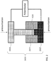
- FIG. 2 is a schematic diagram showing a method for evaluating ion conductivity.
- a pressure-molding die 300 is composed of a frame 301 formed of an electronically insulating polycarbonate, an upper punch part 303 and a lower punch part 302, both of which are formed of electron conductive stainless steel.
- the ion conductivity was evaluated by the following method.
- the inside of the pressure-molding die 300 was filled with the powder of the solid electrolyte material of the inventive example 1, and uniaxially pressed at 400 MPa to produce a conductivity measurement cell of the inventive example 1.
- lead wires were routed from the upper punch part 303 and the lower punch part 302, connected to a potentiostat (Princeton Applied Research, VersaSTAT4) equipped with a frequency response analyzer.
- the ion conductivity at room temperature was measured by an electrochemical impedance measurement method.
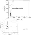
- FIG. 3 shows a Cole-Cole diagram of the results of the impedance measurement.
- the ion conductivity was calculated from the following formula (2) using the resistance value of the electrolyte.
- ⁇ R SE ⁇ S / t ⁇ 1
- S is an electrolyte area (inner diameter of the frame 301 in FIG. 2 )
- R is the resistance value of the solid electrolyte in the above-mentioned impedance measurement
- t is a thickness of the electrolyte (in FIG. 2 , the thickness of the compressed body of the plurality of the solid electrolyte particles 100).
- the ion conductivity of the solid electrolyte material of the inventive example 1 measured at 22 °C was 6.3 ⁇ 10 -4 S / cm.
- the solid electrolyte material of the inventive example 1 and LiCoO 2 (hereinafter, referred to as LCO), which was an active material, were prepared at a volume ratio of 70:30. These were mixed in an agate mortar to prepare a mixture.
- the solid electrolyte material of the inventive example 1 corresponding to 700 ⁇ m thickness, 8.54 mg of the above mixture, and 14.7 mg of Al powder were stacked in this order. This was pressure-molded at a pressure of 300 MPa to provide a first electrode and a solid electrolyte layer.
- a metal In (thickness: 200 ⁇ m) was stacked on the surface of the solid electrolyte layer opposite to the other surface which was in contact with the first electrode. This was pressure-molded at a pressure of 80 MPa to produce a stacking structure composed of the first electrode, the solid electrolyte layer, and a second electrode.
- an insulating ferrule was used to block and seal the inside of the insulating outer cylinder from the outside atmosphere.
- FIG. 4 is a graph showing an initial discharge characteristic.
- the secondary battery of the inventive example 1 was placed in a thermostatic chamber at 25 °C
- the battery was constant-current charged at a current value of 0.05 C rate (20 hour rate) with respect to the theoretical capacity of the battery, and the charge was terminated at a voltage of 3.6 V.
- the battery was discharged at a current value of 0.05 C rate, and the discharge was terminated at a voltage of 2.0 V.
- the initial discharge capacity of the secondary battery of the inventive example 1 was 888 ⁇ Ah.
- raw material powders were prepared in a glove box maintained in a dry / low oxygen atmosphere having a dew point of -90 °C or less and an oxygen value of 5 ppm or less.
- the solid electrolyte materials of the inventive examples 2 to 22 were produced in the same manner as in the inventive example 1.
- each conductivity measurement cell of the inventive examples 2 to 22 was provided in the same manner as in the inventive example 1.
- each solid electrolyte material of the inventive examples 2 to 22 and LiCoO 2 which was a positive electrode active material, were prepared at a volume ratio of 30:70. These were mixed in an agate mortar to produce a positive electrode mixture of each of the inventive examples 2 to 22.
- a charge / discharge test of each of the secondary batteries of the inventive examples 2 to 22 was performed in the same manner as in the inventive example 1.
- the initial discharge characteristic of each of the inventive examples 2 to 22 was similar to that of the inventive example 1, and a good charge / discharge characteristic was provided.
- the ion conductivity measured at 22 °C was 9 ⁇ 10 -6 S / cm.
- the solid electrolyte material of the inventive example 2 was used as a solid electrolyte used for the mixture and the solid electrolyte layer.
- the initial discharge capacity of the secondary battery of the inventive example was not more than 1 ⁇ Ah, and the charge / discharge operation failed to be observed.
- Table 1 shows each configuration and each evaluation result in the inventive examples 1 to 22 and the comparative example 1.
- Composition Anion ⁇ a M Conductivity (S/m) Inventive Example 1 Li 3 Y 0.95 Bi 0.05 Cl 6 Cl 0 0.05 Bi 6.3E-04 Inventive Example 2 Li 3 Y 0.9 Bi 0.1 Cl 6 Cl 0 0.1 Bi 6.0E-04 Inventive Example 3 Li 3 Y 0.5 Bi 0.5 Cl 6 Cl 0 0.5 Bi 1.1E-04 Inventive Example 4 Li 4.5 Y 0.475 Bi 0.025 Cl 6 Cl -0.5 0.025 Bi 6.4E-05 Inventive Example 5 Li 3.9 Y 0.665 Bi 0.035 Cl 6 Cl -0.3 0.035 Bi 1.8E-04 Inventive Example 6 Li 2.4 Y 1.14 Bi 0.06 Cl 6 Cl 0.2 0.06 Bi 5.5E-04 Inventive Example 7 Li 1.5 Y 1.425 Bi 0.075 Cl 6 Cl 0.5 0.075 Bi 6.7E-05 Inventive Example 8 Li 3 Y 0.9 Al 0.1
- inventive examples 1 to 22 show higher ion conductivity of not less than 1 ⁇ 10 -5 S / cm in the vicinity of room temperature, as compared to the comparative example 1.
- a value of a substitution amount a of M defined by the formula (1) is within the range of 0.01 ⁇ a ⁇ 0.99, higher ion conductivity is exhibited.
- a value of a substitution amount a of M defined by the formula (1) is within the range of 0.01 ⁇ a ⁇ 0.99, higher ion conductivity is exhibited.
- ⁇ which indicates an amount of Li deficiency from the stoichiometric ratio thereof, is -0.5 ⁇ ⁇ ⁇ 0.5, higher ion conductivity is exhibited.
- ⁇ is within the range of -0.3 ⁇ ⁇ ⁇ 0.2, higher ion conductivity is exhibited.
- the battery charge / discharge operation was performed at room temperature.
- the discharge capacity was hardly provided, and the battery operation failed to be observed.
- the materials of the inventive examples 1 to 22 do not include sulfur as a constituent element, hydrogen sulfide is not generated.
- the solid electrolyte material according to the present disclosure is an electrolyte material that does not generate hydrogen sulfide, exhibits high lithium ion conductivity, and can perform a good charge / discharge operation.
- the battery of the present disclosure can be used as, for example, an all solid lithium secondary battery.
Landscapes
- Chemical & Material Sciences (AREA)
- Engineering & Computer Science (AREA)
- Chemical Kinetics & Catalysis (AREA)
- Electrochemistry (AREA)
- General Chemical & Material Sciences (AREA)
- Organic Chemistry (AREA)
- Inorganic Chemistry (AREA)
- Manufacturing & Machinery (AREA)
- Materials Engineering (AREA)
- Physics & Mathematics (AREA)
- Condensed Matter Physics & Semiconductors (AREA)
- General Physics & Mathematics (AREA)
- Geology (AREA)
- Life Sciences & Earth Sciences (AREA)
- Secondary Cells (AREA)
- Conductive Materials (AREA)
- Inorganic Compounds Of Heavy Metals (AREA)
- Battery Electrode And Active Subsutance (AREA)
Abstract
Description
- The present disclosure relates to a solid electrolyte material and a battery.
-
Patent Literature 1 discloses an all-solid battery using a sulfide solid electrolyte. - Non-Patent Literature 1 discloses Li3YCl6.
- Non-Patent Literature 2 discloses Li3YBr6.
- Patent Literature 1: Japanese Patent Application Publication No.
2011-129312 -
- Non-patent Literature 1: Z.Anorg.Allg.Chem.623(1997), 1067-1073.
- Non-patent Literature 2: Z.Anorg.Allg.Chem.623(1997), 1352-1356.
- In the prior art, realization of a solid electrolyte material having high lithium ion conductivity is desired.
- The solid electrolyte material in one aspect of the present disclosure is represented by a composition formula Li3-3δY1+δ-aMaCl6-x-yBrxIy,
where
M is at least one element selected from the group consisting of Al, Sc, Ga, and Bi; - -1 < δ < 1;
- 0 < a < 2;
- 0 < (1+δ-a);
- 0 ≤ x ≤ 6;
- 0 ≤ y ≤ 6; and
- (x+y) ≤ 6.
- According to the present disclosure, a solid electrolyte material having high lithium ion conductivity can be realized.
-
-
FIG. 1 is a cross-sectional view showing a schematic configuration of abattery 1000 in a second embodiment. -
FIG. 2 is a schematic diagram showing a method for evaluating ion conductivity. -
FIG. 3 is a graph showing an evaluation result of the ion conductivity by an AC impedance measurement. -
FIG. 4 is a graph showing an initial discharge characteristic. - Hereinafter, embodiments of the present disclosure will be described with reference to the drawings.
- The solid electrolyte material in the first embodiment is a solid electrolyte material represented by the following composition formula (1):
Li3-3δY1+δ-aMaCl6-x-yBrxIy Formula (1)
where M is one or more kinds of elements selected from the group consisting of Al, Sc, Ga, and Bi. - Further,
- -1 < δ < 1;
- 0 < a < 2;
- 0 < (1+δ-a);
- 0 ≤ x ≤ 6;
- 0 ≤ y ≤ 6; and
- (x + y) ≤ 6 are satisfied.
- According to the above configuration, a solid electrolyte material (halide solid electrolyte material) having high lithium ion conductivity can be realized.
- In addition, according to the above configuration, an all-solid secondary battery excellent in a charge / discharge characteristic can be realized by using the solid electrolyte material of the first embodiment. In addition, by using the solid electrolyte material of the first embodiment, an all-solid secondary battery which does not including sulfur can be realized. In other words, the solid electrolyte material of the first embodiment does not have a configuration (for example, the configuration of Patent Literature 1) in which hydrogen sulfide is generated when exposed to the atmosphere. For this reason, an all-solid secondary battery which does not generate hydrogen sulfide and is excellent in safety can be realized.
- In addition, the solid electrolyte material in the first embodiment may satisfy 0.025 ≤ a ≤ 0.99 in the above composition formula (1).
- According to the above configuration, a solid electrolyte material having higher lithium ion conductivity can be realized.
- In addition, the solid electrolyte material in the first embodiment may satisfy 0.035 ≤ a ≤ 0.1 in the above composition formula (1).
- According to the above configuration, a solid electrolyte material having higher lithium ion conductivity can be realized.
- The solid electrolyte material in the first embodiment may satisfy -0.5 ≤ δ ≤ 0.5 in the above composition formula (1).
- According to the above configuration, a solid electrolyte material having higher lithium ion conductivity can be realized.
- The solid electrolyte material in the first embodiment may satisfy -0.3 ≤ δ ≤ 0.2 in the above composition formula (1).
- According to the above configuration, a solid electrolyte material having higher lithium ion conductivity can be realized.
- The solid electrolyte material in the first embodiment may be crystalline or amorphous.
- In addition, a shape of the solid electrolyte material in the first embodiment is not specifically limited, for example, an acicular shape, a spherical shape, or an elliptical spherical shape. For example, the solid electrolyte material in the first embodiment may be particles. After a plurality of the particles are stacked, the plurality of the particles may be formed into a pellet shape or a plate shape by pressurization.
- For example, if the shape of the solid electrolyte material in the first embodiment is particulate (for example, spherical), the median diameter thereof may be not less than 0.1 µm and not more than 100 µm.
- In the first embodiment, the median diameter may be not less than 0.5 µm and not more than 10 µm.
- According to the above configuration, ion conductivity can be further improved. In addition, a better dispersion state of the solid electrolyte material and the active material in the first embodiment can be formed.
- In the first embodiment, the solid electrolyte material may be smaller than the median diameter of the active material.
- According to the above configuration, a better dispersion state of the solid electrolyte material and the active material in the first embodiment can be formed.
- The solid electrolyte material in the first embodiment may be manufactured by the following method, for example.
- Binary halide raw material powders are prepared so as to provide a blending ratio of a target composition. For example, if Li3Y0.95Bi0.05Cl6 is produced, LiCl, YCl3, and BiCl3 are prepared at a molar ratio of approximately 3 : 0.95 : 0.05. In consideration of change in composition during synthesis process, the blending ratio may be adjusted in advance so as to cancel the change. The above-described values "δ", "a", "x", and "y" can be adjusted by adjusting the raw material, the blending ratio, and the synthesis process.
- After the raw material powders are mixed well, the raw material powders are mixed and ground to react by a mechanochemical milling method. Subsequently, the powders may be sintered in a vacuum or an inert atmosphere.
- Alternatively, the raw material powders may be mixed well and then sintered in a vacuum or in an inert atmosphere. For example, it is preferable that the powders are sintered within a range of 100 °C to 650 °C for 1 hour or longer.
- Thereby, the solid electrolyte material including the composition as described above is provided.
- Hereinafter, the second embodiment will be described. The description which has been set forth in the first embodiment is omitted as appropriate.
- The battery in the second embodiment is configured using the solid electrolyte material described in the first embodiment.
- The battery in the second embodiment comprises a solid electrolyte material, a positive electrode, a negative electrode, and an electrolyte layer.
- The electrolyte layer is a layer provided between the positive electrode and the negative electrode.
- At least one of the positive electrode, the electrolyte layer, and the negative electrode includes the solid electrolyte material in the first embodiment.
- According to the above configuration, the charge / discharge characteristic of the battery can be improved.
- A specific example of the battery in the second embodiment will be described below.
-
FIG. 1 is a cross-sectional view showing a schematic configuration of abattery 1000 in the second embodiment. - The
battery 1000 in the second embodiment comprises apositive electrode 201, anegative electrode 203, and anelectrolyte layer 202. - The
positive electrode 201 includes positive electrodeactive material particles 204 andsolid electrolyte particles 100. - The
electrolyte layer 202 is disposed between thepositive electrode 201 and thenegative electrode 203. - The
electrolyte layer 202 includes an electrolyte material (for example, a solid electrolyte material). - The
negative electrode 203 includes negative electrodeactive material particles 205 andsolid electrolyte particles 100. - Each of the
solid electrolyte particles 100 is a particle formed of the solid electrolyte material in the first embodiment or a particle including the solid electrolyte material in the first embodiment as a main component. - The
positive electrode 201 includes a material having a property of storing and releasing metal ions (for example, lithium ions). Thepositive electrode 201 includes, for example, a positive electrode active material (for example, the positive electrode active material particles 204). - Examples of the positive electrode active material include lithium-containing transition metal oxides (e.g., Li(NiCoAl)O2 or LiCoO2), transition metal fluorides, polyanions, fluorinated polyanion materials, transition metal sulfides, transition metal oxyfluorides, transition metal oxysulfides, and transition metal oxynitrides.
- The median diameter of the positive electrode
active material particles 204 may be not less than 0.1 µm and not more than 100 µm. If the median diameter of the positive electrodeactive material particles 204 is less than 0.1 µm, there is a possibility that the positive electrodeactive material particles 204 and the halide solid electrolyte material cannot form a good dispersion state in the positive electrode. As a result, the charge / discharge characteristic of the battery is lowered. In addition, if the median diameter of the positive electrodeactive material particles 204 is more than 100 µm, lithium diffusion in the positive electrodeactive material particles 204 is made slow. As a result, it may be difficult to operate the battery at a high output. - The median diameter of the positive electrode
active material particles 204 may be larger than the median diameter of the halide solid electrolyte material. Thereby, the good dispersion state of the positive electrodeactive material particles 204 and the halide solid electrolyte material can be formed. - With regard to the volume ratio "v : 100-v" between the positive electrode
active material particles 204 and the halide solid electrolyte material included in thepositive electrode 201, 30 ≤ v ≤ 95 may be satisfied. If v < 30, it may be difficult to ensure an energy density of the battery sufficiently. In addition, if v > 95, it may be difficult to operate at high output. - The thickness of the
positive electrode 201 may be not less than 10 µm and not more than 500 µm. If the thickness of the positive electrode is less than 10 µm, it may be difficult to ensure an energy density of the battery sufficiently. In addition, if the thickness of the positive electrode is more than 500 µm, it may be difficult to operate at a high output. - The
electrolyte layer 202 is a layer including an electrolyte material. The electrolyte material is, for example, a solid electrolyte material. In other words, theelectrolyte layer 202 may be a solid electrolyte layer. - The solid electrolyte layer may include the solid electrolyte material in the first embodiment as a main component. In other words, the solid electrolyte layer may include the solid electrolyte material in the first embodiment, for example, at a weight ratio of not less than 50% (not less than 50% by weight) with respect to the entire solid electrolyte layer.
- According to the above configuration, the charge / discharge characteristic of the battery can be further improved.
- In addition, the solid electrolyte layer may include the solid electrolyte material in the first embodiment, for example, at a weight ratio of not less than 70% (not less than 70% by weight) with respect to the entire solid electrolyte layer.
- According to the above configuration, the charge / discharge characteristic of the battery can be further improved.
- The solid electrolyte layer, which may include the solid electrolyte material in the first embodiment as a main component, may further include inevitable impurities. The solid electrolyte layer may include the starting materials used for the synthesis of the solid electrolyte material. The solid electrolyte layer may include by-products or decomposition products generated when the solid electrolyte material is synthesized.
- In addition, the solid electrolyte layer may include the solid electrolyte material in the first embodiment, for example, at a weight ratio of 100% (100% by weight) to the entire solid electrolyte layer, except for the inevitable impurities.
- According to the above configuration, the charge / discharge characteristic of the battery can be further improved.
- As described above, the solid electrolyte layer may be composed only of the solid electrolyte material in the first embodiment.
- Alternatively, the solid electrolyte layer may be composed only of a solid electrolyte material different from the solid electrolyte material in the first embodiment. As the solid electrolyte material different from the solid electrolyte material in the first embodiment, for example, Li2MgX4, Li2FeX4, Li(Al, Ga, In)X4, Li3(Al, Ga, In)X6, or LiI (X: CI, Br, I) may be used.
- The solid electrolyte layer may include simultaneously the solid electrolyte material in the first embodiment and the solid electrolyte material different from the solid electrolyte material in the first embodiment. At this time, both of them may be dispersed uniformly. The layer formed of the solid electrolyte material in the first embodiment and the layer formed of the solid electrolyte material different from the solid electrolyte material in the first embodiment may be sequentially arranged in the stacking direction of the battery.
- The thickness of the solid electrolyte layer may be not less than 1 µm and not more than 1,000 µm. If the thickness of the solid electrolyte layer is less than 1 µm, the possibility that the
positive electrode 201 and thenegative electrode 203 are shortcircuited increases. In addition, if the thickness of the solid electrolyte layer is more than 1,000 µm, it may be difficult to operate at a high output. - The
negative electrode 203 includes a material having a property of storing and releasing metal ions (for example, lithium ions). Thenegative electrode 203 includes, for example, a negative electrode active material (for example, the negative electrode active material particles 205). - As the negative electrode active material, a metal material, a carbon material, an oxide, a nitride, a tin compound, or a silicon compound may be used. The metal material may be a single metal. Alternatively, the metal material may be an alloy. Examples of the metal material include a lithium metal and a lithium alloy. Examples of the carbon material include natural graphite, coke, graphitized carbon, carbon fiber, spherical carbon, artificial graphite, and amorphous carbon. From the viewpoint of capacity density, silicon (Si), tin (Sn), a silicon compound, or a tin compound may be preferably used. If a negative electrode active material having a low average reaction voltage is used, the effect of suppressing electrolysis by the solid electrolyte material in the first embodiment is better exhibited.
- The median diameter of the negative electrode
active material particles 205 may be not less than 0.1 µm and not more than 100 µm. If the median diameter of the negative electrodeactive material particles 205 is less than 0.1 µm, there is a possibility that the negative electrodeactive material particles 205 and thesolid electrolyte particles 100 cannot form a good dispersion state in the negative electrode. Thereby, the charge / discharge characteristic of a battery is lowered. On the other hand, if the median diameter of the negative electrodeactive material particles 205 is more than 100 µm, lithium diffusion in the negative electrodeactive material particles 205 is made slow. As a result, it may be difficult to operate the battery at a high output. - The median diameter of the negative electrode
active material particles 205 may be larger than the median diameter of thesolid electrolyte particles 100. Thereby, the good dispersion state of the negative electrodeactive material particles 205 and the halide solid electrolyte material can be formed. - With regard to the volume ratio "v : 100-v" of the negative electrode
active material particles 205 and thesolid electrolyte particles 100 included in thenegative electrode 203, 30 ≤ v ≤ 95 may be satisfied. If v < 30, it may be difficult to ensure an energy density of the battery sufficiently. In addition, if v > 95, it may be difficult to operate at high output. - The thickness of the
negative electrode 203 may be not less than 10 µm and not more than 500 µm. If the thickness of the negative electrode is less than 10 µm, it may be difficult to ensure an energy density of the battery sufficiently. In addition, if the thickness of the negative electrode is more than 500 µm, it may be difficult to operate at a high output. - At least one of the
positive electrode 201, theelectrolyte layer 202, and thenegative electrode 203 may include a sulfide solid electrolyte or an oxide solid electrolyte for the purpose of improving ion conductivity, chemical stability, or electrochemical stability. As the sulfide solid electrolyte, Li2S-P2S5, Li2S-SiS2, Li2S-B2S3, Li2S-GeS2, Li3.25Ge0.25P0.75S4, or Li10GeP2S12 may be used. As the oxide solid electrolyte, a NASICON solid electrolyte such as LiTi2(PO4)3 and its element substitution products, a (LaLi)TiO3 perovskite solid electrolyte, a LISICON solid electrolyte such as Li14ZnGe4O16, Li4SiO4, LiGeO4 and its element substitution products, a garnet solid electrolyte such as Li7La3Zr2O12 and its element substitution products, Li3N and its H substitution products, and Li3PO4 and its N substitution products may be used. - At least one of the
positive electrode 201, theelectrolyte layer 202, and thenegative electrode 203 may include an organic polymer solid electrolyte for the purpose of increasing ion conductivity. As the organic polymer solid electrolyte, for example, a compound of a polymer compound and a lithium salt can be used. The polymer compound may have an ethylene oxide structure. Due to the ethylene oxide structure, a large amount of lithium salt can be included to further increase the ion conductivity. As the lithium salt, LiPF6, LiBF4, LiSbF6, LiAsF6, LiSO3CF3, LiN(SO2CF3)2, LiN(SO2C2F5)2, LiN(SO2CF3)(SO2C4F9), or LiC(SO2CF3)3 may be used. As the lithium salt, one lithium salt selected from these may be used alone. Alternatively, a mixture of two or more kinds of the lithium salts selected from these may be used as the lithium salt. - At least one of the
positive electrode 201, theelectrolyte layer 202, and thenegative electrode 203 may include a non-aqueous electrolyte solution, a gel electrolyte, or an ionic liquid for the purpose of facilitating exchange of lithium ions and improving the output characteristic of the battery. - The non-aqueous electrolyte solution includes a non-aqueous solvent and a lithium salt dissolved in the non-aqueous solvent. As the non-aqueous solvent, a cyclic carbonate solvent, a chain carbonate solvent, a cyclic ether solvent, a chain ether solvent, a cyclic ester solvent, a chain ester solvent, or a fluorine solvent may be used. Examples of the cyclic carbonate solvent include ethylene carbonate, propylene carbonate, and butylene carbonate. Examples of the chain carbonate solvent include dimethyl carbonate, ethyl methyl carbonate, and diethyl carbonate. Examples of the cyclic ether solvent include tetrahydrofuran, 1,4-dioxane, and 1,3-dioxolane. Examples of the chain ether solvent include 1,2-dimethoxyethane and 1,2-diethoxyethane. Examples of the cyclic ester solvent include γ-butyrolactone. Examples of the chain ester solvent include methyl acetate. Examples of the fluorine solvent include fluoroethylene carbonate, methyl fluoropropionate, fluorobenzene, fluoroethyl methyl carbonate, and fluorodimethylene carbonate. As the non-aqueous solvent, one non-aqueous solvent selected from these may be used alone. Alternatively, a combination of two or more kinds of non-aqueous solvents selected from these may be used as the non-aqueous solvent. The non-aqueous electrolyte solution may include at least one fluorine solvent selected from the group consisting of fluoroethylene carbonate, methyl fluoropropionate, fluorobenzene, fluoroethyl methyl carbonate, and fluorodimethylene carbonate. As the lithium salt, LiPF6, LiBF4, LiSbF6, LiAsF6, LiSO3CF3, LiN(SO2CF3)2, LiN(SO2C2F5)2, LiN(SO2CF3)(SO2C4F9), or LiC(SO2CF3)3 may be used. As the lithium salt, one lithium salt selected from these may be used alone. Alternatively, a mixture of two or more kinds of lithium salts selected from these may be used as the lithium salt. The concentration of the lithium salt is, for example, within a range of 0.5 to 2 mol / liter.
- As the gel electrolyte, a polymer material including the non-aqueous electrolyte solution may be used. As the polymer material, polyethylene oxide, polyacrylonitrile, polyvinylidene fluoride, polymethyl methacrylate, or a polymer having an ethylene oxide bond may be used.
- The cation forming the ionic liquid may be:
- an aliphatic chain quaternary salt such as tetraalkylammonium or tetraalkylphosphonium,
- aliphatic cyclic ammonium such as pyrrolidinium, morpholinium, imidazolinium, tetrahydropyrimidinium, piperazinium, or piperidinium; or
- a nitrogen-containing heterocyclic aromatic cation such as pyridinium or imidazolium.
- An anion forming the ionic liquid is PF6 -, BF4 -, SbF6 -, AsF6 -, SO3CF3 -, N(SO2CF3)2 -, N(SO2C2F5)2 -, N(SO2CF3)(SO2C4F9)-, or C(SO2CF3)3 -. The ionic liquid may include a lithium salt.
- At least one of the
positive electrode 201, theelectrolyte layer 202, and thenegative electrode 203 may include a binder for the purpose of improving the adhesion between the particles. The binder is used to improve the binding property of the material forming the electrode. Examples of the binder include polyvinylidene fluoride, polytetrafluoroethylene, polyethylene, polypropylene, aramid resin, polyamide, polyimide, polyamideimide, polyacrylonitrile, polyacrylic acid, methyl polyacrylate ester, ethyl polyacrylate ester, hexyl polyacrylate ester, polymethacrylic acid, methyl polymethacrylate ester, ethyl polymethacrylate ester, hexyl polymethacrylate ester, polyvinyl acetate, polyvinylpyrrolidone, polyether, polyethersulfone, hexafluoropolypropylene, styrene butadiene rubber, and carboxymethylcellulose. As the binder, a copolymer of two or more kinds of materials selected from tetrafluoroethylene, hexafluoroethylene, hexafluoropropylene, perfluoroalkyl vinyl ether, vinylidene fluoride, chlorotrifluoroethylene, ethylene, propylene, pentafluoropropylene, fluoromethyl vinyl ether, acrylic acid, and hexadiene may be used. In addition, two or more kinds of selected from these may be mixed and used as the binder. - In addition, at least one of the
positive electrode 201 and thenegative electrode 203 may include a conductive agent as necessary. - The conductive agent is used to reduce electrode resistance. Examples of the conductive agent include graphite such as natural graphite or artificial graphite; carbon black such as acetylene black or ketjen black; a conductive fiber such as a carbon fiber or a metal fiber; carbon fluoride; metal powder such as aluminum; conductive whiskers such as zinc oxide or potassium titanate; a conductive metal oxide such as titanium oxide; or a conductive polymer compound such as polyaniline, polypyrrole, or polythiophene. Cost reduction can be achieved by using such a carbon conductive agent as the conductive agent.
- An example of the shape of the battery in the second embodiment is a coin, a cylinder, a prism, a sheet, a button, a flat type, or a stacking structure.
- Hereinafter, details of the present disclosure will be described with reference to inventive examples and comparative example.
- In an argon atmosphere having a dew point of -60 °C or less, raw material powders LiCI, YCl3, and BiCl3 were prepared at a molar ratio of LiCl : YCl3 : BiCl3 = 3 : 0.95 : 0. 05. These were ground and mixed in a mortar. Subsequently, milling processing was performed at 600 rpm for 25 hours using a planetary ball mill.
- In this way, a powder of the solid electrolyte material of the inventive example 1 represented by the composition formula of Li3Y0.95Bi0.05Cl6 was provided.
-
FIG. 2 is a schematic diagram showing a method for evaluating ion conductivity. - A pressure-
molding die 300 is composed of aframe 301 formed of an electronically insulating polycarbonate, anupper punch part 303 and alower punch part 302, both of which are formed of electron conductive stainless steel. - Using the configuration shown in
FIG. 2 , the ion conductivity was evaluated by the following method. - In a dry atmosphere with a dew point of -30 °C or lower, the inside of the pressure-
molding die 300 was filled with the powder of the solid electrolyte material of the inventive example 1, and uniaxially pressed at 400 MPa to produce a conductivity measurement cell of the inventive example 1. - In the pressurized state, lead wires were routed from the
upper punch part 303 and thelower punch part 302, connected to a potentiostat (Princeton Applied Research, VersaSTAT4) equipped with a frequency response analyzer. The ion conductivity at room temperature was measured by an electrochemical impedance measurement method. -
FIG. 3 shows a Cole-Cole diagram of the results of the impedance measurement. - In
FIG. 3 , a real value of the impedance at the measurement point (arrow inFIG. 3 ) having the smallest absolute value of the phase of the complex impedance was deemed to be the resistance value for the ionic conduction of the solid electrolyte of the inventive example 1. - The ion conductivity was calculated from the following formula (2) using the resistance value of the electrolyte.

frame 301 inFIG. 2 ), R is the resistance value of the solid electrolyte in the above-mentioned impedance measurement, and t is a thickness of the electrolyte (inFIG. 2 , the thickness of the compressed body of the plurality of the solid electrolyte particles 100). - The ion conductivity of the solid electrolyte material of the inventive example 1 measured at 22 °C was 6.3 × 10⁻⁴ S / cm.
- In the argon glove box, the solid electrolyte material of the inventive example 1 and LiCoO2 (hereinafter, referred to as LCO), which was an active material, were prepared at a volume ratio of 70:30. These were mixed in an agate mortar to prepare a mixture.
- In an insulating outer cylinder, the solid electrolyte material of the inventive example 1 corresponding to 700 µm thickness, 8.54 mg of the above mixture, and 14.7 mg of Al powder were stacked in this order. This was pressure-molded at a pressure of 300 MPa to provide a first electrode and a solid electrolyte layer.
- Next, a metal In (thickness: 200 µm) was stacked on the surface of the solid electrolyte layer opposite to the other surface which was in contact with the first electrode. This was pressure-molded at a pressure of 80 MPa to produce a stacking structure composed of the first electrode, the solid electrolyte layer, and a second electrode.
- Next, stainless steel current collectors were placed on the upper and lower parts of the stacking structure, and current collector leads were attached to the current collectors.
- Finally, an insulating ferrule was used to block and seal the inside of the insulating outer cylinder from the outside atmosphere.
- In this way, the secondary battery of the inventive example 1 was produced.
-
FIG. 4 is a graph showing an initial discharge characteristic. - The results shown in
FIG. 4 were measured by the following method. - In other words, the secondary battery of the inventive example 1 was placed in a thermostatic chamber at 25 °C
- The battery was constant-current charged at a current value of 0.05 C rate (20 hour rate) with respect to the theoretical capacity of the battery, and the charge was terminated at a voltage of 3.6 V.
- Next, the battery was discharged at a current value of 0.05 C rate, and the discharge was terminated at a voltage of 2.0 V.
- As a result of the above measurement, the initial discharge capacity of the secondary battery of the inventive example 1 was 888 µAh.
- Hereinafter, the synthesis and evaluation methods of Li3-3δY1+δ-aMaCl6-x-yBrxIy will be described.
- In the inventive examples 2 to 22, raw material powders were prepared in a glove box maintained in a dry / low oxygen atmosphere having a dew point of -90 °C or less and an oxygen value of 5 ppm or less.
- In the inventive examples 2 to 17, raw material powders LiCl, YCl3, and MCl3 were prepared at a molar ratio of LiCl : YCl3 : MCl3 = (3-3δ) : (1+δ-a) : a.
- In the inventive example 18, raw material powders LiBr, YBr3, and MBr3 were prepared at a molar ratio of LiBr : YBr3 : MBr3 = (3-3δ) : (1+δ-a) : a.
- In the inventive examples 19 and 20, raw material powders LiCl, YBr3, and MBr3 were prepared at a molar ratio of LiCI : YBr3 : MBr3 = 3: (1-a) : a.
- In the inventive example 21, raw material powders Lil, YBr3, and MBr3 were prepared at a molar ratio of LiI : YBr3 : MBr3 = 3 : 0.95 : 0.05.
- In the inventive example 22, raw material powders LiI, LiBr, YCl3, YBr3, and MBr3 were prepared at a molar ratio of LiI : LiBr : YCl3 : YBr3 : MBr3 = 2 : 1 : 0.6667 : 0.2833 : 0.05.
- The values of "δ" and "a" and the element of "M" in each of the inventive examples 2 to 22 are shown in Table 1.
- The solid electrolyte materials of the inventive examples 2 to 22 were produced in the same manner as in the inventive example 1.
- In a glove box maintained in a dry / low oxygen atmosphere with a dew point of -90 °C or less and an oxygen value of 5 ppm or less, each conductivity measurement cell of the inventive examples 2 to 22 was provided in the same manner as in the inventive example 1.
- Except for this, ion conductivity was measured in the same manner as in the inventive example 1.
- The ion conductivity in each of the inventive examples 2 to 22 is shown in the following Table 1.
- In a glove box maintained in a dry / low oxygen atmosphere with a dew point of -90 °C or less and an oxygen value of 5 ppm or less, each solid electrolyte material of the inventive examples 2 to 22 and LiCoO2, which was a positive electrode active material, were prepared at a volume ratio of 30:70. These were mixed in an agate mortar to produce a positive electrode mixture of each of the inventive examples 2 to 22.
- Except for these, the secondary batteries of the inventive examples 2 to 22 were produced in the same manner as in the inventive example 1.
- A charge / discharge test of each of the secondary batteries of the inventive examples 2 to 22 was performed in the same manner as in the inventive example 1.
- The initial discharge characteristic of each of the inventive examples 2 to 22 was similar to that of the inventive example 1, and a good charge / discharge characteristic was provided.
- LiCl and FeCl2 were used as raw material powders for a solid electrolyte, and mixed at a molar ratio of LiCl : FeCl2 = 2:1.
- Except for this, the synthesis, the evaluation and the analysis were performed in the same manner as in the inventive example 1.
- The ion conductivity measured at 22 °C was 9 × 10⁻⁶ S / cm.
- In addition, the solid electrolyte material of the inventive example 2 was used as a solid electrolyte used for the mixture and the solid electrolyte layer.
- Except for this, a secondary battery was produced and a charge / discharge test was conducted in the same manner as in the inventive example 1.
- The initial discharge capacity of the secondary battery of the inventive example was not more than 1 µAh, and the charge / discharge operation failed to be observed.
- Table 1 shows each configuration and each evaluation result in the inventive examples 1 to 22 and the comparative example 1.
[Table 1] Composition Anion δ a M Conductivity (S/m) Inventive Example 1 Li3Y0.95Bi0.05Cl6 Cl 0 0.05 Bi 6.3E-04 Inventive Example 2 Li3Y0.9Bi0.1Cl6 Cl 0 0.1 Bi 6.0E-04 Inventive Example 3 Li3Y0.5Bi0.5Cl6 Cl 0 0.5 Bi 1.1E-04 Inventive Example 4 Li4.5Y0.475Bi0.025Cl6 Cl -0.5 0.025 Bi 6.4E-05 Inventive Example 5 Li3.9Y0.665Bi0.035Cl6 Cl -0.3 0.035 Bi 1.8E-04 Inventive Example 6 Li2.4Y1.14Bi0.06Cl6 Cl 0.2 0.06 Bi 5.5E-04 Inventive Example 7 Li1.5Y1.425Bi0.075Cl6 Cl 0.5 0.075 Bi 6.7E-05 Inventive Example 8 Li3Y0.9Al0.1Cl6 Cl 0 0.1 Al 4.53E-04 Inventive Example 9 Li3Y0.8Al0.2Cl6 Cl 0 0.2 Al 6.7E-05 Inventive Example 10 Li3Y0.7Al0.3Cl6 Cl 0 0.3 Al 1.7E-05 Inventive Example 11 Li3Y0.95Sc0.05Cl6 Cl 0 0.05 Sc 6.3E-04 Inventive Example 12 Li3Y0.9Sc0.1Cl6 Cl 0 0.1 Sc 5.9E-04 Inventive Example 13 Li3Y0.7Sc0.3Cl6 Cl 0 0.3 Sc 4.0E-04 Inventive Example 14 Li3Y0.5Sc0.5Cl6 Cl 0 0.5 Sc 3.3E-04 Inventive Example 15 Li3Y0.01Sc0.99Cl6 Cl 0 0.99 Sc 1.9E-04 Inventive Example 16 Li3Y0.95Ga0.05Cl6 Cl 0 0.05 Ga 3.6E-04 Inventive Example 17 Li3Y0.9Ga0.1Cl6 Cl 0 0.1 Ga 3.8E-04 Inventive Example 18 Li3Y0.95Bi0.05Br6 Br 0 0.05 Bi 6.2E-04 Inventive Example 19 Li3Y0.5Sc0.5Cl3Br3 Cl, Br 0 0.5 Sc 3.4E-04 Inventive Example 20 Li3Y0.95Bi0.05Cl3Br3 Cl, Br 0 0.05 Bi 1.3E-03 Inventive Example 21 Li3Y0.95Bi 0.05Br3I3 Br, I 0 0.05 Bi 6.7E-04 Inventive Example 22 Li3Y0.95Bi0.05 Cl2Br2I2 Cl, Br, I 0 0.05 Bi 3.0E-03 Comparative Example 1 Li2FeCl4 Cl 9E-06 - It can be seen that the inventive examples 1 to 22 show higher ion conductivity of not less than 1 × 10⁻⁵ S / cm in the vicinity of room temperature, as compared to the comparative example 1.
- In particular, if a value of a substitution amount a of M defined by the formula (1) is within the range of 0.01 ≤ a ≤ 0.99, higher ion conductivity is exhibited. As is clear from the inventive examples 1 to 3 and 8 to 17, if 0.01 ≤ a ≤ 0.5 is satisfied for M=Bi, if 0.01 ≤ a ≤ 0.1 is satisfied for M=AI, if 0.01 ≤ a ≤ 0.99 is satisfied for M=Sc, or if 0.01 ≤ a ≤ 0.1 is satisfied for M=Ga, higher ion conductivity is exhibited.
- Further, if the value of δ, which indicates an amount of Li deficiency from the stoichiometric ratio thereof, is -0.5 ≤ δ ≤ 0.5, higher ion conductivity is exhibited. As is clear from the inventive examples 4 to 7, if the value of δ is within the range of -0.3 ≤ δ ≤ 0.2, higher ion conductivity is exhibited.
- In each of the inventive examples 1 to 22, the battery charge / discharge operation was performed at room temperature. On the other hand, in the comparative example 1, the discharge capacity was hardly provided, and the battery operation failed to be observed. Furthermore, since the materials of the inventive examples 1 to 22 do not include sulfur as a constituent element, hydrogen sulfide is not generated.
- From the above, it is shown that the solid electrolyte material according to the present disclosure is an electrolyte material that does not generate hydrogen sulfide, exhibits high lithium ion conductivity, and can perform a good charge / discharge operation.
- The battery of the present disclosure can be used as, for example, an all solid lithium secondary battery.
-
- 100
- Solid electrolyte particles
- 201
- Positive electrode
- 202
- Electrolyte layer
- 203
- Negative electrode
- 204
- Positive electrode active material particles
- 205
- Negative electrode active material particles
- 300
- Pressure-molding die
- 301
- Frame
- 302
- Lower punch part
- 303
- Upper punch part
- 1000
- Battery
Claims (6)
- A solid electrolyte material represented by a composition formula Li3-3δY1+δ-aMaCl6-x-yBrxIy,
where
M is at least one element selected from the group consisting of Al, Sc, Ga, and Bi;-1 < δ < 1;0 < a < 2;0 < (1+5-a);0 ≤ x ≤ 6;0 ≤ y ≤ 6; and(x+y) ≤ 6. - The solid electrolyte material according to claim 1, wherein
0.025 ≤ a ≤ 0.99 is satisfied. - The solid electrolyte material according to claim 2, wherein
0.035 ≤ a ≤ 0.1 is satisfied. - The solid electrolyte material according to any one of claims 1 to 3, wherein
-0.5 ≤ δ ≤ 0.5 is satisfied. - The solid electrolyte material according to claim 4, wherein
-0.3 ≤ δ ≤ 0.2 is satisfied. - A battery, comprising:a solid electrolyte material according to any one of claims 1 to 5;a positive electrode;a negative electrode; andan electrolyte layer provided between the positive electrode and the negative electrode,whereinat least one selected from the group consisting of the positive electrode, the negative electrode, and the electrolyte layer includes the solid electrolyte material.
Applications Claiming Priority (2)
| Application Number | Priority Date | Filing Date | Title |
|---|---|---|---|
| JP2018000428 | 2018-01-05 | ||
| PCT/JP2018/041897 WO2019135320A1 (en) | 2018-01-05 | 2018-11-13 | Solid electrolyte material and battery |
Publications (2)
| Publication Number | Publication Date |
|---|---|
| EP3736829A1 true EP3736829A1 (en) | 2020-11-11 |
| EP3736829A4 EP3736829A4 (en) | 2021-03-10 |
Family
ID=67143682
Family Applications (1)
| Application Number | Title | Priority Date | Filing Date |
|---|---|---|---|
| EP18898663.2A Withdrawn EP3736829A4 (en) | 2018-01-05 | 2018-11-13 | SOLID ELECTROLYTE MATERIAL AND BATTERY |
Country Status (5)
| Country | Link |
|---|---|
| US (1) | US11784345B2 (en) |
| EP (1) | EP3736829A4 (en) |
| JP (1) | JP7417925B2 (en) |
| CN (1) | CN111448619B (en) |
| WO (1) | WO2019135320A1 (en) |
Cited By (6)
| Publication number | Priority date | Publication date | Assignee | Title |
|---|---|---|---|---|
| EP3890073A4 (en) * | 2018-11-29 | 2022-01-19 | Panasonic Intellectual Property Management Co., Ltd. | NEGATIVE ELECTRODE MATERIAL, BATTERY AND METHOD OF MAKING A BATTERY |
| US11637287B2 (en) | 2018-01-26 | 2023-04-25 | Panasonic Intellectual Property Management Co., Ltd. | Positive electrode material and battery using same |
| US11652235B2 (en) | 2018-01-26 | 2023-05-16 | Panasonic Intellectual Property Management Co., Ltd. | Battery |
| US11682764B2 (en) | 2018-01-26 | 2023-06-20 | Panasonic Intellectual Property Management Co., Ltd. | Cathode material and battery using same |
| US11784345B2 (en) | 2018-01-05 | 2023-10-10 | Panasonic Intellectual Property Management Co., Ltd. | Solid electrolyte material and battery |
| US11955599B2 (en) | 2018-11-29 | 2024-04-09 | Panasonic Intellectual Property Management Co., Ltd. | Negative electrode material and battery |
Families Citing this family (27)
| Publication number | Priority date | Publication date | Assignee | Title |
|---|---|---|---|---|
| JP7228816B2 (en) | 2018-01-05 | 2023-02-27 | パナソニックIpマネジメント株式会社 | Cathode materials and batteries |
| WO2019135345A1 (en) | 2018-01-05 | 2019-07-11 | パナソニックIpマネジメント株式会社 | Solid electrolyte material, and battery |
| JP7281672B2 (en) | 2018-01-05 | 2023-05-26 | パナソニックIpマネジメント株式会社 | battery |
| WO2019135347A1 (en) | 2018-01-05 | 2019-07-11 | パナソニックIpマネジメント株式会社 | Solid electrolyte material and battery |
| WO2019135328A1 (en) | 2018-01-05 | 2019-07-11 | パナソニックIpマネジメント株式会社 | Solid electrolyte material and battery |
| JPWO2019135318A1 (en) | 2018-01-05 | 2021-01-14 | パナソニックIpマネジメント株式会社 | Solid electrolyte material and battery |
| WO2019135316A1 (en) | 2018-01-05 | 2019-07-11 | パナソニックIpマネジメント株式会社 | Solid electrolyte material and battery |
| JP7611524B2 (en) | 2018-01-05 | 2025-01-10 | パナソニックIpマネジメント株式会社 | Solid electrolyte material and battery |
| EP3736834A4 (en) | 2018-01-05 | 2021-03-10 | Panasonic Intellectual Property Management Co., Ltd. | Solid electrolyte material, and battery |
| CN111566756B (en) | 2018-01-26 | 2022-03-08 | 松下知识产权经营株式会社 | Solid electrolyte material and battery |
| KR102595966B1 (en) | 2020-04-14 | 2023-11-01 | 세인트-고바인 세라믹스 앤드 플라스틱스, 인크. | Ion conductive material, electrolyte comprising ion conductive material, and method of forming |
| US11522217B2 (en) | 2020-04-14 | 2022-12-06 | Saint-Gobain Ceramics & Plastics, Inc. | Electrolyte material and methods of forming |
| WO2021209380A1 (en) * | 2020-04-14 | 2021-10-21 | Solvay Sa | New lithium rare-earth halides |
| CN111509222A (en) * | 2020-04-15 | 2020-08-07 | 国联汽车动力电池研究院有限责任公司 | Halide solid electrolyte material and preparation method and application thereof |
| CN115428214B (en) | 2020-04-23 | 2025-08-12 | 圣戈本陶瓷及塑料股份有限公司 | Ion conductive layer and forming method thereof |
| WO2021217045A1 (en) | 2020-04-23 | 2021-10-28 | Saint-Gobain Ceramics & Plastics, Inc. | Ion conductive layer and methods of forming |
| CN115552681A (en) * | 2020-05-28 | 2022-12-30 | 松下知识产权经营株式会社 | Solid electrolyte material and battery using same |
| KR102883985B1 (en) | 2020-07-02 | 2025-11-07 | 삼성전자주식회사 | Solid ion conductor compound, solid electrolyte comprising the same, electrochemical cell comprising the same, and preparation method thereof |
| JP7318140B2 (en) | 2020-08-07 | 2023-07-31 | サン-ゴバン セラミックス アンド プラスティクス,インコーポレイティド | Electrolyte material and forming method |
| US11928472B2 (en) | 2020-09-26 | 2024-03-12 | Intel Corporation | Branch prefetch mechanisms for mitigating frontend branch resteers |
| KR20220064717A (en) | 2020-11-12 | 2022-05-19 | 삼성전자주식회사 | Solid ion conductor compound, solid electrolyte comprising the same, electrochemical cell comprising the same, and preparation method thereof |
| KR20220100297A (en) | 2021-01-08 | 2022-07-15 | 삼성전자주식회사 | Solid ion conductor, solid electrolyte and electrochemical device including the same, and method of preparing the solid ion conductor |
| US12182317B2 (en) | 2021-02-13 | 2024-12-31 | Intel Corporation | Region-based deterministic memory safety |
| KR102637203B1 (en) | 2021-05-17 | 2024-02-19 | 세인트-고바인 세라믹스 앤드 플라스틱스, 인크. | Electrolyte materials and formation methods |
| US12504891B2 (en) | 2021-06-24 | 2025-12-23 | Intel Corporation | Zero-redundancy tag storage for bucketed allocators |
| US12235791B2 (en) | 2021-08-23 | 2025-02-25 | Intel Corporation | Loop driven region based frontend translation control for performant and secure data-space guided micro-sequencing |
| CN117602665A (en) * | 2023-11-28 | 2024-02-27 | 厦门大学 | A kind of preparation method of inorganic solid electrolyte |
Family Cites Families (79)
| Publication number | Priority date | Publication date | Assignee | Title |
|---|---|---|---|---|
| DE3171075D1 (en) | 1980-12-24 | 1985-07-25 | Union Carbide Corp | Composition for use as solid state electrolyte and solid state cell employing same |
| US4352869A (en) | 1980-12-24 | 1982-10-05 | Union Carbide Corporation | Solid state electrolytes |
| US5714279A (en) | 1989-10-24 | 1998-02-03 | The United States Of America As Represented By The Secretary Of The Navy | Non-aqueous lithium cells |
| JP3151925B2 (en) | 1992-05-07 | 2001-04-03 | 松下電器産業株式会社 | Amorphous lithium ion conductive solid electrolyte and its synthesis method |
| US5506073A (en) | 1992-06-22 | 1996-04-09 | Arizona State University (Arizona Board Of Regents, A Body Corporate Acting On Behalf Of Arizona State University) | Lithium ion conducting electrolytes |
| JPH08171938A (en) | 1994-12-15 | 1996-07-02 | Mitsubishi Cable Ind Ltd | Li secondary battery and its positive electrode |
| JPH09293516A (en) | 1996-04-25 | 1997-11-11 | Matsushita Electric Ind Co Ltd | All-solid-state lithium battery |
| JPH11238528A (en) | 1998-02-20 | 1999-08-31 | Ngk Insulators Ltd | Lithium secondary battery |
| WO2000028608A1 (en) | 1998-11-10 | 2000-05-18 | Matsushita Electric Industrial Co., Ltd. | Lithium secondary cell |
| JP2001052733A (en) | 1999-08-05 | 2001-02-23 | Matsushita Electric Ind Co Ltd | All-solid lithium secondary battery |
| KR100513726B1 (en) | 2003-01-30 | 2005-09-08 | 삼성전자주식회사 | Solid electrolytes, batteries employing the same and method for preparing the same |
| JP5076134B2 (en) | 2004-06-08 | 2012-11-21 | 国立大学法人東京工業大学 | Lithium battery element |
| JP5108205B2 (en) | 2005-02-28 | 2012-12-26 | 国立大学法人静岡大学 | All solid-state lithium secondary battery |
| JP4945182B2 (en) * | 2006-07-13 | 2012-06-06 | シャープ株式会社 | Lithium secondary battery and manufacturing method thereof |
| JP2008060033A (en) | 2006-09-04 | 2008-03-13 | Sony Corp | Positive electrode active material, positive electrode and non-aqueous electrolyte secondary battery using the same, and method for producing positive electrode active material |
| JP2008234988A (en) | 2007-03-20 | 2008-10-02 | Sony Corp | Negative electrode and method for producing the same, battery and method for producing the same |
| JP5448038B2 (en) | 2009-02-27 | 2014-03-19 | 公立大学法人大阪府立大学 | Sulfide solid electrolyte material |
| JP2011065982A (en) | 2009-08-18 | 2011-03-31 | Seiko Epson Corp | Lithium battery electrode body and lithium battery |
| JP5141675B2 (en) | 2009-12-16 | 2013-02-13 | トヨタ自動車株式会社 | Method for producing sulfide solid electrolyte material, sulfide solid electrolyte material, and lithium battery |
| JP5510084B2 (en) | 2010-06-03 | 2014-06-04 | ソニー株式会社 | Negative electrode for lithium ion secondary battery, lithium ion secondary battery, electric tool, electric vehicle and power storage system |
| CN102959646B (en) | 2010-06-29 | 2016-02-24 | 丰田自动车株式会社 | Manufacturing method of sulfide solid electrolyte material, manufacturing method of lithium solid battery |
| CN103329319B (en) | 2011-01-27 | 2017-08-29 | 出光兴产株式会社 | Composite material of alkali metal sulfide and conductive agent |
| JP5721540B2 (en) | 2011-05-30 | 2015-05-20 | 株式会社オハラ | Lithium ion conductive inorganic material |
| JP2013073791A (en) | 2011-09-28 | 2013-04-22 | Panasonic Corp | Nonaqueous electrolyte secondary battery |
| US9843071B2 (en) | 2012-07-11 | 2017-12-12 | Toyota Jidosha Kabushiki Kaisha | All-solid-state battery and method for manufacturing the same |
| FR3004467B1 (en) | 2013-04-12 | 2016-05-27 | Saint-Gobain Cristaux Et Detecteurs | FABRICATION OF STOICHIOMETRIC ELPASOLITE |
| FR3005207B1 (en) | 2013-04-24 | 2016-06-24 | Batscap Sa | POSITIVE ELECTRODE FOR LITHIUM BATTERY |
| JP6003831B2 (en) | 2013-06-28 | 2016-10-05 | トヨタ自動車株式会社 | Sulfide solid electrolyte material, sulfide glass, lithium solid battery, and method for producing sulfide solid electrolyte material |
| WO2015011937A1 (en) | 2013-07-25 | 2015-01-29 | 三井金属鉱業株式会社 | Sulfide-based solid electrolyte for lithium ion battery |
| JP2015032529A (en) | 2013-08-06 | 2015-02-16 | トヨタ自動車株式会社 | Sulfide-based solid electrolyte |
| KR102272556B1 (en) | 2013-09-02 | 2021-07-02 | 미츠비시 가스 가가쿠 가부시키가이샤 | Solid-state battery |
| JP6187069B2 (en) | 2013-09-13 | 2017-08-30 | 富士通株式会社 | Lithium battery |
| US10269465B2 (en) | 2013-10-04 | 2019-04-23 | National Institute Of Advanced Industrial Science And Technology | Amorphous (lithium) niobium sulfide or (lithium) titanium niobium sulfide |
| US9431753B2 (en) | 2013-12-30 | 2016-08-30 | Foxconn Interconnect Technology Limited | Connector with convenient installation |
| WO2015136623A1 (en) | 2014-03-11 | 2015-09-17 | 富士通株式会社 | Composite solid electrolyte and all-solid-state battery |
| CN104953175A (en) | 2014-03-28 | 2015-09-30 | 比亚迪股份有限公司 | Solid electrolyte for lithium ion battery, preparation method for solid electrolyte, and lithium ion battery |
| JP5873533B2 (en) | 2014-07-16 | 2016-03-01 | 三井金属鉱業株式会社 | Sulfide-based solid electrolyte for lithium-ion battery |
| US9608288B2 (en) | 2014-07-17 | 2017-03-28 | Samsung Electronics Co., Ltd. | Positive electrode for lithium ion secondary battery and lithium ion secondary battery including the same |
| WO2016075921A1 (en) | 2014-11-10 | 2016-05-19 | ソニー株式会社 | Glass ceramic, lithium-ion conductor, cell, electronic device, and method for manufacturing electrode |
| JP6222134B2 (en) | 2015-02-25 | 2017-11-01 | トヨタ自動車株式会社 | Sulfide solid electrolyte material, battery, and method for producing sulfide solid electrolyte material |
| JP6672848B2 (en) | 2015-03-10 | 2020-03-25 | Tdk株式会社 | Lithium ion conductive oxide ceramic material having garnet type or garnet type similar crystal structure |
| US10218032B2 (en) | 2015-03-10 | 2019-02-26 | Tdk Corporation | Li-ion conductive oxide ceramic material including garnet-type or similar crystal structure |
| US10446872B2 (en) | 2015-08-04 | 2019-10-15 | Samsung Electronics Co., Ltd. | Solid electrolyte and lithium battery including the same |
| JP2017059342A (en) | 2015-09-15 | 2017-03-23 | トヨタ自動車株式会社 | All-solid battery manufacturing method |
| CN107431242B (en) | 2015-09-16 | 2021-03-23 | 松下知识产权经营株式会社 | Battery |
| JP2017091955A (en) | 2015-11-16 | 2017-05-25 | 旭化成株式会社 | Lithium ion conductor and lithium ion battery using the same |
| JP2017091953A (en) | 2015-11-16 | 2017-05-25 | 旭化成株式会社 | Lithium ion conductor and lithium ion battery using the same |
| CN105254184A (en) * | 2015-11-27 | 2016-01-20 | 宁波大学 | A kind of rare earth ion doped Li3YCl6 glass-ceramics and its preparation method |
| JP2017111954A (en) | 2015-12-16 | 2017-06-22 | セイコーエプソン株式会社 | Metal oxide film forming composition, positive electrode composite, positive electrode composite manufacturing method, battery, and battery manufacturing method |
| JP6611949B2 (en) * | 2015-12-22 | 2019-11-27 | トヨタ・モーター・ヨーロッパ | Solid electrolyte materials |
| JP6881892B2 (en) | 2015-12-25 | 2021-06-02 | 三星電子株式会社Samsung Electronics Co.,Ltd. | Manufacturing method of solid electrolyte, all-solid-state battery and solid electrolyte |
| US11245131B2 (en) | 2015-12-25 | 2022-02-08 | Samsung Electronics Co., Ltd. | Solid electrolyte and lithium battery including the same |
| JP6748344B2 (en) | 2016-02-26 | 2020-09-02 | 富士通株式会社 | All solid state battery |
| JPWO2017154922A1 (en) * | 2016-03-08 | 2018-11-22 | 株式会社村田製作所 | Solid electrolyte, all-solid battery, method for producing solid electrolyte, and method for producing all-solid battery |
| JP6658127B2 (en) | 2016-03-10 | 2020-03-04 | セイコーエプソン株式会社 | Solid electrolyte, method for producing solid electrolyte, and lithium ion battery |
| CN105680048B (en) * | 2016-04-05 | 2019-05-17 | 惠州亿纬锂能股份有限公司 | A kind of anode comprising nitrogen-doped graphene, preparation method and the lithium battery using the anode |
| KR102412003B1 (en) | 2016-04-05 | 2022-06-22 | 메사추세츠 인스티튜트 오브 테크놀로지 | Lithium metal electrodes and batteries thereof |
| CN107305965B (en) | 2016-04-25 | 2022-03-29 | 松下知识产权经营株式会社 | Battery and battery manufacturing method |
| JP2017224474A (en) | 2016-06-15 | 2017-12-21 | 出光興産株式会社 | Positive electrode composite |
| CN115036565B (en) | 2016-08-04 | 2025-02-28 | 松下知识产权经营株式会社 | Solid electrolyte materials and batteries |
| CN108258358B (en) | 2016-12-28 | 2022-11-11 | 松下知识产权经营株式会社 | Battery with a battery cell |
| CN107425218B (en) * | 2017-08-04 | 2019-10-15 | 郑州新世纪材料基因组工程研究院有限公司 | A kind of lithium ion solid electrolyte and preparation method thereof, application |
| JPWO2019135318A1 (en) | 2018-01-05 | 2021-01-14 | パナソニックIpマネジメント株式会社 | Solid electrolyte material and battery |
| WO2019135328A1 (en) | 2018-01-05 | 2019-07-11 | パナソニックIpマネジメント株式会社 | Solid electrolyte material and battery |
| WO2019135316A1 (en) | 2018-01-05 | 2019-07-11 | パナソニックIpマネジメント株式会社 | Solid electrolyte material and battery |
| CN111557058B (en) | 2018-01-05 | 2023-09-01 | 松下知识产权经营株式会社 | Solid Electrolyte Materials and Batteries |
| WO2019135320A1 (en) | 2018-01-05 | 2019-07-11 | パナソニックIpマネジメント株式会社 | Solid electrolyte material and battery |
| WO2019135345A1 (en) | 2018-01-05 | 2019-07-11 | パナソニックIpマネジメント株式会社 | Solid electrolyte material, and battery |
| JP7281672B2 (en) | 2018-01-05 | 2023-05-26 | パナソニックIpマネジメント株式会社 | battery |
| JP7228816B2 (en) | 2018-01-05 | 2023-02-27 | パナソニックIpマネジメント株式会社 | Cathode materials and batteries |
| WO2019135347A1 (en) | 2018-01-05 | 2019-07-11 | パナソニックIpマネジメント株式会社 | Solid electrolyte material and battery |
| EP3736834A4 (en) * | 2018-01-05 | 2021-03-10 | Panasonic Intellectual Property Management Co., Ltd. | Solid electrolyte material, and battery |
| JP7611524B2 (en) | 2018-01-05 | 2025-01-10 | パナソニックIpマネジメント株式会社 | Solid electrolyte material and battery |
| EP3736820A4 (en) | 2018-01-05 | 2021-03-10 | Panasonic Intellectual Property Management Co., Ltd. | Solid electrolyte material, and battery |
| JP7316571B2 (en) | 2018-01-05 | 2023-07-28 | パナソニックIpマネジメント株式会社 | solid electrolyte material and battery |
| CN111566756B (en) * | 2018-01-26 | 2022-03-08 | 松下知识产权经营株式会社 | Solid electrolyte material and battery |
| CN111566757B (en) | 2018-01-26 | 2022-08-12 | 松下知识产权经营株式会社 | Solid Electrolyte Materials and Batteries |
| EP3745518B1 (en) | 2018-01-26 | 2022-04-13 | Panasonic Intellectual Property Management Co., Ltd. | Battery |
| WO2020070955A1 (en) | 2018-10-01 | 2020-04-09 | パナソニックIpマネジメント株式会社 | Halide solid electrolyte material and battery using same |
-
2018
- 2018-11-13 WO PCT/JP2018/041897 patent/WO2019135320A1/en not_active Ceased
- 2018-11-13 CN CN201880079441.1A patent/CN111448619B/en active Active
- 2018-11-13 EP EP18898663.2A patent/EP3736829A4/en not_active Withdrawn
- 2018-11-13 JP JP2019563935A patent/JP7417925B2/en active Active
-
2020
- 2020-06-27 US US16/914,335 patent/US11784345B2/en active Active
Cited By (8)
| Publication number | Priority date | Publication date | Assignee | Title |
|---|---|---|---|---|
| US11784345B2 (en) | 2018-01-05 | 2023-10-10 | Panasonic Intellectual Property Management Co., Ltd. | Solid electrolyte material and battery |
| US11637287B2 (en) | 2018-01-26 | 2023-04-25 | Panasonic Intellectual Property Management Co., Ltd. | Positive electrode material and battery using same |
| US11652235B2 (en) | 2018-01-26 | 2023-05-16 | Panasonic Intellectual Property Management Co., Ltd. | Battery |
| US11682764B2 (en) | 2018-01-26 | 2023-06-20 | Panasonic Intellectual Property Management Co., Ltd. | Cathode material and battery using same |
| US12206111B2 (en) | 2018-01-26 | 2025-01-21 | Panasonic Intellectual Property Management Co., Ltd. | Cathode material and battery using same |
| EP3890073A4 (en) * | 2018-11-29 | 2022-01-19 | Panasonic Intellectual Property Management Co., Ltd. | NEGATIVE ELECTRODE MATERIAL, BATTERY AND METHOD OF MAKING A BATTERY |
| US11949064B2 (en) | 2018-11-29 | 2024-04-02 | Panasonic Intellectual Property Management Co., Ltd. | Negative electrode material, battery, and method for producing battery |
| US11955599B2 (en) | 2018-11-29 | 2024-04-09 | Panasonic Intellectual Property Management Co., Ltd. | Negative electrode material and battery |
Also Published As
| Publication number | Publication date |
|---|---|
| US20200328468A1 (en) | 2020-10-15 |
| JPWO2019135320A1 (en) | 2021-01-07 |
| WO2019135320A1 (en) | 2019-07-11 |
| CN111448619A (en) | 2020-07-24 |
| CN111448619B (en) | 2021-11-05 |
| US11784345B2 (en) | 2023-10-10 |
| EP3736829A4 (en) | 2021-03-10 |
| JP7417925B2 (en) | 2024-01-19 |
Similar Documents
| Publication | Publication Date | Title |
|---|---|---|
| US11784345B2 (en) | Solid electrolyte material and battery | |
| EP3736831B1 (en) | Solid electrolyte material and battery | |
| US12209030B2 (en) | Solid electrolyte material and battery | |
| EP3863026B1 (en) | Halide solid electrolyte material and battery using same | |
| EP3863025B1 (en) | Halide solid electrolyte material and battery using this | |
| EP3736820A1 (en) | Solid electrolyte material, and battery | |
| EP3863028A1 (en) | Halide solid electrolyte material and battery using same | |
| EP3736825A1 (en) | Solid electrolyte material and battery | |
| EP3745421A1 (en) | Solid electrolyte material and battery | |
| EP3736828A1 (en) | Solid electrolyte material and battery | |
| EP3736824B1 (en) | Solid electrolyte material and battery | |
| EP3863027B1 (en) | Halide solid electrolyte material and battery using this | |
| EP4044291A1 (en) | Solid electrolyte material and battery using same | |
| EP3904278A1 (en) | Solid electrolyte material and cell using same | |
| EP3933857B1 (en) | Electrolyte material and battery using same | |
| EP3940816B1 (en) | Solid electrolyte material and battery using same | |
| EP3996166A1 (en) | Solid electrolyte material and battery using same | |
| JPWO2020137156A1 (en) | Solid electrolyte and batteries using it | |
| EP3940814B1 (en) | Solid electrolyte material and battery using same | |
| EP3940815B1 (en) | Solid electrolyte material and battery using same |
Legal Events
| Date | Code | Title | Description |
|---|---|---|---|
| STAA | Information on the status of an ep patent application or granted ep patent |
Free format text: STATUS: THE INTERNATIONAL PUBLICATION HAS BEEN MADE |
|
| PUAI | Public reference made under article 153(3) epc to a published international application that has entered the european phase |
Free format text: ORIGINAL CODE: 0009012 |
|
| STAA | Information on the status of an ep patent application or granted ep patent |
Free format text: STATUS: REQUEST FOR EXAMINATION WAS MADE |
|
| 17P | Request for examination filed |
Effective date: 20200527 |
|
| AK | Designated contracting states |
Kind code of ref document: A1 Designated state(s): AL AT BE BG CH CY CZ DE DK EE ES FI FR GB GR HR HU IE IS IT LI LT LU LV MC MK MT NL NO PL PT RO RS SE SI SK SM TR |
|
| AX | Request for extension of the european patent |
Extension state: BA ME |
|
| A4 | Supplementary search report drawn up and despatched |
Effective date: 20210209 |
|
| RIC1 | Information provided on ipc code assigned before grant |
Ipc: H01M 10/052 20100101ALI20210203BHEP Ipc: C01F 17/36 20200101AFI20210203BHEP Ipc: C01G 29/00 20060101ALI20210203BHEP Ipc: H01B 1/06 20060101ALI20210203BHEP Ipc: H01M 10/0562 20100101ALI20210203BHEP Ipc: H01M 4/13 20100101ALI20210203BHEP Ipc: H01M 4/62 20060101ALI20210203BHEP Ipc: C01G 15/00 20060101ALI20210203BHEP |
|
| DAV | Request for validation of the european patent (deleted) | ||
| DAX | Request for extension of the european patent (deleted) | ||
| STAA | Information on the status of an ep patent application or granted ep patent |
Free format text: STATUS: THE APPLICATION HAS BEEN WITHDRAWN |
|
| 18W | Application withdrawn |
Effective date: 20260324 |