EP3736241B1 - Conveying system of an escalator - Google Patents
Conveying system of an escalator Download PDFInfo
- Publication number
- EP3736241B1 EP3736241B1 EP19382337.4A EP19382337A EP3736241B1 EP 3736241 B1 EP3736241 B1 EP 3736241B1 EP 19382337 A EP19382337 A EP 19382337A EP 3736241 B1 EP3736241 B1 EP 3736241B1
- Authority
- EP
- European Patent Office
- Prior art keywords
- riser
- supporting point
- escalator
- transition area
- tread
- Prior art date
- Legal status (The legal status is an assumption and is not a legal conclusion. Google has not performed a legal analysis and makes no representation as to the accuracy of the status listed.)
- Active
Links
Images




Classifications
-
- B—PERFORMING OPERATIONS; TRANSPORTING
- B66—HOISTING; LIFTING; HAULING
- B66B—ELEVATORS; ESCALATORS OR MOVING WALKWAYS
- B66B23/00—Component parts of escalators or moving walkways
- B66B23/14—Guiding means for carrying surfaces
- B66B23/147—End portions, i.e. means for changing the direction of the carrying surface
-
- B—PERFORMING OPERATIONS; TRANSPORTING
- B66—HOISTING; LIFTING; HAULING
- B66B—ELEVATORS; ESCALATORS OR MOVING WALKWAYS
- B66B23/00—Component parts of escalators or moving walkways
- B66B23/08—Carrying surfaces
- B66B23/12—Steps
Definitions
- each step comprises a riser, a tread, a hinge connecting the riser and the tread, a tow roller, and at least a first supporting point and a second supporting point on each side of the step, wherein at the first supporting point the step is connected to the step chain. Further, each step is configured to be folded via the hinge at least during a turnaround in the transition area.
- the invention relates to a conveying system of an escalator and a process to turnaround a step within a conveying system.
- An escalator as known from the state of the art comprises a lower transition area at the lower end of the escalator, an upper transition area at the upper end of the escalator and a transporting area in between the lower and the upper transition area, wherein in the transition areas the steps of the escalator are turned around.
- the escalator requires a pit of approximately 1 meter in depth.
- the WO 2010/115317 A1 discloses a step route structure for controlling the folding and unfolding of foldable steps comprises a main wheel rail, an auxiliary wheel control rail, a folding control rail and a stopper rail that pushes a latch hook stopper in the direction of a releasing lock of a latch hook.
- An inner lateral surface of the auxiliary wheel control rail facing the foldable steps is provided with a rail groove that is matched with an auxiliary wheel of the foldable steps.
- An inner lateral surface of the folding control rail is provided with a control pin sliding groove that is matched with a support arm control pin of the foldable steps.
- the stopper rail is provided opposite to the latch hook stopper of the foldable steps.
- the structure can control the folding and unfolding of the foldable steps, and ensures the surfaces of the steps maintain a horizontal state as the steps fold and unfold.
- the steps are folded twice via two different hinges at two different supporting points of the step.
- the riser shaft is attached to the riser.
- the riser shaft is guided in a curved sliding guide, which is placed between a supporting point of the tread and a supporting point at the lower end of the riser. This is therefore a structurally complicated design, with the step having to be folded twice, which increases the risk of material failure.
- the EP 1 072 552 A1 discloses a conveying system constructed to reduce the depth of the pit in the lower transition area and the upper transition area of an escalator. Thereat, the steps of the conveying system are folded. In the transition areas, the steps are not turned around but guided in a way, that at any position the tread of a step faces upwards. By doing so, the depth of the pit can be reduced, but by guiding the steps in a way, that the tread of a step always faces upwards leads to an enormous increasing of the length of the pit.
- the objective task of the invention is to provide a conveying system for an escalator to reduce the depth of the pit of an escalator without increasing the length of the pit.
- the construction of the escalator should be simple and should not require high costs.
- the construction of a typical escalator should not be changed in large parts, so a large part of standard components can be used.
- each step comprises a riser, a tread, and a hinge connecting the riser and the tread. Further, each step comprises a tow roller, at least a first supporting point, and a second supporting point on each side of the step. At the first supporting point, the step is configured to be connected to a step chain of the escalator. Further, each step is configured to be folded via the hinge at least during a turnaround in a transition area of the escalator.
- the riser of each step comprises at least a curved sliding guide to guide the riser in a predetermined curve while folding the step, especially while folding the step during the turnaround.
- the tow roller is adjusted to the step at the second supporting point the step. Via the tow roller, the step is guided circulating along a tow roller guide of the conveying system.
- the step is configured to be connected to the step chain in a fixed manner at the first supporting point.
- each step comprises a third supporting point.
- the step is configured to be connected via a riser shaft to the step chain in a lose manner. This lose connection of the step to the step chain via the riser shaft enables a controlled folding of the step, wherein the riser is folded towards the tread.
- the supporting points of the step are arranged at each side of the step.
- the first supporting point is arranged at a front edge of the tread.
- the second supporting point is arranged in a mid-region of the tread.
- the third supporting point is arranged at the riser, wherein the riser is arranged at a rear edge of the tread.
- the third supporting point is arranged at each side of the step and in a mid-region of the step width.
- the riser shaft comprises a wheel.
- the wheel is configured to roll within the curved sliding guide of the riser.
- the riser shaft is arranged within the curved sliding guide of the riser.
- the wheel adjusted to the riser shaft enables a frictionless sliding during folding of the step.
- the riser shaft is configured to be connected to the step chain via a special fitting.
- the fitting comprises especially a threaded fixed to the step chain and a connecting nut, fitting on the threaded. This fitting enables a quick and easy mounting and dismounting of the step to the step chain.
- the riser comprises a riser stiffener.
- the riser stiffener is arranged at the lower edge of the riser.
- the riser stiffener has the function to make the riser of the step more rigid to avoid a damage of the riser and thus an appearance of a gap between adjacent steps due to a damage.
- the thickness of the riser can be increased to prevent a damage of the riser.
- the solution of the problem further provides a conveying system of an escalator, wherein the conveying system comprises a transition area, a step chain, and a plurality of steps.
- the steps are connected to the step chain in a fixed manner at a first supporting point.
- the steps are connected via a riser shaft to the step chain in a lose manner at a third supporting point.
- the riser shaft connected to the step chain via a special fitting as described above.
- the step chain comprises inner rollers and outer rollers.
- an outer roller is adjusted to the step chain at least at the first supporting point of each step.
- the inner rollers and outer rollers are guided in a precision guide rail.
- the inner rollers are guided along an inner roller running surface of the precision guide rail.
- the outer rollers are spaced to an outer roller running surface of the precision guide rail.
- at least an outer roller gets in contact with the outer roller running surface in case of a rotation of a step.
- the tow rollers adjusted to the second supporting point of the steps are guided by the precision guide rail.
- the solution of the problem further provides a process to turnaround a step configured as described above within a conveying system as described above, wherein for turnaround the step in the transition area the riser is fold towards the lower side of the tread via the hinge.
- the riser is guided in a predetermined curve defined by the curved sliding guide of the riser.
- the riser is turned around the riser shaft, wherein the wheel of the riser shaft rolls within the curved sliding guide.
- the step is connected to the step chain at the first supporting point in a fixed manner and at the third supporting point the step is connected to the step chain in a lose manner via the riser shaft. Due to the step chain trajectory during the turnaround within the transition area and the riser shaft sliding in the curved sliding guide, the riser of the step is fold automatically towards the lower side of the tread while entering into the turnaround.
- the riser is guided in the predetermined curve defined by the curved sliding guide. Especially the riser shaft slides within the curved sliding guide.
- the riser of each step comprises at least a curved sliding guide to guide the riser in a predetermined curve while folding the step enables a turnaround in the transition area of an escalator with a very small turning radius, wherein the riser is kept in a controlled distance to an adjacent step during the folding and unfolding of the step.
- most components of a typical escalator does not need to be changed when using the steps according the invention.
- Fig. 1 shows a schematic diagram of a conveying system 10 in the lower end of an escalator according the invention.
- the conveying system 10 comprises a transition area 11, a step chain 12 and a plurality of steps 20.
- the steps 20 of the escalator are turned around.
- Each step 20 comprises a tread and a riser, wherein the tread and the riser are connected to each other via a hinge see Fig. 2 .
- the steps 20 When leaving a transporting area of the escalator and entering the transition area 11 at one end of the escalator the steps 20 are guided in a way, so the treads of the steps 20 are in a plane before they are turned around to be returned to the other end of the escalator.
- Each step 20 is configured to be folded via the hinge at least during a turnaround in the transition area 11.
- the riser of a step is folded towards the lower side of the tread of the step.
- the turning radius can be reduced. Accordingly, the depth of the escalator pit can be reduced.
- Fig. 2a and Fig. 2b show a step of the conveying system of Fig. 1 .
- Fig. 2a shows the step 20 in a transporting configuration, wherein the step 20 is unfolded.
- Fig. 2b shows the step 20 in a folded state.
- the step 20 comprises a tread 21, a riser 22 and a hinge 23 connecting the tread 21 and the riser 22 to one another.
- Fig. 3a to Fig. 3d show a detailed view of the steps 20. Thereat, Fig. 3a and Fig. 3b show the steps 20 from an upper side while Fig. 3c and Fig. 3d show the steps 20 from a lower side.
- Each step 20 comprises a first supporting point 24 and a second supporting point 25 on each side of the step.
- the step 20 is connected to the step chain 12 in a fixed manner.
- a tow roller 251 is adjusted to the step 20.
- the riser 22 of each step 20 comprises at least a curved sliding guide 221.
- the curved sliding guide 221 is configured to guide the riser 22 in a predetermined curve while folding the step 20 during the turnaround in the transition area.
- the shape of the curved sliding guide 221 is adapted such that a controlled distance is kept between the riser 22 and the adjacent step 20 during the turnaround. In that way, collisions are avoided between adjacent steps 20 during the turnaround.
- each step 20 comprises a third supporting point 26, wherein at the third supporting point 26, the step 20 is connected via a riser shaft 261 to the step chain 12 in a lose manner.
- the riser shaft 261 comprises a wheel 262, wherein the wheel 262 is configured to roll within the curved sliding guide 221 of the riser 22.
- the step chain 12 comprises inner rollers 121 and outer rollers 122.
- the inner rollers 121 and outer rollers 122 are guided in a precision guide rail (see Fig. 4a and Fig. 4b ).
- Fig. 4a and Fig. 4b show a detailed view of the first supporting point 24 of a step 20.
- Fig. 4a shows a detailed view of the connection of the outer roller 122 and inner roller 121 to the first supporting point 24 of the step 20.
- Fig. 4b shows a detailed view of the guidance of the inner roller 121 and outer roller 122 of the step chain 12, as well as the guidance of the tow roller 251 of the step 20.
- an outer roller 122 is adjusted to the step chain 12.
- the inner rollers 121 and outer rollers 122 of the step chain 12 are guided in a precision guide rail 13. Thereat, the inner rollers 121 are in contact with the inner roller running surface 131.
- the outer rollers 122 are spaced to the outer roller running surface 132.
- the tow roller 251 adjusted to the second supporting point 25 of the step 25 is guided by the precision guide rail 13.
- the tow roller 251 is in contact with the inner roller running surface 131.
- Fig. 5 shows a closer view of Fig. 3c .
- the riser 22 of each step 20 comprises a riser stiffener 222.
- the riser stiffener 222 has the function to make the riser 22 of the step 20 more rigid to avoid a damage of the riser 22 and thus an appearance of a gap between adjacent steps 20 due to a damage.
- the thickness of the riser 22 can be increased to prevent a damage of the riser 22.
- Fig. 6 shows a transition area 11 in which the steps 20 are turned around.
- the tow rollers of the steps are guided around a curved guide rail of a small turning radius such that the depth of the pit can be reduced especially such that the depth d of the pit is reduced to d ⁇ 1m.
- the riser 22 of the step 20 is fold towards the lower side of the tread 21 via the hinge. While folding, the riser 22 is guided in a predetermined curve defined by the curved sliding guide 221, wherein the wheel 262 of the riser shaft 261 rolls within the curved sliding guide 221.
- the step 20 folds automatically when guided through the turnaround according the trajectory of the step chain 12 due to the step 20 is connected to the step chain at the first supporting point in a fixed manner and at the third supporting point the step is connected to the step chain 12 in a lose manner via the riser shaft 261.
- the riser 22 is folded towards the lower side of the tread 21. Equivalent, when leaving the transition area 11, the step 20 unfolds automatically due to the trajectory of the step chain 12.
- the riser 22 guided is guided in the predetermined curve defined by the curved sliding guide 221 of the riser 22. Thereat, the riser 22 is turned around the riser shaft 261, wherein the wheel 262 of the riser shaft 261 rolls within the curved sliding guide 221.
- the riser shaft 261 is connected to the step chain 12 via a special fitting 263.
- the fitting 263 comprises an outer thread 2631 fixed to the step chain 12 and a connecting nut 2632, fitting on the outer thread 2631.
- the fitting 263 enables an easy connecting and disconnecting of the riser shaft to the step chain and therefore an easy mount and dismount of the step to the conveying system of the escalator.
Landscapes
- Escalators And Moving Walkways (AREA)
Description
- The invention relates to a step for a conveying system of an escalator. Thereat, each step comprises a riser, a tread, a hinge connecting the riser and the tread, a tow roller, and at least a first supporting point and a second supporting point on each side of the step, wherein at the first supporting point the step is connected to the step chain. Further, each step is configured to be folded via the hinge at least during a turnaround in the transition area.
- Further, the invention relates to a conveying system of an escalator and a process to turnaround a step within a conveying system.
- An escalator as known from the state of the art comprises a lower transition area at the lower end of the escalator, an upper transition area at the upper end of the escalator and a transporting area in between the lower and the upper transition area, wherein in the transition areas the steps of the escalator are turned around.
- To provide enough space for a turnaround of the steps the escalator requires a pit of approximately 1 meter in depth.
- In some cases it could be necessary to reduce the pit size e.g. if there are specific installations underneath the escalator which require space such as a garage or a piping system, or if the escalator has to be installed in an existing building and the effort to provide a large pit is very high. It could also be very interesting to reduce the pit size of escalators used for barking and debarking passengers from an airplane, wherein the escalator is usually transported in a truck.
- Therefore, it is desirable to reduce the depth of the pit, especially to reduce the turning radius of the turnaround of the steps within the pit, especially for the lower transition area of an escalator.
- The
WO 2010/115317 A1 discloses a step route structure for controlling the folding and unfolding of foldable steps comprises a main wheel rail, an auxiliary wheel control rail, a folding control rail and a stopper rail that pushes a latch hook stopper in the direction of a releasing lock of a latch hook. An inner lateral surface of the auxiliary wheel control rail facing the foldable steps is provided with a rail groove that is matched with an auxiliary wheel of the foldable steps. An inner lateral surface of the folding control rail is provided with a control pin sliding groove that is matched with a support arm control pin of the foldable steps. The stopper rail is provided opposite to the latch hook stopper of the foldable steps. The structure can control the folding and unfolding of the foldable steps, and ensures the surfaces of the steps maintain a horizontal state as the steps fold and unfold. In this state of the art the steps are folded twice via two different hinges at two different supporting points of the step. in this context, the riser shaft is attached to the riser. During folding the riser shaft is guided in a curved sliding guide, which is placed between a supporting point of the tread and a supporting point at the lower end of the riser. This is therefore a structurally complicated design, with the step having to be folded twice, which increases the risk of material failure. - The
EP 1 072 552 A1 discloses a conveying system constructed to reduce the depth of the pit in the lower transition area and the upper transition area of an escalator. Thereat, the steps of the conveying system are folded. In the transition areas, the steps are not turned around but guided in a way, that at any position the tread of a step faces upwards. By doing so, the depth of the pit can be reduced, but by guiding the steps in a way, that the tread of a step always faces upwards leads to an enormous increasing of the length of the pit. - Therefore, the objective task of the invention is to provide a conveying system for an escalator to reduce the depth of the pit of an escalator without increasing the length of the pit. Thereat, the construction of the escalator should be simple and should not require high costs. Especially, the construction of a typical escalator should not be changed in large parts, so a large part of standard components can be used.
- To solve the problem a step for a conveying system of an escalator, a conveying system of an escalator, as well as a process to turnaround a step within a conveying system are proposed according the independent claims.
- Further, advantageous arrangements of the invention are described in the dependent claims and the description as well as shown in the figures.
- The solution of the problem provides a step for a conveying system of an escalator. Therein, each step comprises a riser, a tread, and a hinge connecting the riser and the tread. Further, each step comprises a tow roller, at least a first supporting point, and a second supporting point on each side of the step. At the first supporting point, the step is configured to be connected to a step chain of the escalator. Further, each step is configured to be folded via the hinge at least during a turnaround in a transition area of the escalator.
- Especially, the riser of each step comprises at least a curved sliding guide to guide the riser in a predetermined curve while folding the step, especially while folding the step during the turnaround.
- By guiding the riser in a predetermined curve by the curved sliding guide, collisions are avoided between adjacent steps.
- In an arrangement, the tow roller is adjusted to the step at the second supporting point the step. Via the tow roller, the step is guided circulating along a tow roller guide of the conveying system.
- In a further arrangement, the step is configured to be connected to the step chain in a fixed manner at the first supporting point.
- In a further arrangement, each step comprises a third supporting point. Especially, at the third supporting point, the step is configured to be connected via a riser shaft to the step chain in a lose manner. This lose connection of the step to the step chain via the riser shaft enables a controlled folding of the step, wherein the riser is folded towards the tread.
- In a further arrangement the supporting points of the step are arranged at each side of the step. Especially, the first supporting point is arranged at a front edge of the tread. Especially, the second supporting point is arranged in a mid-region of the tread. Especially, the third supporting point is arranged at the riser, wherein the riser is arranged at a rear edge of the tread. Especially, the third supporting point is arranged at each side of the step and in a mid-region of the step width.
- In a further arrangement, the riser shaft comprises a wheel. Especially, the wheel is configured to roll within the curved sliding guide of the riser.
- So, the riser shaft is arranged within the curved sliding guide of the riser. The wheel adjusted to the riser shaft enables a frictionless sliding during folding of the step.
- In a further arrangement, the riser shaft is configured to be connected to the step chain via a special fitting. The fitting comprises especially a threaded fixed to the step chain and a connecting nut, fitting on the threaded. This fitting enables a quick and easy mounting and dismounting of the step to the step chain.
- In a further arrangement, the riser comprises a riser stiffener. Especially, the riser stiffener is arranged at the lower edge of the riser.
- In case that the riser of a step is dented, a gap could appear between adjacent steps. The riser stiffener has the function to make the riser of the step more rigid to avoid a damage of the riser and thus an appearance of a gap between adjacent steps due to a damage.
- Additionally or alternatively, the thickness of the riser can be increased to prevent a damage of the riser.
- The solution of the problem further provides a conveying system of an escalator, wherein the conveying system comprises a transition area, a step chain, and a plurality of steps. Especially, the steps are connected to the step chain in a fixed manner at a first supporting point. Especially, the steps are connected via a riser shaft to the step chain in a lose manner at a third supporting point. Especially, the riser shaft connected to the step chain via a special fitting as described above.
- In an arrangement, the step chain comprises inner rollers and outer rollers. Especially, an outer roller is adjusted to the step chain at least at the first supporting point of each step. Especially, the inner rollers and outer rollers are guided in a precision guide rail. Especially, the inner rollers are guided along an inner roller running surface of the precision guide rail. Especially, the outer rollers are spaced to an outer roller running surface of the precision guide rail. Especially, at least an outer roller gets in contact with the outer roller running surface in case of a rotation of a step.
- In a further arrangement, the tow rollers adjusted to the second supporting point of the steps are guided by the precision guide rail.
- Guiding the step chain via the inner rollers and outer rollers, as well as guiding the tow rollers of the steps by the precision guide rail leads to an increasing of stability.
- In case a user is standing over the rear edge of a step the main part of the weight force acting on the step due to the user is acting on the first supporting point in an upward direction and on the second supporting point in a downward direction creating a rotation momentum in the step. In case of an occurrence of a rotation of a step, at least an outer roller gets in contact with the outer roller running surface of the precision guide rail. Accordingly, the rotation is reduced by the precision guide rail, increasing significantly the stability of the step.
- The solution of the problem further provides a process to turnaround a step configured as described above within a conveying system as described above, wherein for turnaround the step in the transition area the riser is fold towards the lower side of the tread via the hinge.
- Especially, while folding, the riser is guided in a predetermined curve defined by the curved sliding guide of the riser. Especially, the riser is turned around the riser shaft, wherein the wheel of the riser shaft rolls within the curved sliding guide.
- The step is connected to the step chain at the first supporting point in a fixed manner and at the third supporting point the step is connected to the step chain in a lose manner via the riser shaft. Due to the step chain trajectory during the turnaround within the transition area and the riser shaft sliding in the curved sliding guide, the riser of the step is fold automatically towards the lower side of the tread while entering into the turnaround.
- Equivalent, when leaving the transition area, the step unfolds automatically due to the trajectory of the step chain.
- In a further implementation during unfolding the step, the riser is guided in the predetermined curve defined by the curved sliding guide. Especially the riser shaft slides within the curved sliding guide.
- In that way, collisions between adjacent steps are avoided.
- The special arrangement of the step according the invention, wherein the riser of each step comprises at least a curved sliding guide to guide the riser in a predetermined curve while folding the step enables a turnaround in the transition area of an escalator with a very small turning radius, wherein the riser is kept in a controlled distance to an adjacent step during the folding and unfolding of the step. Thereat, most components of a typical escalator does not need to be changed when using the steps according the invention.
- Further, positive details, features and functions of the invention are explained in association with the examples shown in the figures.
- It is shown in:
- Fig. 1
- in a schematic diagram showing a transition area of a conveying system of an escalator;
- Fig. 2
- in schematic diagrams a step of the conveying system:
- a in an unfolded state;
- b in a folded state;
- Fig. 3
- in detailed diagrams the steps of the conveying system out of different perspectives, wherein the steps are shown:
- a in a side view;
- b in a detailed view the side view shown in
Fig. 3a ; - c in a bottom-up view;
- d in a detailed view the bottom-up view shown in
Fig. 3c ;
- Fig. 4
- in a detailed view at the first supporting point of a step:
- a the connection of the outer roller and inner roller to the first supporting point;
- b the guidance of the inner roller and outer roller of the step chain, as well as the guidance of the tow roller of the step;
- Fig. 5
- in a closer more detailed view the steps shown in
Fig. 3c ; - Fig. 6
- in a schematic diagram a transition area of the conveying system; and
- Fig. 7
- in a schematic diagram a fitting of a riser shaft.
-
Fig. 1 shows a schematic diagram of a conveyingsystem 10 in the lower end of an escalator according the invention. - The conveying
system 10 comprises atransition area 11, astep chain 12 and a plurality ofsteps 20. In thetransition area 11, thesteps 20 of the escalator are turned around. - Each
step 20 comprises a tread and a riser, wherein the tread and the riser are connected to each other via a hinge seeFig. 2 . - When leaving a transporting area of the escalator and entering the
transition area 11 at one end of the escalator thesteps 20 are guided in a way, so the treads of thesteps 20 are in a plane before they are turned around to be returned to the other end of the escalator. - Each
step 20 is configured to be folded via the hinge at least during a turnaround in thetransition area 11. - During a turnaround, especially during the turnaround in a
lower transition area 11 at the lower end of the escalator, the riser of a step is folded towards the lower side of the tread of the step. - By folding the steps during the turnaround, the turning radius can be reduced. Accordingly, the depth of the escalator pit can be reduced.
-
Fig. 2a and Fig. 2b show a step of the conveying system ofFig. 1 . Thereat,Fig. 2a shows thestep 20 in a transporting configuration, wherein thestep 20 is unfolded.Fig. 2b shows thestep 20 in a folded state. - The
step 20 comprises atread 21, ariser 22 and ahinge 23 connecting thetread 21 and theriser 22 to one another. -
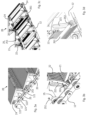
Fig. 3a to Fig. 3d show a detailed view of thesteps 20. Thereat,Fig. 3a and Fig. 3b show thesteps 20 from an upper side whileFig. 3c and Fig. 3d show thesteps 20 from a lower side. - Each
step 20 comprises a first supportingpoint 24 and a second supportingpoint 25 on each side of the step. At the first supportingpoint 24, thestep 20 is connected to thestep chain 12 in a fixed manner. At the second supportingpoint 25, atow roller 251 is adjusted to thestep 20. - The
riser 22 of eachstep 20 comprises at least a curved slidingguide 221. The curved slidingguide 221 is configured to guide theriser 22 in a predetermined curve while folding thestep 20 during the turnaround in the transition area. - The shape of the curved sliding
guide 221 is adapted such that a controlled distance is kept between theriser 22 and theadjacent step 20 during the turnaround. In that way, collisions are avoided betweenadjacent steps 20 during the turnaround. - Further, each
step 20 comprises a third supportingpoint 26, wherein at the third supportingpoint 26, thestep 20 is connected via ariser shaft 261 to thestep chain 12 in a lose manner. - The
riser shaft 261 comprises awheel 262, wherein thewheel 262 is configured to roll within the curved slidingguide 221 of theriser 22. - As can be seen in
Fig. 3a , thestep chain 12 comprisesinner rollers 121 andouter rollers 122. Theinner rollers 121 andouter rollers 122 are guided in a precision guide rail (seeFig. 4a and Fig. 4b ). -
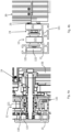
Fig. 4a and Fig. 4b show a detailed view of the first supportingpoint 24 of astep 20. Thereat,Fig. 4a shows a detailed view of the connection of theouter roller 122 andinner roller 121 to the first supportingpoint 24 of thestep 20.Fig. 4b shows a detailed view of the guidance of theinner roller 121 andouter roller 122 of thestep chain 12, as well as the guidance of thetow roller 251 of thestep 20. - At the first supporting
point 24 of thestep 20, anouter roller 122 is adjusted to thestep chain 12. Theinner rollers 121 andouter rollers 122 of thestep chain 12 are guided in aprecision guide rail 13. Thereat, theinner rollers 121 are in contact with the innerroller running surface 131. Theouter rollers 122 are spaced to the outerroller running surface 132. - Further, the
tow roller 251 adjusted to the second supportingpoint 25 of thestep 25 is guided by theprecision guide rail 13. Thetow roller 251 is in contact with the innerroller running surface 131. - In case a user is standing over the rear edge of a step the main part of the weight force acting on the step due to the user is acting on the first supporting point in an upward direction and on the second supporting point in a downward direction creating a rotation momentum in the step.
- In case of an occurrence of a rotation of a
step 20, at least anouter roller 122 gets in contact with the outerroller running surface 132 of theprecision guide rail 13. - Accordingly, the rotation of the
step 20 is reduced by theprecision guide rail 13, increasing significantly the stability of thestep 20. -
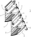
Fig. 5 shows a closer view ofFig. 3c . Thereat, theriser 22 of eachstep 20 comprises ariser stiffener 222. - The
riser stiffener 222 has the function to make theriser 22 of thestep 20 more rigid to avoid a damage of theriser 22 and thus an appearance of a gap betweenadjacent steps 20 due to a damage. - Additionally or alternatively, the thickness of the
riser 22 can be increased to prevent a damage of theriser 22. -
Fig. 6 shows atransition area 11 in which thesteps 20 are turned around. - During the turnaround the tow rollers of the steps are guided around a curved guide rail of a small turning radius such that the depth of the pit can be reduced especially such that the depth d of the pit is reduced to d<1m.
- For turnaround a
step 20 in thetransition area 11 theriser 22 of thestep 20 is fold towards the lower side of thetread 21 via the hinge. While folding, theriser 22 is guided in a predetermined curve defined by the curved slidingguide 221, wherein thewheel 262 of theriser shaft 261 rolls within the curved slidingguide 221. - The
step 20 folds automatically when guided through the turnaround according the trajectory of thestep chain 12 due to thestep 20 is connected to the step chain at the first supporting point in a fixed manner and at the third supporting point the step is connected to thestep chain 12 in a lose manner via theriser shaft 261. - Therefore, when entering the
transition area 11, theriser 22 is folded towards the lower side of thetread 21. Equivalent, when leaving thetransition area 11, thestep 20 unfolds automatically due to the trajectory of thestep chain 12. - During unfolding, the
riser 22 guided is guided in the predetermined curve defined by the curved slidingguide 221 of theriser 22. Thereat, theriser 22 is turned around theriser shaft 261, wherein thewheel 262 of theriser shaft 261 rolls within the curved slidingguide 221. - As shown in
Fig. 7 , theriser shaft 261 is connected to thestep chain 12 via aspecial fitting 263. - The fitting 263 comprises an
outer thread 2631 fixed to thestep chain 12 and a connectingnut 2632, fitting on theouter thread 2631. - The fitting 263 enables an easy connecting and disconnecting of the riser shaft to the step chain and therefore an easy mount and dismount of the step to the conveying system of the escalator.
-
- 10
- Conveying system
- 11
- transition area
- 12
- Step chain
121 Inner roller
122 Outer roller - 13
- Precision guide rail
131 Inner roller running surface
132 Outer roller running surface - 20
- Step
- 21
- Tread
- 22
- Riser
221 Curved sliding guide
222 Riser stiffener - 23
- Hinge
- 24
- First supporting point
- 25
- Second supporting point
251 Tow roller - 26
- Third supporting point
261 Riser shaft
262 Wheel
263 Fitting
2631 Outer thread
2632 Connecting nut
Claims (15)
- Step (20) for a conveying system (10) of an escalator, whereineach step (20) comprises:- a riser (22),- a tread (21),- a hinge (23) connecting the riser (22) and the tread (21),- a tow roller (251),- at least a first supporting point (24) and a second supporting point (25) on each side of the step (20), whereinand wherein
at the first supporting point (24), the step (20) is configured to be connected to a step chain (12) of the escalator,each step (20) is configured to be folded via the hinge (23) at least during a turnaround in a transition area (11) of the escalator,characterized inthat the riser (22) of each step (20) comprises at least a curved sliding guide (221) to guide the riser (22) in a predetermined curve while folding the step (20). - Step (20) of claim 1,
characterized in
that the tow roller (251) is adjusted to the step (20) at the second supporting point (25) of the step (20). - Step (20) of claims 1 to 2,
characterized in
that at the first supporting point (24), the step (20) is configured to be connected to the step chain (12) in a fixed manner. - Step (20) of one of the previous claims,
characterized inthat each step (20) comprises a third supporting point (26), whereinat the third supporting point (26), the step (20) is configured to be connected via a riser shaft (261) to the step chain (12) in a lose manner. - Step (20) of claim 4,
characterized inthat the riser shaft (261) comprises a wheel (262),wherein the wheel (262) is configured to roll within the curved sliding guide (221) of the riser (22). - Step (20) of one of the claims 4 or 5,
characterized inthat the riser shaft (261) is configured to be connected to the step chain (12) via a fitting (263), wherein the fitting (263) comprisesan outer thread (2631) fixed to the step chain (12) anda connecting nut (2632), fitting on the outer thread (2631). - Step (20) of one of the claims 4 to 6,
characterized inthat the first supporting point (24) is arranged at a front edge of the tread (21),the second supporting point (25) is arranged in a mid-region of the tread (21), andthe third supporting point (26) is arranged at the riser (22), which is arranged at a rear edge of the tread (21). - Step (20) of one of the previous claims,
characterized in
that the riser (22) comprises a riser stiffener (222). - Escalator comprising- a transition area (11)- a step chain (12), and- a plurality of steps (20) according one of the claims 1 to 8.
- Escalator of claim 9,
characterized inthat the step chain (12) comprises inner rollers (121) and outer rollers (122) guided by a precision guide rail (13), whereinthe inner rollers (121) are in contact with an inner roller running surface (131) of the precision guide rail (13), andthe outer rollers (131) are spaced to an outer roller running surface (132) of the precision guide rail (13). - Escalator of one of the claims 9 to 10,
characterized inthat the tow rollers (251) adjusted to the second supporting point (25) to the steps (20) are guided by the precision guide rail (13), whereinthe tow rollers (251) are in contact with the inner roller running surface (131). - Process to turnaround the step (20) of one of the claims 5 to 8, in the transition area (11) of the escalator of one of the claims 9 to 11, whereinfor turnaround the step (20) in the transition area (11) the riser (22) is fold towards the lower side of the tread (21) via the hinge (23)characterized inthat while folding, the riser (22) is guided in a predetermined curve defined by the curved sliding guide (221) of the riser (22), whereinthe riser (22) is turned around the riser shaft (261), whereinthe wheel (262) of the riser shaft (261) rolls within the curved sliding guide (221).
- Process of claim 12,
characterized in
that the step (20) is folded when entering the transition area (11) according to a trajectory of the step chain (12) within the transition area (11). - Process of one of the claims 12 to 13,
characterized in
that the step (20) unfolds when leaving the transition area (11). - Process of one of the claims 12 to 14,
characterized in
that during unfolding the step (20), the riser (22) is guided in the predetermined curve defined by the curved sliding guide (221) of the riser (22).
Priority Applications (4)
| Application Number | Priority Date | Filing Date | Title |
|---|---|---|---|
| EP19382337.4A EP3736241B1 (en) | 2019-05-06 | 2019-05-06 | Conveying system of an escalator |
| PCT/EP2020/062010 WO2020225084A1 (en) | 2019-05-06 | 2020-04-30 | Conveying system of an escalator |
| CN202080034069.XA CN113784909A (en) | 2019-05-06 | 2020-04-30 | Conveying system of escalator |
| EP20720913.1A EP3966150A1 (en) | 2019-05-06 | 2020-04-30 | Conveying system of an escalator |
Applications Claiming Priority (1)
| Application Number | Priority Date | Filing Date | Title |
|---|---|---|---|
| EP19382337.4A EP3736241B1 (en) | 2019-05-06 | 2019-05-06 | Conveying system of an escalator |
Publications (2)
| Publication Number | Publication Date |
|---|---|
| EP3736241A1 EP3736241A1 (en) | 2020-11-11 |
| EP3736241B1 true EP3736241B1 (en) | 2023-07-05 |
Family
ID=66529931
Family Applications (2)
| Application Number | Title | Priority Date | Filing Date |
|---|---|---|---|
| EP19382337.4A Active EP3736241B1 (en) | 2019-05-06 | 2019-05-06 | Conveying system of an escalator |
| EP20720913.1A Withdrawn EP3966150A1 (en) | 2019-05-06 | 2020-04-30 | Conveying system of an escalator |
Family Applications After (1)
| Application Number | Title | Priority Date | Filing Date |
|---|---|---|---|
| EP20720913.1A Withdrawn EP3966150A1 (en) | 2019-05-06 | 2020-04-30 | Conveying system of an escalator |
Country Status (3)
| Country | Link |
|---|---|
| EP (2) | EP3736241B1 (en) |
| CN (1) | CN113784909A (en) |
| WO (1) | WO2020225084A1 (en) |
Families Citing this family (3)
| Publication number | Priority date | Publication date | Assignee | Title |
|---|---|---|---|---|
| DE102020132019A1 (en) | 2020-12-02 | 2022-06-02 | Tk Elevator Innovation And Operations Gmbh | Safety device for an escalator |
| CN117755730A (en) * | 2022-09-16 | 2024-03-26 | 苏州飞格立工程塑料有限公司 | Method of manufacturing sliding element |
| CN118607132B (en) * | 2024-08-05 | 2024-11-19 | 苏州辛得利机电科技有限公司 | Method for generating kick curve of escalator step and computing equipment |
Family Cites Families (11)
| Publication number | Priority date | Publication date | Assignee | Title |
|---|---|---|---|---|
| JP2540965B2 (en) * | 1990-01-16 | 1996-10-09 | 三菱電機株式会社 | Intermediate high-speed escalator |
| JPH0632577A (en) * | 1992-06-29 | 1994-02-08 | Otis Elevator Co | Folding-type step for escalator |
| JP3432745B2 (en) * | 1997-06-17 | 2003-08-04 | 日本フィレスタ株式会社 | Passenger conveyor equipment |
| TW443988B (en) * | 1997-12-03 | 2001-07-01 | Nippon Fillester Kk | Escalator which smoothly shifts riser between upper stretch region and lower stretch region |
| JP3061179B1 (en) | 1998-04-13 | 2000-07-10 | 信雄 中西 | Escalator device |
| JP2000327251A (en) * | 1999-05-20 | 2000-11-28 | Toshiba Elevator Co Ltd | escalator |
| JP2007084181A (en) * | 2005-09-20 | 2007-04-05 | Mitsubishi Electric Building Techno Service Co Ltd | Escalator |
| CN201121090Y (en) * | 2007-10-15 | 2008-09-24 | 吴江全胜机电有限公司 | Upper and lower kickplate folding and unfolding mechanism of folding type escalator step |
| CN101423171B (en) * | 2008-10-27 | 2011-12-14 | 苏州市申龙电梯有限公司 | Foldable cascade returning section folding and open control mechanism |
| CN101537964A (en) * | 2009-04-09 | 2009-09-23 | 苏州市申龙电梯有限公司 | Ladder way structure for controlling folding and unfolding of foldable step |
| CN201473163U (en) * | 2009-07-21 | 2010-05-19 | 苏州市申龙电梯有限公司 | Escalator folding step |
-
2019
- 2019-05-06 EP EP19382337.4A patent/EP3736241B1/en active Active
-
2020
- 2020-04-30 CN CN202080034069.XA patent/CN113784909A/en active Pending
- 2020-04-30 EP EP20720913.1A patent/EP3966150A1/en not_active Withdrawn
- 2020-04-30 WO PCT/EP2020/062010 patent/WO2020225084A1/en not_active Ceased
Also Published As
| Publication number | Publication date |
|---|---|
| WO2020225084A1 (en) | 2020-11-12 |
| CN113784909A (en) | 2021-12-10 |
| EP3736241A1 (en) | 2020-11-11 |
| EP3966150A1 (en) | 2022-03-16 |
Similar Documents
| Publication | Publication Date | Title |
|---|---|---|
| EP3736241A1 (en) | Conveying system of an escalator | |
| CN102233954B (en) | Boarding bridge joint device | |
| KR101626260B1 (en) | Safety foothold for train platform | |
| US7984876B2 (en) | Aircraft walkway | |
| US5143324A (en) | Aircraft cabin stairs | |
| EP2694418B1 (en) | Toe guard assembly for an elevator system | |
| US8069518B2 (en) | Boarding bridge, boarding bridge system, and method for mounting the boarding bridge | |
| US20210061616A1 (en) | Low overhead compensatory measure | |
| US20150284949A1 (en) | Panel system | |
| EP1719702B2 (en) | Boarding bridge and method of improving the stability of a boarding bridge | |
| CN111673711B (en) | Rail-mounted inspection robot | |
| CN105755966B (en) | A kind of folding assembly type steel bridge on highway construction of platform | |
| KR20220083442A (en) | Safety footboard device at a subway platform | |
| CN106144821B (en) | A kind of Elevator weight sensor inspection platform | |
| HK40060725A (en) | Conveying system of an escalator | |
| KR20230038025A (en) | Safety footrest for subway screen door and screen door system having the same | |
| EP3966149A1 (en) | Conveying system of an escalator | |
| CN217398164U (en) | Guide shoe structure of oblique elevator car | |
| CN109352577B (en) | Safety stepping device for replacing rubber sleeve of steel coil winding machine core | |
| CN206427904U (en) | A kind of rotary front edge board of escalator and the escalator comprising it | |
| JP7668301B2 (en) | Conveyor | |
| CN105731219B (en) | Passageway lift and its track babinet | |
| WO2001027017A1 (en) | Elevator door guiding rail with integrated locking mechanism | |
| EP4424627A1 (en) | Step for an escalator and escalator with at least on such step | |
| NL2011070C2 (en) | ROLLER JOB. |
Legal Events
| Date | Code | Title | Description |
|---|---|---|---|
| PUAI | Public reference made under article 153(3) epc to a published international application that has entered the european phase |
Free format text: ORIGINAL CODE: 0009012 |
|
| STAA | Information on the status of an ep patent application or granted ep patent |
Free format text: STATUS: THE APPLICATION HAS BEEN PUBLISHED |
|
| AK | Designated contracting states |
Kind code of ref document: A1 Designated state(s): AL AT BE BG CH CY CZ DE DK EE ES FI FR GB GR HR HU IE IS IT LI LT LU LV MC MK MT NL NO PL PT RO RS SE SI SK SM TR |
|
| AX | Request for extension of the european patent |
Extension state: BA ME |
|
| STAA | Information on the status of an ep patent application or granted ep patent |
Free format text: STATUS: REQUEST FOR EXAMINATION WAS MADE |
|
| 17P | Request for examination filed |
Effective date: 20210511 |
|
| RBV | Designated contracting states (corrected) |
Designated state(s): AL AT BE BG CH CY CZ DE DK EE ES FI FR GB GR HR HU IE IS IT LI LT LU LV MC MK MT NL NO PL PT RO RS SE SI SK SM TR |
|
| RAP3 | Party data changed (applicant data changed or rights of an application transferred) |
Owner name: TK ELEVATOR INNOVATION CENTER S.A. |
|
| RAP1 | Party data changed (applicant data changed or rights of an application transferred) |
Owner name: TK ESCALATOR NORTE, S.A. |
|
| GRAP | Despatch of communication of intention to grant a patent |
Free format text: ORIGINAL CODE: EPIDOSNIGR1 |
|
| STAA | Information on the status of an ep patent application or granted ep patent |
Free format text: STATUS: GRANT OF PATENT IS INTENDED |
|
| INTG | Intention to grant announced |
Effective date: 20230102 |
|
| GRAS | Grant fee paid |
Free format text: ORIGINAL CODE: EPIDOSNIGR3 |
|
| GRAA | (expected) grant |
Free format text: ORIGINAL CODE: 0009210 |
|
| STAA | Information on the status of an ep patent application or granted ep patent |
Free format text: STATUS: THE PATENT HAS BEEN GRANTED |
|
| AK | Designated contracting states |
Kind code of ref document: B1 Designated state(s): AL AT BE BG CH CY CZ DE DK EE ES FI FR GB GR HR HU IE IS IT LI LT LU LV MC MK MT NL NO PL PT RO RS SE SI SK SM TR |
|
| REG | Reference to a national code |
Ref country code: CH Ref legal event code: EP |
|
| REG | Reference to a national code |
Ref country code: AT Ref legal event code: REF Ref document number: 1584691 Country of ref document: AT Kind code of ref document: T Effective date: 20230715 |
|
| REG | Reference to a national code |
Ref country code: DE Ref legal event code: R096 Ref document number: 602019032079 Country of ref document: DE |
|
| REG | Reference to a national code |
Ref country code: IE Ref legal event code: FG4D |
|
| REG | Reference to a national code |
Ref country code: LT Ref legal event code: MG9D |
|
| REG | Reference to a national code |
Ref country code: NL Ref legal event code: MP Effective date: 20230705 |
|
| REG | Reference to a national code |
Ref country code: AT Ref legal event code: MK05 Ref document number: 1584691 Country of ref document: AT Kind code of ref document: T Effective date: 20230705 |
|
| PG25 | Lapsed in a contracting state [announced via postgrant information from national office to epo] |
Ref country code: NL Free format text: LAPSE BECAUSE OF FAILURE TO SUBMIT A TRANSLATION OF THE DESCRIPTION OR TO PAY THE FEE WITHIN THE PRESCRIBED TIME-LIMIT Effective date: 20230705 |
|
| PG25 | Lapsed in a contracting state [announced via postgrant information from national office to epo] |
Ref country code: ES Free format text: LAPSE BECAUSE OF FAILURE TO SUBMIT A TRANSLATION OF THE DESCRIPTION OR TO PAY THE FEE WITHIN THE PRESCRIBED TIME-LIMIT Effective date: 20230705 |
|
| PG25 | Lapsed in a contracting state [announced via postgrant information from national office to epo] |
Ref country code: IS Free format text: LAPSE BECAUSE OF FAILURE TO SUBMIT A TRANSLATION OF THE DESCRIPTION OR TO PAY THE FEE WITHIN THE PRESCRIBED TIME-LIMIT Effective date: 20231105 |
|
| PG25 | Lapsed in a contracting state [announced via postgrant information from national office to epo] |
Ref country code: SE Free format text: LAPSE BECAUSE OF FAILURE TO SUBMIT A TRANSLATION OF THE DESCRIPTION OR TO PAY THE FEE WITHIN THE PRESCRIBED TIME-LIMIT Effective date: 20230705 Ref country code: RS Free format text: LAPSE BECAUSE OF FAILURE TO SUBMIT A TRANSLATION OF THE DESCRIPTION OR TO PAY THE FEE WITHIN THE PRESCRIBED TIME-LIMIT Effective date: 20230705 Ref country code: PT Free format text: LAPSE BECAUSE OF FAILURE TO SUBMIT A TRANSLATION OF THE DESCRIPTION OR TO PAY THE FEE WITHIN THE PRESCRIBED TIME-LIMIT Effective date: 20231106 Ref country code: NO Free format text: LAPSE BECAUSE OF FAILURE TO SUBMIT A TRANSLATION OF THE DESCRIPTION OR TO PAY THE FEE WITHIN THE PRESCRIBED TIME-LIMIT Effective date: 20231005 Ref country code: LV Free format text: LAPSE BECAUSE OF FAILURE TO SUBMIT A TRANSLATION OF THE DESCRIPTION OR TO PAY THE FEE WITHIN THE PRESCRIBED TIME-LIMIT Effective date: 20230705 Ref country code: LT Free format text: LAPSE BECAUSE OF FAILURE TO SUBMIT A TRANSLATION OF THE DESCRIPTION OR TO PAY THE FEE WITHIN THE PRESCRIBED TIME-LIMIT Effective date: 20230705 Ref country code: IS Free format text: LAPSE BECAUSE OF FAILURE TO SUBMIT A TRANSLATION OF THE DESCRIPTION OR TO PAY THE FEE WITHIN THE PRESCRIBED TIME-LIMIT Effective date: 20231105 Ref country code: HR Free format text: LAPSE BECAUSE OF FAILURE TO SUBMIT A TRANSLATION OF THE DESCRIPTION OR TO PAY THE FEE WITHIN THE PRESCRIBED TIME-LIMIT Effective date: 20230705 Ref country code: FI Free format text: LAPSE BECAUSE OF FAILURE TO SUBMIT A TRANSLATION OF THE DESCRIPTION OR TO PAY THE FEE WITHIN THE PRESCRIBED TIME-LIMIT Effective date: 20230705 Ref country code: ES Free format text: LAPSE BECAUSE OF FAILURE TO SUBMIT A TRANSLATION OF THE DESCRIPTION OR TO PAY THE FEE WITHIN THE PRESCRIBED TIME-LIMIT Effective date: 20230705 Ref country code: AT Free format text: LAPSE BECAUSE OF FAILURE TO SUBMIT A TRANSLATION OF THE DESCRIPTION OR TO PAY THE FEE WITHIN THE PRESCRIBED TIME-LIMIT Effective date: 20230705 |
|
| PG25 | Lapsed in a contracting state [announced via postgrant information from national office to epo] |
Ref country code: PL Free format text: LAPSE BECAUSE OF FAILURE TO SUBMIT A TRANSLATION OF THE DESCRIPTION OR TO PAY THE FEE WITHIN THE PRESCRIBED TIME-LIMIT Effective date: 20230705 |
|
| REG | Reference to a national code |
Ref country code: DE Ref legal event code: R097 Ref document number: 602019032079 Country of ref document: DE |
|
| PG25 | Lapsed in a contracting state [announced via postgrant information from national office to epo] |
Ref country code: SM Free format text: LAPSE BECAUSE OF FAILURE TO SUBMIT A TRANSLATION OF THE DESCRIPTION OR TO PAY THE FEE WITHIN THE PRESCRIBED TIME-LIMIT Effective date: 20230705 Ref country code: RO Free format text: LAPSE BECAUSE OF FAILURE TO SUBMIT A TRANSLATION OF THE DESCRIPTION OR TO PAY THE FEE WITHIN THE PRESCRIBED TIME-LIMIT Effective date: 20230705 Ref country code: EE Free format text: LAPSE BECAUSE OF FAILURE TO SUBMIT A TRANSLATION OF THE DESCRIPTION OR TO PAY THE FEE WITHIN THE PRESCRIBED TIME-LIMIT Effective date: 20230705 Ref country code: DK Free format text: LAPSE BECAUSE OF FAILURE TO SUBMIT A TRANSLATION OF THE DESCRIPTION OR TO PAY THE FEE WITHIN THE PRESCRIBED TIME-LIMIT Effective date: 20230705 Ref country code: CZ Free format text: LAPSE BECAUSE OF FAILURE TO SUBMIT A TRANSLATION OF THE DESCRIPTION OR TO PAY THE FEE WITHIN THE PRESCRIBED TIME-LIMIT Effective date: 20230705 Ref country code: SK Free format text: LAPSE BECAUSE OF FAILURE TO SUBMIT A TRANSLATION OF THE DESCRIPTION OR TO PAY THE FEE WITHIN THE PRESCRIBED TIME-LIMIT Effective date: 20230705 |
|
| PLBE | No opposition filed within time limit |
Free format text: ORIGINAL CODE: 0009261 |
|
| STAA | Information on the status of an ep patent application or granted ep patent |
Free format text: STATUS: NO OPPOSITION FILED WITHIN TIME LIMIT |
|
| PG25 | Lapsed in a contracting state [announced via postgrant information from national office to epo] |
Ref country code: IT Free format text: LAPSE BECAUSE OF FAILURE TO SUBMIT A TRANSLATION OF THE DESCRIPTION OR TO PAY THE FEE WITHIN THE PRESCRIBED TIME-LIMIT Effective date: 20230705 |
|
| 26N | No opposition filed |
Effective date: 20240408 |
|
| PG25 | Lapsed in a contracting state [announced via postgrant information from national office to epo] |
Ref country code: SI Free format text: LAPSE BECAUSE OF FAILURE TO SUBMIT A TRANSLATION OF THE DESCRIPTION OR TO PAY THE FEE WITHIN THE PRESCRIBED TIME-LIMIT Effective date: 20230705 |
|
| PG25 | Lapsed in a contracting state [announced via postgrant information from national office to epo] |
Ref country code: BG Free format text: LAPSE BECAUSE OF FAILURE TO SUBMIT A TRANSLATION OF THE DESCRIPTION OR TO PAY THE FEE WITHIN THE PRESCRIBED TIME-LIMIT Effective date: 20230705 |
|
| PG25 | Lapsed in a contracting state [announced via postgrant information from national office to epo] |
Ref country code: BG Free format text: LAPSE BECAUSE OF FAILURE TO SUBMIT A TRANSLATION OF THE DESCRIPTION OR TO PAY THE FEE WITHIN THE PRESCRIBED TIME-LIMIT Effective date: 20230705 |
|
| REG | Reference to a national code |
Ref country code: DE Ref legal event code: R119 Ref document number: 602019032079 Country of ref document: DE |
|
| REG | Reference to a national code |
Ref country code: CH Ref legal event code: PL |
|
| PG25 | Lapsed in a contracting state [announced via postgrant information from national office to epo] |
Ref country code: MC Free format text: LAPSE BECAUSE OF FAILURE TO SUBMIT A TRANSLATION OF THE DESCRIPTION OR TO PAY THE FEE WITHIN THE PRESCRIBED TIME-LIMIT Effective date: 20230705 |
|
| PG25 | Lapsed in a contracting state [announced via postgrant information from national office to epo] |
Ref country code: LU Free format text: LAPSE BECAUSE OF NON-PAYMENT OF DUE FEES Effective date: 20240506 |
|
| GBPC | Gb: european patent ceased through non-payment of renewal fee |
Effective date: 20240506 |
|
| PG25 | Lapsed in a contracting state [announced via postgrant information from national office to epo] |
Ref country code: MC Free format text: LAPSE BECAUSE OF FAILURE TO SUBMIT A TRANSLATION OF THE DESCRIPTION OR TO PAY THE FEE WITHIN THE PRESCRIBED TIME-LIMIT Effective date: 20230705 Ref country code: LU Free format text: LAPSE BECAUSE OF NON-PAYMENT OF DUE FEES Effective date: 20240506 Ref country code: CH Free format text: LAPSE BECAUSE OF NON-PAYMENT OF DUE FEES Effective date: 20240531 |
|
| REG | Reference to a national code |
Ref country code: BE Ref legal event code: MM Effective date: 20240531 |
|
| PG25 | Lapsed in a contracting state [announced via postgrant information from national office to epo] |
Ref country code: DE Free format text: LAPSE BECAUSE OF NON-PAYMENT OF DUE FEES Effective date: 20241203 |
|
| PG25 | Lapsed in a contracting state [announced via postgrant information from national office to epo] |
Ref country code: IE Free format text: LAPSE BECAUSE OF NON-PAYMENT OF DUE FEES Effective date: 20240506 |
|
| PG25 | Lapsed in a contracting state [announced via postgrant information from national office to epo] |
Ref country code: BE Free format text: LAPSE BECAUSE OF NON-PAYMENT OF DUE FEES Effective date: 20240531 |
|
| PG25 | Lapsed in a contracting state [announced via postgrant information from national office to epo] |
Ref country code: FR Free format text: LAPSE BECAUSE OF NON-PAYMENT OF DUE FEES Effective date: 20240531 |
|
| PG25 | Lapsed in a contracting state [announced via postgrant information from national office to epo] |
Ref country code: GB Free format text: LAPSE BECAUSE OF NON-PAYMENT OF DUE FEES Effective date: 20240506 |
|
| PG25 | Lapsed in a contracting state [announced via postgrant information from national office to epo] |
Ref country code: CY Free format text: LAPSE BECAUSE OF FAILURE TO SUBMIT A TRANSLATION OF THE DESCRIPTION OR TO PAY THE FEE WITHIN THE PRESCRIBED TIME-LIMIT; INVALID AB INITIO Effective date: 20190506 |
|
| PG25 | Lapsed in a contracting state [announced via postgrant information from national office to epo] |
Ref country code: HU Free format text: LAPSE BECAUSE OF FAILURE TO SUBMIT A TRANSLATION OF THE DESCRIPTION OR TO PAY THE FEE WITHIN THE PRESCRIBED TIME-LIMIT; INVALID AB INITIO Effective date: 20190506 |
|
| PG25 | Lapsed in a contracting state [announced via postgrant information from national office to epo] |
Ref country code: GR Free format text: LAPSE BECAUSE OF FAILURE TO SUBMIT A TRANSLATION OF THE DESCRIPTION OR TO PAY THE FEE WITHIN THE PRESCRIBED TIME-LIMIT; INVALID AB INITIO Effective date: 20190506 |