EP3735942B1 - Bio-mechanical prosthetic finger with h-shaped rocker - Google Patents
Bio-mechanical prosthetic finger with h-shaped rocker Download PDFInfo
- Publication number
- EP3735942B1 EP3735942B1 EP19198445.9A EP19198445A EP3735942B1 EP 3735942 B1 EP3735942 B1 EP 3735942B1 EP 19198445 A EP19198445 A EP 19198445A EP 3735942 B1 EP3735942 B1 EP 3735942B1
- Authority
- EP
- European Patent Office
- Prior art keywords
- finger
- shim
- prosthetic
- user
- ring
- Prior art date
- Legal status (The legal status is an assumption and is not a legal conclusion. Google has not performed a legal analysis and makes no representation as to the accuracy of the status listed.)
- Active
Links
Images


Classifications
-
- A—HUMAN NECESSITIES
- A61—MEDICAL OR VETERINARY SCIENCE; HYGIENE
- A61F—FILTERS IMPLANTABLE INTO BLOOD VESSELS; PROSTHESES; DEVICES PROVIDING PATENCY TO, OR PREVENTING COLLAPSING OF, TUBULAR STRUCTURES OF THE BODY, e.g. STENTS; ORTHOPAEDIC, NURSING OR CONTRACEPTIVE DEVICES; FOMENTATION; TREATMENT OR PROTECTION OF EYES OR EARS; BANDAGES, DRESSINGS OR ABSORBENT PADS; FIRST-AID KITS
- A61F2/00—Filters implantable into blood vessels; Prostheses, i.e. artificial substitutes or replacements for parts of the body; Appliances for connecting them with the body; Devices providing patency to, or preventing collapsing of, tubular structures of the body, e.g. stents
- A61F2/50—Prostheses not implantable in the body
- A61F2/5044—Designing or manufacturing processes
- A61F2/5046—Designing or manufacturing processes for designing or making customized prostheses, e.g. using templates, finite-element analysis or CAD-CAM techniques
-
- A—HUMAN NECESSITIES
- A61—MEDICAL OR VETERINARY SCIENCE; HYGIENE
- A61F—FILTERS IMPLANTABLE INTO BLOOD VESSELS; PROSTHESES; DEVICES PROVIDING PATENCY TO, OR PREVENTING COLLAPSING OF, TUBULAR STRUCTURES OF THE BODY, e.g. STENTS; ORTHOPAEDIC, NURSING OR CONTRACEPTIVE DEVICES; FOMENTATION; TREATMENT OR PROTECTION OF EYES OR EARS; BANDAGES, DRESSINGS OR ABSORBENT PADS; FIRST-AID KITS
- A61F2/00—Filters implantable into blood vessels; Prostheses, i.e. artificial substitutes or replacements for parts of the body; Appliances for connecting them with the body; Devices providing patency to, or preventing collapsing of, tubular structures of the body, e.g. stents
- A61F2/50—Prostheses not implantable in the body
- A61F2/54—Artificial arms or hands or parts thereof
- A61F2/58—Elbows; Wrists ; Other joints; Hands
- A61F2/583—Hands; Wrist joints
- A61F2/586—Fingers
-
- A—HUMAN NECESSITIES
- A61—MEDICAL OR VETERINARY SCIENCE; HYGIENE
- A61F—FILTERS IMPLANTABLE INTO BLOOD VESSELS; PROSTHESES; DEVICES PROVIDING PATENCY TO, OR PREVENTING COLLAPSING OF, TUBULAR STRUCTURES OF THE BODY, e.g. STENTS; ORTHOPAEDIC, NURSING OR CONTRACEPTIVE DEVICES; FOMENTATION; TREATMENT OR PROTECTION OF EYES OR EARS; BANDAGES, DRESSINGS OR ABSORBENT PADS; FIRST-AID KITS
- A61F2/00—Filters implantable into blood vessels; Prostheses, i.e. artificial substitutes or replacements for parts of the body; Appliances for connecting them with the body; Devices providing patency to, or preventing collapsing of, tubular structures of the body, e.g. stents
- A61F2/50—Prostheses not implantable in the body
- A61F2/76—Means for assembling, fitting or testing prostheses, e.g. for measuring or balancing, e.g. alignment means
-
- A—HUMAN NECESSITIES
- A61—MEDICAL OR VETERINARY SCIENCE; HYGIENE
- A61F—FILTERS IMPLANTABLE INTO BLOOD VESSELS; PROSTHESES; DEVICES PROVIDING PATENCY TO, OR PREVENTING COLLAPSING OF, TUBULAR STRUCTURES OF THE BODY, e.g. STENTS; ORTHOPAEDIC, NURSING OR CONTRACEPTIVE DEVICES; FOMENTATION; TREATMENT OR PROTECTION OF EYES OR EARS; BANDAGES, DRESSINGS OR ABSORBENT PADS; FIRST-AID KITS
- A61F2/00—Filters implantable into blood vessels; Prostheses, i.e. artificial substitutes or replacements for parts of the body; Appliances for connecting them with the body; Devices providing patency to, or preventing collapsing of, tubular structures of the body, e.g. stents
- A61F2/50—Prostheses not implantable in the body
- A61F2002/5001—Cosmetic coverings
-
- A—HUMAN NECESSITIES
- A61—MEDICAL OR VETERINARY SCIENCE; HYGIENE
- A61F—FILTERS IMPLANTABLE INTO BLOOD VESSELS; PROSTHESES; DEVICES PROVIDING PATENCY TO, OR PREVENTING COLLAPSING OF, TUBULAR STRUCTURES OF THE BODY, e.g. STENTS; ORTHOPAEDIC, NURSING OR CONTRACEPTIVE DEVICES; FOMENTATION; TREATMENT OR PROTECTION OF EYES OR EARS; BANDAGES, DRESSINGS OR ABSORBENT PADS; FIRST-AID KITS
- A61F2/00—Filters implantable into blood vessels; Prostheses, i.e. artificial substitutes or replacements for parts of the body; Appliances for connecting them with the body; Devices providing patency to, or preventing collapsing of, tubular structures of the body, e.g. stents
- A61F2/50—Prostheses not implantable in the body
- A61F2/5044—Designing or manufacturing processes
- A61F2/5046—Designing or manufacturing processes for designing or making customized prostheses, e.g. using templates, finite-element analysis or CAD-CAM techniques
- A61F2002/505—Designing or manufacturing processes for designing or making customized prostheses, e.g. using templates, finite-element analysis or CAD-CAM techniques using CAD-CAM techniques or NC-techniques
-
- A—HUMAN NECESSITIES
- A61—MEDICAL OR VETERINARY SCIENCE; HYGIENE
- A61F—FILTERS IMPLANTABLE INTO BLOOD VESSELS; PROSTHESES; DEVICES PROVIDING PATENCY TO, OR PREVENTING COLLAPSING OF, TUBULAR STRUCTURES OF THE BODY, e.g. STENTS; ORTHOPAEDIC, NURSING OR CONTRACEPTIVE DEVICES; FOMENTATION; TREATMENT OR PROTECTION OF EYES OR EARS; BANDAGES, DRESSINGS OR ABSORBENT PADS; FIRST-AID KITS
- A61F2/00—Filters implantable into blood vessels; Prostheses, i.e. artificial substitutes or replacements for parts of the body; Appliances for connecting them with the body; Devices providing patency to, or preventing collapsing of, tubular structures of the body, e.g. stents
- A61F2/50—Prostheses not implantable in the body
- A61F2002/5081—Additional features
- A61F2002/5083—Additional features modular
-
- A—HUMAN NECESSITIES
- A61—MEDICAL OR VETERINARY SCIENCE; HYGIENE
- A61F—FILTERS IMPLANTABLE INTO BLOOD VESSELS; PROSTHESES; DEVICES PROVIDING PATENCY TO, OR PREVENTING COLLAPSING OF, TUBULAR STRUCTURES OF THE BODY, e.g. STENTS; ORTHOPAEDIC, NURSING OR CONTRACEPTIVE DEVICES; FOMENTATION; TREATMENT OR PROTECTION OF EYES OR EARS; BANDAGES, DRESSINGS OR ABSORBENT PADS; FIRST-AID KITS
- A61F2220/00—Fixations or connections for prostheses classified in groups A61F2/00 - A61F2/26 or A61F2/82 or A61F9/00 or A61F11/00 or subgroups thereof
- A61F2220/0025—Connections or couplings between prosthetic parts, e.g. between modular parts; Connecting elements
- A61F2220/0091—Connections or couplings between prosthetic parts, e.g. between modular parts; Connecting elements connected by a hinged linkage mechanism, e.g. of the single-bar or multi-bar linkage type
Definitions
- fingers also provide an increased ability to grip or handle items. While holding an item in the hand, the weight of the item is dispersed through all of a user's fingers. By varying the force used by each finger on the holder's hand, the holder is able to manipulate the item in a myriad of ways. However, if the holder is missing all or even part of a single digit, or if a digit is present but nonfunctioning, this freedom of manipulation and the number of degrees through which the holder can manipulate the item is drastically decreased.
- a primary category of prosthetic fingers offers only cosmetic restoration. These prosthetics are designed to be worn passively and offer a realistic look. They provide little to no functionality and do not enable the owner to restore functionality to his or her hand. Other prosthetics offer the user some level of restored functionality, but are complex in design and electrically powered. These prosthetics, while perhaps better than going without, are impractical in that they require an external power source and can be both bulky and unwieldy for the user to manage. Still other prosthetic fingers are body-powered but lack the design flexibility necessary to accommodate any length of residual finger (e.g., all or partially amputated and varying degrees of amputation) while providing maximum dexterity, grip strength, and finger articulation. US2014/0303749 discloses a prosthetic full finger assembly. US2012/0330432 discloses a finger prosthesis. US2005/0043822 discloses an articulated artificial finger assembly.
- the present invention provides a method of fitting a customized prosthetic finger having a proximal ring configured to anchor to a patient's residual finger, where the proximal ring contains one or more shim-retainment apertures.
- the method begins with inserting the residual finger into an interior of the proximal ring of the prosthetic finger and continues with assessing a tightness of the proximal ring about the residual finger.
- the method includes selecting a first shim having a first thickness from a plurality of shims configured to line the interior of the proximal ring, each of the shims including one or more retaining grommets, and removing the residual finger from the proximal ring.
- the method involves inserting the first shim into the interior of the proximal ring such that the retaining grommets protrude through the shim-retainment apertures, thereby retaining the first shim within the interior of the proximal ring, before reinserting the residual finger.
- the method discussed above may further include assessing a tightness of the first shim about the residual finger, and then removing the residual finger and the first shim before selecting, from the plurality of shims, a second shim having a second thickness. Once the second shim is selected, the user may continue by inserting the second shim into the interior of the proximal ring such that the retaining grommets protrude through the shim-retainment apertures, thereby retaining the second shim within the interior of the proximal ring.
- Various embodiments disclosed herein relate to a custom-designed, self-contained prosthetic finger, to be used with the method of the invention, that can be fitted for a user with an amputated finger, fingertip, or finger segment.
- the streamlined, sophisticated, and biomechanically driven design allows for a patient with any level of residual finger to utilize a mechanical replacement that mimics the motions and functionalities of a real finger.
- the natural action of the prosthetic finger assembly allows users to regain maximum control of the flexion and extension movements of a full finger and fingertip and is designed to bend and curl in a realistic, natural manner in response to movement in the user's residual finger or adjacent fingers.
- Embodiments described herein feature specially designed components, such as an H-shaped rocker and/or a cupped receiving tip, both discussed in detail below, that allow the prosthetic finger to anchor to any length of residual finger, while protecting the amputation site against further injury or hypersensitivity and providing the individual user with maximum fit and use flexibility, dexterity, grip strength, and articulation.
- the prosthetic finger offers digit amputees a functional solution that eases the transition back into daily activities, no matter how intricate, after amputation.
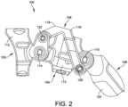
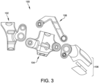
- FIGS. 1-3 illustrate perspective, side, and exploded views of one embodiment of a prosthetic finger 100.
- prosthetic finger 100 may include four major interconnected components that extend from a proximal end located at the patient's hand to a distal end located at a distance from the patient's hand. These components include a proximal ring 102, a distal ring 104, a coupling tip 106, and an H-shaped rocker 108.
- Proximal ring 102 and distal ring 104 may each have a respective body 112, 113.
- bodies 112, 113 may form circular or ring shapes that are configured to anchor onto a patient's/user's residual finger.
- body 112 of proximal ring 102 may be configured to anchor about a proximal phalanx of a user's residual finger with a snug fit.
- body 113 of distal ring 104 may be configured to anchor about a middle phalanx of a user's residual finger with a snug fit.
- FIG. 4 depicts a centerline, C, that bisects prosthetic finger 100 relative to a y-axis
- FIG. 5 shows a midline, M, that intersects a first hinged connection 110 and a second hinged connection 114, both detailed below, relative to a z-axis.
- distal ring 104 may rotatively couple with coupling tip 106 via first hinged connection 110.
- First hinged connection 110 may include a pair of parallel pivotal hinges that are symmetric about centerline, C, discussed above in relation to FIG. 4 .
- Each of the pivotal hinges of connection 110 may provide a pivot point between distal ring 104 and coupling tip 106.
- Proximal ring 102 may rotatively couple with distal ring 104 via second hinged connection 114.
- Second hinged connection 114 may also include a pair of parallel pivotal hinges that are symmetric about the centerline, C, one located on each side of prosthetic finger 100 such that each provides a pivot point between proximal ring 102 and distal ring 104.
- the midline, M intersects hinged connections 110 and 114, and, therefore, both first and second hinged connections 110, 114 are located directly upon the midline, M, relative to the z-axis.
- Rocker 108 may form a H-shape having opposing first and second ends 116, 118, respectively, that extend between coupling tip 106 and proximal ring 102.
- First end 116 may form a first split prong of the H-shape and rotatively couple with coupling tip 106 via a third hinged connection 120 ( FIGS. 1-2 ) located below the midline, M, relative to the z-axis.
- Second end 118 may form a second split prong of the H-shape and rotatively couple with proximal ring 102 via a fourth hinged connection 122 ( FIGS. 1-2 ) located above the midline, M, relative to the z-axis.
- Both third and fourth hinged connections 120, 122 may include a pair of parallel pivotal hinges that are symmetric about the centerline, C, each providing a pivot point between rocker 108 and coupling tip 106/proximal ring 102.
- first, second, third, and/or fourth hinged connections 110, 114, 120, 122 may be outfitted with hard-stops to prevent hyperextension of finger 100 during operation.
- a hard-stop 127 shown in FIG. 1 , may prevent relative over-rotation of first hinged connection 110, or between distal ring 104 and coupling tip 106.
- Mechanical hard-stops may have any appropriate size, shape, and/or configuration.
- proximal ring 102, distal ring 104, coupling tip 106, and H-shaped rocker 108 form a 4-bar linkage system that allows the coupling tip to be articulated in response to a pulling force on distal ring 104, which places the member in tension and reduces the risk of buckling.
- distal ring 104 which places the member in tension and reduces the risk of buckling.
- natural movement of the patient's residual finger seated within proximal ring 102 and distal ring 104, or in some cases movement of his or her adjacent fingers may be used to actuate realistic flexion and extension motions within prosthetic finger 100. Users may perform their full range of usual activities, including typing, playing a musical instrument, or any other activity that requires the full dexterity of the hand.
- rocker 108 allows third hinged connection 120 between rocker 108 and coupling tip 106 to occur outside the assembly, or outside the physical boundary defined by distal ring 104 and coupling tip 106.
- This configuration allows users with a relatively longer residual finger, or a relatively long middle phalanx, to take advantage of additional clearance space within the assembly.
- the residual finger may fit comfortably within the assembly, while still being protected against further damage and/or hypersensitivity. That said, while rocker 108 is described herein as having an H-shaped profile, it should be understood that rocker 108 may take any appropriate size, shape, type, and/or configuration.
- coupling tip 106 may include a tip pad 124.
- Tip pad 124 may be formed from a soft-textured silicone or other material that mimics the texture of a real finger. This aids with gripping and provides a softer touch.
- a touchscreen mechanism (not shown) may be provided to allow the user to use the prosthetic finger to operate capacitive touchscreens, which react to the body's natural current. The touchscreen mechanism allows the user to direct his or her own body current through the tip of the prosthetic finger.
- coupling tip 106 may also include a nail 126, which mimics a natural edged nail that may provide scratching and peeling functionalities as well as assist with fine-object manipulation.
- Embodiments of prosthetic finger 100 are custom designed and individually fitted to accommodate a variety of differing user conditions, including different residual-finger lengths (e.g., varying amounts of loss to the finger).
- each finger 100 may be customized to fit a particular patient or user, providing both custom functionality as well as a mechanical match to the anatomical joint articulation of the user, including matching the length of the original, non-amputated finger.
- Design considerations include an amount of finger loss, a number of joints to be replaced, and other characteristics specific to the individual end user.
- H-shaped rocker 108 is designed to provide a full-coverage "cage" above and about a patient's residual finger, thereby protecting the residual finger from irritation and/or hypersensitivity, without interfering with the residual finger within the prosthetic finger device 100.
- a user Outfitted with H-shaped rocker 108, a user may anchor any length of prosthetic finger within finger 100, even if the residual finger length extends well past the proximal interphalangeal ("PIP") joint.
- PIP proximal interphalangeal
- coupling tip 106 may be removed so that prosthetic finger 100 functions as a joint brace, rather than a digit replacement.
- embodiments of finger 100 may be coated with films and/or colorings matched to the user's skin tone/color.
- An additive manufacturing process i.e., 3D printing
- 3D printing facilitates this ability to customize the intricacies of the prosthetic finger design in order to optimize prosthetic finger 100 for each patient.
- Embodiments of prosthetic finger 100 may be formed of any suitable structural material that is non-irritating to human skin and allows the user to operate the prosthetic with comfort and confidence.
- Exemplary materials include titanium, stainless steel, aluminum, silicone, carbon fiber, nylon, plastic/polymer, wood, rubber, gold, silver, tungsten, flex cable, neoprene, or any other suitable material.
- components of prosthetic finger 100 are 3D printed from Duraform EX polymer material.
- various embodiments of finger 100 may be applied as an orthopedic implant that may be surgically implanted into a user's finger. This option may be applied for users having injuries that have crushed their finger bones without the ability to heal or be repaired. In these situations, implantable embodiments of prosthetic finger 100 are able to take the place of the user's original bones without the need for amputation.
- FIG. 6 depicts a rear view of prosthetic finger 100, in which body 112 of proximal ring 102 is outfitted with a semi-circular shim 128, which is employed to allow the sizing of body 112 to account for possible swelling in the fingers, weight gain/loss, or any other post-manufacture changes in the size of the residual finger.
- a fit kit (not shown) may be provided with each prosthetic finger 100 and may include a number of shims 128.
- each shim 128 may approximate a semi-circle or U-shape configured to abut an inner diameter, d, of body 112 of proximal ring 102 and may have a number of retaining grommets 130 configured to protrude through corresponding shim-retainment apertures 132 within body 112.
- Each shim 128 may have a different thickness, t, thereby allowing the user to essentially adjust the inner diameter, d, of body 112 of proximal ring 102 in a number of increments as required by the user.
- prosthetic finger 100 (adjusted or otherwise) is in place, the user can utilize his or her natural movements of the residual finger.
- the primary components of prosthetic finger 100 will articulate using the same cognitive process that was previously utilized for the original finger. If a user wears multiple fingers 100, each may be individually operated.
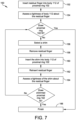
- FIG. 7 provides a flow chart depicting an exemplary method 150 for installing and adjusting, or fitting, one embodiment of prosthetic finger 100 upon a user's residual finger.
- the method begins with inserting (152) the residual finger into body 112 of proximal ring 102 and assessing a tightness (154) of body 112 about the residual finger.
- a medical professional, or another assistant selects a first shim 128 (156) from the fit kit or another source.
- first shim 128 160
- first shim 128 160
- the user reinserts the residual finger (162) into proximal ring 102 and assess a tightness (164) of first shim 128 (which now lines body 112 of proximal ring 102) about the residual finger. If the shimmed proximal ring 102 fits, method 150 is complete (166), and the user may proceed to biomechanically drive prosthetic finger 100.
- method 150 may return to the step of selecting a shim (156), in which a second shim having a different thickness may be selected before proceeding.
- a shim 156
- the user may experiment with multiple shims of varying thicknesses until an ideal or desired fit is achieved.
- distal ring 104 may be adjusted in a manner similar to that discussed with respect to proximal ring 102 and method 150.
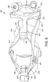
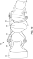
- FIGS. 8-11 illustrate first perspective, top, bottom, and second perspective views of an alternate embodiment of a prosthetic finger 200.
- prosthetic finger 200 includes three primary interlinked components: a rocker 202 having a proximal end 204 and a distal end 206, a proximal linkage 208, and a distal linkage 210.
- distal linkage 210 rotatively couples with proximal linkage 208, which may, in turn, couple with proximal end 204 of rocker 202.
- Distal end 206 of rocker 202 may rotatively couple with a swiveling tip brace 211.
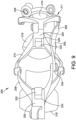
- Swiveling tip brace 211 may feature a tip fastener joint 226, shown in FIGS. 8-9 and 11 , that allows a receiving tip 212 to be positioned at varying angles relative to swiveling tip brace 211 and to the remainder of prosthetic finger 200 in order to achieve different grip strengths and/or articulation characteristics.
- a tip pad 214 may attach to tip 212 in any appropriate manner.
- Two cage rings attach to the linkages for the purpose of retaining a user's residual finger (with one ring proximal of the proximal interphalangeal ("PIP") joint and another ring distal of the PIP joint) and translating movement of the residual finger through the interlinked assembly discussed above.
- a proximal cage ring 216 and a distal cage ring 218 attach to proximal linkage 208 and distal linkage 210, respectively.
- This attachment may be facilitated by a universal ring mount 220 located on each of proximal linkage 208 and distal linkage 210.
- Each universal ring mount 220 may define a ring mount aperture 224 that is configured to receive an attachment protrusion 222 of each of cage rings 216, 218.
- a user/patient may slide proximal and distal cage rings 216, 218 of prosthetic finger 200 over his or her residual finger like a ring.
- Each finger 200 may be customized to fit the particular user in question.
- rocker 202, proximal and distal linkages 208, 210, and/or swiveling tip brace 211 may be customized to accommodate the length of the user's residual finger or other physical characteristic of the particular user, such that when prosthetic finger 200 is anchored to the user's residual finger, an end or tip of the residual finger nests within or adjacent to receiving tip 212.
- receiving tip 212 may be curved or "cupped" to receive the residual finger end or tip in a manner that protects the user's finger from further damage and/or hypersensitivity.
- the components of prosthetic finger 200 not only look realistic during articulation, but receiving tip 212, with a residual finger end or tip nested therein, bends in a realistic manner as rocker 202 is articulated.
- prosthetic finger 200 may be custom designed to custom fit each user, post-manufacturing changes to the patient's physiology may occur.
- both proximal cage ring 216 and distal cage ring 218 may be interchangeable such that they may be swapped out with rings of varying sizes to address sizing and/or swelling fluctuations demonstrated in the residual finger of the patient. Varying sizes of proximal and distal cage rings 216, 218 may be provided in a fit kit (not shown), allowing the user to employ the most appropriate ring sizes in real-time.
- Interchangeable rings 216, 218 may be formed of any appropriate material including flexible polymers or other plastics that are non-irritating to human skin.
- Embodiments of the prosthetic fingers 100, 200 described above exhibit numerous unique characteristics and provide a variety of medical benefits.
- An individual's unique physiology and lifestyle patterns dictate the function and performance expected of his or her hands.
- patients may regain independent control of their hands, whether at work or at play.
- Each device is custom designed, manufactured for a specific individual, and incorporates features that allow for further fine-tuning and adjustment of fit to account for post-manufacturing fluctuations (e.g., shims and or interchangeable rings), enabling the device to fit the user in a manner that allows for a biomechanically driven, low profile, lightweight, highly functioning return to the user's everyday activities, no matter what those activities might entail.
- a few examples include typing, playing the piano or another instrument, woodworking, and much more.
- Embodiments of the prosthetic fingers described above are body powered, and their linked components articulate when the user simply moves his or her residual finger, when available, or an adjacent finger when necessary. Beyond allowing for a simple, elegant, and streamlined design that offers strength in the lowest possible profile design, employing the user's own biomechanics to drive embodiments of prosthetic fingers 100, 200 provides a host of medical benefits to the user, including reduced swelling of and increased circulation to the residual finger and the hand as a whole, supporting healthy joints in the injured and adjacent fingers.
Landscapes
- Health & Medical Sciences (AREA)
- Transplantation (AREA)
- Engineering & Computer Science (AREA)
- Life Sciences & Earth Sciences (AREA)
- Oral & Maxillofacial Surgery (AREA)
- Biomedical Technology (AREA)
- Heart & Thoracic Surgery (AREA)
- Vascular Medicine (AREA)
- Cardiology (AREA)
- Animal Behavior & Ethology (AREA)
- General Health & Medical Sciences (AREA)
- Public Health (AREA)
- Veterinary Medicine (AREA)
- Orthopedic Medicine & Surgery (AREA)
- Manufacturing & Machinery (AREA)
- Prostheses (AREA)
Description
- If a person loses a finger, a finger segment, or a fingertip, the result is impaired performance of the hand. Having an amputated finger inhibits an amputee from performing some of the most basic tasks. For example, with a lost finger or fingertip, the task of typing on a computer keyboard or dialing on a telephone becomes significantly more difficult. These types of tasks require precise actions that only fingers are able to offer.
- Not only do they allow for the performance of precise physical actions, fingers also provide an increased ability to grip or handle items. While holding an item in the hand, the weight of the item is dispersed through all of a user's fingers. By varying the force used by each finger on the holder's hand, the holder is able to manipulate the item in a myriad of ways. However, if the holder is missing all or even part of a single digit, or if a digit is present but nonfunctioning, this freedom of manipulation and the number of degrees through which the holder can manipulate the item is drastically decreased.
- Current prosthetic finger solutions demonstrate several drawbacks. First, a primary category of prosthetic fingers offers only cosmetic restoration. These prosthetics are designed to be worn passively and offer a realistic look. They provide little to no functionality and do not enable the owner to restore functionality to his or her hand. Other prosthetics offer the user some level of restored functionality, but are complex in design and electrically powered. These prosthetics, while perhaps better than going without, are impractical in that they require an external power source and can be both bulky and unwieldy for the user to manage. Still other prosthetic fingers are body-powered but lack the design flexibility necessary to accommodate any length of residual finger (e.g., all or partially amputated and varying degrees of amputation) while providing maximum dexterity, grip strength, and finger articulation.
US2014/0303749 discloses a prosthetic full finger assembly.US2012/0330432 discloses a finger prosthesis.US2005/0043822 discloses an articulated artificial finger assembly. - This Summary is provided to introduce a selection of concepts in a simplified form that are further described below in the Detailed Description. This Summary is not intended to identify key aspects or essential aspects of the claimed subject matter. Moreover, this Summary is not intended for use as an aid in determining the scope of the claimed subject matter.
- The present invention provides a method of fitting a customized prosthetic finger having a proximal ring configured to anchor to a patient's residual finger, where the proximal ring contains one or more shim-retainment apertures. The method begins with inserting the residual finger into an interior of the proximal ring of the prosthetic finger and continues with assessing a tightness of the proximal ring about the residual finger. Next, the method includes selecting a first shim having a first thickness from a plurality of shims configured to line the interior of the proximal ring, each of the shims including one or more retaining grommets, and removing the residual finger from the proximal ring. Then the method involves inserting the first shim into the interior of the proximal ring such that the retaining grommets protrude through the shim-retainment apertures, thereby retaining the first shim within the interior of the proximal ring, before reinserting the residual finger.
- The method discussed above may further include assessing a tightness of the first shim about the residual finger, and then removing the residual finger and the first shim before selecting, from the plurality of shims, a second shim having a second thickness. Once the second shim is selected, the user may continue by inserting the second shim into the interior of the proximal ring such that the retaining grommets protrude through the shim-retainment apertures, thereby retaining the second shim within the interior of the proximal ring.
- Additional objects, advantages and novel features of the technology will be set forth in part in the description which follows, and in part will become more apparent to those skilled in the art upon examination of the following, or may be learned from practice of the technology.
- Non-limiting and non-exhaustive embodiments of the present invention, including the preferred embodiment, are described with reference to the following figures, wherein like reference numerals refer to like parts throughout the various views unless otherwise specified. Illustrative embodiments of the invention are illustrated in the drawings, in which:
-
FIGURE 1 illustrates a perspective view of one embodiment of a prosthetic finger assembly featuring an H-shaped rocker; -
FIGURE 2 illustrates a left-side elevation view of the prosthetic finger assembly ofFIGURE 1 ; -
FIGURE 3 illustrates an exploded view of the prosthetic finger assembly ofFIGURES 1 and2 ; -
FIGURE 4 illustrates a top view of the prosthetic finger assembly ofFIGURES 1-3 , with a centerline axis bisecting the assembly relative to a y-axis; -
FIGURE 5 illustrates another left-side view of the prosthetic finger assembly ofFIGURES 1-4 , with a midline axis intersecting first and second hinged connections relative to a z-axis; -
FIGURE 6 illustrates an end view of the prosthetic finger assembly ofFIGURES 1-5 with an inserted shim; -
FIGURE 7 illustrates a flow chart depicting an exemplary method of fitting the prosthetic finger assembly ofFIGURES 1-6 ; -
FIGURE 8 illustrates a perspective view of one embodiment of a prosthetic finger device having a single rocker connecting a cupped receiving tip with a distal linkage and a proximal linkage; -
FIGURE 9 illustrates a top view of the prosthetic finger device ofFIGURE 6 ; -
FIGURE 10 illustrates a bottom view of the prosthetic finger device ofFIGURES 8-9 ; and -
FIGURE 11 illustrates another perspective view of the prosthetic finger device ofFIGURES 8-10 with the cupped receiving tip in an extended position. - Embodiments are described more fully below in sufficient detail to enable those skilled in the art to practice the system and method. However, embodiments may be implemented in many different forms and should not be construed as being limited to the embodiments set forth herein. The following detailed description is, therefore, not to be taken in a limiting sense.
- Various embodiments disclosed herein relate to a custom-designed, self-contained prosthetic finger, to be used with the method of the invention, that can be fitted for a user with an amputated finger, fingertip, or finger segment. The streamlined, sophisticated, and biomechanically driven design allows for a patient with any level of residual finger to utilize a mechanical replacement that mimics the motions and functionalities of a real finger. The natural action of the prosthetic finger assembly allows users to regain maximum control of the flexion and extension movements of a full finger and fingertip and is designed to bend and curl in a realistic, natural manner in response to movement in the user's residual finger or adjacent fingers.
- Embodiments described herein feature specially designed components, such as an H-shaped rocker and/or a cupped receiving tip, both discussed in detail below, that allow the prosthetic finger to anchor to any length of residual finger, while protecting the amputation site against further injury or hypersensitivity and providing the individual user with maximum fit and use flexibility, dexterity, grip strength, and articulation. As a result, the prosthetic finger offers digit amputees a functional solution that eases the transition back into daily activities, no matter how intricate, after amputation.
-
FIGS. 1-3 illustrate perspective, side, and exploded views of one embodiment of aprosthetic finger 100. In this embodiment,prosthetic finger 100 may include four major interconnected components that extend from a proximal end located at the patient's hand to a distal end located at a distance from the patient's hand. These components include aproximal ring 102, adistal ring 104, acoupling tip 106, and an H-shaped rocker 108.Proximal ring 102 anddistal ring 104 may each have arespective body bodies body 112 ofproximal ring 102 may be configured to anchor about a proximal phalanx of a user's residual finger with a snug fit. Similarly,body 113 ofdistal ring 104 may be configured to anchor about a middle phalanx of a user's residual finger with a snug fit. - A series of hinges may be used to secure the four primary components discussed above via rotative connections. In one embodiment, these rotative connections may be particularly positioned with respect to a pair of axes detailed in
FIGS. 4-5 . More specifically,FIG. 4 depicts a centerline, C, that bisectsprosthetic finger 100 relative to a y-axis, andFIG. 5 shows a midline, M, that intersects a first hingedconnection 110 and a second hingedconnection 114, both detailed below, relative to a z-axis. - Turning to the various rotative connections shown in
FIGS. 1-2 ,distal ring 104 may rotatively couple withcoupling tip 106 via first hingedconnection 110. First hingedconnection 110 may include a pair of parallel pivotal hinges that are symmetric about centerline, C, discussed above in relation toFIG. 4 . Each of the pivotal hinges ofconnection 110 may provide a pivot point betweendistal ring 104 andcoupling tip 106. -
Proximal ring 102 may rotatively couple withdistal ring 104 via second hingedconnection 114. Second hingedconnection 114 may also include a pair of parallel pivotal hinges that are symmetric about the centerline, C, one located on each side ofprosthetic finger 100 such that each provides a pivot point betweenproximal ring 102 anddistal ring 104. As discussed above in relation toFIG. 5 , the midline, M, intersects hingedconnections connections -
Rocker 108 may form a H-shape having opposing first and second ends 116, 118, respectively, that extend betweencoupling tip 106 andproximal ring 102.First end 116 may form a first split prong of the H-shape and rotatively couple withcoupling tip 106 via a third hinged connection 120 (FIGS. 1-2 ) located below the midline, M, relative to the z-axis.Second end 118 may form a second split prong of the H-shape and rotatively couple withproximal ring 102 via a fourth hinged connection 122 (FIGS. 1-2 ) located above the midline, M, relative to the z-axis. Both third and fourth hingedconnections rocker 108 andcoupling tip 106/proximal ring 102. - Any one or more of the first, second, third, and/or fourth hinged
connections finger 100 during operation. For example, a hard-stop 127, shown inFIG. 1 , may prevent relative over-rotation of first hingedconnection 110, or betweendistal ring 104 andcoupling tip 106. Mechanical hard-stops may have any appropriate size, shape, and/or configuration. - Working together,
proximal ring 102,distal ring 104,coupling tip 106, and H-shapedrocker 108 form a 4-bar linkage system that allows the coupling tip to be articulated in response to a pulling force ondistal ring 104, which places the member in tension and reduces the risk of buckling. Thus, natural movement of the patient's residual finger seated withinproximal ring 102 anddistal ring 104, or in some cases movement of his or her adjacent fingers, may be used to actuate realistic flexion and extension motions withinprosthetic finger 100. Users may perform their full range of usual activities, including typing, playing a musical instrument, or any other activity that requires the full dexterity of the hand. - The H-shape of
rocker 108 allows third hingedconnection 120 betweenrocker 108 andcoupling tip 106 to occur outside the assembly, or outside the physical boundary defined bydistal ring 104 andcoupling tip 106. This configuration allows users with a relatively longer residual finger, or a relatively long middle phalanx, to take advantage of additional clearance space within the assembly. The residual finger may fit comfortably within the assembly, while still being protected against further damage and/or hypersensitivity. That said, whilerocker 108 is described herein as having an H-shaped profile, it should be understood thatrocker 108 may take any appropriate size, shape, type, and/or configuration. - In the embodiment shown in
FIGS. 1-5 ,coupling tip 106 may include atip pad 124.Tip pad 124 may be formed from a soft-textured silicone or other material that mimics the texture of a real finger. This aids with gripping and provides a softer touch. In one embodiment, a touchscreen mechanism (not shown) may be provided to allow the user to use the prosthetic finger to operate capacitive touchscreens, which react to the body's natural current. The touchscreen mechanism allows the user to direct his or her own body current through the tip of the prosthetic finger. - One embodiment of
coupling tip 106 may also include a nail 126, which mimics a natural edged nail that may provide scratching and peeling functionalities as well as assist with fine-object manipulation. - Embodiments of
prosthetic finger 100 are custom designed and individually fitted to accommodate a variety of differing user conditions, including different residual-finger lengths (e.g., varying amounts of loss to the finger). In this regard, eachfinger 100 may be customized to fit a particular patient or user, providing both custom functionality as well as a mechanical match to the anatomical joint articulation of the user, including matching the length of the original, non-amputated finger. Design considerations include an amount of finger loss, a number of joints to be replaced, and other characteristics specific to the individual end user. H-shapedrocker 108 is designed to provide a full-coverage "cage" above and about a patient's residual finger, thereby protecting the residual finger from irritation and/or hypersensitivity, without interfering with the residual finger within theprosthetic finger device 100. Outfitted with H-shapedrocker 108, a user may anchor any length of prosthetic finger withinfinger 100, even if the residual finger length extends well past the proximal interphalangeal ("PIP") joint. In cases in which the user has a fully formed, but poorly or nonfunctioning finger,coupling tip 106 may be removed so thatprosthetic finger 100 functions as a joint brace, rather than a digit replacement. - To further provide better aesthetics, embodiments of
finger 100 may be coated with films and/or colorings matched to the user's skin tone/color. An additive manufacturing process (i.e., 3D printing) facilitates this ability to customize the intricacies of the prosthetic finger design in order to optimizeprosthetic finger 100 for each patient. - Embodiments of
prosthetic finger 100 may be formed of any suitable structural material that is non-irritating to human skin and allows the user to operate the prosthetic with comfort and confidence. Exemplary materials include titanium, stainless steel, aluminum, silicone, carbon fiber, nylon, plastic/polymer, wood, rubber, gold, silver, tungsten, flex cable, neoprene, or any other suitable material. In one embodiment, components ofprosthetic finger 100 are 3D printed from Duraform EX polymer material. - Using biocompatible materials, various embodiments of
finger 100 may be applied as an orthopedic implant that may be surgically implanted into a user's finger. This option may be applied for users having injuries that have crushed their finger bones without the ability to heal or be repaired. In these situations, implantable embodiments ofprosthetic finger 100 are able to take the place of the user's original bones without the need for amputation. - To use, the user may simply slide
proximal ring 102 anddistal ring 104 onto his or her residual finger, and, if necessary, adjust further using a shim(s).FIG. 6 depicts a rear view ofprosthetic finger 100, in whichbody 112 ofproximal ring 102 is outfitted with asemi-circular shim 128, which is employed to allow the sizing ofbody 112 to account for possible swelling in the fingers, weight gain/loss, or any other post-manufacture changes in the size of the residual finger. In further detail, a fit kit (not shown) may be provided with eachprosthetic finger 100 and may include a number ofshims 128. In one embodiment, eachshim 128 may approximate a semi-circle or U-shape configured to abut an inner diameter, d, ofbody 112 ofproximal ring 102 and may have a number of retaininggrommets 130 configured to protrude through corresponding shim-retainment apertures 132 withinbody 112. Eachshim 128 may have a different thickness, t, thereby allowing the user to essentially adjust the inner diameter, d, ofbody 112 ofproximal ring 102 in a number of increments as required by the user. - Once prosthetic finger 100 (adjusted or otherwise) is in place, the user can utilize his or her natural movements of the residual finger. The primary components of
prosthetic finger 100 will articulate using the same cognitive process that was previously utilized for the original finger. If a user wearsmultiple fingers 100, each may be individually operated. -
FIG. 7 provides a flow chart depicting anexemplary method 150 for installing and adjusting, or fitting, one embodiment ofprosthetic finger 100 upon a user's residual finger. The method begins with inserting (152) the residual finger intobody 112 ofproximal ring 102 and assessing a tightness (154) ofbody 112 about the residual finger. Depending on this assessment (154), the user, a medical professional, or another assistant selects a first shim 128 (156) from the fit kit or another source. The user then removes the residual finger (158) fromproximal ring 102 and insert first shim 128 (160) into the inner diameter, d, ofbody 112 such thatfirst shim 128 lines the inner diameter, d, while retaininggrommets 130 protrude through shim-retainment apertures 132. Once first shim is installed (160), the user reinserts the residual finger (162) intoproximal ring 102 and assess a tightness (164) of first shim 128 (which now linesbody 112 of proximal ring 102) about the residual finger. If the shimmedproximal ring 102 fits,method 150 is complete (166), and the user may proceed to biomechanically driveprosthetic finger 100. If shimmedproximal ring 102 does not fit,method 150 may return to the step of selecting a shim (156), in which a second shim having a different thickness may be selected before proceeding. The user may experiment with multiple shims of varying thicknesses until an ideal or desired fit is achieved. Of course,distal ring 104 may be adjusted in a manner similar to that discussed with respect toproximal ring 102 andmethod 150. -
FIGS. 8-11 illustrate first perspective, top, bottom, and second perspective views of an alternate embodiment of aprosthetic finger 200. In this embodiment,prosthetic finger 200 includes three primary interlinked components: arocker 202 having aproximal end 204 and adistal end 206, aproximal linkage 208, and adistal linkage 210. In further detail, and as shown inFIGS. 8-9 ,distal linkage 210 rotatively couples withproximal linkage 208, which may, in turn, couple withproximal end 204 ofrocker 202.Distal end 206 ofrocker 202 may rotatively couple with a swivelingtip brace 211. Swivelingtip brace 211 may feature a tip fastener joint 226, shown inFIGS. 8-9 and11 , that allows a receivingtip 212 to be positioned at varying angles relative to swivelingtip brace 211 and to the remainder ofprosthetic finger 200 in order to achieve different grip strengths and/or articulation characteristics. Atip pad 214 may attach to tip 212 in any appropriate manner. - Two cage rings attach to the linkages for the purpose of retaining a user's residual finger (with one ring proximal of the proximal interphalangeal ("PIP") joint and another ring distal of the PIP joint) and translating movement of the residual finger through the interlinked assembly discussed above. As shown in
FIGS. 6-9 , aproximal cage ring 216 and adistal cage ring 218 attach toproximal linkage 208 anddistal linkage 210, respectively. This attachment may be facilitated by auniversal ring mount 220 located on each ofproximal linkage 208 anddistal linkage 210. Eachuniversal ring mount 220 may define aring mount aperture 224 that is configured to receive anattachment protrusion 222 of each of cage rings 216, 218. - In use, a user/patient may slide proximal and distal cage rings 216, 218 of
prosthetic finger 200 over his or her residual finger like a ring. Eachfinger 200 may be customized to fit the particular user in question. As a result,rocker 202, proximal anddistal linkages tip brace 211 may be customized to accommodate the length of the user's residual finger or other physical characteristic of the particular user, such that whenprosthetic finger 200 is anchored to the user's residual finger, an end or tip of the residual finger nests within or adjacent to receivingtip 212. In one embodiment, receivingtip 212 may be curved or "cupped" to receive the residual finger end or tip in a manner that protects the user's finger from further damage and/or hypersensitivity. The components ofprosthetic finger 200 not only look realistic during articulation, but receivingtip 212, with a residual finger end or tip nested therein, bends in a realistic manner asrocker 202 is articulated. - While
prosthetic finger 200 may be custom designed to custom fit each user, post-manufacturing changes to the patient's physiology may occur. To add post-manufacturing customization capabilities toprosthetic finger 200, bothproximal cage ring 216 anddistal cage ring 218 may be interchangeable such that they may be swapped out with rings of varying sizes to address sizing and/or swelling fluctuations demonstrated in the residual finger of the patient. Varying sizes of proximal and distal cage rings 216, 218 may be provided in a fit kit (not shown), allowing the user to employ the most appropriate ring sizes in real-time. The user may easily interchange cage rings by removing therings ring mount apertures 224 andattachment protrusions 222.Interchangeable rings - Embodiments of the
prosthetic fingers - Embodiments of the prosthetic fingers described above are body powered, and their linked components articulate when the user simply moves his or her residual finger, when available, or an adjacent finger when necessary. Beyond allowing for a simple, elegant, and streamlined design that offers strength in the lowest possible profile design, employing the user's own biomechanics to drive embodiments of
prosthetic fingers - Although the above embodiments have been described in language that is specific to certain structures, elements, compositions, and methodological steps, it is to be understood that the technology defined in the appended claims is not necessarily limited to the specific structures, elements, compositions and/or steps described. Rather, the specific aspects and steps are described as forms of implementing the claimed technology. Since many embodiments of the technology can be practiced without departing from the scope of the invention, the invention resides in the claims hereinafter appended.
Claims (4)
- A method of fitting a customized prosthetic finger (100) having a proximal ring (102) configured to anchor to a patient's residual finger, comprising:inserting the residual finger into an interior of the proximal ring (102) of the prosthetic finger (100);assessing a tightness of the proximal ring (102) about the residual finger;selecting a first shim (128) having a first thickness from a plurality of shims configured to line the interior of the proximal ring (102);removing the prosthetic finger (100);inserting the first shim (128) into the interior of the proximal ring (102); andreinserting the residual finger; characterised in thatthe proximal ring (102) contains one or more shim-retainment apertures (132),each of the shims include one or more retaining grommets (130), andthe first shim (128) is retained onto the interior of the proximal ring (102) by the retaining grommets (130) configured to protrude through the shim-retainment apertures (132).
- The method of claim 1, further comprising:assessing a tightness of the first shim (128) about the residual finger;removing the prosthetic finger (100);removing the first shim (128);selecting, from the plurality of shims, a second shim having a second thickness; andinserting the second shim into the interior of the proximal ring (102) such that the retaining grommets (130) protrude through the shim-retainment apertures (132), thereby retaining the second shim within the interior of the proximal ring.
- The method of claim 1, wherein each of the plurality of shims has a different thickness.
- The method of claim 1, wherein each of the plurality of shims has a shape that approximates a U-shape.
Applications Claiming Priority (4)
| Application Number | Priority Date | Filing Date | Title |
|---|---|---|---|
| US201562111464P | 2015-02-03 | 2015-02-03 | |
| US201562209843P | 2015-08-25 | 2015-08-25 | |
| EP16747133.3A EP3244840B1 (en) | 2015-02-03 | 2016-02-02 | Bio-mechanical prosthetic finger with h-shaped rocker |
| PCT/US2016/016219 WO2016126736A1 (en) | 2015-02-03 | 2016-02-02 | Bio-mechanical prosthetic finger with h-shaped rocker |
Related Parent Applications (2)
| Application Number | Title | Priority Date | Filing Date |
|---|---|---|---|
| EP16747133.3A Division EP3244840B1 (en) | 2015-02-03 | 2016-02-02 | Bio-mechanical prosthetic finger with h-shaped rocker |
| EP16747133.3A Division-Into EP3244840B1 (en) | 2015-02-03 | 2016-02-02 | Bio-mechanical prosthetic finger with h-shaped rocker |
Publications (3)
| Publication Number | Publication Date |
|---|---|
| EP3735942A2 EP3735942A2 (en) | 2020-11-11 |
| EP3735942A3 EP3735942A3 (en) | 2021-01-27 |
| EP3735942B1 true EP3735942B1 (en) | 2024-06-19 |
Family
ID=56564610
Family Applications (2)
| Application Number | Title | Priority Date | Filing Date |
|---|---|---|---|
| EP19198445.9A Active EP3735942B1 (en) | 2015-02-03 | 2016-02-02 | Bio-mechanical prosthetic finger with h-shaped rocker |
| EP16747133.3A Active EP3244840B1 (en) | 2015-02-03 | 2016-02-02 | Bio-mechanical prosthetic finger with h-shaped rocker |
Family Applications After (1)
| Application Number | Title | Priority Date | Filing Date |
|---|---|---|---|
| EP16747133.3A Active EP3244840B1 (en) | 2015-02-03 | 2016-02-02 | Bio-mechanical prosthetic finger with h-shaped rocker |
Country Status (6)
| Country | Link |
|---|---|
| US (4) | US9707102B2 (en) |
| EP (2) | EP3735942B1 (en) |
| JP (4) | JP6637071B2 (en) |
| AU (3) | AU2016215443B2 (en) |
| CA (2) | CA3158806A1 (en) |
| WO (1) | WO2016126736A1 (en) |
Families Citing this family (16)
| Publication number | Priority date | Publication date | Assignee | Title |
|---|---|---|---|---|
| US9707101B2 (en) | 2015-02-03 | 2017-07-18 | Rcm Enterprise Llc | Bio-mechanical prosthetic finger with Y-shaped rocker |
| WO2016126739A1 (en) | 2015-02-03 | 2016-08-11 | RCM Enterprise, LLC | Biomechanical finger brace assembly |
| JP6637071B2 (en) | 2015-02-03 | 2020-01-29 | アールシーエム エンタープライズ, エルエルシーRcm Enterprise, Llc | Biomechanical artificial finger with H-shaped rocker |
| WO2016187127A1 (en) | 2015-05-15 | 2016-11-24 | RCM Enterprise, LLC | Bidirectional biomechanical prosthetic full finger configured for abduction and adduction with mcp pivot |
| WO2016187133A1 (en) | 2015-05-15 | 2016-11-24 | RCM Enterprise, LLC | Bidirectional biomechanical prosthetic full finger configured for abduction and adduction with mcp pivot and multiple-finger ring |
| US10235129B1 (en) | 2015-06-29 | 2019-03-19 | Amazon Technologies, Inc. | Joining users to communications via voice commands |
| US10905570B2 (en) | 2018-11-19 | 2021-02-02 | The Regents Of The University Of Colorado, A Body Corporate | Prosthetic partial fingers |
| US10744006B2 (en) * | 2019-01-15 | 2020-08-18 | Sai Vipparla | Pet prosthetic |
| EP4102688A4 (en) | 2020-03-19 | 2024-02-28 | Meidensha Corporation | ELECTRIC MACHINE AND MOTOR |
| CN112690940B (en) * | 2020-12-23 | 2022-10-11 | 黑龙江中医药大学 | Prevent and delay finger joint deformity corrector |
| EP4431064A3 (en) | 2021-02-10 | 2024-12-11 | Point Designs LLC | Prosthetic thumb device |
| MX2021013325A (en) * | 2021-10-29 | 2023-05-01 | Paola Aralid Izaguirre Perez | Exoskeleton-type system for orthosis and prosthesis of hand phalanges. |
| KR102626907B1 (en) * | 2021-12-15 | 2024-01-17 | 한남대학교 산학협력단 | The functional finger prosthetic |
| KR102700762B1 (en) * | 2022-02-11 | 2024-08-29 | 신성대학교 산학협력단 | Finger assistance apparatus |
| DE102023002140A1 (en) | 2023-05-15 | 2024-11-21 | Daniel Lang | Distal finger prosthesis module for a modular finger prosthesis |
| WO2025143328A1 (en) * | 2023-12-28 | 2025-07-03 | 최혜란 | Non-powered finger prosthethis |
Family Cites Families (58)
| Publication number | Priority date | Publication date | Assignee | Title |
|---|---|---|---|---|
| US319776A (en) | 1885-06-09 | Tebeitoby | ||
| US984179A (en) | 1910-09-26 | 1911-02-14 | Leonard Aydt | Artificial hand. |
| GB108872A (en) | 1916-11-20 | 1917-08-30 | Enos Robinson | Improvements in or relating to Artificial Hands. |
| GB110333A (en) | 1917-07-24 | 1917-10-18 | Heinrich Troendle | Improved Padding for Artificial Hands. |
| US2598593A (en) * | 1948-09-30 | 1952-05-27 | Ibm | Polycentric articulated finger for artificial hands |
| US2706296A (en) | 1953-05-26 | 1955-04-19 | Maurice J Fletcher | Prosthetic appliance |
| US2867819A (en) | 1954-05-07 | 1959-01-13 | Lloyd E George | Artificial fingers |
| US2876819A (en) | 1955-08-11 | 1959-03-10 | Aristocrat Leather Products In | Combination billfold and purse |
| US3483718A (en) * | 1968-07-30 | 1969-12-16 | Albert C Lodrini | Device for narrowing the diameter of a finger ring |
| US3707963A (en) | 1970-01-21 | 1973-01-02 | M Keropian | Articulated hand brace |
| US4258441A (en) | 1979-08-20 | 1981-03-31 | Hand Rehabilitation Foundation | Dual operated lateral thumb hand prosthesis |
| US4813406A (en) | 1984-05-21 | 1989-03-21 | Ims Limited | Orthopedic splint arrangement |
| US5062855A (en) | 1987-09-28 | 1991-11-05 | Rincoe Richard G | Artifical limb with movement controlled by reversing electromagnet polarity |
| US4986280A (en) * | 1988-07-20 | 1991-01-22 | Arthur D. Little, Inc. | Hand position/measurement control system |
| US4997433A (en) | 1990-01-16 | 1991-03-05 | Marlowe Goble E | Endosteal fixation stud and system |
| IT1264718B1 (it) * | 1993-10-08 | 1996-10-04 | Scuola Superiore Di Studi Universitari E Di Perfezionamento Sant Anna | Dispositivo atto a fornire una retroazione di forza ad un'unita' fisiologica, da utilizzarsi in particolare come interfaccia avanzata |
| US5516249A (en) * | 1994-05-10 | 1996-05-14 | Technical Research Associates, Inc. | Exoskeleton with kinesthetic feedback and robotic control |
| US5718925A (en) | 1995-11-15 | 1998-02-17 | Ossur Hf. | Apparatus for making a prosthesis socket |
| US5848983A (en) | 1995-12-13 | 1998-12-15 | Smith & Nephew, Inc. | Joint flexion and extension and extension splints |
| US5941914A (en) | 1997-10-22 | 1999-08-24 | Sarcos L.C. | Articulated, stacked-plate artificial body part |
| WO2002045918A1 (en) | 2000-12-06 | 2002-06-13 | Honda Giken Kogyo Kabushiki Kaisha | Multi-finger hand device |
| JP2002345861A (en) | 2001-05-29 | 2002-12-03 | Harada Denshi Kogyo Kk | Finger motion auxiliary device |
| US6481114B1 (en) * | 2001-07-30 | 2002-11-19 | Nazaret Kalajian | Finger ring shim and sizing tool |
| US6908489B2 (en) * | 2003-08-21 | 2005-06-21 | Daniel Dean Didrick | Articulated artificial finger assembly |
| DE112005002849B4 (en) | 2004-11-17 | 2015-01-22 | Thk Co., Ltd. | Robot joint structure and robot fingers |
| US20060212129A1 (en) | 2005-03-16 | 2006-09-21 | Lake Joseph C | Partial hand prosthesis |
| US7361197B2 (en) | 2005-04-01 | 2008-04-22 | Rex Clayton Winfrey | Prosthetic hand having a conformal, compliant grip and opposable, functional thumb |
| DE102005061313A1 (en) | 2005-12-20 | 2007-08-16 | Otto Bock Healthcare Ip Gmbh & Co. Kg | hand prosthesis |
| GB0700975D0 (en) | 2007-01-18 | 2007-02-28 | Ucl Biomedica Plc | Tendon-Integrated prosthesis |
| DE102007005858A1 (en) * | 2007-02-01 | 2008-08-14 | Otto Bock Healthcare Products Gmbh | prosthetic finger |
| US20100042229A1 (en) * | 2008-07-03 | 2010-02-18 | Hawk Douglas C | Activity specific finger prosthesis |
| DE102008056520B4 (en) * | 2008-11-08 | 2017-10-19 | Stefan Schulz | finger member |
| WO2010095619A1 (en) * | 2009-02-19 | 2010-08-26 | 国立大学法人岐阜大学 | Wearable motion support device |
| US8262599B2 (en) | 2009-04-09 | 2012-09-11 | Iq Medical Devices, Llc | Splint composition and method for using same |
| DE102009037898B4 (en) | 2009-08-19 | 2011-09-15 | Otto Bock Healthcare Products Gmbh | gripper |
| CA2783542C (en) | 2009-12-14 | 2015-10-13 | Hdt Robotics, Inc. | One motor finger mechanism |
| WO2011103499A2 (en) | 2010-02-19 | 2011-08-25 | Tensegrity Prosthetics Inc. | Joints for prosthetic, orthotic and/or robotic devices |
| US20140078118A1 (en) * | 2010-05-19 | 2014-03-20 | Stephen M. Robb | Hygienic finger protector |
| US8337568B2 (en) | 2010-07-14 | 2012-12-25 | Charles Colin Macduff | Mechanical prosthetic finger device |
| GB2488365A (en) | 2011-02-26 | 2012-08-29 | Ross Michael Neilson | Artificial digit with squeezable sack operation |
| US20120330432A1 (en) * | 2011-06-22 | 2012-12-27 | The Chinese University Of Hong Kong | Finger prosthesis |
| WO2013071139A1 (en) * | 2011-11-10 | 2013-05-16 | Stacy Gregory | Thumb-mountable protective utensil system and kit |
| GB201200167D0 (en) * | 2012-01-05 | 2012-02-15 | Rsl Steeper Group Ltd | An artificial hand component |
| JP5406389B2 (en) | 2012-03-01 | 2014-02-05 | 株式会社フジクラ | Component built-in substrate and manufacturing method thereof |
| US20130268094A1 (en) | 2012-04-10 | 2013-10-10 | Ford Global Technologies, Llc | Add-on capacitive touchscreen aid |
| US8891520B2 (en) | 2012-06-28 | 2014-11-18 | Alcatel Lucent | Scaling redundancy elimination middleboxes |
| ITPI20120094A1 (en) * | 2012-08-28 | 2014-03-01 | Scuola Superiore S Anna | EXOSCHELETRIC WEARABLE DEVICE FOR HAND REHABILITATION |
| US9913737B2 (en) | 2013-03-13 | 2018-03-13 | Mark Hunter | Mechanical finger |
| US9370430B2 (en) * | 2013-03-29 | 2016-06-21 | RCM Enterprise, LLC | Bio-mechanical prosthetic full finger |
| EP3007609A4 (en) | 2013-06-14 | 2017-06-07 | Osiris Biomed 3D, Llc | Co-located scanning, printing and/or machining devices for medical constructs |
| JP6246379B2 (en) | 2014-09-03 | 2017-12-13 | 三菱電機株式会社 | Image processing apparatus, image processing method, image reading apparatus, and program |
| WO2016126739A1 (en) | 2015-02-03 | 2016-08-11 | RCM Enterprise, LLC | Biomechanical finger brace assembly |
| JP6637071B2 (en) | 2015-02-03 | 2020-01-29 | アールシーエム エンタープライズ, エルエルシーRcm Enterprise, Llc | Biomechanical artificial finger with H-shaped rocker |
| US9707101B2 (en) | 2015-02-03 | 2017-07-18 | Rcm Enterprise Llc | Bio-mechanical prosthetic finger with Y-shaped rocker |
| WO2016187127A1 (en) | 2015-05-15 | 2016-11-24 | RCM Enterprise, LLC | Bidirectional biomechanical prosthetic full finger configured for abduction and adduction with mcp pivot |
| WO2016187133A1 (en) | 2015-05-15 | 2016-11-24 | RCM Enterprise, LLC | Bidirectional biomechanical prosthetic full finger configured for abduction and adduction with mcp pivot and multiple-finger ring |
| EP3842015A3 (en) | 2015-08-25 | 2021-09-08 | RCM Enterprise, LLC | Bio-mechanical prosthetic thumb |
| US11399985B2 (en) | 2018-06-29 | 2022-08-02 | Unicharm Corporation | Absorbent article for animals |
-
2016
- 2016-02-02 JP JP2017559284A patent/JP6637071B2/en active Active
- 2016-02-02 US US15/013,891 patent/US9707102B2/en active Active
- 2016-02-02 WO PCT/US2016/016219 patent/WO2016126736A1/en active Application Filing
- 2016-02-02 CA CA3158806A patent/CA3158806A1/en active Pending
- 2016-02-02 AU AU2016215443A patent/AU2016215443B2/en active Active
- 2016-02-02 EP EP19198445.9A patent/EP3735942B1/en active Active
- 2016-02-02 CA CA2975446A patent/CA2975446C/en active Active
- 2016-02-02 EP EP16747133.3A patent/EP3244840B1/en active Active
-
2017
- 2017-05-09 US US15/590,684 patent/US9999521B2/en active Active
-
2018
- 2018-05-22 US US15/986,411 patent/US10537448B2/en active Active
-
2019
- 2019-09-13 US US16/570,124 patent/US10806600B2/en active Active
- 2019-12-19 JP JP2019228760A patent/JP6826182B2/en active Active
-
2020
- 2020-09-18 AU AU2020233765A patent/AU2020233765A1/en not_active Abandoned
-
2021
- 2021-01-14 JP JP2021004073A patent/JP7062103B2/en active Active
-
2022
- 2022-04-19 JP JP2022068566A patent/JP2022087353A/en active Pending
- 2022-05-18 AU AU2022203335A patent/AU2022203335B2/en active Active
Also Published As
| Publication number | Publication date |
|---|---|
| JP2018503498A (en) | 2018-02-08 |
| US10806600B2 (en) | 2020-10-20 |
| US20170020690A1 (en) | 2017-01-26 |
| JP7062103B2 (en) | 2022-05-02 |
| AU2022203335B2 (en) | 2023-11-30 |
| EP3735942A3 (en) | 2021-01-27 |
| EP3735942A2 (en) | 2020-11-11 |
| CA2975446A1 (en) | 2016-08-11 |
| AU2016215443A1 (en) | 2017-08-17 |
| JP2021053514A (en) | 2021-04-08 |
| AU2022203335A1 (en) | 2022-06-09 |
| CA2975446C (en) | 2023-03-07 |
| US9707102B2 (en) | 2017-07-18 |
| CA3158806A1 (en) | 2016-08-11 |
| JP2020049262A (en) | 2020-04-02 |
| WO2016126736A1 (en) | 2016-08-11 |
| AU2016215443B2 (en) | 2020-06-18 |
| US20170239068A1 (en) | 2017-08-24 |
| US20180280160A1 (en) | 2018-10-04 |
| JP6637071B2 (en) | 2020-01-29 |
| JP2022087353A (en) | 2022-06-09 |
| AU2020233765A1 (en) | 2020-10-15 |
| EP3244840A4 (en) | 2018-12-05 |
| EP3244840A1 (en) | 2017-11-22 |
| US20200000610A1 (en) | 2020-01-02 |
| US9999521B2 (en) | 2018-06-19 |
| JP6826182B2 (en) | 2021-02-03 |
| US10537448B2 (en) | 2020-01-21 |
| EP3244840B1 (en) | 2019-12-11 |
Similar Documents
| Publication | Publication Date | Title |
|---|---|---|
| AU2022203335B2 (en) | Bio-mechanical prosthetic finger with H-shaped rocker | |
| US12150866B2 (en) | Bio-mechanical prosthetic finger with y-shaped rocker | |
| US12023263B2 (en) | Biomechanical finger brace assembly | |
| EP3340924B1 (en) | Bio-mechanical prosthetic thumb |
Legal Events
| Date | Code | Title | Description |
|---|---|---|---|
| PUAI | Public reference made under article 153(3) epc to a published international application that has entered the european phase |
Free format text: ORIGINAL CODE: 0009012 |
|
| STAA | Information on the status of an ep patent application or granted ep patent |
Free format text: STATUS: THE APPLICATION HAS BEEN PUBLISHED |
|
| AC | Divisional application: reference to earlier application |
Ref document number: 3244840 Country of ref document: EP Kind code of ref document: P |
|
| AK | Designated contracting states |
Kind code of ref document: A2 Designated state(s): AL AT BE BG CH CY CZ DE DK EE ES FI FR GB GR HR HU IE IS IT LI LT LU LV MC MK MT NL NO PL PT RO RS SE SI SK SM TR |
|
| PUAL | Search report despatched |
Free format text: ORIGINAL CODE: 0009013 |
|
| AK | Designated contracting states |
Kind code of ref document: A3 Designated state(s): AL AT BE BG CH CY CZ DE DK EE ES FI FR GB GR HR HU IE IS IT LI LT LU LV MC MK MT NL NO PL PT RO RS SE SI SK SM TR |
|
| RIC1 | Information provided on ipc code assigned before grant |
Ipc: A61F 2/58 20060101ALI20201221BHEP Ipc: A61F 2/76 20060101ALI20201221BHEP Ipc: A61F 2/50 20060101AFI20201221BHEP |
|
| STAA | Information on the status of an ep patent application or granted ep patent |
Free format text: STATUS: REQUEST FOR EXAMINATION WAS MADE |
|
| 17P | Request for examination filed |
Effective date: 20210726 |
|
| RBV | Designated contracting states (corrected) |
Designated state(s): AL AT BE BG CH CY CZ DE DK EE ES FI FR GB GR HR HU IE IS IT LI LT LU LV MC MK MT NL NO PL PT RO RS SE SI SK SM TR |
|
| STAA | Information on the status of an ep patent application or granted ep patent |
Free format text: STATUS: EXAMINATION IS IN PROGRESS |
|
| 17Q | First examination report despatched |
Effective date: 20221109 |
|
| GRAP | Despatch of communication of intention to grant a patent |
Free format text: ORIGINAL CODE: EPIDOSNIGR1 |
|
| STAA | Information on the status of an ep patent application or granted ep patent |
Free format text: STATUS: GRANT OF PATENT IS INTENDED |
|
| GRAS | Grant fee paid |
Free format text: ORIGINAL CODE: EPIDOSNIGR3 |
|
| INTG | Intention to grant announced |
Effective date: 20240415 |
|
| GRAA | (expected) grant |
Free format text: ORIGINAL CODE: 0009210 |
|
| STAA | Information on the status of an ep patent application or granted ep patent |
Free format text: STATUS: THE PATENT HAS BEEN GRANTED |
|
| AC | Divisional application: reference to earlier application |
Ref document number: 3244840 Country of ref document: EP Kind code of ref document: P |
|
| AK | Designated contracting states |
Kind code of ref document: B1 Designated state(s): AL AT BE BG CH CY CZ DE DK EE ES FI FR GB GR HR HU IE IS IT LI LT LU LV MC MK MT NL NO PL PT RO RS SE SI SK SM TR |
|
| REG | Reference to a national code |
Ref country code: GB Ref legal event code: FG4D |
|
| REG | Reference to a national code |
Ref country code: CH Ref legal event code: EP |
|
| REG | Reference to a national code |
Ref country code: DE Ref legal event code: R096 Ref document number: 602016088080 Country of ref document: DE |
|
| P01 | Opt-out of the competence of the unified patent court (upc) registered |
Free format text: CASE NUMBER: APP_35882/2024 Effective date: 20240614 |
|
| PG25 | Lapsed in a contracting state [announced via postgrant information from national office to epo] |
Ref country code: BG Free format text: LAPSE BECAUSE OF FAILURE TO SUBMIT A TRANSLATION OF THE DESCRIPTION OR TO PAY THE FEE WITHIN THE PRESCRIBED TIME-LIMIT Effective date: 20240619 |
|
| PG25 | Lapsed in a contracting state [announced via postgrant information from national office to epo] |
Ref country code: FI Free format text: LAPSE BECAUSE OF FAILURE TO SUBMIT A TRANSLATION OF THE DESCRIPTION OR TO PAY THE FEE WITHIN THE PRESCRIBED TIME-LIMIT Effective date: 20240619 Ref country code: HR Free format text: LAPSE BECAUSE OF FAILURE TO SUBMIT A TRANSLATION OF THE DESCRIPTION OR TO PAY THE FEE WITHIN THE PRESCRIBED TIME-LIMIT Effective date: 20240619 |
|
| REG | Reference to a national code |
Ref country code: LT Ref legal event code: MG9D |
|
| PG25 | Lapsed in a contracting state [announced via postgrant information from national office to epo] |
Ref country code: GR Free format text: LAPSE BECAUSE OF FAILURE TO SUBMIT A TRANSLATION OF THE DESCRIPTION OR TO PAY THE FEE WITHIN THE PRESCRIBED TIME-LIMIT Effective date: 20240920 |
|
| REG | Reference to a national code |
Ref country code: NL Ref legal event code: MP Effective date: 20240619 |
|
| PG25 | Lapsed in a contracting state [announced via postgrant information from national office to epo] |
Ref country code: LV Free format text: LAPSE BECAUSE OF FAILURE TO SUBMIT A TRANSLATION OF THE DESCRIPTION OR TO PAY THE FEE WITHIN THE PRESCRIBED TIME-LIMIT Effective date: 20240619 |
|
| PG25 | Lapsed in a contracting state [announced via postgrant information from national office to epo] |
Ref country code: NO Free format text: LAPSE BECAUSE OF FAILURE TO SUBMIT A TRANSLATION OF THE DESCRIPTION OR TO PAY THE FEE WITHIN THE PRESCRIBED TIME-LIMIT Effective date: 20240919 Ref country code: LV Free format text: LAPSE BECAUSE OF FAILURE TO SUBMIT A TRANSLATION OF THE DESCRIPTION OR TO PAY THE FEE WITHIN THE PRESCRIBED TIME-LIMIT Effective date: 20240619 Ref country code: HR Free format text: LAPSE BECAUSE OF FAILURE TO SUBMIT A TRANSLATION OF THE DESCRIPTION OR TO PAY THE FEE WITHIN THE PRESCRIBED TIME-LIMIT Effective date: 20240619 Ref country code: GR Free format text: LAPSE BECAUSE OF FAILURE TO SUBMIT A TRANSLATION OF THE DESCRIPTION OR TO PAY THE FEE WITHIN THE PRESCRIBED TIME-LIMIT Effective date: 20240920 Ref country code: FI Free format text: LAPSE BECAUSE OF FAILURE TO SUBMIT A TRANSLATION OF THE DESCRIPTION OR TO PAY THE FEE WITHIN THE PRESCRIBED TIME-LIMIT Effective date: 20240619 Ref country code: BG Free format text: LAPSE BECAUSE OF FAILURE TO SUBMIT A TRANSLATION OF THE DESCRIPTION OR TO PAY THE FEE WITHIN THE PRESCRIBED TIME-LIMIT Effective date: 20240619 Ref country code: RS Free format text: LAPSE BECAUSE OF FAILURE TO SUBMIT A TRANSLATION OF THE DESCRIPTION OR TO PAY THE FEE WITHIN THE PRESCRIBED TIME-LIMIT Effective date: 20240919 |
|
| PG25 | Lapsed in a contracting state [announced via postgrant information from national office to epo] |
Ref country code: NL Free format text: LAPSE BECAUSE OF FAILURE TO SUBMIT A TRANSLATION OF THE DESCRIPTION OR TO PAY THE FEE WITHIN THE PRESCRIBED TIME-LIMIT Effective date: 20240619 |
|
| REG | Reference to a national code |
Ref country code: AT Ref legal event code: MK05 Ref document number: 1695433 Country of ref document: AT Kind code of ref document: T Effective date: 20240619 |
|
| PG25 | Lapsed in a contracting state [announced via postgrant information from national office to epo] |
Ref country code: NL Free format text: LAPSE BECAUSE OF FAILURE TO SUBMIT A TRANSLATION OF THE DESCRIPTION OR TO PAY THE FEE WITHIN THE PRESCRIBED TIME-LIMIT Effective date: 20240619 |
|
| PG25 | Lapsed in a contracting state [announced via postgrant information from national office to epo] |
Ref country code: PT Free format text: LAPSE BECAUSE OF FAILURE TO SUBMIT A TRANSLATION OF THE DESCRIPTION OR TO PAY THE FEE WITHIN THE PRESCRIBED TIME-LIMIT Effective date: 20241021 |
|
| PG25 | Lapsed in a contracting state [announced via postgrant information from national office to epo] |
Ref country code: PT Free format text: LAPSE BECAUSE OF FAILURE TO SUBMIT A TRANSLATION OF THE DESCRIPTION OR TO PAY THE FEE WITHIN THE PRESCRIBED TIME-LIMIT Effective date: 20241021 |
|
| PG25 | Lapsed in a contracting state [announced via postgrant information from national office to epo] |
Ref country code: PL Free format text: LAPSE BECAUSE OF FAILURE TO SUBMIT A TRANSLATION OF THE DESCRIPTION OR TO PAY THE FEE WITHIN THE PRESCRIBED TIME-LIMIT Effective date: 20240619 |
|
| PG25 | Lapsed in a contracting state [announced via postgrant information from national office to epo] |
Ref country code: EE Free format text: LAPSE BECAUSE OF FAILURE TO SUBMIT A TRANSLATION OF THE DESCRIPTION OR TO PAY THE FEE WITHIN THE PRESCRIBED TIME-LIMIT Effective date: 20240619 |
|
| PG25 | Lapsed in a contracting state [announced via postgrant information from national office to epo] |
Ref country code: IS Free format text: LAPSE BECAUSE OF FAILURE TO SUBMIT A TRANSLATION OF THE DESCRIPTION OR TO PAY THE FEE WITHIN THE PRESCRIBED TIME-LIMIT Effective date: 20241019 Ref country code: AT Free format text: LAPSE BECAUSE OF FAILURE TO SUBMIT A TRANSLATION OF THE DESCRIPTION OR TO PAY THE FEE WITHIN THE PRESCRIBED TIME-LIMIT Effective date: 20240619 |
|
| PG25 | Lapsed in a contracting state [announced via postgrant information from national office to epo] |
Ref country code: CZ Free format text: LAPSE BECAUSE OF FAILURE TO SUBMIT A TRANSLATION OF THE DESCRIPTION OR TO PAY THE FEE WITHIN THE PRESCRIBED TIME-LIMIT Effective date: 20240619 |
|
| PG25 | Lapsed in a contracting state [announced via postgrant information from national office to epo] |
Ref country code: SK Free format text: LAPSE BECAUSE OF FAILURE TO SUBMIT A TRANSLATION OF THE DESCRIPTION OR TO PAY THE FEE WITHIN THE PRESCRIBED TIME-LIMIT Effective date: 20240619 Ref country code: RO Free format text: LAPSE BECAUSE OF FAILURE TO SUBMIT A TRANSLATION OF THE DESCRIPTION OR TO PAY THE FEE WITHIN THE PRESCRIBED TIME-LIMIT Effective date: 20240619 |
|
| PG25 | Lapsed in a contracting state [announced via postgrant information from national office to epo] |
Ref country code: SM Free format text: LAPSE BECAUSE OF FAILURE TO SUBMIT A TRANSLATION OF THE DESCRIPTION OR TO PAY THE FEE WITHIN THE PRESCRIBED TIME-LIMIT Effective date: 20240619 Ref country code: ES Free format text: LAPSE BECAUSE OF FAILURE TO SUBMIT A TRANSLATION OF THE DESCRIPTION OR TO PAY THE FEE WITHIN THE PRESCRIBED TIME-LIMIT Effective date: 20240619 |
|
| PG25 | Lapsed in a contracting state [announced via postgrant information from national office to epo] |
Ref country code: SM Free format text: LAPSE BECAUSE OF FAILURE TO SUBMIT A TRANSLATION OF THE DESCRIPTION OR TO PAY THE FEE WITHIN THE PRESCRIBED TIME-LIMIT Effective date: 20240619 Ref country code: SK Free format text: LAPSE BECAUSE OF FAILURE TO SUBMIT A TRANSLATION OF THE DESCRIPTION OR TO PAY THE FEE WITHIN THE PRESCRIBED TIME-LIMIT Effective date: 20240619 Ref country code: RO Free format text: LAPSE BECAUSE OF FAILURE TO SUBMIT A TRANSLATION OF THE DESCRIPTION OR TO PAY THE FEE WITHIN THE PRESCRIBED TIME-LIMIT Effective date: 20240619 Ref country code: PL Free format text: LAPSE BECAUSE OF FAILURE TO SUBMIT A TRANSLATION OF THE DESCRIPTION OR TO PAY THE FEE WITHIN THE PRESCRIBED TIME-LIMIT Effective date: 20240619 Ref country code: IS Free format text: LAPSE BECAUSE OF FAILURE TO SUBMIT A TRANSLATION OF THE DESCRIPTION OR TO PAY THE FEE WITHIN THE PRESCRIBED TIME-LIMIT Effective date: 20241019 Ref country code: ES Free format text: LAPSE BECAUSE OF FAILURE TO SUBMIT A TRANSLATION OF THE DESCRIPTION OR TO PAY THE FEE WITHIN THE PRESCRIBED TIME-LIMIT Effective date: 20240619 Ref country code: EE Free format text: LAPSE BECAUSE OF FAILURE TO SUBMIT A TRANSLATION OF THE DESCRIPTION OR TO PAY THE FEE WITHIN THE PRESCRIBED TIME-LIMIT Effective date: 20240619 Ref country code: CZ Free format text: LAPSE BECAUSE OF FAILURE TO SUBMIT A TRANSLATION OF THE DESCRIPTION OR TO PAY THE FEE WITHIN THE PRESCRIBED TIME-LIMIT Effective date: 20240619 Ref country code: AT Free format text: LAPSE BECAUSE OF FAILURE TO SUBMIT A TRANSLATION OF THE DESCRIPTION OR TO PAY THE FEE WITHIN THE PRESCRIBED TIME-LIMIT Effective date: 20240619 |
|
| PG25 | Lapsed in a contracting state [announced via postgrant information from national office to epo] |
Ref country code: IT Free format text: LAPSE BECAUSE OF FAILURE TO SUBMIT A TRANSLATION OF THE DESCRIPTION OR TO PAY THE FEE WITHIN THE PRESCRIBED TIME-LIMIT Effective date: 20240619 |
|
| REG | Reference to a national code |
Ref country code: DE Ref legal event code: R097 Ref document number: 602016088080 Country of ref document: DE |
|
| PGFP | Annual fee paid to national office [announced via postgrant information from national office to epo] |
Ref country code: DE Payment date: 20250220 Year of fee payment: 10 |
|
| PG25 | Lapsed in a contracting state [announced via postgrant information from national office to epo] |
Ref country code: DK Free format text: LAPSE BECAUSE OF FAILURE TO SUBMIT A TRANSLATION OF THE DESCRIPTION OR TO PAY THE FEE WITHIN THE PRESCRIBED TIME-LIMIT Effective date: 20240619 |
|
| PGFP | Annual fee paid to national office [announced via postgrant information from national office to epo] |
Ref country code: FR Payment date: 20250213 Year of fee payment: 10 |
|
| PLBE | No opposition filed within time limit |
Free format text: ORIGINAL CODE: 0009261 |
|
| STAA | Information on the status of an ep patent application or granted ep patent |
Free format text: STATUS: NO OPPOSITION FILED WITHIN TIME LIMIT |
|
| PGFP | Annual fee paid to national office [announced via postgrant information from national office to epo] |
Ref country code: GB Payment date: 20250219 Year of fee payment: 10 |
|
| PGFP | Annual fee paid to national office [announced via postgrant information from national office to epo] |
Ref country code: TR Payment date: 20250115 Year of fee payment: 10 |
|
| 26N | No opposition filed |
Effective date: 20250320 |