JP6637071B2 - Biomechanical artificial finger with H-shaped rocker - Google Patents
Biomechanical artificial finger with H-shaped rocker Download PDFInfo
- Publication number
- JP6637071B2 JP6637071B2 JP2017559284A JP2017559284A JP6637071B2 JP 6637071 B2 JP6637071 B2 JP 6637071B2 JP 2017559284 A JP2017559284 A JP 2017559284A JP 2017559284 A JP2017559284 A JP 2017559284A JP 6637071 B2 JP6637071 B2 JP 6637071B2
- Authority
- JP
- Japan
- Prior art keywords
- ring
- proximal
- finger
- distal
- finger assembly
- Prior art date
- Legal status (The legal status is an assumption and is not a legal conclusion. Google has not performed a legal analysis and makes no representation as to the accuracy of the status listed.)
- Active
Links
- 230000008878 coupling Effects 0.000 claims description 22
- 238000010168 coupling process Methods 0.000 claims description 22
- 238000005859 coupling reaction Methods 0.000 claims description 22
- 238000004513 sizing Methods 0.000 claims description 5
- 229920000642 polymer Polymers 0.000 claims description 2
- 238000000034 method Methods 0.000 description 13
- 230000008901 benefit Effects 0.000 description 5
- 230000000694 effects Effects 0.000 description 5
- 230000006870 function Effects 0.000 description 5
- 238000004519 manufacturing process Methods 0.000 description 5
- 239000000463 material Substances 0.000 description 5
- 206010020751 Hypersensitivity Diseases 0.000 description 4
- 206010061218 Inflammation Diseases 0.000 description 4
- 208000026935 allergic disease Diseases 0.000 description 4
- 238000005516 engineering process Methods 0.000 description 4
- 230000009610 hypersensitivity Effects 0.000 description 4
- 230000004054 inflammatory process Effects 0.000 description 4
- 230000002829 reductive effect Effects 0.000 description 3
- 238000002266 amputation Methods 0.000 description 2
- 210000000078 claw Anatomy 0.000 description 2
- 230000005057 finger movement Effects 0.000 description 2
- 239000007943 implant Substances 0.000 description 2
- 230000000670 limiting effect Effects 0.000 description 2
- 230000007246 mechanism Effects 0.000 description 2
- 239000000203 mixture Substances 0.000 description 2
- 231100000344 non-irritating Toxicity 0.000 description 2
- 230000035479 physiological effects, processes and functions Effects 0.000 description 2
- 239000004033 plastic Substances 0.000 description 2
- 229920003023 plastic Polymers 0.000 description 2
- 230000008961 swelling Effects 0.000 description 2
- 238000010146 3D printing Methods 0.000 description 1
- 229920000049 Carbon (fiber) Polymers 0.000 description 1
- 239000004677 Nylon Substances 0.000 description 1
- XUIMIQQOPSSXEZ-UHFFFAOYSA-N Silicon Chemical compound [Si] XUIMIQQOPSSXEZ-UHFFFAOYSA-N 0.000 description 1
- BQCADISMDOOEFD-UHFFFAOYSA-N Silver Chemical compound [Ag] BQCADISMDOOEFD-UHFFFAOYSA-N 0.000 description 1
- 206010061363 Skeletal injury Diseases 0.000 description 1
- RTAQQCXQSZGOHL-UHFFFAOYSA-N Titanium Chemical compound [Ti] RTAQQCXQSZGOHL-UHFFFAOYSA-N 0.000 description 1
- 230000009471 action Effects 0.000 description 1
- XAGFODPZIPBFFR-UHFFFAOYSA-N aluminium Chemical compound [Al] XAGFODPZIPBFFR-UHFFFAOYSA-N 0.000 description 1
- 229910052782 aluminium Inorganic materials 0.000 description 1
- 238000005452 bending Methods 0.000 description 1
- 239000000560 biocompatible material Substances 0.000 description 1
- 210000000988 bone and bone Anatomy 0.000 description 1
- 239000004917 carbon fiber Substances 0.000 description 1
- 230000019771 cognition Effects 0.000 description 1
- 239000003086 colorant Substances 0.000 description 1
- 239000002537 cosmetic Substances 0.000 description 1
- 238000005520 cutting process Methods 0.000 description 1
- 238000009510 drug design Methods 0.000 description 1
- 229920001971 elastomer Polymers 0.000 description 1
- -1 flex cable Polymers 0.000 description 1
- 229920005570 flexible polymer Polymers 0.000 description 1
- PCHJSUWPFVWCPO-UHFFFAOYSA-N gold Chemical compound [Au] PCHJSUWPFVWCPO-UHFFFAOYSA-N 0.000 description 1
- 229910052737 gold Inorganic materials 0.000 description 1
- 239000010931 gold Substances 0.000 description 1
- 230000002452 interceptive effect Effects 0.000 description 1
- 230000037231 joint health Effects 0.000 description 1
- VNWKTOKETHGBQD-UHFFFAOYSA-N methane Chemical compound C VNWKTOKETHGBQD-UHFFFAOYSA-N 0.000 description 1
- 229920001778 nylon Polymers 0.000 description 1
- 230000000399 orthopedic effect Effects 0.000 description 1
- 230000036961 partial effect Effects 0.000 description 1
- 230000000704 physical effect Effects 0.000 description 1
- 229920001084 poly(chloroprene) Polymers 0.000 description 1
- 239000002861 polymer material Substances 0.000 description 1
- 229920001296 polysiloxane Polymers 0.000 description 1
- 230000008439 repair process Effects 0.000 description 1
- 230000004044 response Effects 0.000 description 1
- 230000000717 retained effect Effects 0.000 description 1
- 239000005060 rubber Substances 0.000 description 1
- 238000006748 scratching Methods 0.000 description 1
- 230000002393 scratching effect Effects 0.000 description 1
- 239000010703 silicon Substances 0.000 description 1
- 229910052710 silicon Inorganic materials 0.000 description 1
- 229910052709 silver Inorganic materials 0.000 description 1
- 239000004332 silver Substances 0.000 description 1
- 229910001220 stainless steel Inorganic materials 0.000 description 1
- 239000010935 stainless steel Substances 0.000 description 1
- 239000010936 titanium Substances 0.000 description 1
- 229910052719 titanium Inorganic materials 0.000 description 1
- 230000007704 transition Effects 0.000 description 1
- WFKWXMTUELFFGS-UHFFFAOYSA-N tungsten Chemical compound [W] WFKWXMTUELFFGS-UHFFFAOYSA-N 0.000 description 1
- 229910052721 tungsten Inorganic materials 0.000 description 1
- 239000010937 tungsten Substances 0.000 description 1
- 230000004584 weight gain Effects 0.000 description 1
- 235000019786 weight gain Nutrition 0.000 description 1
- 230000004580 weight loss Effects 0.000 description 1
- 239000002023 wood Substances 0.000 description 1
Images


Classifications
-
- A—HUMAN NECESSITIES
- A61—MEDICAL OR VETERINARY SCIENCE; HYGIENE
- A61F—FILTERS IMPLANTABLE INTO BLOOD VESSELS; PROSTHESES; DEVICES PROVIDING PATENCY TO, OR PREVENTING COLLAPSING OF, TUBULAR STRUCTURES OF THE BODY, e.g. STENTS; ORTHOPAEDIC, NURSING OR CONTRACEPTIVE DEVICES; FOMENTATION; TREATMENT OR PROTECTION OF EYES OR EARS; BANDAGES, DRESSINGS OR ABSORBENT PADS; FIRST-AID KITS
- A61F2/00—Filters implantable into blood vessels; Prostheses, i.e. artificial substitutes or replacements for parts of the body; Appliances for connecting them with the body; Devices providing patency to, or preventing collapsing of, tubular structures of the body, e.g. stents
- A61F2/50—Prostheses not implantable in the body
- A61F2/5044—Designing or manufacturing processes
- A61F2/5046—Designing or manufacturing processes for designing or making customized prostheses, e.g. using templates, finite-element analysis or CAD-CAM techniques
-
- A—HUMAN NECESSITIES
- A61—MEDICAL OR VETERINARY SCIENCE; HYGIENE
- A61F—FILTERS IMPLANTABLE INTO BLOOD VESSELS; PROSTHESES; DEVICES PROVIDING PATENCY TO, OR PREVENTING COLLAPSING OF, TUBULAR STRUCTURES OF THE BODY, e.g. STENTS; ORTHOPAEDIC, NURSING OR CONTRACEPTIVE DEVICES; FOMENTATION; TREATMENT OR PROTECTION OF EYES OR EARS; BANDAGES, DRESSINGS OR ABSORBENT PADS; FIRST-AID KITS
- A61F2/00—Filters implantable into blood vessels; Prostheses, i.e. artificial substitutes or replacements for parts of the body; Appliances for connecting them with the body; Devices providing patency to, or preventing collapsing of, tubular structures of the body, e.g. stents
- A61F2/50—Prostheses not implantable in the body
- A61F2/54—Artificial arms or hands or parts thereof
- A61F2/58—Elbows; Wrists ; Other joints; Hands
- A61F2/583—Hands; Wrist joints
- A61F2/586—Fingers
-
- A—HUMAN NECESSITIES
- A61—MEDICAL OR VETERINARY SCIENCE; HYGIENE
- A61F—FILTERS IMPLANTABLE INTO BLOOD VESSELS; PROSTHESES; DEVICES PROVIDING PATENCY TO, OR PREVENTING COLLAPSING OF, TUBULAR STRUCTURES OF THE BODY, e.g. STENTS; ORTHOPAEDIC, NURSING OR CONTRACEPTIVE DEVICES; FOMENTATION; TREATMENT OR PROTECTION OF EYES OR EARS; BANDAGES, DRESSINGS OR ABSORBENT PADS; FIRST-AID KITS
- A61F2/00—Filters implantable into blood vessels; Prostheses, i.e. artificial substitutes or replacements for parts of the body; Appliances for connecting them with the body; Devices providing patency to, or preventing collapsing of, tubular structures of the body, e.g. stents
- A61F2/50—Prostheses not implantable in the body
- A61F2/76—Means for assembling, fitting or testing prostheses, e.g. for measuring or balancing, e.g. alignment means
-
- A—HUMAN NECESSITIES
- A61—MEDICAL OR VETERINARY SCIENCE; HYGIENE
- A61F—FILTERS IMPLANTABLE INTO BLOOD VESSELS; PROSTHESES; DEVICES PROVIDING PATENCY TO, OR PREVENTING COLLAPSING OF, TUBULAR STRUCTURES OF THE BODY, e.g. STENTS; ORTHOPAEDIC, NURSING OR CONTRACEPTIVE DEVICES; FOMENTATION; TREATMENT OR PROTECTION OF EYES OR EARS; BANDAGES, DRESSINGS OR ABSORBENT PADS; FIRST-AID KITS
- A61F2/00—Filters implantable into blood vessels; Prostheses, i.e. artificial substitutes or replacements for parts of the body; Appliances for connecting them with the body; Devices providing patency to, or preventing collapsing of, tubular structures of the body, e.g. stents
- A61F2/50—Prostheses not implantable in the body
- A61F2002/5001—Cosmetic coverings
-
- A—HUMAN NECESSITIES
- A61—MEDICAL OR VETERINARY SCIENCE; HYGIENE
- A61F—FILTERS IMPLANTABLE INTO BLOOD VESSELS; PROSTHESES; DEVICES PROVIDING PATENCY TO, OR PREVENTING COLLAPSING OF, TUBULAR STRUCTURES OF THE BODY, e.g. STENTS; ORTHOPAEDIC, NURSING OR CONTRACEPTIVE DEVICES; FOMENTATION; TREATMENT OR PROTECTION OF EYES OR EARS; BANDAGES, DRESSINGS OR ABSORBENT PADS; FIRST-AID KITS
- A61F2/00—Filters implantable into blood vessels; Prostheses, i.e. artificial substitutes or replacements for parts of the body; Appliances for connecting them with the body; Devices providing patency to, or preventing collapsing of, tubular structures of the body, e.g. stents
- A61F2/50—Prostheses not implantable in the body
- A61F2/5044—Designing or manufacturing processes
- A61F2/5046—Designing or manufacturing processes for designing or making customized prostheses, e.g. using templates, finite-element analysis or CAD-CAM techniques
- A61F2002/505—Designing or manufacturing processes for designing or making customized prostheses, e.g. using templates, finite-element analysis or CAD-CAM techniques using CAD-CAM techniques or NC-techniques
-
- A—HUMAN NECESSITIES
- A61—MEDICAL OR VETERINARY SCIENCE; HYGIENE
- A61F—FILTERS IMPLANTABLE INTO BLOOD VESSELS; PROSTHESES; DEVICES PROVIDING PATENCY TO, OR PREVENTING COLLAPSING OF, TUBULAR STRUCTURES OF THE BODY, e.g. STENTS; ORTHOPAEDIC, NURSING OR CONTRACEPTIVE DEVICES; FOMENTATION; TREATMENT OR PROTECTION OF EYES OR EARS; BANDAGES, DRESSINGS OR ABSORBENT PADS; FIRST-AID KITS
- A61F2/00—Filters implantable into blood vessels; Prostheses, i.e. artificial substitutes or replacements for parts of the body; Appliances for connecting them with the body; Devices providing patency to, or preventing collapsing of, tubular structures of the body, e.g. stents
- A61F2/50—Prostheses not implantable in the body
- A61F2002/5081—Additional features
- A61F2002/5083—Additional features modular
-
- A—HUMAN NECESSITIES
- A61—MEDICAL OR VETERINARY SCIENCE; HYGIENE
- A61F—FILTERS IMPLANTABLE INTO BLOOD VESSELS; PROSTHESES; DEVICES PROVIDING PATENCY TO, OR PREVENTING COLLAPSING OF, TUBULAR STRUCTURES OF THE BODY, e.g. STENTS; ORTHOPAEDIC, NURSING OR CONTRACEPTIVE DEVICES; FOMENTATION; TREATMENT OR PROTECTION OF EYES OR EARS; BANDAGES, DRESSINGS OR ABSORBENT PADS; FIRST-AID KITS
- A61F2220/00—Fixations or connections for prostheses classified in groups A61F2/00 - A61F2/26 or A61F2/82 or A61F9/00 or A61F11/00 or subgroups thereof
- A61F2220/0025—Connections or couplings between prosthetic parts, e.g. between modular parts; Connecting elements
- A61F2220/0091—Connections or couplings between prosthetic parts, e.g. between modular parts; Connecting elements connected by a hinged linkage mechanism, e.g. of the single-bar or multi-bar linkage type
Description
人が指、指の部分、又は指先を失うと、その結果として手の性能が低下する。切断した指を持つことは、切断者が最も基本的な仕事のいくつかを実行することを妨げる。例えば、失った指や指先が原因で、コンピュータのキーボードで入力する作業又は電話でダイヤルを回す作業は、かなり困難になる。これらの種類の作業は、指だけが提供できる正確な動作を必要とする。 When a person loses a finger, finger portion, or fingertip, the performance of the hand is reduced as a result. Having amputated fingers prevents amputees from performing some of the most basic tasks. For example, the task of typing on a computer keyboard or turning a dial on a telephone becomes quite difficult due to a lost finger or fingertip. These types of tasks require precise movements that only the finger can provide.
指は、正確な身体的行為の実行を可能にするだけでなく、把持力や道具を扱う能力を高める。道具を手に持っている間、道具の重さは、ユーザのすべての指を通して分散される。所持者の手に各指が使用する力を変えることにより、所持者は、無数の方法で道具を操作することができる。しかし、所持者が指の全部又は一部を欠いている場合、又は指が存在するが機能していない場合には、この操作の自由度及び所持者が道具を操作できる度合いが大幅に低下する。 Fingers not only allow for the execution of accurate physical actions, but also enhance grip and the ability to handle tools. While holding the tool in the hand, the weight of the tool is distributed through all of the user's fingers. By varying the force used by each finger on the holder's hand, the holder can operate the tool in countless ways. However, if the holder lacks all or part of the finger, or if the finger is present but not functioning, the degree of freedom of this operation and the degree to which the holder can operate the tool are greatly reduced. .
現在の義指の解決策は、いくつかの欠点を明らかにする。第1に、義指の主要なカテゴリは、美容修復のみを示す。これらの補装具は、受動的に着用され、本物そっくりの外観を示すように設計されている。それらは、ほとんど機能を提供せず、所有者が機能を自分の手に取り戻すことを可能にしない。他の補装具は、ユーザにあるレベルの機能を回復させるが、設計上複雑であり、電気的に駆動される。これらの補装具は、なしで済ませるよりも優れているものの、外部電源が必要であり、ユーザが管理するためにかさばり、扱いづらくなり得るという点で実用的ではない。さらに、他の補装具は、身体から動力を得られるが、最大限の器用さ、握力、及び指の関節運動を提供しながら、任意の長さの残りの指を収容するのに必要である設計上の柔軟性を欠いている(例えば、全部又は部分的に切断されることや、様々な切断の程度を変化させること)。 Current artificial finger solutions reveal some drawbacks. First, the main category of artificial finger shows only cosmetic restoration. These prostheses are passively worn and are designed to look lifelike. They provide little functionality and do not allow the owner to get the functionality back into their hands. Other prostheses restore the user to some level of function, but are complex in design and are electrically driven. While these prostheses are better than without them, they are not practical in that they require an external power supply and can be bulky and cumbersome to manage by the user. In addition, other prostheses can be powered from the body, but are necessary to accommodate the remaining fingers of any length, while providing maximum dexterity, grip, and finger articulation. Lack of design flexibility (e.g., full or partial cuts, varying degrees of cut).
この概要は、以下の「詳細な説明」でさらに説明する概念の選択を簡略化した形式で紹介するために示される。この概要は、主張される主題の重要な側面又は本質的な側面を特定することを意図しない。さらに、この概要は、主張される主題の範囲を決定するのに役立てることとしての使用を意図していない。 This summary is provided to introduce in a simplified form the choice of concepts that are further described in the Detailed Description below. This summary is not intended to identify key or essential aspects of the claimed subject matter. Further, this summary is not intended to be used as an aid in determining the scope of the claimed subject matter.
一実施形態は、生体機械的に駆動される義指のアセンブリを提供する。生体機械的に駆動される義指のアセンブリは、(1)第1及び第2の各々のヒンジ接続部を介して結合先端部と近位リングとの間に回転可能に結合される遠位リングと、(2)第3及び第4ヒンジ接続部の各々を介して結合先端部と近位リングとの間に回転可能に連結されたロッカーと、を含む。第1及び第2のヒンジ接続部は、z軸に対して中心線を画定し得るもので、そのうち、第3のヒンジ接続部は、中心線の下方に位置すると共に、第4のヒンジ接続部は、中心線の上方に位置し、その結果、近位リングと遠位リングとの間の相対回転運動は、遠位リングと結合先端部との間の相対回転運動を引き起こして、指の自然な閉動作をエミュレートする。 One embodiment provides a biomechanically driven artificial finger assembly. The biomechanically driven artificial finger assembly includes: (1) a distal ring rotatably coupled between the coupling tip and the proximal ring via the first and second hinged connections, respectively. And (2) a rocker rotatably connected between the coupling tip and the proximal ring via each of the third and fourth hinge connections. The first and second hinge connections may define a centerline with respect to the z-axis, wherein the third hinge connection is located below the centerline and the fourth hinge connection. Is located above the center line, so that the relative rotational movement between the proximal ring and the distal ring causes the relative rotational movement between the distal ring and the coupling tip, causing the natural rotation of the finger Emulates a simple closing action.
別の実施形態は、患者の残りの指に固定するように構成された近位リングを有するカスタマイズされた義指をフィットさせる方法を提供し、そのうち、近位リングは、1つ以上のシム保持開口を含む。この方法は、義指の近位リングの内部に残りの指を挿入する工程から始まり、残りの指周囲の近位リングの締め付けを評価する工程に続く。次に、この方法は、近位リングの内部を規定するように構成された複数のシムから第1の厚さを有する第1のシムを選択する工程であって、各シムが1つ以上の保持グロメットを含む工程と、近位リングから残りの指を取り外す工程と、を含む。次に、この方法は、第1のシムを近位リングの内部に挿入する工程を含み、その結果、保持グロメットがシム保持開口を介して突出し、それによって残りの指を再挿入する前に第1のシムを近位リングの内部に保持する。 Another embodiment provides a method of fitting a customized artificial finger having a proximal ring configured to secure to a remaining finger of a patient, wherein the proximal ring includes one or more shim holdings Including openings. The method begins with inserting the remaining finger inside the proximal ring of the artificial finger, and continues with evaluating the tightening of the proximal ring around the remaining finger. Next, the method includes selecting a first shim having a first thickness from a plurality of shims configured to define an interior of the proximal ring, wherein each shim includes one or more shims. Including a retaining grommet and removing the remaining finger from the proximal ring. Next, the method includes inserting the first shim into the interior of the proximal ring, such that the retaining grommet protrudes through the shim retaining opening, thereby allowing the first finger to be reinserted prior to reinserting the remaining fingers. One shim is retained inside the proximal ring.
上記の方法は、残りの指周囲の第1のシムの締め付けを評価する工程と、次いで、第2の厚さを有する第2のシムを複数のシムから選択する前に、残りの指と第1のシムを取り外す工程と、をさらに含み得る。第2のシムが選択されると、ユーザは、第2のシムを近位リングの内部に挿入することによって続けることができ、その結果、保持用グロメットがシム保持開口を介して突出し、それによって第2のシムを近位リングの内部に保持する。 The method includes evaluating the tightening of a first shim around the remaining finger, and then combining the remaining finger and the second shim before selecting a second shim having a second thickness from the plurality of shims. Removing the one shim. Once the second shim is selected, the user can continue by inserting the second shim inside the proximal ring so that the retaining grommet protrudes through the shim retaining opening, Retain the second shim inside the proximal ring.
さらに別の実施形態は、義指装置を提供する。義指装置は、(1)近位連結部と回転可能に連結された遠位連結部と、(2)受入先端部と近位連結部との間に回転可能に結合されたロッカー構造体と、(3)近位連結部に取り付けられた近位ケージリング、(4)遠位連結部に取り付けられた遠位ケージリングと、を含む。近位及び遠位ケージリングは、受入先端部内に残りの指の端部を入れ子にする方法で、ユーザの残りの指に固定するように構成されており、その結果、近位及び遠位ケージリング内の残りの指の動きが、受入先端部を関節運動するためのロッカーと一緒に、遠位及び近位連結部を関節運動する。近位ケージリングは、様々な直径を有する複数の交換近位ケージリングと交換可能であり得るもので、遠位ケージリングは、様々な直径を有する複数の交換遠位ケージリングと交換可能であり得る。 Yet another embodiment provides a prosthetic finger device. The prosthetic finger device includes: (1) a distal connection rotatably connected to the proximal connection; and (2) a rocker structure rotatably connected between the receiving tip and the proximal connection. (3) a proximal cage ring attached to the proximal connection, and (4) a distal cage ring attached to the distal connection. The proximal and distal cage rings are configured to secure to the user's remaining fingers in a manner that nests the ends of the remaining fingers within the receiving tip, such that the proximal and distal cages are Movement of the remaining fingers in the ring articulate the distal and proximal connections, along with rockers for articulating the receiving tip. The proximal cage ring may be interchangeable with a plurality of interchangeable proximal cage rings having various diameters, and the distal cage ring may be interchangeable with a plurality of interchangeable distal cage rings having various diameters. obtain.
また、他の実施形態も開示されている。 Other embodiments are also disclosed.
本技術の追加の目的、利点、及び新規な特徴は、部分的に以下の説明に記載されており、一部は、以下のことを検討すると当業者により明らかであるだろうし、又は技術の実施から学ばれ得る。 Additional objects, advantages and novel features of the technology will be set forth in part in the description which follows, and in part will be obvious to those skilled in the art, or may be learned by the practice of the technology when considering the following. Can be learned from.
好ましい実施形態を含む、本発明の限定的でなく且つ包括的でない実施形態は、以下の図を参照して説明されており、そのうち、同様の参照番号は、別段の指定がない限り、様々な図を通して同様の部品を示す。本発明の例示的な実施形態は、図面に示されている。
実施形態は、当業者がシステム及び方法を実施することを可能にするために、以下で十分詳細に説明される。しかしながら、実施形態は、多くの異なる形態で実施され得るものであり、本明細書に記載された実施形態に限定されると解釈されるべきではない。したがって、以下の詳細な説明は、限定的な意味で解釈されるべきではない。 Embodiments are described in sufficient detail below to enable those skilled in the art to practice the systems and methods. However, embodiments may be embodied in many different forms and should not be construed as limited to the embodiments set forth herein. Accordingly, the following detailed description should not be construed in a limiting sense.
本明細書で開示される様々な実施形態は、切断された指、指先、又は指の部分をユーザにフィットされ得るカスタム設計された自立義指に関する。合理化され、洗練され、且つ生体機械的に駆動される設計は、残りの指の任意のレベルを有する患者が実際の指の動き及び機能を再現する機械的置換を利用することを可能にする。義指アセンブリの自然な動作は、ユーザが完全な指及び指先の屈曲や伸展動作の最大限の制御を取り戻すことを可能にし、ユーザの残りの指又は隣接する指の動きに応答して、現実的で自然な仕方で曲がり且つカールするように設計されている。 Various embodiments disclosed herein relate to custom designed free standing fingers that can fit a cut finger, fingertip, or finger portion to a user. The streamlined, sophisticated, and biomechanically driven design allows patients with any level of the remaining fingers to utilize mechanical replacement to replicate actual finger movements and functions. The natural movement of the prosthetic finger assembly allows the user to regain full control of the full finger and fingertip flexion and extension movements, and in response to movement of the user's remaining or adjacent fingers, It is designed to bend and curl in a natural and natural way.
本明細書に記載された実施形態は、切断部位をさらなる炎症又は過敏症から保護すると共に、個々のユーザに最大限のフィット感、並びに使用の柔軟性、器用さ、握力、及び関節運動を提供しながら、義指が任意の長さの残りの指に固定することを可能にする、以下に詳細に説明するH形ロッカー及び/又はカップ状の受入先端部のような特別に設計された構成要素を特徴とする。その結果、義指は、指の切断者に、切断後にどんなに難解であっても、日常活動への移行を容易にする実用的な解決策を提供する。 The embodiments described herein protect the amputation site from additional inflammation or hypersensitivity, while providing individual users maximum fit and flexibility of use, dexterity, grip, and articulation. A specially designed configuration, such as an H-shaped rocker and / or cup-shaped receiving tip, described in more detail below, which allows the prosthetic finger to be secured to the remaining finger of any length. Features the element. As a result, the prosthesis provides the amputee with a practical solution that facilitates the transition to daily activities, no matter how difficult after amputation.
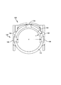
図1−3は、義指100の一実施形態の斜視図、側面図、及び分解図を示す。この実施形態では、義指100は、患者の手に配置された近位端から、患者の手からある距離に位置する遠位端まで延びる4つの主要な相互接続される構成要素を含み得る。これらの構成要素は、近位リング102、遠位リング104、結合先端部106、及びH形ロッカー108を含む。近位リング102及び遠位リング104の各々は、それぞれの本体112、113を有し得る。この実施形態では、本体112、113は、患者の/ユーザの残りの指に固定するように構成された円形又はリング形状を形成し得る。より具体的には、近位リング102の本体112は、ユーザの残りの指の基節骨の周囲にぴったりフィットして固定するように構成され得る。同様に、遠位リング104の本体113は、ユーザの残りの指の中節骨の周囲にぴったりとフィットして固定するように構成され得る。
FIG. 1-3 shows a perspective view, a side view, and an exploded view of one embodiment of the
一連のヒンジは、上述の4つの主要な構成要素を回転接続部によって固定するのに用いられ得る。一実施形態では、これらの回転接続部は、特に、図4−5に詳述された一対の軸線毎に配置されてもよい。より具体的には、図4は、義指100をy軸に対して二等分する中心線Cを示し、図5は、z軸に対して第1のヒンジ接続部110及び第2のヒンジ接続部114(以下に詳述する)と交差する中心線Mを示す。
A series of hinges can be used to secure the four main components described above by a rotary connection. In one embodiment, these rotary connections may be arranged in particular for each pair of axes detailed in FIGS. 4-5. More specifically, FIG. 4 shows a center line C bisecting the
図1−2に示される様々な回転接続部に目を向けると、遠位リング104は、第1ヒンジ接続部110を介して結合先端部106と回転可能に結合し得る。第1ヒンジ接続部110は、図4に関して上述した中心線Cに対して対称である一対の平行なピボットヒンジを含み得る。連結部110のピボットヒンジの各々は、遠位リング104と結合先端部106との間に旋回点を提供し得る。
Turning to the various rotational connections shown in FIGS. 1-2, the
近位リング102は、第2のヒンジ接続部114を介して遠位リング104と回転可能に結合し得る。また、第2ヒンジ連結部114は、義指100の各々の側に位置する中心線Cに対して対称な一対の平行ピボットヒンジを含み得るものであり、その結果として、近位リング102と遠位リング104との間のピボット点を提供する。図5に関して上述したように、中心線Mは、ヒンジ接続部110及び114と交差し、したがって、第1及び第2のヒンジ接続部110、114の両方は、中心線M上にz軸に対して直接的に配置される。
ロッカー108は、結合先端部106と近位リング102との間に延びる、対向する第1及び第2の端部116、118をそれぞれ有するH形を形成し得る。第1の端部116は、H形の第1の分割突起を形成し、z軸に対して中心線Mの下方に位置する第3のヒンジ接続部120(図1−2)を介して結合先端部106と回転可能に結合し得る。第2の端部118は、H形の第2の分割突起を形成し、z軸に対して中心線Mの上方に位置する第4のヒンジ接続部122(図1−2)を介して近位リング102と回転可能に結合し得る。第3及び第4のヒンジ連結部120、122の両方は、ロッカー108と結合先端部106/近位リング102との間にピボット点を提供する中心線Cに対して対称な一対の平行ピボットヒンジを含み得る。
第1、第2、第3、及び/又は第4ヒンジ接続部110、114、120、122のうちの任意の1つ以上は、動作中に指100の過伸展を防止するためにハードストップを装備し得る。例えば、図7に示すハードストップ127は、第1のヒンジ接続部110の、又は遠位リング104と結合先端部106との間の相対的な過回転を防止し得る。機械的なハードストップは、任意の適切なサイズ、形状、及び/又は構成を有し得る。
Any one or more of the first, second, third, and / or
一緒に作用する近位リング102、遠位リング104、結合先端部106、及びH形ロッカー108は、部材を緊張させて座屈の危険性を低減する遠位リング104に対する引張力に応答して結合先端部が関節運動することを可能にする4節リンクシステムを形成する。したがって、近位リング102及び遠位リング104内に固定された患者の残りの指の自然な動き、又は場合によっては隣接する指の動きは、義指100内の現実的な屈曲動作及び伸長動作を作動させるのに用いられ得る。ユーザは、タイピング、楽器演奏、又は手のかなりの器用さを必要とするその他の活動を含む、通常活動の全範囲を実行し得る。
The
ロッカー108のH形は、ロッカー108と結合先端部106との間の第3のヒンジ接続部120がアセンブリの外側又は遠位リング104及び結合先端部106によって画定される物理的境界の外側で生じることを可能にする。この構成は、比較的長い残りの指又は比較的長い中節骨を有するユーザがアセンブリ内の追加のクリアランス空間を利用することを可能にする。残りの指は、さらに炎症及び/又は過敏症から保護されながら、アセンブリ内で十分フィットし得る。それによれば、ロッカー108は、本明細書ではH形の外形を有するものとして記載されている一方で、ロッカー108は、任意の適切なサイズ、形状、種類、及び/又は構成を取り得ることを理解されたい。
The H-shape of the
図1−5に示す実施形態では、結合先端部106は、先端パッド124を含み得る。先端パッド124は、本物の指の手触りを再現する柔らかな手触りのシリコン又は他の材料から形成され得る。これは、把持を補助し、より柔らかいタッチを提供する。一実施形態では、タッチスクリーン機構(図示省略)は、身体の自然電流に反応する容量性タッチスクリーンを操作するための義指を使用することを可能にするために設けられ得る。タッチスクリーン機構は、ユーザが義指の先端を介して自分の身体へ電流を向かわせることを可能にする。
In the embodiment shown in FIGS. 1-5,
また、結合先端部106の一実施形態は、細かい物体の操作を支援するだけでなく、引掻き機能及び剥離機能を提供し、天然の刃が付いた爪を再現する爪126を含み得る。
Also, one embodiment of the
実施形態の義指100は、カスタム設計され、様々な残りの指の長さ(例えば、様々な喪失量の指)を含む様々な異なるユーザ条件に適合するように個別にフィットされる。これに関して、各指100は、特定の患者又はユーザに合うようにカスタマイズされて、元の切断されていない指の長さを一致させることを含む、ユーザの解剖学的関節の関節運動との機械的適合性だけでなく、カスタム機能性の両方を提供し得る。設計上の考慮事項は、指の喪失量、置き換えられる関節の数、及び個々のエンドユーザーに固有のその他の特性を含む。H形ロッカー108は、患者の残りの指の上及びその周囲にフルカバーの「ケージ」を設けるように設計され、それによって、義指装置100内の残りの指を妨げることなく、残りの指を炎症及び/又は過敏症から保護している。H形ロッカー108が装備されている場合、残りの指の長さが近位指節間(「PIP」)関節を十分に越えて延びていても、ユーザは指100内で任意の長さの義指を固定し得る。ユーザが完全に形成されているものの機能していない指を有する場合には、義指100が指の代用品ではなく接合ブレースとして機能するように、結合先端部106は除去されてもよい。
The
より良好な審美性をさらに提供するために、実施形態の指100は、ユーザの肌の色調/色に合った膜及び/又は着色料で被膜されてもよい。付加的な製造プロセス(すなわち、3D印刷)は、各患者の義指100を最適化するために、義指設計の複雑さをカスタマイズするこの能力を促進する。
To further provide better aesthetics, the
実施形態の義指100は、人間の皮膚に対して非刺激性であり、ユーザが快適且つ確実に人工装具を操作することを可能にする任意の適切な構造材料で形成され得る。例示的な材料は、チタン、ステンレス鋼、アルミニウム、シリコン、炭素繊維、ナイロン、プラスチック/ポリマー、木材、ゴム、金、銀、タングステン、フレックスケーブル、ネオプレン、又は任意の他の適切な材料を含む。一実施形態では、義指100の構成要素は、デュラフォーム(登録商標)EXのポリマー材料から3D印刷される。
The
生体適合性材料を使用することで、様々な実施形態の指100は、ユーザの指に外科的に埋め込まれ得る整形外科インプラントとして適用され得る。このオプションは、治療したり修復したりする能力を欠く、指の骨をつぶした損傷を有するユーザに適用され得る。これらの状況では、移植可能な実施形態の義指100は、切断の必要なしにユーザの元の骨に取って代わることができる。
By using a biocompatible material, the
使用するためには、ユーザは、単に近位リング102及び遠位リング104を自分の残りの指にスライドさせて、必要に応じてシムを用いてさらに調整し得る。図6は、近位リング102の本体112が半円形のシム128を装備されている義指100の背面図を示しており、これは、身体112のサイジングが指の可能な膨張、体重増加/損失、又は残りの指のサイズにおける他の製造後の変化を考慮することを可能にするために用いられ得る。さらに詳細には、フィットキット(図示省略)は、各義指100に設けられ、複数のシム128を含み得る。一実施形態では、各シム128は、近位リング102の本体112の内径dに当接するように構成された半円又はU形に近似し、本体112内の対応するシム保持開口132を介して突出するように構成された多数の保持グロメット130を有し得る。各シム128は、異なる厚さtを有することができ、それにより、ユーザにしたがって近位リング102の本体112の内径dをいくつかの増分で本質的に調節することを可能にする。
To use, the user may simply slide the
義指100(調節されたもの又は他のもの)が適所に配置されると、ユーザは、残りの指の自然な動きを利用することができる。義指100の主要な構成要素は、元の指に対してこれまで使用されていたのと同じ認知プロセスを使用して関節運動する。ユーザが複数の指100を身につけた場合、それぞれが個別に操作され得る。
Once the artificial finger 100 (adjusted or otherwise) is in place, the user can take advantage of the natural movement of the remaining fingers. The main components of the
図7は、義指100の一実施形態をユーザの残りの指に設置して調整し、又はフィッティングするための例示的方法150を示すフローチャートを提供する。その方法は、残りの指を近位リング102の本体112に挿入し(152)、残りの指の周囲の本体112の締め付け(154)を評価することから始まる。この評価(154)によって、ユーザ、医療専門家、又は他のアシスタントは、フィットキット又は他の供給源から第1のシム128(156)を選択し得る。次いで、第1のシム128が内径dを規定するように、ユーザは、近位リング102から残りの指(158)を取り外す第1のシム128(160)を本体112の内径dに挿入し得る一方で、保持グロメット130は、シム保持開口部132を介して突出している。第1のシムが設置されると(160)、ユーザは、残りの指を近位リング102に再挿入し(162)、第1のシム128(近位リング102の本体112をすでに規定する)の締め付け(164)を評価し得る。シムされた近位リング102がフィットする場合、方法150は完了し(166)、ユーザは義指100を生体機械的に駆動することを継続し得る。シムされた近位リング102がフィットしない場合、方法150は、進行する前に異なる厚さを有する第2のシムを選択することができるシム(156)を選択する工程に戻し得る。ユーザは、理想的な又は所望のフィットが達成されるまで、様々な厚さの複数のシムを試し得る。もちろん、遠位リング104は、近位リング102及び方法150に関して説明したものと同様の方法で調整され得る。
FIG. 7 provides a flowchart illustrating an
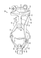
図8−11は、代替の実施形態における義指200の第1の斜視図、平面図、底面図、および第2の斜視図を示す。この実施形態では、義指200は、3つの主に相互に連結された構成要素、すなわち、近位端204及び遠位端206を有するロッカー202、近位連結部208及び遠位連結部210を含む。さらに詳細には、図8−9に示すように、遠位連結部210は、近位連結部208と回転可能に結合し得るもので、次いで、近位連結部208は、ロッカー202の近位端204と結合し得る。ロッカー202の遠位端206は、旋回先端ブレース211と回転可能に結合し得る。旋回先端ブレース211は、図8−9及び図11に示す先端締結ジョイント226を特徴とし、この先端締結ジョイント226は、旋回先端ブレース211に対して受入先端部212が様々な角度で配置されること、及び異なる握力、及び/又は関節運動特性を達成するために義指200の残りの部分に適用されることを可能にする。先端パッド214は、任意の適切な方法で先端212に取り付け得る。
8-11 show a first perspective view, a top view, a bottom view, and a second perspective view of the
2つのケージリングは、ユーザの残りの指を(近位指節間(PIP)関節の近位の1つのリング及びとPIP関節の遠位の別のリングを有する)を保持すると共に、上述された相互連結されたアセンブリを介して残りの指の動きを変える目的のために、連結部に取り付け得る。図6−9に示すように、近位ケージリング216及び遠位ケージリング218は、近位連結部208及び遠位連結部210にそれぞれ取り付け得る。この取り付けは、近位連結部208及び遠位連結部210の各々に位置する汎用リングマウント220によって促進され得る。各汎用リングマウント220は、ケージリング216、218の各々の取り付け突起222を受け入れるように構成されたリングマウント開口224を画定し得る。
Two cage rings hold the user's remaining fingers (with one ring proximal to the proximal interphalangeal (PIP) joint and another ring distal to the PIP joint), as described above. Can be attached to the connection for the purpose of altering the movement of the remaining fingers via the interconnected assembly. As shown in FIGS. 6-9, a
使用中、ユーザ/患者は、義指200の近位及び遠位ケージリング216、218をリングのような自分の残存指の上にスライドさせ得る。各指200は、問題になっている特定のユーザにフィットするようにカスタマイズし得る。ロッカー202、近位及び遠位リンク208、210、及び/又は旋回先端ブレース211は、ユーザの残りの指の長さ又は特定のユーザの他の身体的特徴に適合するようにカスタマイズされてもよく、その結果、義指200がユーザの残りの指に固定されている場合に、残りの指の端部又は先端が受入先端部212の中又はそれに隣接して入れ子にし得る。一実施形態では、受入先端部212は、ユーザの指をさらなる炎症及び/又は過敏症から保護する方法で、残りの指の末端又は先端を受け取るために、湾曲され、又は「カップ状にされ」得る。義指200の構成要素は、関節運動中に本物そっくりに見えるだけでなく、その中に入れ子になった残りの指の末端又は先端を有する受入先端部212は、ロッカー202が関節運動するにつれて本物そっくりな方法で曲がる。
In use, the user / patient may slide the proximal and distal cage rings 216, 218 of the
義指200が各ユーザにカスタムフィットするようにカスタム設計され得る一方で、患者の生理機能に対する製造後の変更が起こり得る。義指200に製造後のカスタマイズ機能を追加するために、近位ケージリング216及び遠位ケージリング218の両方は、取り換え可能であり得るもので、その結果、患者の残りの指に示されたサイジング及び/又は膨張変動に対処するために、それらは様々なサイズのリングと交換され得る。近位及び遠位ケージリング216、218の様々なサイズは、フィットキット(図示省略)内で提供され、ユーザが最も適切なリングサイズをリアルタイムで使用することを可能にし得る。ユーザは、リングマウント開口224及び取り付け突起222を介して、リング216、218をリングマウント220から取り外して、異なるリングをリングマウント220に交換することによって、ケージリングを容易に交換し得る。交換可能リング216、218は、可撓性ポリマー又は人の皮膚に対して非刺激性の他のプラスチックを含む任意の適切な材料で形成され得る。
While the
上述の実施形態における義指100、200は、多くの独自の特徴を示し、様々な医療上の利点を提供する。個人の独自の生理機能とライフスタイルのパターンは、自分の手に期待される機能及び特性に影響する。本明細書に記載の実施形態の義指を使用することで、患者は、仕事中であろうと遊戯中であっても、手の独立制御を取り戻し得る。各装置はカスタム設計され、特定の個人向けに製造され、そして、さらなる微調整及びフィットの調整が製造後のばらつき(例えば、シム又は交換可能なリング)を考慮することを可能にする機能を組み込んで、これらの活動が何を伴うか否かにかかわらず、ユーザの日常活動において生体機械的に駆動され、薄型で、軽量で、高機能的な回復を可能にする方法で、装置をユーザにフィットできるようにする。いくつかの例は、タイピング、ピアノ、又は他の楽器の演奏、及び木工作業などを含む。
The
上述の実施形態の義指は、身体から動力を得られるものであり、それらの連結構成要素は、ユーザが単に自分の残りの指を動かす場合、利用可能又は必要に応じて隣接する指を動かす場合に関節運動する。ユーザ自身の生体力学を駆使して、可能な限り低いプロファイル設計で強度を提供する、シンプルで、洗練され、且つ合理的な設計を可能にすること以外にも、実施形態の義指100、200は、残りの指及び手全体に対する膨張の減少及び循環の増加を含む多くの医学的利益をユーザに提供し、損傷した指及び隣接する指で健全な関節を支持する。
The artificial fingers of the embodiments described above are powered by the body, and their connected components move adjacent fingers as available or as needed, if the user simply moves their remaining fingers If you articulate. In addition to enabling a simple, sophisticated, and rational design that leverages the user's own biomechanics to provide strength with the lowest possible profile design, the
上記の実施形態は、特定の構造、要素、組成、及び方法論的ステップに特有の言語で説明されているが、添付の特許請求の範囲に規定された技術は、記載された特定の構造、要素、組成、及び/又はステップに必ずしも限定されないことを理解されたい。むしろ、特定の態様及びステップは、請求される技術を実施する形態として記載される。本発明の趣旨及び範囲から逸脱することなく技術の多くの実施形態が実施され得るので、本発明は、添付の特許請求の範囲に属する。 Although the above embodiments have been described in language specific to particular structures, elements, compositions, and methodological steps, the techniques defined in the following claims should not be construed as limiting the specific structures, elements or elements described. , Compositions and / or steps. Rather, the specific aspects and steps are described as implementing the claimed technology. Since many embodiments of the technology can be made without departing from the spirit and scope of the invention, the invention resides in the claims hereinafter appended.
Claims (6)
結合先端部と近位リングとの間にそれぞれ第1及び第2ヒンジ接続部を介して回転可能に結合された遠位リングと、
前記結合先端部と前記近位リングとの間にそれぞれ第3及び第4ヒンジ接続部を介して回転可能に結合されたロッカーと、
交換可能な複数のサイジングシムと、備え、
前記第1及び第2のヒンジ接続部は、x軸−z軸面上に形成される中心線を画定し、
前記第3のヒンジ接続部は前記中心線の下方に位置し、
前記第4のヒンジ連結部は、前記中心線の中心線の上方に位置し、その結果、前記近位リングと前記遠位リングとの間の相対回転運動は、前記遠位リングと前記結合先端部との間の相対回転運動を引き起こして、指の自然な閉鎖動作をエミュレートし、
前記ロッカーは、対向する第1及び第2の端部を有するH形を画定し、前記第1の端部は、前記第3のヒンジ接続部に第1の分割突起を形成し、前記第2の端部は、前記第4のヒンジ接続部に第2の分割突起を形成し、
前記サイジングシムの各々は、前記近位及び遠位リングの一方又は両方を規定するように構成されており、
前記近位リング及び前記遠位リングの少なくとも1つは、前記サイジングシムの1つを受け入れ保持するように構成されたシム保持開口を備える、
義指アセンブリ。 A biomechanically driven artificial finger assembly,
A distal ring rotatably coupled between the coupling tip and the proximal ring via first and second hinge connections, respectively;
A rocker rotatably coupled between the coupling tip and the proximal ring via third and fourth hinge connections, respectively;
With multiple interchangeable sizing shims,
The first and second hinge connections define a centerline formed on the x-z plane;
The third hinge connection is located below the center line;
The fourth hinge connection is located above a centerline of the centerline, such that relative rotational movement between the proximal ring and the distal ring causes the distal ring and the coupling tip to move relative to each other. Causing a relative rotational movement between the parts, emulating the natural closing movement of the finger ,
The rocker defines an H-shape having opposing first and second ends, the first end forming a first split protrusion at the third hinge connection, and Forming a second split projection on said fourth hinge connection,
Each of the sizing shims is configured to define one or both of the proximal and distal rings;
At least one of the proximal ring and the distal ring comprises a shim retaining opening configured to receive and retain one of the sizing shims;
Prosthetic finger assembly.
Applications Claiming Priority (5)
| Application Number | Priority Date | Filing Date | Title |
|---|---|---|---|
| US201562111464P | 2015-02-03 | 2015-02-03 | |
| US62/111,464 | 2015-02-03 | ||
| US201562209843P | 2015-08-25 | 2015-08-25 | |
| US62/209,843 | 2015-08-25 | ||
| PCT/US2016/016219 WO2016126736A1 (en) | 2015-02-03 | 2016-02-02 | Bio-mechanical prosthetic finger with h-shaped rocker |
Related Child Applications (1)
| Application Number | Title | Priority Date | Filing Date |
|---|---|---|---|
| JP2019228760A Division JP6826182B2 (en) | 2015-02-03 | 2019-12-19 | Biomechanical prosthesis with H-shaped rocker |
Publications (3)
| Publication Number | Publication Date |
|---|---|
| JP2018503498A JP2018503498A (en) | 2018-02-08 |
| JP2018503498A5 JP2018503498A5 (en) | 2018-09-27 |
| JP6637071B2 true JP6637071B2 (en) | 2020-01-29 |
Family
ID=56564610
Family Applications (4)
| Application Number | Title | Priority Date | Filing Date |
|---|---|---|---|
| JP2017559284A Active JP6637071B2 (en) | 2015-02-03 | 2016-02-02 | Biomechanical artificial finger with H-shaped rocker |
| JP2019228760A Active JP6826182B2 (en) | 2015-02-03 | 2019-12-19 | Biomechanical prosthesis with H-shaped rocker |
| JP2021004073A Active JP7062103B2 (en) | 2015-02-03 | 2021-01-14 | Finger prosthesis |
| JP2022068566A Pending JP2022087353A (en) | 2015-02-03 | 2022-04-19 | Prosthetic finger apparatus |
Family Applications After (3)
| Application Number | Title | Priority Date | Filing Date |
|---|---|---|---|
| JP2019228760A Active JP6826182B2 (en) | 2015-02-03 | 2019-12-19 | Biomechanical prosthesis with H-shaped rocker |
| JP2021004073A Active JP7062103B2 (en) | 2015-02-03 | 2021-01-14 | Finger prosthesis |
| JP2022068566A Pending JP2022087353A (en) | 2015-02-03 | 2022-04-19 | Prosthetic finger apparatus |
Country Status (6)
| Country | Link |
|---|---|
| US (4) | US9707102B2 (en) |
| EP (2) | EP3244840B1 (en) |
| JP (4) | JP6637071B2 (en) |
| AU (3) | AU2016215443B2 (en) |
| CA (2) | CA3158806A1 (en) |
| WO (1) | WO2016126736A1 (en) |
Families Citing this family (11)
| Publication number | Priority date | Publication date | Assignee | Title |
|---|---|---|---|---|
| AU2016215443B2 (en) | 2015-02-03 | 2020-06-18 | RCM Enterprise, LLC | Bio-mechanical prosthetic finger with H-shaped rocker |
| WO2016126739A1 (en) | 2015-02-03 | 2016-08-11 | RCM Enterprise, LLC | Biomechanical finger brace assembly |
| WO2016126732A1 (en) * | 2015-02-03 | 2016-08-11 | RCM Enterprise, LLC | Bio-mechanical prosthetic finger with y-shaped rocker |
| WO2016187133A1 (en) | 2015-05-15 | 2016-11-24 | RCM Enterprise, LLC | Bidirectional biomechanical prosthetic full finger configured for abduction and adduction with mcp pivot and multiple-finger ring |
| JP6720294B2 (en) | 2015-05-15 | 2020-07-08 | アールシーエム エンタープライズ, エルエルシーRcm Enterprise, Llc | Biomechanical bidirectional full prosthesis configured for abduction and adduction with MCP pivot |
| US10235129B1 (en) | 2015-06-29 | 2019-03-19 | Amazon Technologies, Inc. | Joining users to communications via voice commands |
| WO2020106728A1 (en) | 2018-11-19 | 2020-05-28 | The Regents Of The University Of Colorado, A Body Corporate | Prosthetic partial fingers |
| US10744006B2 (en) * | 2019-01-15 | 2020-08-18 | Sai Vipparla | Pet prosthetic |
| EP4102688A4 (en) * | 2020-03-19 | 2024-02-28 | Meidensha Electric Mfg Co Ltd | Electric machine and motor |
| CN112690940B (en) * | 2020-12-23 | 2022-10-11 | 黑龙江中医药大学 | Appliance for preventing and delaying finger joint distortion |
| KR102626907B1 (en) * | 2021-12-15 | 2024-01-17 | 한남대학교 산학협력단 | The functional finger prosthetic |
Family Cites Families (58)
| Publication number | Priority date | Publication date | Assignee | Title |
|---|---|---|---|---|
| US319776A (en) | 1885-06-09 | Tebeitoby | ||
| US984179A (en) | 1910-09-26 | 1911-02-14 | Leonard Aydt | Artificial hand. |
| GB108872A (en) | 1916-11-20 | 1917-08-30 | Enos Robinson | Improvements in or relating to Artificial Hands. |
| GB110333A (en) | 1917-07-24 | 1917-10-18 | Heinrich Troendle | Improved Padding for Artificial Hands. |
| US2598593A (en) * | 1948-09-30 | 1952-05-27 | Ibm | Polycentric articulated finger for artificial hands |
| US2706296A (en) | 1953-05-26 | 1955-04-19 | Maurice J Fletcher | Prosthetic appliance |
| US2867819A (en) | 1954-05-07 | 1959-01-13 | Lloyd E George | Artificial fingers |
| US2876819A (en) | 1955-08-11 | 1959-03-10 | Aristocrat Leather Products In | Combination billfold and purse |
| US3483718A (en) * | 1968-07-30 | 1969-12-16 | Albert C Lodrini | Device for narrowing the diameter of a finger ring |
| US3707963A (en) | 1970-01-21 | 1973-01-02 | M Keropian | Articulated hand brace |
| US4258441A (en) | 1979-08-20 | 1981-03-31 | Hand Rehabilitation Foundation | Dual operated lateral thumb hand prosthesis |
| US4813406A (en) | 1984-05-21 | 1989-03-21 | Ims Limited | Orthopedic splint arrangement |
| US5062855A (en) | 1987-09-28 | 1991-11-05 | Rincoe Richard G | Artifical limb with movement controlled by reversing electromagnet polarity |
| US4986280A (en) * | 1988-07-20 | 1991-01-22 | Arthur D. Little, Inc. | Hand position/measurement control system |
| US4997433A (en) | 1990-01-16 | 1991-03-05 | Marlowe Goble E | Endosteal fixation stud and system |
| IT1264718B1 (it) * | 1993-10-08 | 1996-10-04 | Scuola Superiore Di Studi Universitari E Di Perfezionamento Sant Anna | Dispositivo atto a fornire una retroazione di forza ad un'unita' fisiologica, da utilizzarsi in particolare come interfaccia avanzata |
| US5516249A (en) * | 1994-05-10 | 1996-05-14 | Technical Research Associates, Inc. | Exoskeleton with kinesthetic feedback and robotic control |
| US5718925A (en) | 1995-11-15 | 1998-02-17 | Ossur Hf. | Apparatus for making a prosthesis socket |
| US5848983A (en) | 1995-12-13 | 1998-12-15 | Smith & Nephew, Inc. | Joint flexion and extension and extension splints |
| US5941914A (en) | 1997-10-22 | 1999-08-24 | Sarcos L.C. | Articulated, stacked-plate artificial body part |
| JP3914155B2 (en) | 2000-12-06 | 2007-05-16 | 本田技研工業株式会社 | Multi-finger hand device |
| JP2002345861A (en) | 2001-05-29 | 2002-12-03 | Harada Denshi Kogyo Kk | Finger motion auxiliary device |
| US6481114B1 (en) * | 2001-07-30 | 2002-11-19 | Nazaret Kalajian | Finger ring shim and sizing tool |
| US6908489B2 (en) * | 2003-08-21 | 2005-06-21 | Daniel Dean Didrick | Articulated artificial finger assembly |
| US7592768B2 (en) | 2004-11-17 | 2009-09-22 | Thk Co., Ltd. | Robot joint structure and robot finger |
| US20060212129A1 (en) | 2005-03-16 | 2006-09-21 | Lake Joseph C | Partial hand prosthesis |
| US7361197B2 (en) | 2005-04-01 | 2008-04-22 | Rex Clayton Winfrey | Prosthetic hand having a conformal, compliant grip and opposable, functional thumb |
| DE102005061313A1 (en) | 2005-12-20 | 2007-08-16 | Otto Bock Healthcare Ip Gmbh & Co. Kg | hand prosthesis |
| GB0700975D0 (en) | 2007-01-18 | 2007-02-28 | Ucl Biomedica Plc | Tendon-Integrated prosthesis |
| DE102007005858A1 (en) | 2007-02-01 | 2008-08-14 | Otto Bock Healthcare Products Gmbh | prosthetic finger |
| US20100042229A1 (en) * | 2008-07-03 | 2010-02-18 | Hawk Douglas C | Activity specific finger prosthesis |
| DE102008056520B4 (en) * | 2008-11-08 | 2017-10-19 | Stefan Schulz | finger member |
| JP5516570B2 (en) * | 2009-02-19 | 2014-06-11 | 国立大学法人三重大学 | Wearable motion support device |
| US8262599B2 (en) | 2009-04-09 | 2012-09-11 | Iq Medical Devices, Llc | Splint composition and method for using same |
| DE102009037898B4 (en) * | 2009-08-19 | 2011-09-15 | Otto Bock Healthcare Products Gmbh | gripper |
| WO2011081851A2 (en) | 2009-12-14 | 2011-07-07 | Kinea Design, LLC | One motor finger mechanism |
| EP2536365A2 (en) | 2010-02-19 | 2012-12-26 | Tensegrity Prosthetics Inc. | Joints for prosthetic, orthotic and/or robotic devices |
| US20140078118A1 (en) * | 2010-05-19 | 2014-03-20 | Stephen M. Robb | Hygienic finger protector |
| US8337568B2 (en) | 2010-07-14 | 2012-12-25 | Charles Colin Macduff | Mechanical prosthetic finger device |
| GB2488365A (en) | 2011-02-26 | 2012-08-29 | Ross Michael Neilson | Artificial digit with squeezable sack operation |
| WO2012175038A1 (en) * | 2011-06-22 | 2012-12-27 | The Chinese University Of Hong Kong | Finger prosthesis |
| US8844080B2 (en) * | 2011-11-10 | 2014-09-30 | Ct Usa Llc | Thumb-mountable protective utensil system and kit |
| GB201200167D0 (en) * | 2012-01-05 | 2012-02-15 | Rsl Steeper Group Ltd | An artificial hand component |
| JP5406389B2 (en) | 2012-03-01 | 2014-02-05 | 株式会社フジクラ | Component built-in substrate and manufacturing method thereof |
| US20130268094A1 (en) | 2012-04-10 | 2013-10-10 | Ford Global Technologies, Llc | Add-on capacitive touchscreen aid |
| US8891520B2 (en) | 2012-06-28 | 2014-11-18 | Alcatel Lucent | Scaling redundancy elimination middleboxes |
| ITPI20120094A1 (en) * | 2012-08-28 | 2014-03-01 | Scuola Superiore S Anna | EXOSCHELETRIC WEARABLE DEVICE FOR HAND REHABILITATION |
| US9913737B2 (en) * | 2013-03-13 | 2018-03-13 | Mark Hunter | Mechanical finger |
| US9370430B2 (en) * | 2013-03-29 | 2016-06-21 | RCM Enterprise, LLC | Bio-mechanical prosthetic full finger |
| EP3007609A4 (en) | 2013-06-14 | 2017-06-07 | Osiris Biomed 3D, Llc | Co-located scanning, printing and/or machining devices for medical constructs |
| JP6246379B2 (en) | 2014-09-03 | 2017-12-13 | 三菱電機株式会社 | Image processing apparatus, image processing method, image reading apparatus, and program |
| WO2016126739A1 (en) * | 2015-02-03 | 2016-08-11 | RCM Enterprise, LLC | Biomechanical finger brace assembly |
| AU2016215443B2 (en) | 2015-02-03 | 2020-06-18 | RCM Enterprise, LLC | Bio-mechanical prosthetic finger with H-shaped rocker |
| WO2016126732A1 (en) | 2015-02-03 | 2016-08-11 | RCM Enterprise, LLC | Bio-mechanical prosthetic finger with y-shaped rocker |
| WO2016187133A1 (en) | 2015-05-15 | 2016-11-24 | RCM Enterprise, LLC | Bidirectional biomechanical prosthetic full finger configured for abduction and adduction with mcp pivot and multiple-finger ring |
| JP6720294B2 (en) | 2015-05-15 | 2020-07-08 | アールシーエム エンタープライズ, エルエルシーRcm Enterprise, Llc | Biomechanical bidirectional full prosthesis configured for abduction and adduction with MCP pivot |
| CA2995841C (en) | 2015-08-25 | 2023-09-26 | RCM Enterprise, LLC | Bio-mechanical prosthetic thumb |
| CN110651726A (en) | 2018-06-29 | 2020-01-07 | 尤妮佳股份有限公司 | Absorbent article for animals |
-
2016
- 2016-02-02 AU AU2016215443A patent/AU2016215443B2/en active Active
- 2016-02-02 WO PCT/US2016/016219 patent/WO2016126736A1/en active Application Filing
- 2016-02-02 CA CA3158806A patent/CA3158806A1/en active Pending
- 2016-02-02 JP JP2017559284A patent/JP6637071B2/en active Active
- 2016-02-02 EP EP16747133.3A patent/EP3244840B1/en active Active
- 2016-02-02 CA CA2975446A patent/CA2975446C/en active Active
- 2016-02-02 US US15/013,891 patent/US9707102B2/en active Active
- 2016-02-02 EP EP19198445.9A patent/EP3735942A3/en active Pending
-
2017
- 2017-05-09 US US15/590,684 patent/US9999521B2/en active Active
-
2018
- 2018-05-22 US US15/986,411 patent/US10537448B2/en active Active
-
2019
- 2019-09-13 US US16/570,124 patent/US10806600B2/en active Active
- 2019-12-19 JP JP2019228760A patent/JP6826182B2/en active Active
-
2020
- 2020-09-18 AU AU2020233765A patent/AU2020233765A1/en not_active Abandoned
-
2021
- 2021-01-14 JP JP2021004073A patent/JP7062103B2/en active Active
-
2022
- 2022-04-19 JP JP2022068566A patent/JP2022087353A/en active Pending
- 2022-05-18 AU AU2022203335A patent/AU2022203335B2/en active Active
Also Published As
| Publication number | Publication date |
|---|---|
| JP2018503498A (en) | 2018-02-08 |
| EP3244840A1 (en) | 2017-11-22 |
| US20200000610A1 (en) | 2020-01-02 |
| EP3735942A2 (en) | 2020-11-11 |
| AU2020233765A1 (en) | 2020-10-15 |
| WO2016126736A1 (en) | 2016-08-11 |
| CA3158806A1 (en) | 2016-08-11 |
| US20170020690A1 (en) | 2017-01-26 |
| JP6826182B2 (en) | 2021-02-03 |
| JP2020049262A (en) | 2020-04-02 |
| JP2021053514A (en) | 2021-04-08 |
| AU2022203335A1 (en) | 2022-06-09 |
| CA2975446A1 (en) | 2016-08-11 |
| AU2016215443B2 (en) | 2020-06-18 |
| JP7062103B2 (en) | 2022-05-02 |
| AU2022203335B2 (en) | 2023-11-30 |
| US10537448B2 (en) | 2020-01-21 |
| US10806600B2 (en) | 2020-10-20 |
| CA2975446C (en) | 2023-03-07 |
| US9999521B2 (en) | 2018-06-19 |
| EP3244840B1 (en) | 2019-12-11 |
| US20170239068A1 (en) | 2017-08-24 |
| AU2016215443A1 (en) | 2017-08-17 |
| EP3244840A4 (en) | 2018-12-05 |
| US20180280160A1 (en) | 2018-10-04 |
| JP2022087353A (en) | 2022-06-09 |
| EP3735942A3 (en) | 2021-01-27 |
| US9707102B2 (en) | 2017-07-18 |
Similar Documents
| Publication | Publication Date | Title |
|---|---|---|
| JP6637071B2 (en) | Biomechanical artificial finger with H-shaped rocker | |
| US11596529B2 (en) | Biomechanical finger brace assembly | |
| JP7230122B2 (en) | biomechanical prosthetic thumb | |
| US11173052B2 (en) | Bio-mechanical prosthetic finger with y-shaped rocker |
Legal Events
| Date | Code | Title | Description |
|---|---|---|---|
| A521 | Request for written amendment filed |
Free format text: JAPANESE INTERMEDIATE CODE: A523 Effective date: 20180814 |
|
| A621 | Written request for application examination |
Free format text: JAPANESE INTERMEDIATE CODE: A621 Effective date: 20180814 |
|
| A977 | Report on retrieval |
Free format text: JAPANESE INTERMEDIATE CODE: A971007 Effective date: 20190607 |
|
| A131 | Notification of reasons for refusal |
Free format text: JAPANESE INTERMEDIATE CODE: A131 Effective date: 20190625 |
|
| A521 | Request for written amendment filed |
Free format text: JAPANESE INTERMEDIATE CODE: A523 Effective date: 20190924 |
|
| TRDD | Decision of grant or rejection written | ||
| A01 | Written decision to grant a patent or to grant a registration (utility model) |
Free format text: JAPANESE INTERMEDIATE CODE: A01 Effective date: 20191203 |
|
| A61 | First payment of annual fees (during grant procedure) |
Free format text: JAPANESE INTERMEDIATE CODE: A61 Effective date: 20191219 |
|
| R150 | Certificate of patent or registration of utility model |
Ref document number: 6637071 Country of ref document: JP Free format text: JAPANESE INTERMEDIATE CODE: R150 |
|
| R250 | Receipt of annual fees |
Free format text: JAPANESE INTERMEDIATE CODE: R250 |
|
| R250 | Receipt of annual fees |
Free format text: JAPANESE INTERMEDIATE CODE: R250 |