EP3735931B1 - Handgriff mit doppelfunktion - Google Patents
Handgriff mit doppelfunktion Download PDFInfo
- Publication number
- EP3735931B1 EP3735931B1 EP18898184.9A EP18898184A EP3735931B1 EP 3735931 B1 EP3735931 B1 EP 3735931B1 EP 18898184 A EP18898184 A EP 18898184A EP 3735931 B1 EP3735931 B1 EP 3735931B1
- Authority
- EP
- European Patent Office
- Prior art keywords
- handle
- dual
- protrusions
- purpose handle
- handle according
- Prior art date
- Legal status (The legal status is an assumption and is not a legal conclusion. Google has not performed a legal analysis and makes no representation as to the accuracy of the status listed.)
- Active
Links
- 229920001971 elastomer Polymers 0.000 claims description 5
- 239000000806 elastomer Substances 0.000 claims description 5
- 230000007704 transition Effects 0.000 claims description 5
- 230000000399 orthopedic effect Effects 0.000 claims description 2
- 230000006872 improvement Effects 0.000 description 10
- 238000010586 diagram Methods 0.000 description 6
- 238000003780 insertion Methods 0.000 description 6
- 230000037431 insertion Effects 0.000 description 6
- 238000000034 method Methods 0.000 description 4
- 230000008569 process Effects 0.000 description 4
- 229910000831 Steel Inorganic materials 0.000 description 2
- 230000000694 effects Effects 0.000 description 2
- 238000004519 manufacturing process Methods 0.000 description 2
- 238000002324 minimally invasive surgery Methods 0.000 description 2
- 239000010959 steel Substances 0.000 description 2
- 238000007373 indentation Methods 0.000 description 1
- 238000009434 installation Methods 0.000 description 1
- 230000007246 mechanism Effects 0.000 description 1
Images


Classifications
-
- A—HUMAN NECESSITIES
- A61—MEDICAL OR VETERINARY SCIENCE; HYGIENE
- A61B—DIAGNOSIS; SURGERY; IDENTIFICATION
- A61B50/00—Containers, covers, furniture or holders specially adapted for surgical or diagnostic appliances or instruments, e.g. sterile covers
- A61B50/20—Holders specially adapted for surgical or diagnostic appliances or instruments
-
- B—PERFORMING OPERATIONS; TRANSPORTING
- B25—HAND TOOLS; PORTABLE POWER-DRIVEN TOOLS; MANIPULATORS
- B25B—TOOLS OR BENCH DEVICES NOT OTHERWISE PROVIDED FOR, FOR FASTENING, CONNECTING, DISENGAGING OR HOLDING
- B25B15/00—Screwdrivers
- B25B15/02—Screwdrivers operated by rotating the handle
-
- A—HUMAN NECESSITIES
- A61—MEDICAL OR VETERINARY SCIENCE; HYGIENE
- A61B—DIAGNOSIS; SURGERY; IDENTIFICATION
- A61B17/00—Surgical instruments, devices or methods, e.g. tourniquets
- A61B17/00234—Surgical instruments, devices or methods, e.g. tourniquets for minimally invasive surgery
-
- A—HUMAN NECESSITIES
- A61—MEDICAL OR VETERINARY SCIENCE; HYGIENE
- A61B—DIAGNOSIS; SURGERY; IDENTIFICATION
- A61B17/00—Surgical instruments, devices or methods, e.g. tourniquets
- A61B17/56—Surgical instruments or methods for treatment of bones or joints; Devices specially adapted therefor
- A61B17/58—Surgical instruments or methods for treatment of bones or joints; Devices specially adapted therefor for osteosynthesis, e.g. bone plates, screws, setting implements or the like
- A61B17/88—Osteosynthesis instruments; Methods or means for implanting or extracting internal or external fixation devices
- A61B17/8875—Screwdrivers, spanners or wrenches
-
- B—PERFORMING OPERATIONS; TRANSPORTING
- B25—HAND TOOLS; PORTABLE POWER-DRIVEN TOOLS; MANIPULATORS
- B25B—TOOLS OR BENCH DEVICES NOT OTHERWISE PROVIDED FOR, FOR FASTENING, CONNECTING, DISENGAGING OR HOLDING
- B25B23/00—Details of, or accessories for, spanners, wrenches, screwdrivers
- B25B23/0007—Connections or joints between tool parts
- B25B23/0042—Connection means between screwdriver handle and screwdriver shaft
-
- B—PERFORMING OPERATIONS; TRANSPORTING
- B25—HAND TOOLS; PORTABLE POWER-DRIVEN TOOLS; MANIPULATORS
- B25B—TOOLS OR BENCH DEVICES NOT OTHERWISE PROVIDED FOR, FOR FASTENING, CONNECTING, DISENGAGING OR HOLDING
- B25B23/00—Details of, or accessories for, spanners, wrenches, screwdrivers
- B25B23/16—Handles
-
- B—PERFORMING OPERATIONS; TRANSPORTING
- B25—HAND TOOLS; PORTABLE POWER-DRIVEN TOOLS; MANIPULATORS
- B25G—HANDLES FOR HAND IMPLEMENTS
- B25G1/00—Handle constructions
- B25G1/005—Handle constructions for screwdrivers, wrenches or spanners with additional levers, e.g. for increasing torque
-
- B—PERFORMING OPERATIONS; TRANSPORTING
- B25—HAND TOOLS; PORTABLE POWER-DRIVEN TOOLS; MANIPULATORS
- B25G—HANDLES FOR HAND IMPLEMENTS
- B25G1/00—Handle constructions
- B25G1/06—Handle constructions reversible or adjustable for position
-
- B—PERFORMING OPERATIONS; TRANSPORTING
- B25—HAND TOOLS; PORTABLE POWER-DRIVEN TOOLS; MANIPULATORS
- B25G—HANDLES FOR HAND IMPLEMENTS
- B25G3/00—Attaching handles to the implements
- B25G3/02—Socket, tang, or like fixings
- B25G3/06—Socket, tang, or like fixings with multiple socket, e.g. T-socket
-
- B—PERFORMING OPERATIONS; TRANSPORTING
- B25—HAND TOOLS; PORTABLE POWER-DRIVEN TOOLS; MANIPULATORS
- B25G—HANDLES FOR HAND IMPLEMENTS
- B25G3/00—Attaching handles to the implements
- B25G3/02—Socket, tang, or like fixings
- B25G3/12—Locking and securing devices
- B25G3/18—Locking and securing devices comprising catches or pawls
-
- A—HUMAN NECESSITIES
- A61—MEDICAL OR VETERINARY SCIENCE; HYGIENE
- A61B—DIAGNOSIS; SURGERY; IDENTIFICATION
- A61B17/00—Surgical instruments, devices or methods, e.g. tourniquets
- A61B2017/0046—Surgical instruments, devices or methods, e.g. tourniquets with a releasable handle; with handle and operating part separable
- A61B2017/00464—Surgical instruments, devices or methods, e.g. tourniquets with a releasable handle; with handle and operating part separable for use with different instruments
-
- A—HUMAN NECESSITIES
- A61—MEDICAL OR VETERINARY SCIENCE; HYGIENE
- A61B—DIAGNOSIS; SURGERY; IDENTIFICATION
- A61B17/00—Surgical instruments, devices or methods, e.g. tourniquets
- A61B2017/00477—Coupling
-
- A—HUMAN NECESSITIES
- A61—MEDICAL OR VETERINARY SCIENCE; HYGIENE
- A61B—DIAGNOSIS; SURGERY; IDENTIFICATION
- A61B90/00—Instruments, implements or accessories specially adapted for surgery or diagnosis and not covered by any of the groups A61B1/00 - A61B50/00, e.g. for luxation treatment or for protecting wound edges
- A61B90/06—Measuring instruments not otherwise provided for
- A61B2090/064—Measuring instruments not otherwise provided for for measuring force, pressure or mechanical tension
- A61B2090/066—Measuring instruments not otherwise provided for for measuring force, pressure or mechanical tension for measuring torque
-
- B—PERFORMING OPERATIONS; TRANSPORTING
- B25—HAND TOOLS; PORTABLE POWER-DRIVEN TOOLS; MANIPULATORS
- B25B—TOOLS OR BENCH DEVICES NOT OTHERWISE PROVIDED FOR, FOR FASTENING, CONNECTING, DISENGAGING OR HOLDING
- B25B23/00—Details of, or accessories for, spanners, wrenches, screwdrivers
- B25B23/0007—Connections or joints between tool parts
- B25B23/0035—Connection means between socket or screwdriver bit and tool
-
- B—PERFORMING OPERATIONS; TRANSPORTING
- B27—WORKING OR PRESERVING WOOD OR SIMILAR MATERIAL; NAILING OR STAPLING MACHINES IN GENERAL
- B27F—DOVETAILED WORK; TENONS; SLOTTING MACHINES FOR WOOD OR SIMILAR MATERIAL; NAILING OR STAPLING MACHINES
- B27F1/00—Dovetailed work; Tenons; Making tongues or grooves; Groove- and- tongue jointed work; Finger- joints
- B27F1/02—Making tongues or grooves, of indefinite length
Definitions
- the invention relates to the technical field of orthopedic medical devices and tools, in particular to a dual-purpose handle.
- handles used in the clinic are poor in interchangeability and single in functions; in this way, the types of the handles in a single operation are various, and the number is increased; the labor cost and the device acquisition cost are increased greatly, and moreover the acting force applied to the devices by hand are not liable to control; the adjustable range is small, and consequently the risk of damage to skeletons and relevant devices is increased.
- CN 204 160 394 U describes an interchangeable multi-purpose handle comprising a rod part and a handle part, wherein at least one end of the rod part is formed with a wedge-shaped head, the middle section of the rod part is formed with a pair of symmetrical raised ribs, the handle part is axially provided with a channel matching the rod part, and radially provided with a through hole for the rod part to pass through, and at least one end of the handle part is formed with a clamping handle part.
- the interchangeable multi-purpose handle can be used as a driver when the rod part and the handle part are connected in the same straight line.
- the interchangeable multi-purpose handle can be used as a wrench when the rod part and the handle part are connected perpendicular to each other.
- US 2009126538 A1 describes a body having one or more apertures to receive a variety of detachable utility inserts.
- the body being shaped with a spherical ball retainer member and/or a torsion bar for engaging a corresponding spherical indentation and notch formed on the utility insert.
- the body further includes a lever for locking and unlocking the utility insert from the body.
- CN 103 156 673 B describes a rapid connection handle comprising a gripping handle and an insertion sleeve formed in the gripping handle, further comprising a movable sleeve provided in the insertion sleeve and slidably connected to the insertion sleeve, wherein a lateral through hole is formed on a side wall of the movable sleeve, a steel ball is provided in the above-mentioned lateral through hole, and the diameter of the steel ball is greater than the diameter of the lateral through hole.
- An inclined surface is formed on a side wall of the above-mentioned insertion sleeve. The inclined surface faces the bottom of the insertion sleeve and the position thereof corresponds to the position of the lateral through hole.
- the movable sleeve and the insertion sleeve are slidably connected by a spring.
- CN 205 325 538 U describes an open end wrench comprising a handle, a connecting rod and a clamp with different specifications, wherein a mounting hole is provided on the handle, an inner end of the connecting rod is detachably inserted into the mounting hole.
- the mounting hole comprises a first mounting hole and a second mounting hole, wherein the first mounting hole is formed in a side wall of the handle, and the second mounting hole is formed at an end of the handle 12.
- DE 2008 009123 U1 describes a screwdriver handle suitable for fixing a drill attachment, having openings with the diameter of 7 mm at both the front end and the lower side. Depending on the available space a user can decide whether to place the drill attachment at the front end of the handle or at right angles to the handle.
- US 2004/250378 A1 describes a handle for a driving tool, the drive tool having a drive-tool handle.
- the handle has a body which is sized for hand gripping.
- the body has a longitudinal axis and a transverse axis.
- Formed in the body is a longitudinal bore, which has a cross section, extending from a first opening to a second opening in the body.
- a transverse bore extends from an opening in a side wall of the body and intersects the longitudinal bore.
- US 4 787 276 A describes a hand tool for transferring torque having a handle, wherein tool implement blades may be alternately mounted upon the handle in three operative positions.
- a slot defined at one end of the handle allows installation of an implement having a forming head secured thereto such that the implement axis is parallel or lateral to the handle axis.
- US 2016/129569 A1 describes a torque wrench comprising a solenoid driven release mechanism and a transceiver for wirelessly transmitting and receiving parameter set to detect the applied torque and to signal the operator that the torque set point has been reached.
- US 2009/288526 A1 describes a hand tool with warning effect.
- a torque sensor an operation torque detected by the torque sensor is transmitted to the processing unit.
- a processing unit shuts off the warning sound generator and a music player can play music for a user to listen to.
- the processing unit turns on the warning sound generator to emit a warning signal to alert the user.
- DE 2004 014326 U1 discloses an electronic wrench comprising a key body with a handle and at least one driving head, the handle being provided with electronics in a suitable position, the electronics comprising a voltmeter with a distance X from the centre of the driving head, and from which electronics can calculate a torque and display the torque value on a display.
- the invention aims to provide a dual-purpose handle with the simple structure and easy operation, and the requirement of straight connection or T type connection between the dual-purpose handle and functional parts can be met.
- the invention relates to a dual-purpose handle, comprising a body, and mounting holes are arranged in the body, and used to connect the functional parts.
- the mounting holes are arranged in the body axially and radially.
- the mounting holes arranged in the body axially and radially enable the connection between the handle and the functional parts to switch between a straight type and a T type conveniently and efficiently.
- Different connection modes can output different torsional moments under the effect of the same operating force so that the control range is expanded.
- clamping stop devices which are fit with the functional parts are arranged in the mounting holes.
- the clamping stop devices are arranged in the mounting holes. When the functional parts are connected with the handle, the functional parts can be fixed through the clamping stop devices axially, and prevented from being rotated in the body 1 cavity of the handle.
- the clamping stop devices are arranged as protrusions corresponding to grooves of the functional parts.
- the protrusions are elastomers.
- the elastic protrusions arranged on the handle can locate the functional parts automatically.
- the functional parts can be disengaged along the body cavity of the handle conveniently.
- the free ends of the protrusions are in smooth arc transition.
- the smooth arc transition of the free ends of the protrusions enables the protrusions to slide in or out from grooves of the functional parts matched with the protrusions more smoothly.
- the protrusions and the body are arranged integrally and are in seamless connection.
- the handle has the advantages of low manufacturing cost, firm combination, long service life and the like.
- the mounting holes are arranged as through holes.
- the axial hole and the radial hole of the handle are arranged as through holes; in this way, the handle is applicable for guide pins in different sizes to penetrate, and the handle is suitable for minimally invasive surgery; the application range of the handle is further expanded.
- anti-slip grooves or anti-slip protrusions are arranged on the body.
- the anti-slip grooves or the anti-slip protrusions arranged on the body enable operating personnel to hold the handle in the using process more securely, and apply the acting force more conveniently.
- the body is made of ixef 1022 plastic.
- a strain gauge torque sensor is pasted on the surface of the body.
- the strain gauge torque sensor is pasted on the surface of the body, and can be used to measure the torque applied to the functional parts by the operating personnel in real time; in this way, the risk is reduced greatly.
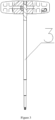
- Figure 1 shows a structure diagram of the dual-purpose handle.
- the body 1 of the dual-purpose handle is made of ixef 1022 plastic.
- the anti-slip grooves or the anti-slip protrusions arranged on the body enable operating personnel to hold the handle in the using process more securely, and apply the acting force more conveniently.
- a radial mounting hole 112 and an axial mounting hole 111 are arranged in the body 1 of the dual-purpose handle radially and axially.
- the mounting holes are arranged as 1/4-inch international common holes so as to expand the application range of the handle as far as possible, and the types and number of the handle are reduced as far as possible.
- the functional parts 3 are connected with the body 1 through the above mounting holes (111 and 112).
- the radial clamping stop device 21 and the axial clamping stop device 22 are arranged on the body 1 of the dual-purpose handle radially and axially.
- the clamping stop devices 21 and 22 are preferably designed as protrusions corresponding to the grooves of the functional parts, and can also be arranged in other forms meeting the clamping stop function.
- the protrusions arranged on the handle are elastomers, and the free ends of the elastomers are in smooth arc transition.
- the elastomers can locate the functional parts automatically; through pulling of the elastic protrusions arranged on the handle, the functional parts 3 can be disengaged along the body 1 cavity of the handle conveniently.
- the smooth arc transition of the free ends of the protrusions enables the protrusions to slide in or out from the grooves of the functional parts matched with the protrusions more smoothly.
- the protrusions and the body can be arranged integrally.
- Figure 2 shows a diagram of a usage mode of the dual-purpose handle in the first embodiment of the invention.
- the functional parts 3 are in straight connection with the body through the axial mounting hole 111 on the body 1;
- Figure 3 shows a diagram of a usage mode of the dual-purpose handle in the second embodiment of the invention.
- the functional parts 3 are in T-type connection with the body through the radial mounting hole 112 on the body 1.
- the arms of the acting forces are different in the above two connection modes are different so that the controllable range of the torque is expanded.
- the straight connection can achieve small torque, while the T type connection is used to achieve large torque; in this way, the operability of the handle in the using process is improved.
- the strain gauge torque sensor is pasted on the surface of the body, and shows data on a display screen in time so as to measure the torque applied to the functional parts by the operating personnel in real time; in this way, the operating process is more accurate and effective, and the risk is reduced greatly.
- the axial hole and the radial hole of the handle are arranged as through holes; in this way, the handle the handle can be suitable for minimally invasive surgery, and is applicable for guide pins to penetrate; the application range of the handle is further expanded.
Landscapes
- Health & Medical Sciences (AREA)
- Engineering & Computer Science (AREA)
- Mechanical Engineering (AREA)
- Surgery (AREA)
- Life Sciences & Earth Sciences (AREA)
- Molecular Biology (AREA)
- Heart & Thoracic Surgery (AREA)
- Medical Informatics (AREA)
- Biomedical Technology (AREA)
- Animal Behavior & Ethology (AREA)
- General Health & Medical Sciences (AREA)
- Public Health (AREA)
- Veterinary Medicine (AREA)
- Nuclear Medicine, Radiotherapy & Molecular Imaging (AREA)
- Orthopedic Medicine & Surgery (AREA)
- Surgical Instruments (AREA)
- Prostheses (AREA)
- Details Of Spanners, Wrenches, And Screw Drivers And Accessories (AREA)
Claims (8)
- Doppelzweckiger Griff für die orthopädische Chirurgie, umfassend einen Körper (1);wobei am Körper (1) Befestigungslöcher (11) zur Herstellung von Verbindungen mit Funktionsteilen vorgesehen sind,wobei sowohl in axialer als auch in radialer Richtung des Körpers (1) Befestigungslöcher (11) angeordnet sind,dadurch gekennzeichnet, dassein Dehnungsmessstreifen-Drehmomentsensor an der Oberfläche des Körpers (1) geklebt ist, um Daten sofort an einen Bildschirm zu senden, so dass vom Bediener auf die Funktionsteile ausgeübte Drehmoment in Echtzeit überwacht wird.
- Doppelzweckiger Griff nach Anspruch 1, dadurch gekennzeichnet, dass in die Befestigungslöcher (11) eine Verriegelungsvorrichtung versehen sind, die an die Funktionsteile angepasst ist.
- Doppelzweckiger Griff nach Anspruch 2, dadurch gekennzeichnet, dass die Verriegelungsvorrichtung als ein der Nut des Funktionsteils (3) entsprechender Vorsprung ausgebildet ist.
- Doppelzweckiger Griff nach Anspruch 3, dadurch gekennzeichnet, dass der Vorsprung ein Elastomer ist.
- Doppelzweckiger Griff nach Anspruch 4, dadurch gekennzeichnet, dass das freie Ende des Vorsprungs einen glatten Bogenübergang bildet.
- Doppelzweckiger Griff nach Anspruch 5, dadurch gekennzeichnet, dass der Vorsprung und der Körper (1) einstückig geformt und nahtlos verbunden sind.
- Doppelzweckiger Griff nach Anspruch 1, dadurch gekennzeichnet, dass die Befestigungslöcher als Durchgangslöcher ausgebildet sind.
- Doppelzweckiger Griff nach Anspruch 1, dadurch gekennzeichnet, dass an dem Körper (1) eine Anti-Rutsch-Rille oder ein Anti-Rutsch-Vorsprung vorgesehen ist.
Applications Claiming Priority (2)
| Application Number | Priority Date | Filing Date | Title |
|---|---|---|---|
| CN201810013119.0A CN108210081A (zh) | 2018-01-05 | 2018-01-05 | 一种双用手柄 |
| PCT/CN2018/100316 WO2019134366A1 (zh) | 2018-01-05 | 2018-08-14 | 一种双用手柄 |
Publications (3)
| Publication Number | Publication Date |
|---|---|
| EP3735931A1 EP3735931A1 (de) | 2020-11-11 |
| EP3735931A4 EP3735931A4 (de) | 2021-10-06 |
| EP3735931B1 true EP3735931B1 (de) | 2024-01-10 |
Family
ID=62643301
Family Applications (1)
| Application Number | Title | Priority Date | Filing Date |
|---|---|---|---|
| EP18898184.9A Active EP3735931B1 (de) | 2018-01-05 | 2018-08-14 | Handgriff mit doppelfunktion |
Country Status (4)
| Country | Link |
|---|---|
| US (1) | US11517386B2 (de) |
| EP (1) | EP3735931B1 (de) |
| CN (1) | CN108210081A (de) |
| WO (1) | WO2019134366A1 (de) |
Families Citing this family (3)
| Publication number | Priority date | Publication date | Assignee | Title |
|---|---|---|---|---|
| CN108210081A (zh) * | 2018-01-05 | 2018-06-29 | 中国人民解放军第四军医大学 | 一种双用手柄 |
| CN108938074B (zh) * | 2018-07-11 | 2021-03-02 | 上海锐植医疗器械有限公司 | 一种棘轮手柄 |
| US11440177B2 (en) * | 2020-03-30 | 2022-09-13 | Shukla Medical | Handle assembly for a surgical tool |
Family Cites Families (26)
| Publication number | Priority date | Publication date | Assignee | Title |
|---|---|---|---|---|
| US2950746A (en) * | 1957-08-12 | 1960-08-30 | Gen Metals Corp | Clutched handle for tool shanks |
| US3752202A (en) * | 1972-02-22 | 1973-08-14 | Vaco Products Co | Hand fastener driving tool |
| US4056020A (en) * | 1976-08-24 | 1977-11-01 | Joseph Coviello | Hand-grippable driver-fastener tool |
| US4787276A (en) * | 1987-05-11 | 1988-11-29 | Condon Harry F | Tool handle with interchangeable blades and alternate orientation |
| US4996896A (en) * | 1990-03-09 | 1991-03-05 | Armand Bachand | Dual use screwdriver |
| US5544379A (en) * | 1994-07-19 | 1996-08-13 | Kalloy Industrial Co., Ltd. | Multifunctional quick release for a bicycle |
| US5477758A (en) * | 1994-09-19 | 1995-12-26 | Cunningham; Jerry L. | Automotive flywheel and belt tension tool kit |
| US5743737A (en) * | 1996-02-09 | 1998-04-28 | Kirk G. Hawn | Dental instrument |
| DE29807944U1 (de) * | 1998-05-04 | 1998-10-08 | Gmeilbauer Engelbert | Schraubendrehergriff |
| US6378402B1 (en) * | 2000-02-29 | 2002-04-30 | Black & Decker Inc. | Hand tool |
| US6922870B2 (en) * | 2003-06-11 | 2005-08-02 | William L. Tontz, Sr. | Torque magnifying handle for driving tool |
| DE202004014326U1 (de) * | 2004-09-15 | 2005-01-13 | Hsien, Chih-Ching, Feng Yuan | Elektronischer Schraubenschlüssel |
| US7287450B1 (en) * | 2006-08-02 | 2007-10-30 | Youn Chyuan Liao | Tool device having rotatable driving shank |
| US8087330B2 (en) * | 2006-12-05 | 2012-01-03 | Chih-Ching Hsieh | Hand tool with warning effect |
| US8096213B2 (en) * | 2007-11-16 | 2012-01-17 | Neil Miers | Utility insert tool with spherical retaining ball member and torsion bar for securing detachable utility inserts |
| DE202008009123U1 (de) * | 2008-07-07 | 2008-09-04 | Hans Viering Gmbh & Co. Kg | T-Schraubendrehergriff, geeignet für sechskantige doppelseitige Bitaufsätze, die entweder am vorderen Ende des Handgriffs oder im rechten Winkel zum Griff angesteckt werden |
| US8051748B2 (en) * | 2009-07-21 | 2011-11-08 | Jack Lin | Small but effective toolkit |
| CN102507069A (zh) * | 2011-10-13 | 2012-06-20 | 深圳市特力德精密工具有限公司 | 数显扭矩头及数显扭矩扳手 |
| CN103156673B (zh) * | 2013-03-26 | 2015-07-01 | 江苏荷普医疗器械有限公司 | 一种快接手柄 |
| WO2014201243A2 (en) * | 2013-06-13 | 2014-12-18 | Stanley Black & Decker, Inc. | Wireless tool system |
| CN103817661A (zh) * | 2014-01-07 | 2014-05-28 | 常州奥斯迈医疗器械有限公司 | 快拆式直形快接手柄 |
| CN204160394U (zh) * | 2014-09-10 | 2015-02-18 | 嵊州市丹青工具有限公司 | 一种互换多用手柄 |
| CN205325538U (zh) * | 2016-01-08 | 2016-06-22 | 冯灼星 | 一种新型开口扳手 |
| CN205763720U (zh) * | 2016-05-25 | 2016-12-07 | 北京科技大学 | 一种连铸结晶器电磁搅拌器电磁力矩的测量装置 |
| CN206216564U (zh) * | 2016-12-01 | 2017-06-06 | 缙云县阪喜达包装有限公司 | 一种五金扳手 |
| CN108210081A (zh) * | 2018-01-05 | 2018-06-29 | 中国人民解放军第四军医大学 | 一种双用手柄 |
-
2018
- 2018-01-05 CN CN201810013119.0A patent/CN108210081A/zh active Pending
- 2018-08-14 WO PCT/CN2018/100316 patent/WO2019134366A1/zh unknown
- 2018-08-14 US US16/628,261 patent/US11517386B2/en active Active
- 2018-08-14 EP EP18898184.9A patent/EP3735931B1/de active Active
Also Published As
| Publication number | Publication date |
|---|---|
| US11517386B2 (en) | 2022-12-06 |
| US20200214781A1 (en) | 2020-07-09 |
| EP3735931A4 (de) | 2021-10-06 |
| CN108210081A (zh) | 2018-06-29 |
| EP3735931A1 (de) | 2020-11-11 |
| WO2019134366A1 (zh) | 2019-07-11 |
Similar Documents
| Publication | Publication Date | Title |
|---|---|---|
| EP3735931B1 (de) | Handgriff mit doppelfunktion | |
| EP1878524B1 (de) | Antriebswerkzeuganordung | |
| US6598500B1 (en) | Double-nut tool and method of setting the toe angle of a vehicle wheel | |
| US7913592B2 (en) | Tool holding device | |
| US8220135B2 (en) | Compound tool with screwdriver attachment | |
| US6436103B1 (en) | Drill guide and plate attachment mechanism for orthopedic plating | |
| EP0952901B1 (de) | Werkzeugantriebadapter | |
| US8020876B2 (en) | Tool having clamping chuck | |
| US7044028B1 (en) | Socket wrench apparatus | |
| CN202377572U (zh) | 电动工具及卡盘 | |
| US20060254394A1 (en) | Fastener driver | |
| JP2007501063A5 (de) | ||
| EP3160687B1 (de) | Schraubenzieher | |
| US20060230885A1 (en) | Compound hand tool | |
| US6626071B2 (en) | Multi-functional hand tool assembly with storage handle and multiple tool attachments | |
| EP1078718A2 (de) | Bohr- und Schraub-Werkzeug | |
| US20140196580A1 (en) | Multi-Bit Power Driver | |
| US20240173060A1 (en) | Adapter device for surgical instruments | |
| US4934717A (en) | Quick exchange tool holder device | |
| US7010822B1 (en) | Connecting device for connecting a main tool and an auxiliary tool of a combination tool | |
| US7497647B2 (en) | Device for orienting a work tool at a predetermined attitude relative to a work piece | |
| CN110313971B (zh) | 导引式角度钻 | |
| JP3982599B2 (ja) | ドライバー用ソケット | |
| EP0087972A2 (de) | Zusatzeinrichtung für kraftangetriebenes Werkzeug | |
| CN109199566B (zh) | 椎弓根螺钉上钉器 |
Legal Events
| Date | Code | Title | Description |
|---|---|---|---|
| STAA | Information on the status of an ep patent application or granted ep patent |
Free format text: STATUS: THE INTERNATIONAL PUBLICATION HAS BEEN MADE |
|
| PUAI | Public reference made under article 153(3) epc to a published international application that has entered the european phase |
Free format text: ORIGINAL CODE: 0009012 |
|
| STAA | Information on the status of an ep patent application or granted ep patent |
Free format text: STATUS: REQUEST FOR EXAMINATION WAS MADE |
|
| 17P | Request for examination filed |
Effective date: 20200515 |
|
| AK | Designated contracting states |
Kind code of ref document: A1 Designated state(s): AL AT BE BG CH CY CZ DE DK EE ES FI FR GB GR HR HU IE IS IT LI LT LU LV MC MK MT NL NO PL PT RO RS SE SI SK SM TR |
|
| AX | Request for extension of the european patent |
Extension state: BA ME |
|
| DAV | Request for validation of the european patent (deleted) | ||
| DAX | Request for extension of the european patent (deleted) | ||
| A4 | Supplementary search report drawn up and despatched |
Effective date: 20210903 |
|
| RIC1 | Information provided on ipc code assigned before grant |
Ipc: B25B 23/00 20060101ALI20210830BHEP Ipc: B25G 3/18 20060101ALI20210830BHEP Ipc: B25G 1/06 20060101ALI20210830BHEP Ipc: A61B 17/00 20060101ALI20210830BHEP Ipc: A61B 50/20 20160101AFI20210830BHEP |
|
| GRAP | Despatch of communication of intention to grant a patent |
Free format text: ORIGINAL CODE: EPIDOSNIGR1 |
|
| STAA | Information on the status of an ep patent application or granted ep patent |
Free format text: STATUS: GRANT OF PATENT IS INTENDED |
|
| INTG | Intention to grant announced |
Effective date: 20231011 |
|
| GRAS | Grant fee paid |
Free format text: ORIGINAL CODE: EPIDOSNIGR3 |
|
| P01 | Opt-out of the competence of the unified patent court (upc) registered |
Effective date: 20231101 |
|
| GRAA | (expected) grant |
Free format text: ORIGINAL CODE: 0009210 |
|
| STAA | Information on the status of an ep patent application or granted ep patent |
Free format text: STATUS: THE PATENT HAS BEEN GRANTED |
|
| AK | Designated contracting states |
Kind code of ref document: B1 Designated state(s): AL AT BE BG CH CY CZ DE DK EE ES FI FR GB GR HR HU IE IS IT LI LT LU LV MC MK MT NL NO PL PT RO RS SE SI SK SM TR |
|
| REG | Reference to a national code |
Ref country code: GB Ref legal event code: FG4D |
|
| REG | Reference to a national code |
Ref country code: CH Ref legal event code: EP |
|
| REG | Reference to a national code |
Ref country code: DE Ref legal event code: R096 Ref document number: 602018064118 Country of ref document: DE |
|
| REG | Reference to a national code |
Ref country code: IE Ref legal event code: FG4D |
|
| REG | Reference to a national code |
Ref country code: LT Ref legal event code: MG9D |
|
| REG | Reference to a national code |
Ref country code: NL Ref legal event code: MP Effective date: 20240110 |