EP3734701A1 - Separator und elektrochemische vorrichtung damit - Google Patents
Separator und elektrochemische vorrichtung damit Download PDFInfo
- Publication number
- EP3734701A1 EP3734701A1 EP19862459.5A EP19862459A EP3734701A1 EP 3734701 A1 EP3734701 A1 EP 3734701A1 EP 19862459 A EP19862459 A EP 19862459A EP 3734701 A1 EP3734701 A1 EP 3734701A1
- Authority
- EP
- European Patent Office
- Prior art keywords
- binder polymer
- separator
- electrochemical device
- coating layer
- porous coating
- Prior art date
- Legal status (The legal status is an assumption and is not a legal conclusion. Google has not performed a legal analysis and makes no representation as to the accuracy of the status listed.)
- Pending
Links
Images


Classifications
-
- H—ELECTRICITY
- H01—ELECTRIC ELEMENTS
- H01M—PROCESSES OR MEANS, e.g. BATTERIES, FOR THE DIRECT CONVERSION OF CHEMICAL ENERGY INTO ELECTRICAL ENERGY
- H01M50/00—Constructional details or processes of manufacture of the non-active parts of electrochemical cells other than fuel cells, e.g. hybrid cells
- H01M50/40—Separators; Membranes; Diaphragms; Spacing elements inside cells
- H01M50/409—Separators, membranes or diaphragms characterised by the material
- H01M50/449—Separators, membranes or diaphragms characterised by the material having a layered structure
-
- H—ELECTRICITY
- H01—ELECTRIC ELEMENTS
- H01M—PROCESSES OR MEANS, e.g. BATTERIES, FOR THE DIRECT CONVERSION OF CHEMICAL ENERGY INTO ELECTRICAL ENERGY
- H01M50/00—Constructional details or processes of manufacture of the non-active parts of electrochemical cells other than fuel cells, e.g. hybrid cells
- H01M50/40—Separators; Membranes; Diaphragms; Spacing elements inside cells
- H01M50/46—Separators, membranes or diaphragms characterised by their combination with electrodes
- H01M50/461—Separators, membranes or diaphragms characterised by their combination with electrodes with adhesive layers between electrodes and separators
-
- H—ELECTRICITY
- H01—ELECTRIC ELEMENTS
- H01G—CAPACITORS; CAPACITORS, RECTIFIERS, DETECTORS, SWITCHING DEVICES, LIGHT-SENSITIVE OR TEMPERATURE-SENSITIVE DEVICES OF THE ELECTROLYTIC TYPE
- H01G11/00—Hybrid capacitors, i.e. capacitors having different positive and negative electrodes; Electric double-layer [EDL] capacitors; Processes for the manufacture thereof or of parts thereof
- H01G11/52—Separators
-
- H—ELECTRICITY
- H01—ELECTRIC ELEMENTS
- H01M—PROCESSES OR MEANS, e.g. BATTERIES, FOR THE DIRECT CONVERSION OF CHEMICAL ENERGY INTO ELECTRICAL ENERGY
- H01M10/00—Secondary cells; Manufacture thereof
- H01M10/05—Accumulators with non-aqueous electrolyte
- H01M10/052—Li-accumulators
-
- H—ELECTRICITY
- H01—ELECTRIC ELEMENTS
- H01M—PROCESSES OR MEANS, e.g. BATTERIES, FOR THE DIRECT CONVERSION OF CHEMICAL ENERGY INTO ELECTRICAL ENERGY
- H01M10/00—Secondary cells; Manufacture thereof
- H01M10/05—Accumulators with non-aqueous electrolyte
- H01M10/052—Li-accumulators
- H01M10/0525—Rocking-chair batteries, i.e. batteries with lithium insertion or intercalation in both electrodes; Lithium-ion batteries
-
- H—ELECTRICITY
- H01—ELECTRIC ELEMENTS
- H01M—PROCESSES OR MEANS, e.g. BATTERIES, FOR THE DIRECT CONVERSION OF CHEMICAL ENERGY INTO ELECTRICAL ENERGY
- H01M50/00—Constructional details or processes of manufacture of the non-active parts of electrochemical cells other than fuel cells, e.g. hybrid cells
- H01M50/40—Separators; Membranes; Diaphragms; Spacing elements inside cells
- H01M50/403—Manufacturing processes of separators, membranes or diaphragms
-
- H—ELECTRICITY
- H01—ELECTRIC ELEMENTS
- H01M—PROCESSES OR MEANS, e.g. BATTERIES, FOR THE DIRECT CONVERSION OF CHEMICAL ENERGY INTO ELECTRICAL ENERGY
- H01M50/00—Constructional details or processes of manufacture of the non-active parts of electrochemical cells other than fuel cells, e.g. hybrid cells
- H01M50/40—Separators; Membranes; Diaphragms; Spacing elements inside cells
- H01M50/409—Separators, membranes or diaphragms characterised by the material
- H01M50/411—Organic material
- H01M50/414—Synthetic resins, e.g. thermoplastics or thermosetting resins
- H01M50/42—Acrylic resins
-
- H—ELECTRICITY
- H01—ELECTRIC ELEMENTS
- H01M—PROCESSES OR MEANS, e.g. BATTERIES, FOR THE DIRECT CONVERSION OF CHEMICAL ENERGY INTO ELECTRICAL ENERGY
- H01M50/00—Constructional details or processes of manufacture of the non-active parts of electrochemical cells other than fuel cells, e.g. hybrid cells
- H01M50/40—Separators; Membranes; Diaphragms; Spacing elements inside cells
- H01M50/409—Separators, membranes or diaphragms characterised by the material
- H01M50/411—Organic material
- H01M50/414—Synthetic resins, e.g. thermoplastics or thermosetting resins
- H01M50/426—Fluorocarbon polymers
-
- H—ELECTRICITY
- H01—ELECTRIC ELEMENTS
- H01M—PROCESSES OR MEANS, e.g. BATTERIES, FOR THE DIRECT CONVERSION OF CHEMICAL ENERGY INTO ELECTRICAL ENERGY
- H01M50/00—Constructional details or processes of manufacture of the non-active parts of electrochemical cells other than fuel cells, e.g. hybrid cells
- H01M50/40—Separators; Membranes; Diaphragms; Spacing elements inside cells
- H01M50/409—Separators, membranes or diaphragms characterised by the material
- H01M50/431—Inorganic material
-
- H—ELECTRICITY
- H01—ELECTRIC ELEMENTS
- H01M—PROCESSES OR MEANS, e.g. BATTERIES, FOR THE DIRECT CONVERSION OF CHEMICAL ENERGY INTO ELECTRICAL ENERGY
- H01M50/00—Constructional details or processes of manufacture of the non-active parts of electrochemical cells other than fuel cells, e.g. hybrid cells
- H01M50/40—Separators; Membranes; Diaphragms; Spacing elements inside cells
- H01M50/409—Separators, membranes or diaphragms characterised by the material
- H01M50/443—Particulate material
-
- H—ELECTRICITY
- H01—ELECTRIC ELEMENTS
- H01M—PROCESSES OR MEANS, e.g. BATTERIES, FOR THE DIRECT CONVERSION OF CHEMICAL ENERGY INTO ELECTRICAL ENERGY
- H01M50/00—Constructional details or processes of manufacture of the non-active parts of electrochemical cells other than fuel cells, e.g. hybrid cells
- H01M50/40—Separators; Membranes; Diaphragms; Spacing elements inside cells
- H01M50/409—Separators, membranes or diaphragms characterised by the material
- H01M50/446—Composite material consisting of a mixture of organic and inorganic materials
-
- H—ELECTRICITY
- H01—ELECTRIC ELEMENTS
- H01M—PROCESSES OR MEANS, e.g. BATTERIES, FOR THE DIRECT CONVERSION OF CHEMICAL ENERGY INTO ELECTRICAL ENERGY
- H01M50/00—Constructional details or processes of manufacture of the non-active parts of electrochemical cells other than fuel cells, e.g. hybrid cells
- H01M50/40—Separators; Membranes; Diaphragms; Spacing elements inside cells
- H01M50/409—Separators, membranes or diaphragms characterised by the material
- H01M50/449—Separators, membranes or diaphragms characterised by the material having a layered structure
- H01M50/451—Separators, membranes or diaphragms characterised by the material having a layered structure comprising layers of only organic material and layers containing inorganic material
-
- H—ELECTRICITY
- H01—ELECTRIC ELEMENTS
- H01M—PROCESSES OR MEANS, e.g. BATTERIES, FOR THE DIRECT CONVERSION OF CHEMICAL ENERGY INTO ELECTRICAL ENERGY
- H01M50/00—Constructional details or processes of manufacture of the non-active parts of electrochemical cells other than fuel cells, e.g. hybrid cells
- H01M50/40—Separators; Membranes; Diaphragms; Spacing elements inside cells
- H01M50/489—Separators, membranes, diaphragms or spacing elements inside the cells, characterised by their physical properties, e.g. swelling degree, hydrophilicity or shut down properties
- H01M50/491—Porosity
-
- Y—GENERAL TAGGING OF NEW TECHNOLOGICAL DEVELOPMENTS; GENERAL TAGGING OF CROSS-SECTIONAL TECHNOLOGIES SPANNING OVER SEVERAL SECTIONS OF THE IPC; TECHNICAL SUBJECTS COVERED BY FORMER USPC CROSS-REFERENCE ART COLLECTIONS [XRACs] AND DIGESTS
- Y02—TECHNOLOGIES OR APPLICATIONS FOR MITIGATION OR ADAPTATION AGAINST CLIMATE CHANGE
- Y02E—REDUCTION OF GREENHOUSE GAS [GHG] EMISSIONS, RELATED TO ENERGY GENERATION, TRANSMISSION OR DISTRIBUTION
- Y02E60/00—Enabling technologies; Technologies with a potential or indirect contribution to GHG emissions mitigation
- Y02E60/10—Energy storage using batteries
Definitions
- the present disclosure relates to a separator applicable to an electrochemical device, such as a lithium secondary battery, and an electrochemical device including the same.
- lithium secondary batteries developed in the early 1990's have been spotlighted, since they have a higher operating voltage and significantly higher energy density as compared to conventional batteries, such as Ni-MH, Ni-Cd and sulfuric acid-lead batteries using an aqueous electrolyte.
- electrochemical devices Although such electrochemical devices have been produced from many production companies, safety characteristics thereof show different signs. Evaluation and securement of safety of such electrochemical devices are very important. The most important consideration is that electrochemical devices should not damage users upon their malfunction. For this purpose, safety standards strictly control ignition and smoke emission in electrochemical devices. With regard to safety characteristics of electrochemical devices, there is great concern about explosion when an electrochemical device is overheated to cause thermal runaway or perforation of a separator.
- a polyolefin-based porous substrate used conventionally as a separator for an electrochemical device shows a severe heat shrinking behavior at a temperature of 100°C or higher due to its material property and a characteristic during its manufacturing process, including orientation, thereby causing a short-circuit between a cathode and an anode.
- a separator including a porous coating layer formed by coating a mixture of inorganic particles with a binder polymer on at least one surface of a porous polymer substrate having a plurality of pores.
- an adhesive layer may be introduced onto the porous coating layer.
- interfacial resistance between the porous coating layer and the adhesive layer is increased to cause degradation of the output of an electrochemical device.
- resistance is increased undesirably.
- the present disclosure is directed to providing a separator which reduces the resistance of an electrochemical device, while showing improved adhesion to an electrode.
- the present disclosure is designed to solve the problems of the related art, and therefore the present disclosure is directed to providing a separator for an electrochemical device which shows improved adhesion to an electrode and provides reduced resistance.
- the present disclosure is also directed to providing an electrochemical device including the separator.
- a separator for an electrochemical device including:
- the separator for an electrochemical device as defined in the first embodiment, wherein the amorphous adhesive binder polymer has a crystallinity of 0% and weight average molecular weight of 1,000,000 or less, and is compatible with the fluorinated binder polymer.
- the separator for an electrochemical device as defined in the first or the second embodiment, wherein the amorphous adhesive binder polymer includes repeating units derived from at least one monomer selected from a vinyl-based monomer and an acrylic monomer, and has a glass transition temperature less than 70°C.
- the separator for an electrochemical device as defined in the third embodiment, wherein the amorphous adhesive binder polymer further includes repeating units derived from an imide-, ester- or ether-based monomer, in addition to the vinyl-based monomer.
- the separator for an electrochemical device as defined in the third embodiment, wherein the amorphous adhesive binder polymer is a polymer including repeating units derived from C1-C12 (meth)acrylate, C1-C12 cycloalkyl (meth)acrylate, C1-C12 sulfoalkyl (meth)acrylate, (2-acetoacetoxy)ethyl (meth)acrylate, or a mixture of at least two of them; polyvinyl acetate; polystyrene; polyoxyethylene (meth)acrylate; poly(ethylene glycol) methyl ether (meth)acrylate; or a mixture of at least two of them.
- the amorphous adhesive binder polymer is a polymer including repeating units derived from C1-C12 (meth)acrylate, C1-C12 cycloalkyl (meth)acrylate, C1-C12 sulfoalkyl (meth)acrylate, (2-acetoacetoxy)
- the separator for an electrochemical device as defined in the fifth embodiment, wherein the amorphous adhesive binder polymer includes polyvinyl acetate.
- the separator for an electrochemical device as defined in any one of the first to the sixth embodiments, wherein the fluorinated binder polymer includes polyvinylidene fluoride-co-hexafluoropropylene (PVdF-HFP), polyvinylidene fluoride-co-chlorotrifluoroethylene, polyvinylidene fluoride-co-polytetrafluoroethylene (PVdF- PTEF), a mixture of at least two of them.
- PVdF-HFP polyvinylidene fluoride-co-hexafluoropropylene
- PVdF-HFP polyvinylidene fluoride-co-chlorotrifluoroethylene
- PVdF- PTEF polyvinylidene fluoride-co-polytetrafluoroethylene
- the separator for an electrochemical device as defined in the seventh embodiment, wherein the fluorinated binder polymer includes polyvinylidene fluoride-co-hexafluoropropylene (PVdF-HFP) and polyvinylidene fluoride-co-chlorotrifluoroethylene.
- the fluorinated binder polymer includes polyvinylidene fluoride-co-hexafluoropropylene (PVdF-HFP) and polyvinylidene fluoride-co-chlorotrifluoroethylene.
- the separator for an electrochemical device as defined in the eighth embodiment, wherein the weight ratio of polyvinylidene fluoride-co-hexafluoropropylene (PVdF-HFP) to polyvinylidene fluoride-co-chlorotrifluoroethylene is 90:10-50:50.
- PVdF-HFP polyvinylidene fluoride-co-hexafluoropropylene
- the separator for an electrochemical device as defined in any one of the first to the ninth embodiments, wherein the content of the amorphous adhesive binder polymer is 55-80 parts by weight based on 100 parts by weight of the total binder polymer content.
- the separator for an electrochemical device as defined in any one of the first to the tenth embodiments, wherein the weight ratio of the inorganic particles to the binder polymer is 90: 10-50:50.
- the separator for an electrochemical device as defined in any one of the first to the eleventh embodiments, wherein the amorphous adhesive binder polymer and the fluorinated binder polymer are distributed homogeneously in the thickness direction of the porous coating layer.
- the separator for an electrochemical device as defined in any one of the first to the twelfth embodiments, wherein the internal resistance of the porous coating layer equals to the surface resistance of the porous coating layer.
- the separator for an electrochemical device as defined in any one of the first to the thirteenth embodiments, wherein the porous coating layer is formed at a temperature of 20-45°C under a relative humidity of 15-70%.
- an electrochemical device including a cathode, an anode, and a separator interposed between the cathode and the anode, wherein the separator is the same as defined in any one of the first to the fourteenth embodiments.
- the separator according to an embodiment of the present disclosure uses an amorphous adhesive binder polymer and a fluorinated binder polymer at the same time. As a result, it is possible to form a porous coating layer free of a certain thickness of binder layer on the surface thereof and including the binder polymers distributed homogeneously in the thickness direction of the porous coating layer.
- the expression 'one portion is connected to another portion' covers not only 'a portion is directly connected to another portion' but also 'one portion is connected indirectly to another portion' by way of the other element interposed between them.
- 'connection' covers electrochemical connection as well as physical connection.
- the terms 'approximately', 'substantially', or the like are used as meaning contiguous from or to the stated numerical value, when an acceptable preparation and material error unique to the stated meaning is suggested, and are used for the purpose of preventing an unconscientious invader from unduly using the stated disclosure including an accurate or absolute numerical value provided to help understanding of the present disclosure.
- any Markush-type expression means a combination or mixture of one or more elements selected from the group of elements disclosed in the Markush-type expression, and refers to the presence of one or more elements selected from the group.
- 'A and/or B' means 'A, B or both of them'.
- a separator In an electrochemical device, such as a lithium secondary battery, a separator generally uses a porous polymer substrate, and thus has the problem of heat shrinking behavior. Therefore, a porous coating layer is introduced to reduce the heat shrinkage of a separator.
- an adhesive layer is introduced in some cases.
- Such an adhesive layer may be formed by coating a porous coating layer through a so-called humidified phase separation process, and drying the porous coating layer under a humidified condition so that the binder polymer in the slurry for a porous coating layer may be distributed predominantly on the surface of the porous coating layer.
- the adhesive layer may be formed by applying slurry containing a binder resin separately to a porous coating layer, followed by drying.
- the interfacial resistance between the porous coating layer and the adhesive layer is increased, resulting in the problem of degradation of the output of an electrochemical device.
- the coating loading amount is increased to further improve the adhesion, the interfacial resistance is highly increased.
- the inventors of the present disclosure have conducted many studies to overcome the above-mentioned problems.
- the present disclosure is directed to providing a separator which has improved adhesion to an electrode without forming a separate adhesive layer, wherein the internal resistance of the porous coating layer and the interfacial resistance thereof are equal or similar to each other, thereby reducing the resistance of an electrochemical device.
- a separator for an electrochemical device including:
- the separator for an electrochemical device includes an amorphous adhesive binder polymer and at least one fluorinated binder polymer.
- an adhesive layer is formed on the surface of the porous coating layer through so-called humidified phase separation, or a binder layer (or adhesive layer) is coated separately to impart adhesion between the separator and an electrode.
- humidified phase separation is carried out by using a fluorinated binder polymer alone, a high content of binder is required to ensure sufficient adhesion to an electrode, and the adhesive layer formed on the porous coating layer surface may increase the interfacial resistance.
- the binder polymer in the porous coating layer does not form a separate adhesive layer but is distributed homogeneously in the porous coating layer. Therefore, the internal resistance of the porous coating layer and the surface resistance thereof are equal. It is thought that this is because the amorphous adhesive binder polymer has high adhesion to provide excellent adhesion to an electrode, and the amorphous adhesive binder polymer shows excellent compatibility with the fluorinated binder polymer.
- the separator according to an embodiment of the present disclosure is free of separate adhesive layer, and thus has low resistance. Therefore, when using the separator, it is possible to provide an electrochemical device having improved output characteristics by virtue of high affinity with an electrolyte as compared to the fluorinated binder polymer and low resistance of the separator.
- amorphous adhesive binder polymer means a binder polymer which is electrochemically stable, shows adhesive property, and has a crystallinity of 0%.
- the crystallinity may be determined by using a differential scanning calorimeter (DSC). Particularly, when a polymer sample includes a crystalline material, a melting peak is observed.
- ⁇ Hm represents the integral (unit: J/g) of a melting peak using the integral function provided in a software (universal analysis, version 4.3A); and
- ⁇ Hm° represents the calorie (unit: J/g) upon melting of 1g of a 100% crystalized polymer sample.
- the crystallinity is 0%.
- amorphous adhesive binder polymer has compatibility with the fluorinated binder polymer.
- the compatibility of the amorphous adhesive binder polymer with the fluorinated binder polymer may be determined and defined by the following method: In other words, when the amorphous adhesive binder polymer and the fluorinated binder polymer are blended and analyzed by a differential scanning calorimeter, a case wherein no peaks corresponding to each of the amorphous adhesive binder polymer and the fluorinated binder polymer appear, and the glass transition temperature shifts toward the right or left side based on the X-axis is defined as "the amorphous adhesive binder polymer has compatibility with the fluorinated binder polymer".
- the amorphous adhesive binder polymer has compatibility with the fluorinated binder polymer as mentioned above, the amorphous binder polymer and the fluorinated binder polymer form a blend in which they are distributed homogeneously.
- the amorphous adhesive binder polymer may have a weight average molecular weight of 1,000,000 g/mol or less, 900,000 g/mol or less, or 800,000 g/mol or less.
- the amorphous adhesive binder polymer may have a weight average molecular weight of 200,000 g/mol or more, 250,000 g/mol or more, 300,000 g/mol or more, 350,000 g/mol or more, or 400,000 g/mol or more.
- the adhesive binder polymer has a weight average molecular weight of 1,000,000 g/mol or less
- the adhesive binder polymer is dissolved well in the solvent contained in the slurry for forming a porous coating layer, high processability is obtained when coating the slurry for forming a porous coating layer onto a porous substrate, and the compatibility of the adhesive binder polymer with the fluorinated binder polymer may be improved.
- the amorphous adhesive binder polymer includes repeating units derived from at least one monomer selected from a vinyl-based monomer and an acrylic monomer, and may have a glass transition temperature lower than 70°C.
- the amorphous adhesive binder polymer may further include repeating units derived from an imide-, ester- or ether-based monomer, in addition to the vinyl-based monomer.
- the amorphous adhesive binder polymer may include a polymer including repeating units derived from C1-C12 (meth)acrylate, C1-C12 cycloalkyl (meth)acrylate, C1-C12 sulfoalkyl (meth)acrylate, (2-acetoacetoxy)ethyl (meth)acrylate, or a mixture of at least two of them; polyvinyl acetate; polystyrene; polyoxyethylene (meth)acrylate; poly(ethylene glycol) methyl ether (meth)acrylate; or a mixture of at least two of them.
- the amorphous adhesive binder polymer may be controlled to a glass transition temperature lower than 70°C by controlling the compositional ratio of the monomers or polymers contained in the mixture.
- the amorphous adhesive binder polymer may include polyvinyl acetate.
- Polyvinyl acetate is electrochemically stable and thus causes no side reaction with electrolyte, or the like.
- polyvinyl acetate has a glass transition temperature lower than 70°C, which is relatively lower than the lamination temperature, and thus can improve the adhesion to an electrode by virtue of its adhesive property during a lamination process.
- polyvinyl acetate is preferred in that it has high compatibility with the fluorinated binder polymer so that it may be distributed homogeneously in the porous coating layer.
- the amorphous adhesive binder polymer when the amorphous adhesive binder polymer is blended with the fluorinated binder polymer, no binder layer (or adhesive layer) is formed on the porous coating layer surface, even when humidified phase separation is carried out, unlike the porous coating layer using the fluorinated binder polymer alone as a binder polymer.
- the binder polymers i.e. the amorphous adhesive binder polymer (e.g. polyvinyl acetate) and the fluorinated binder polymer are distributed homogeneously in the thickness direction of the porous coating layer unexpectedly.
- the internal resistance of the porous coating layer and the surface resistance thereof may be equal.
- the fluorinated binder polymer When using the fluorinated binder polymer alone as a binder polymer, during the humidifying (exposure to a non-solvent) process carried out after coating the porous substrate with slurry for forming a porous coating layer including a solvent, the fluorinated binder polymer, a dispersing agent and inorganic particles, pores are formed through the exchange of the solvent with the non-solvent.
- the fluorinated binder polymer is solidified so that it may be distributed predominantly on the surface of the porous coating layer.
- amorphous binder polymer having polar groups and showing adhesive property in combination with the fluorinated binder polymer micro-scaled pores are not formed through phase separation, since the solubility to the solvent is still high by virtue of the polar functional groups, despite the exposure to a non-solvent.
- the polar functional groups provide high affinity with the inorganic particles, migration toward the porous coating layer surface hardly occurs upon the solvent evaporation during a drying step.
- the two materials When using the fluorinated binder polymer in combination with the amorphous binder polymer according to the present disclosure, the two materials have high compatibility to cause a change in phase transition characteristics, to form a porous structure in the porous coating layer and to prevent migration toward the porous coating layer surface. Such characteristics are preferred, since a higher content of amorphous binder polymer lowers phase separation so that a larger amount of pores may be formed inside of the porous coating layer.
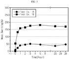
- the amorphous adhesive binder polymer has higher affinity with an electrolyte, as compared to the fluorinated binder polymer. Therefore, when using the adhesive binder polymer according to the present disclosure, it is possible to improve the output of a battery. See, the following Test Examples 1A and 1B.
- the content of the amorphous adhesive binder polymer is 50-84 parts by weight based on 100 parts by weight of the total binder polymer content.
- the content of the amorphous adhesive binder polymer may be 50-80 parts by weight, 55-80 parts by weight, or 55-70 parts by weight.
- the separator shows excessively high air permeability and causes separation of the coating layer during the injection of an electrolyte, and thus is not suitable as a separator for an electrochemical device.
- the content of the adhesive binder polymer is larger than 84 parts by weight, air permeability is low and a certain degree of adhesion is realized.
- the coating layer is separated during the injection of an electrolyte, and thus the separator is not suitable as a separator for an electrochemical device.
- the separator according to an embodiment of the present disclosure includes the amorphous adhesive binder polymer in an amount of 50-84 parts by weight, it has low air permeability, shows significantly high adhesion to an electrode and low resistance, and thus provides a separator suitable for an electrochemical device.
- the fluorinated binder polymer is not dissolved in an electrolyte so that it can retain a film shape, and shows phase transition property to form pores in the porous coating layer.
- the fluorinated binder polymer can prevent slurry for forming a porous coating layer from infiltrating into the pores of the porous substrate.
- the content of the fluorinated binder polymer is less than 15 parts by weight, pores in the porous coating layer are reduced and the slurry infiltrates to the porous substrate to cause pore blocking, resulting in the problem of an increase in air permeability.
- the amorphous binder polymer occupying a relatively larger proportion is swelled to cause separation of the porous coating layer.
- the amorphous adhesive binder polymer shows high binding force to the inorganic materials and has high affinity with an electrolyte.
- the amorphous adhesive binder polymer causes no phase separation when forming the porous coating layer, and thus forms no adhesive layer so that it may reduce the resistance of a separator.
- the content of the amorphous adhesive binder polymer is 50 parts by weight or more based on 100 parts by weight of the total content of porous polymers, no adhesive layer is formed, and thus it is possible to provide sufficient adhesion to an electrode as well as low resistance, preferably.
- the conventional separator including a fluorinated binder polymer alone as a binder polymer, it has air permeability similar to the air permeability of the separator according to an embodiment of the present disclosure, but it shows significantly high resistance and significantly low adhesion to an electrode.
- the content of the amorphous adhesive binder polymer is less than 50 parts by weight, it is possible to provide air permeability similar to or lower than the air permeability of the separator according to an embodiment of the present disclosure.
- adhesion to an electrode and resistance are merely slightly improved as compared to the conventional separator, but are not sufficient to attain a desired level according to the present disclosure.
- the fluorinated binder polymer may be a fluorinated copolymer.
- the fluorinated binder polymer may include polyvinylidene fluoride-co-hexafluoropropylene (PVdF-HFP), polyvinylidene fluoride-co-chlorotrifluoroethylene polyvinylidene fluoride-co-polytetrafluoroethylene (PVdF-PTFE), or a mixture of at least two of them.
- PVdF-HFP polyvinylidene fluoride-co-hexafluoropropylene
- PVdF-PTFE polyvinylidene fluoride-co-chlorotrifluoroethylene polyvinylidene fluoride-co-polytetrafluoroethylene
- the fluorinated binder polymer may include polyvinylidene fluoride-co-hexafluoropropylene (PVdF-HFP) and polyvinylidene fluoride-co-chlorotrifluoroethylene.
- the weight ratio of polyvinylidene fluoride-co-hexafluoropropylene (PVdF-HFP) to polyvinylidene fluoride-co-chlorotrifluoroethylene may be 90:10-50:50, 80:20-60:40, or 75:25-70:30.
- the inorganic particles there is no particular limitation in the inorganic particles, as long as they are electrochemically stable.
- the inorganic particles that may be used herein, as long as they cause no oxidation and/or reduction in the range (e.g. 0-5V based on Li/Li + ) of operating voltage of an applicable electrochemical device.
- the inorganic particles may be inorganic particles having a dielectric constant of 5 or more, inorganic particles having lithium ion transportability or a mixture thereof.
- the inorganic particles having a dielectric constant of 5 or more may include any one selected from the group consisting of Al 2 O 3 , SiO 2 , ZrO 2 , AlOOH, TiO 2 , BaTiO 3 , Pb(Zr x Ti 1-x )O 3 (PZT, wherein 0 ⁇ x ⁇ 1), Pb 1-x La x Zr 1-y Ti y O 3 (PLZT, wherein 0 ⁇ x ⁇ 1, 0 ⁇ y ⁇ 1), (1-x)Pb(Mg 1/3 Nb 2/3 )O 3 -xPbTiO 3 (PMN-PT, wherein 0 ⁇ x ⁇ 1), hafnia (HfO 2 ), SrTiO 3 , SnO 2 , CeO 2 , MgO, NiO, CaO, ZnO and SiC, or a mixture of two or more of them.
- the inorganic particles having lithium ion transportability may be any one selected from the group consisting of include lithium phosphate (Li 3 PO 4 ), lithium titanium phosphate (Li x Ti y (PO 4 ) 3 , 0 ⁇ x ⁇ 2, 0 ⁇ y ⁇ 3), lithium aluminum titanium phosphate (Li x Al y Ti z (PO 4 ) 3 , 0 ⁇ x ⁇ 2, 0 ⁇ y ⁇ 1, 0 ⁇ z ⁇ 3), (LiAlTiP) x O y -based glass (1 ⁇ x ⁇ 4, 0 ⁇ y ⁇ 13), lithium lanthanum titanate (Li x La y TiO 3 , 0 ⁇ x ⁇ 2, 0 ⁇ y ⁇ 3), lithium germanium thiophosphate (Li x Ge y P z S w , 0 ⁇ x ⁇ 4, 0 ⁇ y ⁇ 1, 0 ⁇ z ⁇
- the inorganic particles preferably have an average particle diameter of 0.001-10 ⁇ m, preferably 100-700 nm, and more preferably 150-600 nm, in order to form a coating layer with a uniform thickness and to provide suitable porosity.
- the weight ratio of the inorganic particles to the binder polymer may be 90:10-50:50.
- the weight ratio of the inorganic particles to the binder polymer satisfies the above-defined range, it is possible to prevent the problem of a decrease in pore size and porosity of the resultant coating layer, caused by an increase in content of the binder polymer. It is also possible to solve the problem of degradation of peeling resistance of the resultant coating layer, caused by a decrease in content of the binder polymer.
- the separator according to an embodiment of the present disclosure may further include other additives as ingredients of the porous coating layer, besides the above-described inorganic particles and binder polymers.
- the porous coating layer may have a thickness of 1-15 ⁇ m, particularly 1.5-10 ⁇ m.
- the porous coating layer preferably has a porosity of 35-85% but is not limited thereto.
- the porous polymer substrate may be a porous polymer film substrate or a porous polymer nonwoven web substrate.
- the porous polymer film substrate may be a porous polymer film including polyolefin, such as polyethylene or polypropylene. Such a polyolefin porous polymer film substrate may realize a shut-down function at a temperature of 80-150°C.
- the polyolefin porous polymer film may be formed of polymers including polyolefin polymers, such as polyethylene, including high-density polyethylene, linear low-density polyethylene, low-density polyethylene or ultrahigh-molecular weight polyethylene, polypropylene, polybutylene, or polypentene, alone or in combination of two or more of them.
- polyolefin polymers such as polyethylene, including high-density polyethylene, linear low-density polyethylene, low-density polyethylene or ultrahigh-molecular weight polyethylene, polypropylene, polybutylene, or polypentene, alone or in combination of two or more of them.
- the porous polymer film substrate may be obtained by molding various polymers, such as polyesters, other than polyolefins, into a film shape.
- the porous polymer film substrate may have a stacked structure of two or more film layers, wherein each film layer may be formed of polymers including the above-mentioned polymers, such as polyolefins or polyesters, alone or in combination of two or more of them.
- the porous polymer film substrate and porous nonwoven web substrate may be formed of polyethylene terephthalate, polybutylene terephthalate, polyester, polyacetal, polyamide, polycarbonate, polyimide, polyetherether ketone, polyether sulfone, polyphenylene oxide, polyphenylene sulfide, or polyethylene naphthalene, alone or in combination, besides the above-mentioned polyolefins
- the porous polymer substrate has a thickness of 1-100 ⁇ m, particularly 5-50 ⁇ m.
- the pore size and porosity may be 0.01-50 ⁇ m and 20-75%, respectively.
- the separator according to an embodiment of the present disclosure may be obtained by any conventional method known to those skilled in the art.
- the slurry for forming a porous coating layer may be prepared by dispersing the inorganic particles in polymer dispersion containing the binder polymers dispersed in a solvent, and then the slurry for forming a porous coating layer may be applied to a porous substrate, followed by drying, thereby forming a porous coating layer.
- non-limiting examples of the solvent include water, acetone, tetrahydrofuran, methylene chloride, chloroform, dimethyl formamide, N-methyl-2-pyrrolidone, methyl ethyl ketone and cyclohexane, or a mixture of two or more of them.
- a slot coating process includes coating a slurry supplied through a slot die onto the whole surface of a substrate and is capable of controlling the thickness of a coating layer depending on the flux supplied from a metering pump.
- dip coating includes dipping a substrate into a tank containing a slurry to carry out coating and is capable of controlling the thickness of a coating layer depending on the concentration of the slurry and the rate of removing the substrate from the slurry tank. Further, in order to control the coating thickness more precisely, it is possible to carry out post-metering through a Mayer bar or the like, after dipping.
- the porous substrate coated with the slurry for forming a porous coating layer is dried by using a dryer, such as an oven, thereby forming a porous coating layer on at least one surface of the porous substrate.
- the inorganic particles are bound among themselves by the binder polymer while they are packed and are in contact with each other.
- interstitial volumes are formed among the inorganic particles and the interstitial volumes become vacant spaces to form pores.
- the binder polymer attaches the inorganic particles to one another so that they may retain their binding states.
- the binder polymer connects and fixes the inorganic particles with each other.
- the pores of the porous coating layer are those formed by the interstitial volumes among the inorganic particles which become vacant spaces.
- the space may be defined by the inorganic particles facing each other substantially in a closely packed or densely packed structure of the inorganic particles.
- the drying step may be carried out in a drying chamber, wherein the drying chamber is not limited to a particular condition due to the application of a non-solvent.
- the porous coating layer is dried under a humidified condition.
- the porous coating layer may be formed at a temperature of 20-45°C, 20-35°C, or 20-30°C, under a relative humidity of 15-70%, 15-50%, or 30-45%.
- the binder polymers may be distributed homogeneously in the porous coating layer according to the present disclosure.
- an electrochemical device including a cathode, an anode and a separator interposed between the cathode and the anode, wherein the separator is the above-described separator according to an embodiment of the present disclosure.
- the electrochemical device includes any device which carries out electrochemical reaction, and particular examples thereof include all types of primary batteries, secondary batteries, fuel cells, solar cells or capacitors, such as super capacitor devices. Particularly, among the secondary batteries, lithium secondary batteries, including lithium metal secondary batteries, lithium ion secondary batteries, lithium polymer secondary batteries or lithium ion polymer batteries, are preferred.
- the cathode and the anode used in combination with the separator according to the present disclosure are not particularly limited, and may be obtained by allowing electrode active materials to be bound to an electrode current collector through a method generally known in the art.
- the electrode active materials include conventional cathode active materials that may be used for the cathodes for conventional electrochemical devices. Particularly, lithium manganese oxides, lithium cobalt oxides, lithium nickel oxides, lithium iron oxides or lithium composite oxides containing a combination thereof are used preferably.
- Non-limiting examples of an anode active material include conventional anode active materials that may be used for the anodes for conventional electrochemical devices.
- lithium-intercalating materials such as lithium metal or lithium alloys, carbon, petroleum coke, activated carbon, graphite or other carbonaceous materials
- a cathode current collector include foil made of aluminum, nickel or a combination thereof.
- an anode current collector include foil made of copper, gold, nickel, nickel alloys or a combination thereof.
- the electrolyte that may be used in the electrochemical device according to the present disclosure is a salt having a structure of A + B - , wherein A + includes an alkali metal cation such as Li + , Na + , K + or a combination thereof, and B - includes an anion such as PF 6 - , BF 4 - , Cl - , Br - , I - , ClO 4 - , AsF 6 - , CH 3 CO 2 - , CF 3 SO 3 - , N(CF 3 SO 2 ) 2 - , C(CF 2 SO 2 ) 3 - or a combination thereof, the salt being dissolved or dissociated in an organic solvent including propylene carbonate (PC), ethylene carbonate (EC), diethyl carbonate (DEC), dimethyl carbonate (DMC), dipropyl carbonate (DPC), dimethyl sulfoxide, acetonitrile, dimethoxyethane, diethoxyethane,
- Injection of the electrolyte may be carried out in an adequate step during the process for manufacturing a battery depending on the manufacturing process of a final product and properties required for a final product. In other words, injection of the electrolyte may be carried out before the assemblage of a battery or in the final step of the assemblage of a battery.
- LiNi 0 . 6 Co 0.2 Mn 0.2 O 2 as a cathode active material carbon black and polyvinylidene fluoride (PVdF) were introduced to N-methyl-2-pyrrolidone (NMP) at a weight ratio of 96:2:2 and mixed to obtain cathode slurry.
- NMP N-methyl-2-pyrrolidone
- the resultant cathode slurry was coated on aluminum foil (thickness 20 ⁇ m) as a cathode current collector with a capacity of 3.28 mAh/g to obtain a cathode.
- the binder polymer having the composition as shown in Table 1 was introduced to acetone as a solvent and dissolved therein at 50°C for about 4 hours to obtain a binder polymer solution.
- Alumina (Al 2 O 3 ) (particle size: 500 nm) and boehmite (AlO(OH)) (particle size: 250 nm) were introduced to the binder polymer solution as inorganic particles at a weight ratio of 9:1.
- the weight ratio of the binder polymer to the total inorganic particles was controlled to 1:4.
- cyanoethyl polyvinyl alcohol as a dispersing agent was added in an amount of 2 parts by weight based on the total content of the inorganic particles, and the inorganic particles were pulverized and dispersed by using a ball milling process for 12 hours to obtain slurry for forming a porous coating layer having a ratio of solvent to solid content of 4:1.
- the slurry for forming a porous coating layer was applied to both surfaces of a polyethylene porous film (porosity: 45%) at 23°C under a relative humidity of 40% to a total loading amount of 13.5 g/m 2 , followed by drying, thereby providing a separator having a porous coating layer formed thereon.
- the separator and the electrode were laminated in such a manner that the porous coating layer of the separator might face the anode active material layer of the electrode of 1), and pressing was carried out at 70°C under 600 kgf for 1 sec to obtain an electrode assembly including the anode laminated with the separator.
- Electrochemical devices were obtained in the same manner as Example 1, except that the content of binder polymer was controlled as shown in the following Table 1.
- Electrochemical devices were obtained in the same manner as Example 1, except that the content of binder polymer was controlled as shown in the following Table 1.
- Polyvinylidene fluoride-co-hexafluoropropylene was introduced to N-methyl-2-pyrrolidone (NMP) as a solvent and dissolved therein at 50°C for about 4 hours to obtain a binder polymer solution having a concentration of 20 wt%.
- NMP N-methyl-2-pyrrolidone
- the binder polymer solution was coated on a glass plate through a bar coating process to obtain a binder polymer film having a thickness of 50 ⁇ m. After drying the binder polymer film at 120°C, it was peeled off from the glass plate and vacuum-dried to remove the remaining solvent, and then cut into a diameter of 20 mm.
- the binder polymer film was dipped in ethyl methyl carbonate as a solvent and a change in film weight was observed as a function of dipping time. The results are shown in FIG. 3 .
- a binder film was obtained in the same manner as Test Example 1A, except that polyvinyl acetate was used as a binder polymer, instead of polyvinylidene fluoride-co-hexafluoropropylene, and the resultant binder polymer film was coated on a release agent-treated polyethylene terephthalate (PET) film so that it might be peeled off with ease
- PET polyethylene terephthalate
- the binder polymer film was dipped in ethyl methyl carbonate as a solvent and a change in film weight was observed as a function of dipping time. The results are shown in FIG. 3 .
- PVdF-CTFE PVAc (parts by weight) 70 70 70 55 80 0 100 16.5 : 45 90 Content of amorphous adhesive binder polymer based on 100 parts by weight of total binder polymer content (parts by weight) 70 70 70 55 80 0 100 45 90 Thickness ( ⁇ m) 16.6 17.0 17.0 17.5 16.9 18.2 17.8 17.2 18.5 Loading amount of slurry for forming porous coating layer (g/m 2 ) 13.5 13.7 13.6 14.1 13.8 13.7 13.7 13.3 13.9 Air permeability (sec/100mL) 688 722 612 471 726 764 1107 461 924 Lami Strength (gf/25mm) (at 70°C, 600kgf) 150 143
- An anode was obtained in the same manner as Example 1-1) and was cut into a size of 25 mm x 100 mm.
- Each of the separators according to Examples 1-5 and Comparative Examples 1-4 was cut into a size of 25 mm x 100 mm.
- the separator was stacked with the anode, and the stacked product was inserted between PET films having a thickness of 100 ⁇ m and adhered by using a flat press.
- the flat press was heated at 70°C under a pressure of 600 kgf for 1 second.
- the adhered separator and anode were attached to slide glass by using a double-sided tape.
- the end portion (10 mm or less from the end of the adhered surface) of the adhered separator was stripped off and attached to a 25 mm x 100 mm PET film by using a single-sided tape so that they might be connected in the longitudinal direction. Then, slide glass was mounted to the lower holder of a UTM instrument (LLOYD Instrument LF Plus), the PET film having the separator attached thereto was mounted to the upper holder of the UTM instrument, and force was applied at 180° and a rate of 300 mm/min. The force required for separating the anode from the porous coating layer facing the anode was measured.
- UTM instrument LLOYD Instrument LF Plus
- Each of the separators according to Examples 1-5 and Comparative Examples 1-4 was cut into a size of 15 mm X 100 mm.
- a double-sided adhesive tape was attached to a glass plate and the porous coating layer surface of the separator was attached to the adhesive tape.
- the end portion of the separator was mounted to a UTM instrument (LLOYD Instrument LF Plus), and force was applied at 180° and a rate of 300 mm/min. The force required for separating the porous coating layer from the porous polymer substrate was measured.
- the thickness of a separator was determined by using a thickness measuring instrument (Mitutoyo Co., VL-50S-B).
- the air permeability of each separator was determined by using a Gurley type air permeability tester according to JIS P-8117. Herein, the time required for 100 mL of air to pass through a diameter of 28.6 mm and an area of 645 mm 2 was measured.
- the resistance of each of the separators according to Examples 1-5 and Comparative Examples 1-4 was determined by dipping each separator in an electrolyte.
- 1M LiPF 6 dissolved in ethylene carbonate / ethylmethyl carbonate (weight ratio 3:7) was used as an electrolyte and the alternating current resistance was measured at 25°C.
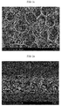
- FIGS. 1a-1c and FIGS. 2a-2c The results are shown in FIGS. 1a-1c and FIGS. 2a-2c .
- FIG. 1a to FIG.1c show scanning electron microscopic (SEM) images illustrating the section and the surface of the separator according to Comparative Example 1.
- FIG. 1a illustrates the section of the separator using a fluorinated binder polymer alone
- FIG. 1b is an enlarged view of FIG. 1a
- FIG. 1c show a SEM image illustrating the surface of the separator as shown in FIG. 1a .
- an adhesive layer is formed on a porous coating layer.
- the porous layer and the adhesive layer cause interfacial separation.
- FIG. 2a to FIG. 2c show SEM images illustrating the section and the surface of the separator according to Example 3.
- FIG. 2a illustrates the section of the separator using an amorphous adhesive binder polymer in combination with a fluorinated binder polymer
- FIG. 2b is an enlarged view of FIG. 2a
- FIG. 2c show a SEM image illustrating the surface of the separator as shown in FIG. 2a .
- the separator according to an embodiment of the present disclosure causes no separation between the porous coating layer and the adhesive layer.
- the binder polymer according to the present disclosure i.e. the amorphous adhesive binder polymer and the fluorinated binder polymer are distributed homogeneously in the thickness direction of the porous coating layer and no separate adhesive layer is formed.
Landscapes
- Chemical & Material Sciences (AREA)
- Chemical Kinetics & Catalysis (AREA)
- Electrochemistry (AREA)
- General Chemical & Material Sciences (AREA)
- Engineering & Computer Science (AREA)
- Power Engineering (AREA)
- Inorganic Chemistry (AREA)
- Manufacturing & Machinery (AREA)
- Materials Engineering (AREA)
- Microelectronics & Electronic Packaging (AREA)
- Composite Materials (AREA)
- Cell Separators (AREA)
- Electric Double-Layer Capacitors Or The Like (AREA)
Applications Claiming Priority (2)
| Application Number | Priority Date | Filing Date | Title |
|---|---|---|---|
| KR1020180114300A KR102311810B1 (ko) | 2018-09-21 | 2018-09-21 | 세퍼레이터 및 이를 포함하는 전기화학소자 |
| PCT/KR2019/012271 WO2020060310A1 (ko) | 2018-09-21 | 2019-09-20 | 세퍼레이터 및 이를 포함하는 전기화학소자 |
Publications (2)
| Publication Number | Publication Date |
|---|---|
| EP3734701A1 true EP3734701A1 (de) | 2020-11-04 |
| EP3734701A4 EP3734701A4 (de) | 2021-04-21 |
Family
ID=69887564
Family Applications (1)
| Application Number | Title | Priority Date | Filing Date |
|---|---|---|---|
| EP19862459.5A Pending EP3734701A4 (de) | 2018-09-21 | 2019-09-20 | Separator und elektrochemische vorrichtung damit |
Country Status (5)
| Country | Link |
|---|---|
| US (1) | US11784377B2 (de) |
| EP (1) | EP3734701A4 (de) |
| KR (1) | KR102311810B1 (de) |
| CN (2) | CN111418088A (de) |
| WO (1) | WO2020060310A1 (de) |
Families Citing this family (15)
| Publication number | Priority date | Publication date | Assignee | Title |
|---|---|---|---|---|
| JP7476339B2 (ja) * | 2020-04-06 | 2024-04-30 | エルジー エナジー ソリューション リミテッド | 電気化学素子用の分離膜及びその製造方法 |
| EP4135113A4 (de) * | 2020-04-14 | 2024-11-20 | LG Energy Solution, Ltd. | Separator für elektrochemische vorrichtung und verfahren zur herstellung davon |
| WO2022005211A1 (ko) * | 2020-06-30 | 2022-01-06 | 주식회사 엘지에너지솔루션 | 리튬 이차 전지용 분리막 및 이의 제조방법 및 이에 의해 제조된 분리막 |
| EP4152509B1 (de) | 2020-07-20 | 2025-11-12 | LG Energy Solution, Ltd. | Separator für sekundärbatterie, herstellungsverfahren dafür, verfahren zur herstellung einer sekundärbatterie mit dem separator und sekundärbatterie, die nach dem verfahren hergestellt ist |
| US20230327286A1 (en) * | 2020-09-18 | 2023-10-12 | Lg Energy Solution, Ltd. | Separator for electrochemical device and method for manufacturing the same |
| KR102865418B1 (ko) * | 2020-10-16 | 2025-09-26 | 주식회사 엘지에너지솔루션 | 리튬 이차 전지용 분리막 및 이의 제조방법 |
| US20230198094A1 (en) * | 2020-10-20 | 2023-06-22 | Lg Energy Solution, Ltd. | Separator and electrochemical device including the same |
| EP4156400A1 (de) | 2021-09-27 | 2023-03-29 | LG Energy Solution, Ltd. | Separator für sekundärbatterie |
| CN116868434A (zh) * | 2021-10-06 | 2023-10-10 | 株式会社Lg新能源 | 用于二次电池的隔板 |
| JP7754570B2 (ja) | 2021-10-06 | 2025-10-15 | エルジー エナジー ソリューション リミテッド | 二次電池用分離膜 |
| CN114824646B (zh) * | 2022-03-21 | 2024-07-05 | 惠州锂威电子科技有限公司 | 一种复合油基隔膜及其制备方法和二次电池 |
| EP4576392A4 (de) * | 2022-11-09 | 2025-09-03 | Lg Energy Solution Ltd | Separator, sekundärbatterie damit und verfahren zur herstellung einer sekundärbatterie |
| FR3155003A1 (fr) * | 2023-11-03 | 2025-05-09 | Arkema France | Composition comprenant un polymère fluoré et un copolymère acrylique et utilisation de celle-ci comme liant d’électrodes |
| WO2025231125A1 (en) * | 2024-05-01 | 2025-11-06 | Arkema Inc. | Coating compositions for separator membranes used in secondary batteries |
| WO2026035040A1 (ko) * | 2024-08-06 | 2026-02-12 | 주식회사 엘지에너지솔루션 | 리튬 이차전지용 분리막과 이의 제조 방법 및 이를 포함하는 리튬 이차전지과 이의 제조 방법 |
Family Cites Families (21)
| Publication number | Priority date | Publication date | Assignee | Title |
|---|---|---|---|---|
| JPS5777265A (en) * | 1980-10-30 | 1982-05-14 | Mitsubishi Agricult Mach Co Ltd | Device to adjust wheel distance of front wheels |
| KR100686816B1 (ko) | 2005-07-22 | 2007-02-26 | 삼성에스디아이 주식회사 | 리튬 이차 전지 |
| KR100727248B1 (ko) | 2007-02-05 | 2007-06-11 | 주식회사 엘지화학 | 다공성 활성층이 코팅된 유기/무기 복합 분리막 및 이를구비한 전기화학소자 |
| KR101040482B1 (ko) * | 2008-03-04 | 2011-06-09 | 주식회사 엘지화학 | 다공성 코팅층이 코팅된 세퍼레이터 및 이를 구비한 전기화학소자 |
| KR101740511B1 (ko) | 2012-02-15 | 2017-05-26 | 주식회사 엘지화학 | 다공성 코팅층이 형성된 세퍼레이터, 및 이를 포함하는 전기화학 소자 |
| US10096810B2 (en) | 2012-05-10 | 2018-10-09 | Samsung Sdi Co., Ltd. | Separator and method of manufacturing the same and rechargeable lithium battery including the same |
| KR101745631B1 (ko) | 2012-12-07 | 2017-06-09 | 주식회사 엘지화학 | 평균입경이 다른 무기물 입자의 이중 다공성 코팅층을 포함하는 이차전지용 분리막, 이를 포함하는 이차전지, 및 상기 분리막의 제조방법 |
| JP6289625B2 (ja) | 2013-10-31 | 2018-03-07 | エルジー・ケム・リミテッド | 有機−無機複合多孔性膜、これを含むセパレーター及び電極構造体 |
| KR20150106808A (ko) | 2013-11-21 | 2015-09-22 | 삼성에스디아이 주식회사 | 이차 전지 및 이의 제조 방법 |
| WO2015076574A1 (ko) * | 2013-11-21 | 2015-05-28 | 삼성에스디아이 주식회사 | 분리막 및 이를 이용한 이차 전지 |
| JP6382051B2 (ja) * | 2014-09-30 | 2018-08-29 | 旭化成株式会社 | 蓄電デバイス用セパレータ |
| KR20160061165A (ko) | 2014-11-21 | 2016-05-31 | 삼성에스디아이 주식회사 | 이차 전지용 세퍼레이터 및 이를 포함하는 이차 전지 |
| KR101742653B1 (ko) * | 2015-04-27 | 2017-06-01 | 삼성에스디아이 주식회사 | 높은 겔화 특성을 가진 아크릴계 공중합체를 포함하는 분리막 및 이를 포함하는 전기 화학 전지 |
| KR101742652B1 (ko) | 2015-04-27 | 2017-06-01 | 삼성에스디아이 주식회사 | 분리막 및 이를 포함하는 전기 화학 전지 |
| KR102121277B1 (ko) | 2015-05-11 | 2020-06-10 | 주식회사 엘지화학 | 유기/무기 복합 다공성 세퍼레이터 및 그를 포함하는 전기화학소자 |
| KR101751443B1 (ko) | 2015-10-13 | 2017-06-27 | 주식회사 엘지화학 | 다공성 코팅층을 구비한 세퍼레이터 및 이를 구비한 전기화학소자 |
| CN105406009A (zh) * | 2015-12-23 | 2016-03-16 | 梁百胜 | 一种凝胶黑芯锂离子电池及其制备方法 |
| CN108780866A (zh) | 2016-03-29 | 2018-11-09 | 东丽株式会社 | 二次电池用隔膜和二次电池 |
| KR102434168B1 (ko) * | 2016-09-21 | 2022-08-19 | 데이진 가부시키가이샤 | 비수계 이차 전지용 세퍼레이터 및 비수계 이차 전지 |
| EP3518318B1 (de) | 2017-02-13 | 2023-12-27 | LG Energy Solution, Ltd. | Trennfolie für lithiumsekundärbatterie mit klebeschicht |
| KR20180114300A (ko) | 2017-04-10 | 2018-10-18 | 한상근 | 잔재물 제거와 온도 및 전원제어 기능을 갖는 납땜장치 |
-
2018
- 2018-09-21 KR KR1020180114300A patent/KR102311810B1/ko active Active
-
2019
- 2019-09-20 EP EP19862459.5A patent/EP3734701A4/de active Pending
- 2019-09-20 WO PCT/KR2019/012271 patent/WO2020060310A1/ko not_active Ceased
- 2019-09-20 US US16/960,218 patent/US11784377B2/en active Active
- 2019-09-20 CN CN201980006117.1A patent/CN111418088A/zh active Pending
- 2019-09-20 CN CN202410808051.0A patent/CN118841711A/zh active Pending
Also Published As
| Publication number | Publication date |
|---|---|
| KR102311810B1 (ko) | 2021-10-08 |
| EP3734701A4 (de) | 2021-04-21 |
| CN118841711A (zh) | 2024-10-25 |
| WO2020060310A1 (ko) | 2020-03-26 |
| KR20200034470A (ko) | 2020-03-31 |
| CN111418088A (zh) | 2020-07-14 |
| US11784377B2 (en) | 2023-10-10 |
| US20210066692A1 (en) | 2021-03-04 |
Similar Documents
| Publication | Publication Date | Title |
|---|---|---|
| US11784377B2 (en) | Separator including porous coating layer with amorphous adhesive binder polymer and fluorinated binder polymer and electrochemical device including the same | |
| EP4102637B1 (de) | Separator für eine lithiumsekundärbatterie und herstellungsverfahren dafür | |
| EP2485296B1 (de) | Verfahren zur herstellung eines separators, in diesem verfahren hergestellter separator sowie verfahren zur herstellung einer elektronischen vorrichtung mit dem separator | |
| US12155088B2 (en) | Separator and electrochemical device containing the same | |
| EP3444866A1 (de) | Separator und elektrochemische vorrichtung damit | |
| US11699831B2 (en) | Separator and electrochemical device comprising same | |
| EP3694020B1 (de) | Separator für eine elektrochemische vorrichtung, herstellungsverfahren dafür und elektrochemische vorrichtung damit | |
| EP3734700A1 (de) | Separator und elektrochemische vorrichtung damit | |
| EP3579301A1 (de) | Separatorherstellungsverfahren, dadurch hergestellter separator und elektrochemisches element mit dem separator | |
| US12255352B2 (en) | Lithium secondary battery separator having enhanced adhesive strength to electrode and improved resistance characteristics, and lithium secondary battery comprising lithium secondary battery separator | |
| EP3553869B1 (de) | Elektrodenanordnung und elektrochemische vorrichtung mit der elektrodenanordnung | |
| EP3832756B1 (de) | Verfahren zur herstellung eines separators für eine elektrochemische vorrichtung | |
| US12438237B2 (en) | Battery cell and method for manufacturing the same | |
| KR20200143087A (ko) | 세퍼레이터 및 이를 포함하는 전기화학소자 | |
| EP4152507A1 (de) | Separator für lithiumsekundärbatterie und herstellungsverfahren dafür | |
| US20230178852A1 (en) | Method for manufacturing separator and separator obtained thereby | |
| EP4207468A1 (de) | Separator und elektrochemische vorrichtung damit | |
| EP4254636A1 (de) | Separator für elektrochemische vorrichtung sowie elektrodenanordnung und elektrochemische vorrichtung damit | |
| EP3761401B1 (de) | Separator für elektrochemische vorrichtung und verfahren zu seiner herstellung |
Legal Events
| Date | Code | Title | Description |
|---|---|---|---|
| STAA | Information on the status of an ep patent application or granted ep patent |
Free format text: STATUS: THE INTERNATIONAL PUBLICATION HAS BEEN MADE |
|
| PUAI | Public reference made under article 153(3) epc to a published international application that has entered the european phase |
Free format text: ORIGINAL CODE: 0009012 |
|
| STAA | Information on the status of an ep patent application or granted ep patent |
Free format text: STATUS: REQUEST FOR EXAMINATION WAS MADE |
|
| 17P | Request for examination filed |
Effective date: 20200728 |
|
| AK | Designated contracting states |
Kind code of ref document: A1 Designated state(s): AL AT BE BG CH CY CZ DE DK EE ES FI FR GB GR HR HU IE IS IT LI LT LU LV MC MK MT NL NO PL PT RO RS SE SI SK SM TR |
|
| AX | Request for extension of the european patent |
Extension state: BA ME |
|
| REG | Reference to a national code |
Ref country code: DE Ref legal event code: R079 Free format text: PREVIOUS MAIN CLASS: H01M0002160000 Ipc: H01M0010052000 |
|
| A4 | Supplementary search report drawn up and despatched |
Effective date: 20210319 |
|
| RIC1 | Information provided on ipc code assigned before grant |
Ipc: H01M 50/491 20210101ALI20210315BHEP Ipc: H01M 50/449 20210101ALI20210315BHEP Ipc: H01M 50/446 20210101ALI20210315BHEP Ipc: H01M 50/431 20210101ALI20210315BHEP Ipc: H01M 50/426 20210101ALI20210315BHEP Ipc: H01M 50/42 20210101ALI20210315BHEP Ipc: H01M 50/403 20210101ALI20210315BHEP Ipc: H01G 11/52 20130101ALI20210315BHEP Ipc: H01M 10/052 20100101AFI20210315BHEP |
|
| DAV | Request for validation of the european patent (deleted) | ||
| DAX | Request for extension of the european patent (deleted) | ||
| RAP1 | Party data changed (applicant data changed or rights of an application transferred) |
Owner name: LG ENERGY SOLUTION LTD. |
|
| RAP3 | Party data changed (applicant data changed or rights of an application transferred) |
Owner name: LG ENERGY SOLUTION, LTD. |
|
| STAA | Information on the status of an ep patent application or granted ep patent |
Free format text: STATUS: EXAMINATION IS IN PROGRESS |
|
| 17Q | First examination report despatched |
Effective date: 20231113 |