EP3734416A1 - Système de visiocasque capable d'indiquer une unité de suivi pour suivre ou non un geste de la main ou un mouvement de la main d'un utilisateur, procédé associé et support d'enregistrement lisible par ordinateur non transitoire associé - Google Patents
Système de visiocasque capable d'indiquer une unité de suivi pour suivre ou non un geste de la main ou un mouvement de la main d'un utilisateur, procédé associé et support d'enregistrement lisible par ordinateur non transitoire associé Download PDFInfo
- Publication number
- EP3734416A1 EP3734416A1 EP19171741.2A EP19171741A EP3734416A1 EP 3734416 A1 EP3734416 A1 EP 3734416A1 EP 19171741 A EP19171741 A EP 19171741A EP 3734416 A1 EP3734416 A1 EP 3734416A1
- Authority
- EP
- European Patent Office
- Prior art keywords
- state
- switch unit
- unit
- head mounted
- mounted display
- Prior art date
- Legal status (The legal status is an assumption and is not a legal conclusion. Google has not performed a legal analysis and makes no representation as to the accuracy of the status listed.)
- Withdrawn
Links
Images


Classifications
-
- G—PHYSICS
- G06—COMPUTING; CALCULATING OR COUNTING
- G06F—ELECTRIC DIGITAL DATA PROCESSING
- G06F3/00—Input arrangements for transferring data to be processed into a form capable of being handled by the computer; Output arrangements for transferring data from processing unit to output unit, e.g. interface arrangements
- G06F3/01—Input arrangements or combined input and output arrangements for interaction between user and computer
- G06F3/017—Gesture based interaction, e.g. based on a set of recognized hand gestures
-
- G—PHYSICS
- G06—COMPUTING; CALCULATING OR COUNTING
- G06F—ELECTRIC DIGITAL DATA PROCESSING
- G06F3/00—Input arrangements for transferring data to be processed into a form capable of being handled by the computer; Output arrangements for transferring data from processing unit to output unit, e.g. interface arrangements
- G06F3/01—Input arrangements or combined input and output arrangements for interaction between user and computer
- G06F3/011—Arrangements for interaction with the human body, e.g. for user immersion in virtual reality
- G06F3/012—Head tracking input arrangements
Definitions
- the present disclosure relates to a head mounted display system capable of indicating a tracking unit to track a hand gesture or a hand movement of a user or not, a related method and a related non-transitory computer readable storage medium according to the pre-characterizing clauses of claims 1, 8 and 13.
- a conventional display apparatus such as a head mounted display (HMD) usually includes a camera for capture environmental information.
- the camera is capable of being used as a tracking unit for tracking at least one of a hand gesture and a hand movement of a user, it consumes a lot of electricity for operation of the tracking unit.
- the tracking unit may provide an unexpected output based on an unexpected tracking result of the tracking unit, which brings inconvenience in use.
- the present disclosure aims at providing a head mounted display system capable of indicating a tracking unit to track a hand gesture or a hand movement of a user or not, a related method and a related non-transitory computer readable storage medium for saving power consumption and preventing an unexpected output generated by the tracking unit.
- a head mounted display system capable of indicating a tracking unit to track a hand gesture or a hand movement of a user or not, a related method and a related non-transitory computer readable storage medium according to the pre-characterizing clauses of claims 1, 8 and 13.
- the dependent claims pertain to corresponding further developments and improvements.
- the claimed head mounted display system includes a wearable body, a display unit, a tracking unit, a switch unit and a processing unit.
- the wearable body is configured to be worn by a user.
- the display unit is configured to display images to the user.
- the tracking unit is configured to track at least one of a hand gesture and a hand movement of the user in a first state or not to track the at least one of the hand gesture and the hand movement of the user in a second state.
- the switch unit is configured to generate an activating command when a state of the switch unit is changed.
- the processing unit is coupled to the tracking unit and the switch unit.
- the processing unit is configured to switch the tracking unit between the first state and the second state in response to the activating command generated by the switch unit.
- the claimed method of switching a tracking unit of a head mounted display system between a first state and a second state includes utilizing a switch unit of the head mounted display system to generate an activating command when a state of the switch unit is changed; and utilizing a processing unit of the head mounted display system to switch the tracking unit between the first state and the second state in response to the activating command.
- the tracking unit is configured to track at least one of a hand gesture and a hand movement of a user in the first state or not to track the at least one of the hand gesture and the hand movement of the user in the second state.
- the claimed non-transitory computer readable storage medium stores a program that causes the aforementioned head mounted display system to execute the aforementioned method.
- the present disclosure utilizes the switch unit to generate the activating command when the state of the switch unit is changed and further utilizes the processing unit to switch the tracking unit between the first state and the second state in response to the activating command. Therefore, it allows the user to enable or disable a hand tracking function of the tracking unit according to practical demands, which can save power consumption and prevent an unexpected output generated by the tracking unit due to an unexpected tracking result of the tracking unit.
- FIG. 1 is a diagram of a head mounted display system 1 according to a first embodiment of the present disclosure.
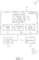
- FIG. 2 is a functional block diagram of the head mounted display system 1 according to the first embodiment of the present disclosure.
- the head mounted display system 1 includes a wearable body 11, which can be worn by a user, a display unit 12, a processing unit 13, a tracking unit 14 and a switch unit 15.
- the display unit 12 is configured to display images, such as images of a virtual environment, to the user.
- the display unit 12 can be mounted on the wearable body 11 and can be a liquid crystal display (LCD), light-emitting diode (LED) display, an organic light-emitting diode (OLED) display, or any other display.
- LCD liquid crystal display
- LED light-emitting diode
- OLED organic light-emitting diode
- the present disclosure is not limited thereto.
- the tracking unit 14 is configured to track at least one of a hand gesture and a hand movement of the user for providing interactive features.
- the tracking unit 14 can include a camera module 141 mounted on the wearable body 11, a hand sensor worn on a hand of the user, and a lower body sensor worn on a lower body of the user for tracking the hand gesture or the hand movement of the user.
- the present disclosure is not limited to this embodiment.
- the hand sensor and the lower body sensor can be omitted, and the tracking unit can only include the camera module.
- the switch unit 15 is configured to generate an activating command when a state of the switch unit 15 is changed.
- the switch unit 15 can include a physical button 151, and the state of the switch unit 15 can be changed when the physical button 151 is clicked.
- the present disclosure is not limited to this embodiment. In another embodiment, which will be described later, the state of the switch unit can be changed by other means.
- the processing unit 13 is coupled to the tracking unit 14 and the switch unit 15.
- the processing unit 13 is configured to switch the tracking unit 14 between a first state and a second state in response to the activating command generated by the switch unit 15.
- the processing unit 13 can be implemented in software, firmware, hardware configuration, or a combination thereof.
- the processing unit 13 can be a processor, such as a central processing unit, an application processor, a microprocessor, etc., which is mounted on the wearable body 11, or can be realized by an application specific integrated circuit (ASIC), which is mounted on the wearable body 11.
- ASIC application specific integrated circuit
- the display unit 12, the processing unit 13, the tracking unit 14 and the switch unit 15 are disposed on the wearable body 11.
- the head mounted display system further includes a remote computing apparatus disposed away from the wearable body separately and a communication module disposed on the wearable body for constructing a communication channel to the remote computing apparatus.
- the remote computing apparatus can be an edge computing device, a cloud computing device, a local host computer, a remote sever, a smartphone, or the like.
- the communication module can establish a wired connection or a wireless connection between elements on the wearable body and elements on the remote computing apparatus.
- the processing unit or the tracking unit can be at least partly disposed on the remote computing apparatus other than the wearable body and/or distributes part of the tasks to the remote computing apparatus, so that the tracking result of the tracking unit or the activating command can be transmitted between the remote computing apparatus and the wearable body via the communication module, so as to reduce the size and calculation of the wearable body, which makes the wearable body lightweight and portable.
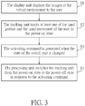
- FIG. 3 is a flow chart diagram illustrating a method of switching the tracking unit 14 of the head mounted display system 1 between the first state and the second state according to the first embodiment of the present disclosure. As shown in FIG. 3 , the method includes the following steps:
- steps S1 and S2 when the user wears the wearable body 11, the display unit 12 can display the images of the virtual environment to the user.
- the tracking unit 14 can be in the first state by default. At this moment, the tracking unit 14 can track at least one of the hand gesture and the hand movement of the user in the first state, so as to allow the user to interact with a virtual object of the virtual environment according to the tracking result of the tracking unit 14.
- steps S3 and S4 when it is desired to disable a hand tracking function of the tracking unit 14, the user can change the state of the switch unit 15 by clicking the physical button 151, e.g., the user can activate the switch unit 15 by clicking the physical button 151, so as to generate the activating command. Furthermore, the processing unit 13 switches the tracking unit 14 from the first state to the second state in response to the activating command, so that the tracking unit 14 does not track at least one of the hand gesture and the hand movement of the user in the second state, which can achieve a purpose of saving power consumption and preventing an unexpected output generated by the tracking unit 14 due to an unexpected tracking result of the tracking unit 14.
- the processing unit 13 can be configured to enable or disable the hand tracking function of the tracking unit 14 without interruption of other functions. However, it is not limited thereto. In another embodiment, the processing unit also can be configured to power on or power off the tracking unit. In other words, the first state can be a power-on state, and a second state can be a power-off state.
- the user can change the state of the switch unit 15 by clicking the physical button 151 again, e.g., the user can activate the switch unit 15 by clicking the physical button 151 again, so as to generate the activating command for indicating the processing unit 13 to switch the tracking unit 14 from the second state to the first state.
- FIG. 4 is a diagram of a head mounted display system 1' according to a second embodiment of the present disclosure.
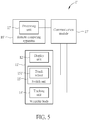
- FIG. 5 is a functional block diagram of the head mounted display system 1' according to the second embodiment of the present disclosure.
- the head mounted display system 1' includes a wearable body 11', a display unit 12', a processing unit 13', a tracking unit 14', a switch unit 15', a remote computing apparatus 16' and a communication module 17'.
- the structures and the configurations of the wearable body 11' and the display 12' of this embodiment are similar to the ones of the wearable body 11 and the display unit 12 of the first embodiment.
- the tracking unit 14' of this embodiment includes a camera module 141' mounted on the wearable body 11'.
- the processing unit 13' of this embodiment is configured on the remote computing apparatus 16' and coupled to the switch unit 15' and the tracking unit 14' by the communication module 17'.
- the switch unit 15' of this embodiment includes a touch sensor 151' mounted on the wearable body 11', and the state of the switch unit 15' is changed when the touch sensor 151' is double tapped.
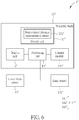
- FIG. 6 is a functional block diagram of a head mounted display system 1" according to a third embodiment of the present disclosure.
- the head mounted display system 1" includes a wearable body 11", a display unit 12", a processing unit 13", a tracking unit 14" and a switch unit 15".
- the structures and the configurations of the wearable body 11", the display 12" and the tracking unit 14" of this embodiment are similar to the ones of the wearable body 11 and the display unit 12 of the first embodiment. Detailed description is omitted herein.
- the switch unit 15" of this embodiment includes a non-contact distance measurement sensor 151", and the state of the switch unit 15" is changed when a measuring result of the non-contact distance measurement sensor 151" meets a predetermined condition.
- the non-contact distance measurement sensor 151" can measure a distance between the non-contact distance measurement sensor and a hand of the user in a non-contact manner, as a proximity switch, and the predetermined condition can refer to a predetermined distance.
- the switch unit 15" can generate the activating command.
- the non-contact distance measurement sensor 151" can include an infrared sensor.
- the present disclosure is not limited thereto.
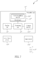
- FIG. 7 is a functional block diagram of a head mounted display system 1'" according to a fourth embodiment of the present disclosure.
- the head mounted display system 1'" includes a wearable body 11"', a display unit 12"', a processing unit 13"', a tracking unit 14'" and a switch unit 15'".
- the structures and the configurations of the wearable body 11'", the display 12'" and the tracking unit 14'" of this embodiment are similar to the ones of the wearable body 11 and the display unit 12 of the first embodiment. Detailed description is omitted herein.
- the switch unit 15'" includes a voice recognition module 151"', and the state of the switch unit 15'" is changed when a recognizing result of the voice recognition module 151'" meets a predetermined condition.
- the voice recognition module 151'" can recognize a voice command of the user, and the predetermined condition can refer to a predetermined voice command.
- the switch unit 15'" can generate the activating command.
- the voice recognition module 151'" can include a microphone. However, it is not limited thereto.
- the above-described embodiments of the present disclosure can be implemented in software, firmware, hardware configuration, or combination thereof, and it is also possible to provide a non-transitory computer readable storage medium for storing a program that causes a head mounted display system to execute any one of the aforementioned methods by a processor.
- the processor can be a central processing unit, an application processor, a microprocessor, etc., or may be realized by an application specific integrated circuit (ASIC).
- the computer-readable recording medium can be a Read-Only Memory (ROM), a random-access memory (RAM), a CD-ROM, a magnetic tape, a floppy disk, or an optical data storage device.
- ROM Read-Only Memory
- RAM random-access memory
- CD-ROM Compact Disk Read-Read Only Memory
- magnetic tape a magnetic tape
- a floppy disk or an optical data storage device.
- optical data storage device optical data storage device
- the present disclosure utilizes the switch unit to generate the activating command when the state of the switch unit is changed and further utilizes the processing unit to switch the tracking unit between the first state and the second state in response to the activating command. Therefore, it allows the user to enable or disable the hand tracking function of the tracking unit according to practical demands, which can save power consumption and prevent an unexpected output generated by the tracking unit due to an unexpected tracking result of the tracking unit.
Landscapes
- Engineering & Computer Science (AREA)
- General Engineering & Computer Science (AREA)
- Theoretical Computer Science (AREA)
- Human Computer Interaction (AREA)
- Physics & Mathematics (AREA)
- General Physics & Mathematics (AREA)
- User Interface Of Digital Computer (AREA)
Priority Applications (1)
| Application Number | Priority Date | Filing Date | Title |
|---|---|---|---|
| EP19171741.2A EP3734416A1 (fr) | 2019-04-30 | 2019-04-30 | Système de visiocasque capable d'indiquer une unité de suivi pour suivre ou non un geste de la main ou un mouvement de la main d'un utilisateur, procédé associé et support d'enregistrement lisible par ordinateur non transitoire associé |
Applications Claiming Priority (1)
| Application Number | Priority Date | Filing Date | Title |
|---|---|---|---|
| EP19171741.2A EP3734416A1 (fr) | 2019-04-30 | 2019-04-30 | Système de visiocasque capable d'indiquer une unité de suivi pour suivre ou non un geste de la main ou un mouvement de la main d'un utilisateur, procédé associé et support d'enregistrement lisible par ordinateur non transitoire associé |
Publications (1)
| Publication Number | Publication Date |
|---|---|
| EP3734416A1 true EP3734416A1 (fr) | 2020-11-04 |
Family
ID=66334247
Family Applications (1)
| Application Number | Title | Priority Date | Filing Date |
|---|---|---|---|
| EP19171741.2A Withdrawn EP3734416A1 (fr) | 2019-04-30 | 2019-04-30 | Système de visiocasque capable d'indiquer une unité de suivi pour suivre ou non un geste de la main ou un mouvement de la main d'un utilisateur, procédé associé et support d'enregistrement lisible par ordinateur non transitoire associé |
Country Status (1)
| Country | Link |
|---|---|
| EP (1) | EP3734416A1 (fr) |
Citations (9)
| Publication number | Priority date | Publication date | Assignee | Title |
|---|---|---|---|---|
| US20060136846A1 (en) * | 2004-12-20 | 2006-06-22 | Sung-Ho Im | User interface apparatus using hand gesture recognition and method thereof |
| US20100079356A1 (en) * | 2008-09-30 | 2010-04-01 | Apple Inc. | Head-mounted display apparatus for retaining a portable electronic device with display |
| US20140092011A1 (en) * | 2012-09-28 | 2014-04-03 | Movea | Remote control with 3d pointing and gesture recognition capabilities |
| US20150290031A1 (en) * | 2013-05-16 | 2015-10-15 | Wavelight Gmbh | Touchless user interface for ophthalmic devices |
| US20170109936A1 (en) * | 2015-10-20 | 2017-04-20 | Magic Leap, Inc. | Selecting virtual objects in a three-dimensional space |
| US20170227779A1 (en) * | 2014-09-30 | 2017-08-10 | Konica Minolta, Inc. | Head Mounted Display And Wearable Computer |
| US20170308158A1 (en) * | 2014-10-22 | 2017-10-26 | Sony Interactive Entertainment Inc. | Head mounted display, mobile information terminal, image processing apparatus, display control program, display control method, and display system |
| US20170322622A1 (en) * | 2016-05-09 | 2017-11-09 | Lg Electronics Inc. | Head mounted display device and method for controlling the same |
| US20170345400A1 (en) * | 2016-05-27 | 2017-11-30 | Beijing Pico Technology Co., Ltd. | Method of vision correction in a virtual reality environment |
-
2019
- 2019-04-30 EP EP19171741.2A patent/EP3734416A1/fr not_active Withdrawn
Patent Citations (9)
| Publication number | Priority date | Publication date | Assignee | Title |
|---|---|---|---|---|
| US20060136846A1 (en) * | 2004-12-20 | 2006-06-22 | Sung-Ho Im | User interface apparatus using hand gesture recognition and method thereof |
| US20100079356A1 (en) * | 2008-09-30 | 2010-04-01 | Apple Inc. | Head-mounted display apparatus for retaining a portable electronic device with display |
| US20140092011A1 (en) * | 2012-09-28 | 2014-04-03 | Movea | Remote control with 3d pointing and gesture recognition capabilities |
| US20150290031A1 (en) * | 2013-05-16 | 2015-10-15 | Wavelight Gmbh | Touchless user interface for ophthalmic devices |
| US20170227779A1 (en) * | 2014-09-30 | 2017-08-10 | Konica Minolta, Inc. | Head Mounted Display And Wearable Computer |
| US20170308158A1 (en) * | 2014-10-22 | 2017-10-26 | Sony Interactive Entertainment Inc. | Head mounted display, mobile information terminal, image processing apparatus, display control program, display control method, and display system |
| US20170109936A1 (en) * | 2015-10-20 | 2017-04-20 | Magic Leap, Inc. | Selecting virtual objects in a three-dimensional space |
| US20170322622A1 (en) * | 2016-05-09 | 2017-11-09 | Lg Electronics Inc. | Head mounted display device and method for controlling the same |
| US20170345400A1 (en) * | 2016-05-27 | 2017-11-30 | Beijing Pico Technology Co., Ltd. | Method of vision correction in a virtual reality environment |
Similar Documents
| Publication | Publication Date | Title |
|---|---|---|
| EP3164785B1 (fr) | Commande d'interface utilisateur de dispositif vestimentaire | |
| US10862595B2 (en) | Method for processing radio frequency interference, and electronic device | |
| EP2708983B9 (fr) | Procédé d'auto-commutation d'interface utilisateur d'un dispositif terminal portatif et son dispositif terminal portatif | |
| US11720182B2 (en) | Key indication method and electronic device | |
| US9329661B2 (en) | Information processing method and electronic device | |
| US11275456B2 (en) | Finger-wearable input assembly for controlling an electronic device | |
| KR102389063B1 (ko) | 햅틱 피드백을 제공하는 방법 및 이를 수행하는 전자 장치 | |
| CN110187822B (zh) | 一种终端及应用于终端的屏幕显示控制方法 | |
| US11545061B2 (en) | Electronic device for displaying screen through display in low-power mode and operating method thereof | |
| US20150109200A1 (en) | Identifying gestures corresponding to functions | |
| EP4203239A1 (fr) | Composant de dispositif électronique et procédé de commande associé, appareil de commande pour un dispositif électronique | |
| CN111025889A (zh) | 一种可穿戴设备及控制方法 | |
| EP2605108A1 (fr) | Dispositif de télécommande multipoint distant et système | |
| KR102518404B1 (ko) | 전자 장치 및 그의 시선 정보를 이용한 컨텐트 실행 방법 | |
| US20200326765A1 (en) | Head mounted display system capable of indicating a tracking unit to track a hand gesture or a hand movement of a user or not, related method and related non-transitory computer readable storage medium | |
| KR20170032050A (ko) | 젠더 모듈 및 젠더 모듈과 연동하는 단말기기의 동작방법 | |
| US9075575B2 (en) | Multimedia device having detachable controller functioning as remote control while detached | |
| US20200327867A1 (en) | Head mounted display system capable of displaying a virtual scene and a map of a real environment in a picture-in-picture mode, related method and related non-transitory computer readable storage medium | |
| CN111930509A (zh) | 智能眼镜的数据处理方法、装置、存储介质及电子设备 | |
| EP3734416A1 (fr) | Système de visiocasque capable d'indiquer une unité de suivi pour suivre ou non un geste de la main ou un mouvement de la main d'un utilisateur, procédé associé et support d'enregistrement lisible par ordinateur non transitoire associé | |
| KR102463080B1 (ko) | 머리 착용형 디스플레이 장치 및 머리 착용형 디스플레이 장치의 콘텐트 표시방법 | |
| KR20170086464A (ko) | 웨어러블 디바이스 및 그 제어 방법 | |
| US10992926B2 (en) | Head mounted display system capable of displaying a virtual scene and a real scene in a picture-in-picture mode, related method and related non-transitory computer readable storage medium | |
| KR102353919B1 (ko) | 터치의 압력에 응답하여 지정된 동작을 수행하는 전자 장치 및 방법 | |
| US20240061530A1 (en) | Spurious hand signal rejection during stylus use |
Legal Events
| Date | Code | Title | Description |
|---|---|---|---|
| PUAI | Public reference made under article 153(3) epc to a published international application that has entered the european phase |
Free format text: ORIGINAL CODE: 0009012 |
|
| STAA | Information on the status of an ep patent application or granted ep patent |
Free format text: STATUS: THE APPLICATION HAS BEEN PUBLISHED |
|
| AK | Designated contracting states |
Kind code of ref document: A1 Designated state(s): AL AT BE BG CH CY CZ DE DK EE ES FI FR GB GR HR HU IE IS IT LI LT LU LV MC MK MT NL NO PL PT RO RS SE SI SK SM TR |
|
| AX | Request for extension of the european patent |
Extension state: BA ME |
|
| STAA | Information on the status of an ep patent application or granted ep patent |
Free format text: STATUS: THE APPLICATION IS DEEMED TO BE WITHDRAWN |
|
| 18D | Application deemed to be withdrawn |
Effective date: 20210505 |