EP3734246A1 - Load sensor and multi-axis actuator integrated with load sensor - Google Patents
Load sensor and multi-axis actuator integrated with load sensor Download PDFInfo
- Publication number
- EP3734246A1 EP3734246A1 EP18893561.3A EP18893561A EP3734246A1 EP 3734246 A1 EP3734246 A1 EP 3734246A1 EP 18893561 A EP18893561 A EP 18893561A EP 3734246 A1 EP3734246 A1 EP 3734246A1
- Authority
- EP
- European Patent Office
- Prior art keywords
- shaft
- coupling part
- drive rod
- load sensor
- coupling
- Prior art date
- Legal status (The legal status is an assumption and is not a legal conclusion. Google has not performed a legal analysis and makes no representation as to the accuracy of the status listed.)
- Granted
Links
Images




Classifications
-
- G—PHYSICS
- G01—MEASURING; TESTING
- G01L—MEASURING FORCE, STRESS, TORQUE, WORK, MECHANICAL POWER, MECHANICAL EFFICIENCY, OR FLUID PRESSURE
- G01L5/00—Apparatus for, or methods of, measuring force, work, mechanical power, or torque, specially adapted for specific purposes
- G01L5/0061—Force sensors associated with industrial machines or actuators
- G01L5/0076—Force sensors associated with manufacturing machines
- G01L5/009—Force sensors associated with material gripping devices
-
- G—PHYSICS
- G01—MEASURING; TESTING
- G01L—MEASURING FORCE, STRESS, TORQUE, WORK, MECHANICAL POWER, MECHANICAL EFFICIENCY, OR FLUID PRESSURE
- G01L1/00—Measuring force or stress, in general
- G01L1/20—Measuring force or stress, in general by measuring variations in ohmic resistance of solid materials or of electrically-conductive fluids; by making use of electrokinetic cells, i.e. liquid-containing cells wherein an electrical potential is produced or varied upon the application of stress
- G01L1/22—Measuring force or stress, in general by measuring variations in ohmic resistance of solid materials or of electrically-conductive fluids; by making use of electrokinetic cells, i.e. liquid-containing cells wherein an electrical potential is produced or varied upon the application of stress using resistance strain gauges
- G01L1/2206—Special supports with preselected places to mount the resistance strain gauges; Mounting of supports
-
- G—PHYSICS
- G01—MEASURING; TESTING
- G01L—MEASURING FORCE, STRESS, TORQUE, WORK, MECHANICAL POWER, MECHANICAL EFFICIENCY, OR FLUID PRESSURE
- G01L1/00—Measuring force or stress, in general
- G01L1/20—Measuring force or stress, in general by measuring variations in ohmic resistance of solid materials or of electrically-conductive fluids; by making use of electrokinetic cells, i.e. liquid-containing cells wherein an electrical potential is produced or varied upon the application of stress
- G01L1/22—Measuring force or stress, in general by measuring variations in ohmic resistance of solid materials or of electrically-conductive fluids; by making use of electrokinetic cells, i.e. liquid-containing cells wherein an electrical potential is produced or varied upon the application of stress using resistance strain gauges
- G01L1/2287—Measuring force or stress, in general by measuring variations in ohmic resistance of solid materials or of electrically-conductive fluids; by making use of electrokinetic cells, i.e. liquid-containing cells wherein an electrical potential is produced or varied upon the application of stress using resistance strain gauges constructional details of the strain gauges
-
- H—ELECTRICITY
- H05—ELECTRIC TECHNIQUES NOT OTHERWISE PROVIDED FOR
- H05K—PRINTED CIRCUITS; CASINGS OR CONSTRUCTIONAL DETAILS OF ELECTRIC APPARATUS; MANUFACTURE OF ASSEMBLAGES OF ELECTRICAL COMPONENTS
- H05K13/00—Apparatus or processes specially adapted for manufacturing or adjusting assemblages of electric components
- H05K13/04—Mounting of components, e.g. of leadless components
Definitions
- the present invention relates to a load sensor and a load sensor integrated type multiaxial actuator, and, for example, relates to a load sensor that detects, in a multiaxial actuator to be used as a chip mounter that mounts an electronic part (chip) to a substrate, pressing force (load) to the chip in a case where the chip is suctioned and mounted to the substrate in a state where the chip is pressed against a tip end of a shaft-like member formed to be hollow, and a load sensor integrated type multiaxial actuator.
- This linear motor actuator is configured to cause a shaft-like member to perform linear motion in an axial direction by using a linear motor that can obtain linear thrust (For example, see Patent Literature 1).
- Patent Literature 1 Japanese Patent Application Publication No. 2014-18072
- a load sensor is a load sensor to be used for a multiaxial actuator that has a first shaft-like member that linearly moves in an axial direction in a state of being contained in a housing, and a second shaft-like member that is arranged in parallel with the first shaft-like member, linearly moves at the same time as the first shaft-like member in the axial direction, and has a tip end portion to be pressed, when a predetermined object is to be suctioned, against the object
- the load sensor including a coupling member that couples the first shaft-like member and the second shaft-like member, in which the coupling member has a first coupling part that couples the first shaft-like member, and a second coupling part that couples the second shaft-like member in an integrated state, and the first coupling part has a strain body part that is formed to be thinner than the second coupling part and supports the first shaft-like member, and a strain gauge attached to the strain body part.
- the strain gauge it is preferable to affix the strain gauge to a stress generation area where stress is generated when the tip end portion of the second shaft-like member is pressed against the object in the strain body part.
- the first coupling part it is preferable for the first coupling part to have a coated part where the strain gauge is coated with a predetermined coating material.
- a load sensor integrated type multiaxial actuator includes a first shaft-like member that linearly moves in an axial direction in a state of being contained in a housing, a second shaft-like member that is arranged in parallel with the first shaft-like member, linearly moves at the same time as the first shaft-like member in the axial direction, and has a tip end portion to be pressed, when a predetermined object is to be suctioned, against the object, and a coupling member that couples the first shaft-like member and the second shaft-like member to cause the first shaft-like member and the second shaft-like member to linearly move at the same time in the axial direction, in which the coupling member has a first coupling part that couples the first shaft-like member, and a second coupling part that couples the second shaft-like member, and the first coupling part has a strain body part that is formed to be thinner than the second coupling part and supports the first shaft-like member, and a strain gauge attached to the strain body part.
- the load sensor that may precisely detect the load of the pressing force to the object, and the load sensor integrated type multiaxial actuator.
- Fig. 1 is an external perspective view showing an entire configuration of a load sensor integrated type multiaxial actuator according to an embodiment of the present invention.
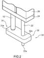
- Fig. 2 is a schematic partially expanded perspective view showing an external configuration of a coupling member according to the embodiment of the present invention.
- Fig. 3 is a schematic partially expanded perspective view showing a cross sectional configuration of the coupling member according to the embodiment of the present invention.
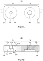
- Figs. 4 are a plan view and a cross sectional view showing a configuration of the coupling member according to the embodiment of the present invention.
- Figs. 1 is an external perspective view showing an entire configuration of a load sensor integrated type multiaxial actuator according to an embodiment of the present invention.
- Fig. 2 is a schematic partially expanded perspective view showing an external configuration of a coupling member according to the embodiment of the present invention.
- Fig. 3 is a schematic partially expanded perspective view showing a cross sectional configuration of the coupling member according to the embodiment of the present invention.
- Figs. 4 are a plan view and
- FIG. 5 are a schematic perspective view and a cross sectional view showing a state where a first coupling part of the coupling member is warped according to the embodiment of the present invention.
- Figs. 6 are plan views showing an arrangement of strain gauges affixed to the first coupling part of the coupling member according to the embodiment of the present invention.
- a load sensor integrated type multiaxial actuator 10 is used by being incorporated in a chip mounter that mounts an object such as an electronic part (chip) onto a substrate.
- the load sensor integrated type multiaxial actuator 10 mainly includes, for example, a housing 11 having a three-phase motor (not shown) built therein, a drive rod 12 serving as a first shaft-like member that linearly moves relatively in an axial direction by the three-phase motor, a suction rod 22 that is arranged in parallel with the drive rod 12 and serves as a second shaft-like member that suctions the chip at a tip end, and a coupling member 30 that integrally couples the drive rod 12 and the suction rod 22 on a tip end side and also serves as a load sensor that can detect a load when the chip is pressed against a tip end of the suction rod 22.
- the housing 11 is a package that has the above-mentioned three-phase motor built therein and is made of a metal, resin, or the like, and holds the drive rod 12 in a state where the drive rod 12 is allowed to linearly move relatively along the axial direction. It is noted that the housing 11 holds the drive rod 12 via a holding plate 24 (which will be described below).
- a three-phase coil (not shown) constituted by a U phase, a V phase, and a W phase is arranged in the surrounding of the drive rod 12, and when a current flows through the three-phase coil, the drive rod 12 linearly moves in the axial direction relative to the housing 11.
- the drive rod 12 is a columnar bar-like member made of a metal, resin, or the like extending along the axial direction, and linearly moves in a predetermined stroke range in a state of being held in the housing 11 via the holding plate 24.
- the drive rod 12 has a recessed part that has a predetermined diameter and a predetermined depth and is formed from an end face of a tip end portion 12a towards the axial direction, and a female screw part 12m ( Fig. 3 ) is formed on an inner peripheral surface thereof.
- the suction rod 22 is a hollow cylindrical member made of a metal, resin, or the like extending along the axial direction, and is arranged in parallel with the drive rod 12, in which when the chip is to be suctioned, a tip end portion 22a is to be pressed against the chip.
- the suction rod 22 is attached to a casing 26 via the holding plate 24.
- An external diameter of the suction rod 22 has dimension according to a size of the chip, and is smaller than the drive rod 12.
- the configuration is not limited to this, and the external diameter of the suction rod 22 may be larger than an external diameter of the drive rod 12, and may also be substantially the same.
- This suction rod 22 is connected to a vacuum pump or the like that is not shown in the drawing via a hose or the like.
- a suction pad (not shown) configured to suction the chip may be attached to the tip end portion 22a of the suction rod 22.
- the casing 26 is made of a metal, resin, or the like in which a through hole 26a supports such that the suction rod 22 can freely move relatively in the axial direction is formed, and supports such that the suction rod 22 can move in the axial direction along with the motion of the drive rod 12 in the axial direction.
- the holding plate 24 has a cuboid shape which is made of a metal, resin, or the like, and is integrally attached to both the housing 11 and the casing 26.
- the holding plate 24 supports such that the drive rod 12 and the suction rod 22 can move in the axial direction, and also suppresses turning of the suction rod 22 about the drive rod 12 in a state where a mutual positional relationship is held.
- the coupling member 30 is a plate-like member having a substantially cuboid shape which couples and fixes the tip end portion of the drive rod 12 and the tip end portion of the suction rod 22 and is made of a metal, resin, or the like.
- the coupling member 30 prevents the drive rod 12 from relatively moving in the axial direction relative to the coupling member 30, and also prevents the suction rod 22 from relatively moving in the axial direction relative to the coupling member 30.
- the coupling member 30 has a drive rod coupling part 31 serving as a first coupling part that integrally couples and supports in a state where the end face of the tip end portion 12a of the drive rod 12 and a front surface 31a are abutted each other, and a suction rod coupling part 32 serving as a second coupling part that integrally couples and supports in a state where the suction rod 22 penetrates from a front surface 32a to a rear surface 32b.
- the drive rod coupling part 31 is a part of the coupling member 30 on one side which is located on an extended line of the axial direction of the drive rod 12, and the suction rod coupling part 32 is a part of the coupling member 30 on another side on an extended line of the axial direction of the suction rod 22. That is, the coupling member 30 is formed as a single rigid body in which the drive rod coupling part 31 and the suction rod coupling part 32 are integrated with each other. This coupling member 30 can be formed by injection molding or cutting.
- the drive rod coupling part 31 and the suction rod coupling part 32 of the coupling member 30 are not actually separated from each other by a boundary between them, but are functional parts virtually divided into two substantially at a center of the coupling member 30.
- the shape is not limited to the substantially cuboid shape.
- the coupling member 30 may have a substantially cubic shape, or may also have a substantially circular shape in plan view or a substantially oval shape in plan view which has a predetermined thickness.
- a recessed part space 310 is formed on a rear surface 31b on an opposite side to the drive rod 12 in an area opposite to the drive rod 12.
- the recessed part space 310 of the drive rod coupling part 31 is a space that has a substantially rectangular shape in plan view or a substantially circular shape in plan view and is also formed to be recessed along the axial direction from the rear surface 31b.
- the drive rod coupling part 31 has a thin-plate like top wall part 311 thinner than the suction rod coupling part 32, and the top wall part 311 has a possibility of being more easily warped than other parts. That is, the top wall part 311 of the drive rod coupling part 31 becomes a part functioning as a strain body in the coupling member 30.
- a bottom surface 311b of the top wall part 311 opposite to the drive rod 12 is a region to which strain gauges 41 to 44 which will be described below are affixed, and is covered by a coating material 317 ( Fig. 3 ) of silicone corresponding to the strain gauges 41 to 44. Accordingly, it is possible to improve dust preventing property and rust preventing property for the strain gauges 41 to 44.
- the drive rod coupling part 31 has a boss part 312 protruding towards an opening of the recessed part space 310 in a center of the bottom surface 311b of the top wall part 311.
- a through hole 312h that is shaped to be cylindrical having such a length not to protrude from the rear surface 31b of the drive rod coupling part 31, and also has a predetermined inner diameter is formed.
- a bolt 315 is inserted into the through hole 312h of the boss part 312 to couple the drive rod 12 and the drive rod coupling part 31, and a male screw part of the bolt 315 and the female screw part 12m corresponding to a hole having a predetermined depth which is formed at the tip end portion 12a of the drive rod 12 are screwed together.
- the drive rod 12 is integrally coupled to the drive rod coupling part 31 and supported in a state where the tip end portion 12a is abutted against the front surface 31a of the drive rod coupling part 31. Accordingly, relative motion of the drive rod 12 in the axial direction relative to the coupling member 30 is suppressed.
- a through hole 32h that has a female screw part to be screwed with a male screw part provided on an outer peripheral surface corresponding to a part of a tip end side of the suction rod 22 is formed on an inner peripheral surface.
- the through hole 32h penetrates from the front surface 32a to the rear surface 32b.
- the suction rod 22 is integrally coupled to the suction rod coupling part 32 and supported, and relative motion in the axial direction relative to the coupling member 30 is suppressed.
- the strain gauges 41 to 44 are affixed to most strongly warped parts d1 and d2 when the load applied to the suction rod coupling part 32 is transmitted to the drive rod coupling part 31.
- an entire shape based on the warped parts in the top wall part 311 of the drive rod coupling part 31 becomes a substantially S-letter shape in cross section, and the most strongly warped parts d1 and d2 are parts where the front surface 31a of the drive rod coupling part 31 is bent the most, and are stress generation areas more substantially warped than a flat part d3 where bending is less.
- the strain gauges 41 to 44 use a change of resistance values when internally arranged resistance elements expand or contract together with a warp (distortion) generated at the top wall part 311 of the drive rod coupling part 31, and the so-called bridge circuit is constituted.
- the bridge circuit it is possible to measure a load according to the warp (distortion) on the basis of a change of a voltage caused by the resistance elements of the strain gauges 41 to 44.
- the suction rod 22 in conjunction with pressing-down of the drive rod 12, the suction rod 22 is pressed down together with the coupling member 30, and when the tip end portion 22a of the suction rod 22 is pressed against the chip, reactive force (load) from the chip to the suction rod coupling part 32 becomes a load to the drive rod coupling part 31 to be transmitted.
- the strain gauges 41 to 44 are previously affixed to the most strongly warped parts (deformed parts) d1 and d2 in the top wall part 311.
- These warped parts d1 and d2 are parts of the top wall part 311 of the drive rod coupling part 31 having a wall thickness thinner than the suction rod coupling part 32, and function as strain body parts.
- strain gauges 41 to 44 are affixed to the warped parts (deformed parts) d1 and d2 on the bottom surface 311b of the top wall part 311 of the drive rod coupling part 31, but the configuration is not limited to this.
- the strain gauges 41 to 44 may be affixed to the warped parts (deformed parts) d1 and d2 on the front surface 31a on the opposite side to the bottom surface 311b of the top wall part 311, and as long as the load to the suction rod coupling part 32 can be precisely measured, affixation positions of the strain gauges 41 to 44 are not particularly limited.
- the load sensor integrated type multiaxial actuator 10 includes the coupling member 30 serving as a load sensor, and the strain gauges 41 to 44 are affixed to the bottom surface 311b of the top wall part 311 where the recessed part space 310 is formed in the drive rod coupling part 31 of the coupling member 30.
- top wall part 311 of the drive rod coupling part 31 being formed to have a thickness significantly thinner than the suction rod coupling part 32, since rigidity is lowered, when the tip end portion 22a of the suction rod 22 is pressed against the chip, the reactive force (load) from the chip to the suction rod coupling part 32 is directly transmitted to the top wall part 311 of the drive rod coupling part 31 to easily warp.
- the load sensor integrated type multiaxial actuator 10 can precisely measure pressing force (load) of the suction rod 22 to the chip by the strain gauges 41 to 44 of the coupling member 30.
- a through hole may be provided in the drive rod coupling part 31 so that the drive rod 12 may be fit to the through hole and coupled, or the drive rod coupling part 31 and the drive rod 12 may be coupled by screw fixing.
- the strain gauges 41 to 44 are covered by a coating material 317, but the present invention is not limited to this. Under an environment where it is unnecessary to improve the dust preventing property and the rust preventing property for the strain gauges 41 to 44, the covering by the coating material 317 may be avoided.
- the present invention is not limited to the load sensor integrated type multiaxial actuator 10 and the coupling member 30 according to the above-mentioned embodiment, and includes any mode that may be included in the concept of the present invention and the scope of the claims.
- respective configurations may be appropriately and selectively combined.
- shapes, materials, arrangements, sizes, and the like of respective components according to the above-mentioned embodiment may be appropriately changed depending on specific use modes of the present invention.
Landscapes
- Physics & Mathematics (AREA)
- General Physics & Mathematics (AREA)
- Chemical & Material Sciences (AREA)
- Analytical Chemistry (AREA)
- Engineering & Computer Science (AREA)
- Manufacturing & Machinery (AREA)
- Microelectronics & Electronic Packaging (AREA)
- Force Measurement Appropriate To Specific Purposes (AREA)
- Measurement Of Force In General (AREA)
Abstract
Description
- The present invention relates to a load sensor and a load sensor integrated type multiaxial actuator, and, for example, relates to a load sensor that detects, in a multiaxial actuator to be used as a chip mounter that mounts an electronic part (chip) to a substrate, pressing force (load) to the chip in a case where the chip is suctioned and mounted to the substrate in a state where the chip is pressed against a tip end of a shaft-like member formed to be hollow, and a load sensor integrated type multiaxial actuator.
- Up to now, as a multiaxial actuator to be incorporated in a chip mounter, a linear motor actuator exists. This linear motor actuator is configured to cause a shaft-like member to perform linear motion in an axial direction by using a linear motor that can obtain linear thrust (For example, see Patent Literature 1).
- Patent Literature 1: Japanese Patent Application Publication No.
2014-18072 - However, in the linear motor actuator described in the above-mentioned Patent Literature 1, when a chip is pressed against a tip end of a shaft-like member formed to be hollow, the chip is suctioned by taking in air by a vacuum generation apparatus, but when pressing force is insufficient, there is a risk that the attraction might fail, and when the pressing force is excessive, there is a risk that the chip might be damaged. That is, in the linear motor actuator, it is necessary to precisely detect the pressing force (load) such that the chip is pressed at appropriate pressing force.
- Accordingly, in view of the aforementioned problem, it is an object of the present invention to provide a load sensor that may precisely detect a load of pressing force to an object, and a load sensor integrated type multiaxial actuator.
- To achieve the above-mentioned object, a load sensor according to the present invention is a load sensor to be used for a multiaxial actuator that has a first shaft-like member that linearly moves in an axial direction in a state of being contained in a housing, and a second shaft-like member that is arranged in parallel with the first shaft-like member, linearly moves at the same time as the first shaft-like member in the axial direction, and has a tip end portion to be pressed, when a predetermined object is to be suctioned, against the object, the load sensor including a coupling member that couples the first shaft-like member and the second shaft-like member, in which the coupling member has a first coupling part that couples the first shaft-like member, and a second coupling part that couples the second shaft-like member in an integrated state, and the first coupling part has a strain body part that is formed to be thinner than the second coupling part and supports the first shaft-like member, and a strain gauge attached to the strain body part.
- According to the present invention, it is preferable to affix the strain gauge to a stress generation area where stress is generated when the tip end portion of the second shaft-like member is pressed against the object in the strain body part.
- According to the present invention, it is preferable for the first coupling part to have a coated part where the strain gauge is coated with a predetermined coating material.
- A load sensor integrated type multiaxial actuator according to the present invention includes a first shaft-like member that linearly moves in an axial direction in a state of being contained in a housing, a second shaft-like member that is arranged in parallel with the first shaft-like member, linearly moves at the same time as the first shaft-like member in the axial direction, and has a tip end portion to be pressed, when a predetermined object is to be suctioned, against the object, and a coupling member that couples the first shaft-like member and the second shaft-like member to cause the first shaft-like member and the second shaft-like member to linearly move at the same time in the axial direction, in which the coupling member has a first coupling part that couples the first shaft-like member, and a second coupling part that couples the second shaft-like member, and the first coupling part has a strain body part that is formed to be thinner than the second coupling part and supports the first shaft-like member, and a strain gauge attached to the strain body part.
- According to the present invention, it is possible to realize the load sensor that may precisely detect the load of the pressing force to the object, and the load sensor integrated type multiaxial actuator.
-
- [
Fig. 1 ] An external perspective view showing an entire configuration of a load sensor integrated type multiaxial actuator according to an embodiment of the present invention. - [
Fig. 2 ] A schematic partially expanded perspective view showing an external configuration of a coupling member according to the embodiment of the present invention. - [
Fig. 3 ] A schematic partially expanded perspective view showing a cross sectional configuration of the coupling member according to the embodiment of the present invention. - [
Figs. 4 ] A plan view and a cross sectional view showing a configuration of the coupling member according to the embodiment of the present invention. - [
Figs. 5 ] A schematic perspective view and a cross sectional view showing a state where a first coupling part of the coupling member is warped according to the embodiment of the present invention. - [
Figs. 6 ] Plan views showing an arrangement of strain gauges affixed to the first coupling part of the coupling member according to the embodiment of the present invention. - Hereinafter, embodiments of the present invention will be described with reference to the drawings.
Fig. 1 is an external perspective view showing an entire configuration of a load sensor integrated type multiaxial actuator according to an embodiment of the present invention.Fig. 2 is a schematic partially expanded perspective view showing an external configuration of a coupling member according to the embodiment of the present invention.Fig. 3 is a schematic partially expanded perspective view showing a cross sectional configuration of the coupling member according to the embodiment of the present invention.Figs. 4 are a plan view and a cross sectional view showing a configuration of the coupling member according to the embodiment of the present invention.Figs. 5 are a schematic perspective view and a cross sectional view showing a state where a first coupling part of the coupling member is warped according to the embodiment of the present invention.Figs. 6 are plan views showing an arrangement of strain gauges affixed to the first coupling part of the coupling member according to the embodiment of the present invention. <Overall configuration of load sensor integrated type multiaxial actuator> - As shown in
Fig. 1 , for example, a load sensor integrated typemultiaxial actuator 10 is used by being incorporated in a chip mounter that mounts an object such as an electronic part (chip) onto a substrate. - The load sensor integrated type
multiaxial actuator 10 mainly includes, for example, ahousing 11 having a three-phase motor (not shown) built therein, adrive rod 12 serving as a first shaft-like member that linearly moves relatively in an axial direction by the three-phase motor, asuction rod 22 that is arranged in parallel with thedrive rod 12 and serves as a second shaft-like member that suctions the chip at a tip end, and acoupling member 30 that integrally couples thedrive rod 12 and thesuction rod 22 on a tip end side and also serves as a load sensor that can detect a load when the chip is pressed against a tip end of thesuction rod 22. - The
housing 11 is a package that has the above-mentioned three-phase motor built therein and is made of a metal, resin, or the like, and holds thedrive rod 12 in a state where thedrive rod 12 is allowed to linearly move relatively along the axial direction. It is noted that thehousing 11 holds thedrive rod 12 via a holding plate 24 (which will be described below). - In actuality, inside the
housing 11, a three-phase coil (not shown) constituted by a U phase, a V phase, and a W phase is arranged in the surrounding of thedrive rod 12, and when a current flows through the three-phase coil, thedrive rod 12 linearly moves in the axial direction relative to thehousing 11. - The
drive rod 12 is a columnar bar-like member made of a metal, resin, or the like extending along the axial direction, and linearly moves in a predetermined stroke range in a state of being held in thehousing 11 via theholding plate 24. In addition, thedrive rod 12 has a recessed part that has a predetermined diameter and a predetermined depth and is formed from an end face of atip end portion 12a towards the axial direction, and afemale screw part 12m (Fig. 3 ) is formed on an inner peripheral surface thereof. - The
suction rod 22 is a hollow cylindrical member made of a metal, resin, or the like extending along the axial direction, and is arranged in parallel with thedrive rod 12, in which when the chip is to be suctioned, atip end portion 22a is to be pressed against the chip. Thesuction rod 22 is attached to acasing 26 via theholding plate 24. - An external diameter of the
suction rod 22 has dimension according to a size of the chip, and is smaller than thedrive rod 12. However, the configuration is not limited to this, and the external diameter of thesuction rod 22 may be larger than an external diameter of thedrive rod 12, and may also be substantially the same. - This
suction rod 22 is connected to a vacuum pump or the like that is not shown in the drawing via a hose or the like. By the way, a suction pad (not shown) configured to suction the chip may be attached to thetip end portion 22a of thesuction rod 22. - The
casing 26 is made of a metal, resin, or the like in which a through hole 26a supports such that thesuction rod 22 can freely move relatively in the axial direction is formed, and supports such that thesuction rod 22 can move in the axial direction along with the motion of thedrive rod 12 in the axial direction. - The
holding plate 24 has a cuboid shape which is made of a metal, resin, or the like, and is integrally attached to both thehousing 11 and thecasing 26. Theholding plate 24 supports such that thedrive rod 12 and thesuction rod 22 can move in the axial direction, and also suppresses turning of thesuction rod 22 about thedrive rod 12 in a state where a mutual positional relationship is held. - As shown in
Fig. 2 , thecoupling member 30 is a plate-like member having a substantially cuboid shape which couples and fixes the tip end portion of thedrive rod 12 and the tip end portion of thesuction rod 22 and is made of a metal, resin, or the like. Thecoupling member 30 prevents thedrive rod 12 from relatively moving in the axial direction relative to thecoupling member 30, and also prevents thesuction rod 22 from relatively moving in the axial direction relative to thecoupling member 30. - As shown in
Fig. 3 , thecoupling member 30 has a driverod coupling part 31 serving as a first coupling part that integrally couples and supports in a state where the end face of thetip end portion 12a of thedrive rod 12 and afront surface 31a are abutted each other, and a suctionrod coupling part 32 serving as a second coupling part that integrally couples and supports in a state where thesuction rod 22 penetrates from afront surface 32a to arear surface 32b. - The drive
rod coupling part 31 is a part of thecoupling member 30 on one side which is located on an extended line of the axial direction of thedrive rod 12, and the suctionrod coupling part 32 is a part of thecoupling member 30 on another side on an extended line of the axial direction of thesuction rod 22. That is, thecoupling member 30 is formed as a single rigid body in which the driverod coupling part 31 and the suctionrod coupling part 32 are integrated with each other. Thiscoupling member 30 can be formed by injection molding or cutting. - As shown in
Fig. 3 andFigs. 4 , the driverod coupling part 31 and the suctionrod coupling part 32 of thecoupling member 30 are not actually separated from each other by a boundary between them, but are functional parts virtually divided into two substantially at a center of thecoupling member 30. - Therefore, as long as the rigid body having an integrated structure is adopted in which all of a load applied to the drive
rod coupling part 31 is transmitted to the suctionrod coupling part 32, or all of a load applied to the suctionrod coupling part 32 is transmitted to the driverod coupling part 31, the shape is not limited to the substantially cuboid shape. For example, thecoupling member 30 may have a substantially cubic shape, or may also have a substantially circular shape in plan view or a substantially oval shape in plan view which has a predetermined thickness. - In the drive
rod coupling part 31, arecessed part space 310 is formed on arear surface 31b on an opposite side to thedrive rod 12 in an area opposite to thedrive rod 12. Therecessed part space 310 of the driverod coupling part 31 is a space that has a substantially rectangular shape in plan view or a substantially circular shape in plan view and is also formed to be recessed along the axial direction from therear surface 31b. - As a result of the
recessed part space 310 being formed, the driverod coupling part 31 has a thin-plate liketop wall part 311 thinner than the suctionrod coupling part 32, and thetop wall part 311 has a possibility of being more easily warped than other parts. That is, thetop wall part 311 of the driverod coupling part 31 becomes a part functioning as a strain body in thecoupling member 30. - It is noted that a
bottom surface 311b of thetop wall part 311 opposite to thedrive rod 12 is a region to whichstrain gauges 41 to 44 which will be described below are affixed, and is covered by a coating material 317 (Fig. 3 ) of silicone corresponding to thestrain gauges 41 to 44. Accordingly, it is possible to improve dust preventing property and rust preventing property for thestrain gauges 41 to 44. - In addition, the drive
rod coupling part 31 has aboss part 312 protruding towards an opening of the recessedpart space 310 in a center of thebottom surface 311b of thetop wall part 311. In theboss part 312, a throughhole 312h that is shaped to be cylindrical having such a length not to protrude from therear surface 31b of the driverod coupling part 31, and also has a predetermined inner diameter is formed. - A
bolt 315 is inserted into the throughhole 312h of theboss part 312 to couple thedrive rod 12 and the driverod coupling part 31, and a male screw part of thebolt 315 and thefemale screw part 12m corresponding to a hole having a predetermined depth which is formed at thetip end portion 12a of thedrive rod 12 are screwed together. - Thus, the
drive rod 12 is integrally coupled to the driverod coupling part 31 and supported in a state where thetip end portion 12a is abutted against thefront surface 31a of the driverod coupling part 31. Accordingly, relative motion of thedrive rod 12 in the axial direction relative to thecoupling member 30 is suppressed. - In the suction
rod coupling part 32, a throughhole 32h that has a female screw part to be screwed with a male screw part provided on an outer peripheral surface corresponding to a part of a tip end side of thesuction rod 22 is formed on an inner peripheral surface. The throughhole 32h penetrates from thefront surface 32a to therear surface 32b. - In the suction
rod coupling part 32, the female screw part of the throughhole 32h and the male screw part of thesuction rod 22 are screwed together, and also, the male screw part of thesuction rod 22 and anut 320 are screwed together. Thus, thesuction rod 22 is integrally coupled to the suctionrod coupling part 32 and supported, and relative motion in the axial direction relative to thecoupling member 30 is suppressed. - As shown in
Figs. 5A and 5B andFigs. 6A and 6B , on thebottom surface 311b of thetop wall part 311 of the driverod coupling part 31, the strain gauges 41 to 44 are affixed to most strongly warped parts d1 and d2 when the load applied to the suctionrod coupling part 32 is transmitted to the driverod coupling part 31. - Herein, an entire shape based on the warped parts in the
top wall part 311 of the driverod coupling part 31 becomes a substantially S-letter shape in cross section, and the most strongly warped parts d1 and d2 are parts where thefront surface 31a of the driverod coupling part 31 is bent the most, and are stress generation areas more substantially warped than a flat part d3 where bending is less. - The strain gauges 41 to 44 use a change of resistance values when internally arranged resistance elements expand or contract together with a warp (distortion) generated at the
top wall part 311 of the driverod coupling part 31, and the so-called bridge circuit is constituted. In the bridge circuit, it is possible to measure a load according to the warp (distortion) on the basis of a change of a voltage caused by the resistance elements of the strain gauges 41 to 44. - In the load sensor integrated type
multiaxial actuator 10, in conjunction with pressing-down of thedrive rod 12, thesuction rod 22 is pressed down together with thecoupling member 30, and when thetip end portion 22a of thesuction rod 22 is pressed against the chip, reactive force (load) from the chip to the suctionrod coupling part 32 becomes a load to the driverod coupling part 31 to be transmitted. - At this time, since only the
top wall part 311 of the driverod coupling part 31 is warped by the reactive force (load) from the chip, the strain gauges 41 to 44 are previously affixed to the most strongly warped parts (deformed parts) d1 and d2 in thetop wall part 311. These warped parts d1 and d2 are parts of thetop wall part 311 of the driverod coupling part 31 having a wall thickness thinner than the suctionrod coupling part 32, and function as strain body parts. - It is noted that the strain gauges 41 to 44 are affixed to the warped parts (deformed parts) d1 and d2 on the
bottom surface 311b of thetop wall part 311 of the driverod coupling part 31, but the configuration is not limited to this. The strain gauges 41 to 44 may be affixed to the warped parts (deformed parts) d1 and d2 on thefront surface 31a on the opposite side to thebottom surface 311b of thetop wall part 311, and as long as the load to the suctionrod coupling part 32 can be precisely measured, affixation positions of the strain gauges 41 to 44 are not particularly limited. - According to the above-mentioned configuration, the load sensor integrated type
multiaxial actuator 10 includes thecoupling member 30 serving as a load sensor, and the strain gauges 41 to 44 are affixed to thebottom surface 311b of thetop wall part 311 where the recessedpart space 310 is formed in the driverod coupling part 31 of thecoupling member 30. - As a result of the
top wall part 311 of the driverod coupling part 31 being formed to have a thickness significantly thinner than the suctionrod coupling part 32, since rigidity is lowered, when thetip end portion 22a of thesuction rod 22 is pressed against the chip, the reactive force (load) from the chip to the suctionrod coupling part 32 is directly transmitted to thetop wall part 311 of the driverod coupling part 31 to easily warp. - In particular, since the strain gauges 41 to 44 are affixed to the most strongly warped parts d1 and d2 (strain body parts) in the
top wall part 311 of the driverod coupling part 31, the load sensor integrated typemultiaxial actuator 10 can precisely measure pressing force (load) of thesuction rod 22 to the chip by the strain gauges 41 to 44 of thecoupling member 30. - It is noted that according to the above-mentioned embodiment, the case has been described where the drive
rod coupling part 31 of thecoupling member 30 and thedrive rod 12 are coupled by thebolt 315, but the present invention is not limited to this. A through hole may be provided in the driverod coupling part 31 so that thedrive rod 12 may be fit to the through hole and coupled, or the driverod coupling part 31 and thedrive rod 12 may be coupled by screw fixing. - In addition, according to the above-mentioned embodiment, the case has been described where the strain gauges 41 to 44 are covered by a
coating material 317, but the present invention is not limited to this. Under an environment where it is unnecessary to improve the dust preventing property and the rust preventing property for the strain gauges 41 to 44, the covering by thecoating material 317 may be avoided. - The preferred embodiments of the present invention have been described above, but the present invention is not limited to the load sensor integrated type
multiaxial actuator 10 and thecoupling member 30 according to the above-mentioned embodiment, and includes any mode that may be included in the concept of the present invention and the scope of the claims. In addition, to achieve at least a part of the above-mentioned problem and effects, respective configurations may be appropriately and selectively combined. For example, shapes, materials, arrangements, sizes, and the like of respective components according to the above-mentioned embodiment may be appropriately changed depending on specific use modes of the present invention. -
- 10
- load sensor integrated type multiaxial actuator
- 11
- housing
- 12
- drive rod (first shaft-like member)
- 12a
- tip end portion
- 12m
- female screw part
- 22
- suction rod (second shaft-like member)
- 22a
- tip end portion
- 24
- holding plate
- 26
- casing
- 26a
- through hole
- 30
- coupling member (load sensor)
- 31
- drive rod coupling part (first coupling part)
- 31a
- front surface
- 31b
- rear surface
- 32
- suction rod coupling part (second coupling part)
- 32a
- front surface
- 32b
- rear surface
- 32h
- through hole
- 41 to 44
- strain gauge
- 310
- recessed part space
- 311
- top wall part (strain body part)
- 311b
- bottom surface
- 312
- boss part
- 312h
- through hole
- 315
- bolt
- 317
- coating material
- 320
- nut
- d1, d2
- warped part
- d3
- flat part
Claims (4)
- A load sensor to be used for a multiaxial actuator that has a first shaft-like member that linearly moves in an axial direction in a state of being contained in a housing, and a second shaft-like member that is arranged in parallel with the first shaft-like member, linearly moves at the same time as the first shaft-like member in the axial direction, and has a tip end portion to be pressed, when a predetermined object is to be suctioned, against the object, the load sensor comprising:a coupling member that couples the first shaft-like member and the second shaft-like member, whereinthe coupling member has a first coupling part that couples the first shaft-like member, and a second coupling part that couples the second shaft-like member in an integrated state, andthe first coupling part has a strain body part that is formed to be thinner than the second coupling part and supports the first shaft-like member, and a strain gauge attached to the strain body part.
- The load sensor according to claim 1, wherein the strain gauge is affixed to a stress generation area in the strain body part where stress is generated when the tip end portion of the second shaft-like member is pressed against the object.
- The load sensor according to claim 1 or 2, wherein the first coupling part has a coated part where the strain gauge is coated with a predetermined coating material.
- A load sensor integrated type multiaxial actuator comprising:a first shaft-like member that linearly moves in an axial direction in a state of being contained in a housing;a second shaft-like member that is arranged in parallel with the first shaft-like member, linearly moves at the same time as the first shaft-like member in the axial direction, and has a tip end portion to be pressed, when a predetermined object is to be suctioned, against the object; anda coupling member that couples the first shaft-like member and the second shaft-like member to cause the first shaft-like member and the second shaft-like member to linearly move at the same time in the axial direction, whereinthe coupling member has a first coupling part that couples the first shaft-like member, and a second coupling part that couples the second shaft-like member, andthe first coupling part hasa strain body part that is formed to be thinner than the second coupling part and supports the first shaft-like member, anda strain gauge attached to the strain body part.
Applications Claiming Priority (2)
| Application Number | Priority Date | Filing Date | Title |
|---|---|---|---|
| JP2017250059A JP6543687B1 (en) | 2017-12-26 | 2017-12-26 | Load sensor and load sensor integrated multi-axis actuator |
| PCT/JP2018/047711 WO2019131700A1 (en) | 2017-12-26 | 2018-12-26 | Load sensor and multi-axis actuator integrated with load sensor |
Publications (3)
| Publication Number | Publication Date |
|---|---|
| EP3734246A1 true EP3734246A1 (en) | 2020-11-04 |
| EP3734246A4 EP3734246A4 (en) | 2021-08-18 |
| EP3734246B1 EP3734246B1 (en) | 2023-07-12 |
Family
ID=67067471
Family Applications (1)
| Application Number | Title | Priority Date | Filing Date |
|---|---|---|---|
| EP18893561.3A Active EP3734246B1 (en) | 2017-12-26 | 2018-12-26 | Multiaxial actuator comprising a load sensor |
Country Status (5)
| Country | Link |
|---|---|
| US (1) | US11060928B2 (en) |
| EP (1) | EP3734246B1 (en) |
| JP (1) | JP6543687B1 (en) |
| CN (1) | CN111566461B (en) |
| WO (1) | WO2019131700A1 (en) |
Family Cites Families (19)
| Publication number | Priority date | Publication date | Assignee | Title |
|---|---|---|---|---|
| US3927560A (en) * | 1973-12-20 | 1975-12-23 | Transducers Inc | Moment desensitization of load cells |
| GB8525109D0 (en) * | 1985-10-11 | 1985-11-13 | Vickers Plc | Syringe pumps |
| JP2680773B2 (en) * | 1991-10-11 | 1997-11-19 | 三洋電機株式会社 | Pressurizing force control device in component mounting device |
| US5285946A (en) | 1991-10-11 | 1994-02-15 | Sanyo Electric Co., Ltd. | Apparatus for mounting components |
| DE19960786A1 (en) | 1999-12-16 | 2001-06-21 | Schenck Process Gmbh | Radial force sensor for crane load or level detection, has flexible ring with resistance strain gauge arranged between force conducting elements and force sensing elements |
| DE10016998C1 (en) * | 2000-04-05 | 2001-09-13 | Siemens Ag | Electrical components equipping device with appliance for measuring placement force of components on to circuit board |
| JP3762246B2 (en) * | 2001-04-04 | 2006-04-05 | Tdk株式会社 | Processing equipment |
| AU2005304141B2 (en) * | 2004-11-02 | 2010-08-26 | Hid Global Gmbh | Laying device, contacting device, advancing system, laying and contacting unit, production system, method for the production and a transponder unit |
| DE102006020438B4 (en) * | 2006-05-03 | 2018-09-06 | Tecsis Gmbh | axial force |
| EP2007186A1 (en) * | 2007-06-19 | 2008-12-24 | Nederlandse Organisatie voor toegepast- natuurwetenschappelijk onderzoek TNO | Placement device, assembly device and method to calculate a desired characteristic of a placement device |
| JP5095542B2 (en) * | 2008-07-24 | 2012-12-12 | Juki株式会社 | Electronic component mounting equipment |
| JP5372423B2 (en) * | 2008-07-25 | 2013-12-18 | Juki株式会社 | Electronic component mounting head |
| JP5542384B2 (en) | 2008-07-30 | 2014-07-09 | Thk株式会社 | Linear motor actuator and multi-axis linear motor actuator |
| CN103029039B (en) * | 2011-09-30 | 2016-01-06 | 鸿富锦精密工业(深圳)有限公司 | Pressure-detecting device and apply the grinding apparatus of this pressure-detecting device |
| JP6066490B2 (en) * | 2013-12-06 | 2017-01-25 | ミネベア株式会社 | Load sensor |
| GB201506710D0 (en) * | 2015-04-21 | 2015-06-03 | Cambridge Medical Robotics Ltd | Load cells in an instrument drive |
| CN105300588A (en) * | 2015-12-01 | 2016-02-03 | 福建省莆田市衡力传感器有限公司 | Special-purpose surface-mounted tension-pressure-torsion sensor |
| TW201723448A (en) * | 2015-12-23 | 2017-07-01 | Prodrives & Motions Co Ltd | Axial rotation torque sensor allows one end of the elastic piece to sensitively produce bending and deformation under state of force received |
| US10481057B1 (en) * | 2016-12-01 | 2019-11-19 | National Technology & Engineering Solutions Of Sandia, Llc | Mechanical testing equipment for material characterization |
-
2017
- 2017-12-26 JP JP2017250059A patent/JP6543687B1/en active Active
-
2018
- 2018-12-26 EP EP18893561.3A patent/EP3734246B1/en active Active
- 2018-12-26 WO PCT/JP2018/047711 patent/WO2019131700A1/en not_active Ceased
- 2018-12-26 CN CN201880084077.8A patent/CN111566461B/en active Active
- 2018-12-26 US US16/956,864 patent/US11060928B2/en active Active
Also Published As
| Publication number | Publication date |
|---|---|
| EP3734246B1 (en) | 2023-07-12 |
| JP2019117067A (en) | 2019-07-18 |
| CN111566461B (en) | 2021-10-29 |
| EP3734246A4 (en) | 2021-08-18 |
| US11060928B2 (en) | 2021-07-13 |
| US20200393310A1 (en) | 2020-12-17 |
| JP6543687B1 (en) | 2019-07-10 |
| WO2019131700A1 (en) | 2019-07-04 |
| CN111566461A (en) | 2020-08-21 |
Similar Documents
| Publication | Publication Date | Title |
|---|---|---|
| US9446944B2 (en) | Sensor apparatus and method for producing a sensor apparatus | |
| JP4638659B2 (en) | Pressure sensor | |
| CN113167669B (en) | Elastic body and force sensor using same | |
| KR102447768B1 (en) | Displacement Enlargement Mechanism, Polishing Device, Actuator, Dispenser and Air Valve | |
| CN102132136A (en) | Sensor device packaging and method | |
| CN111795763A (en) | load cell | |
| CN108340296A (en) | A kind of hemispherical cover body fixture for processing | |
| CN117856656A (en) | Lifting mechanism based on flexible hinge and nanoscale displacement platform | |
| CN113260839A (en) | Force sensor | |
| US11060928B2 (en) | Load sensor and load sensor integrated type multiaxial actuator | |
| US10955303B2 (en) | Load sensor and load sensor integrated type multiaxial actuator | |
| JP2008187768A (en) | Jogging mechanism equipped with ultrasonic motor, and vibrator-holding mechanism | |
| US20200371129A1 (en) | Acceleration sensor core unit, and method for preventing deflection of a base board on which acceleration sensor is mounted | |
| WO2009054300A1 (en) | Dynamic pressure bearing device and method of manufacturing the same | |
| JP2013122377A (en) | Intervening sensor and robot | |
| JP6872475B2 (en) | Multi-axis actuator with integrated load sensor and load sensor | |
| CN101594071B (en) | Piezoelectric Actuator Flexible Clamping Sleeve | |
| CN222996448U (en) | Piezoelectric actuator | |
| JP6918309B2 (en) | Drives and piezoelectric actuators | |
| JP7343048B2 (en) | Acceleration detection device | |
| US20230314244A1 (en) | Force sensor device | |
| JP5271852B2 (en) | Package with electronic components | |
| Herpe et al. | Design, fabrication and testing of a hybrid micro-motion XY stage driven by voice coil actuators | |
| CN117836743A (en) | Multi-directional input device | |
| JP2007234549A (en) | Electronic apparatus |
Legal Events
| Date | Code | Title | Description |
|---|---|---|---|
| STAA | Information on the status of an ep patent application or granted ep patent |
Free format text: STATUS: THE INTERNATIONAL PUBLICATION HAS BEEN MADE |
|
| PUAI | Public reference made under article 153(3) epc to a published international application that has entered the european phase |
Free format text: ORIGINAL CODE: 0009012 |
|
| STAA | Information on the status of an ep patent application or granted ep patent |
Free format text: STATUS: REQUEST FOR EXAMINATION WAS MADE |
|
| 17P | Request for examination filed |
Effective date: 20200722 |
|
| AK | Designated contracting states |
Kind code of ref document: A1 Designated state(s): AL AT BE BG CH CY CZ DE DK EE ES FI FR GB GR HR HU IE IS IT LI LT LU LV MC MK MT NL NO PL PT RO RS SE SI SK SM TR |
|
| AX | Request for extension of the european patent |
Extension state: BA ME |
|
| DAV | Request for validation of the european patent (deleted) | ||
| DAX | Request for extension of the european patent (deleted) | ||
| A4 | Supplementary search report drawn up and despatched |
Effective date: 20210716 |
|
| RIC1 | Information provided on ipc code assigned before grant |
Ipc: G01L 5/00 20060101AFI20210712BHEP Ipc: G01L 1/22 20060101ALI20210712BHEP Ipc: H05K 13/04 20060101ALI20210712BHEP |
|
| STAA | Information on the status of an ep patent application or granted ep patent |
Free format text: STATUS: EXAMINATION IS IN PROGRESS |
|
| 17Q | First examination report despatched |
Effective date: 20220429 |
|
| GRAP | Despatch of communication of intention to grant a patent |
Free format text: ORIGINAL CODE: EPIDOSNIGR1 |
|
| STAA | Information on the status of an ep patent application or granted ep patent |
Free format text: STATUS: GRANT OF PATENT IS INTENDED |
|
| RIN1 | Information on inventor provided before grant (corrected) |
Inventor name: EGUCHI, KOTARO Inventor name: LI, KUI |
|
| INTG | Intention to grant announced |
Effective date: 20230209 |
|
| GRAS | Grant fee paid |
Free format text: ORIGINAL CODE: EPIDOSNIGR3 |
|
| GRAA | (expected) grant |
Free format text: ORIGINAL CODE: 0009210 |
|
| STAA | Information on the status of an ep patent application or granted ep patent |
Free format text: STATUS: THE PATENT HAS BEEN GRANTED |
|
| AK | Designated contracting states |
Kind code of ref document: B1 Designated state(s): AL AT BE BG CH CY CZ DE DK EE ES FI FR GB GR HR HU IE IS IT LI LT LU LV MC MK MT NL NO PL PT RO RS SE SI SK SM TR |
|
| REG | Reference to a national code |
Ref country code: CH Ref legal event code: EP |
|
| REG | Reference to a national code |
Ref country code: IE Ref legal event code: FG4D |
|
| REG | Reference to a national code |
Ref country code: DE Ref legal event code: R096 Ref document number: 602018053407 Country of ref document: DE |
|
| REG | Reference to a national code |
Ref country code: LT Ref legal event code: MG9D |
|
| REG | Reference to a national code |
Ref country code: NL Ref legal event code: MP Effective date: 20230712 |
|
| REG | Reference to a national code |
Ref country code: AT Ref legal event code: MK05 Ref document number: 1587647 Country of ref document: AT Kind code of ref document: T Effective date: 20230712 |
|
| PG25 | Lapsed in a contracting state [announced via postgrant information from national office to epo] |
Ref country code: NL Free format text: LAPSE BECAUSE OF FAILURE TO SUBMIT A TRANSLATION OF THE DESCRIPTION OR TO PAY THE FEE WITHIN THE PRESCRIBED TIME-LIMIT Effective date: 20230712 |
|
| PG25 | Lapsed in a contracting state [announced via postgrant information from national office to epo] |
Ref country code: GR Free format text: LAPSE BECAUSE OF FAILURE TO SUBMIT A TRANSLATION OF THE DESCRIPTION OR TO PAY THE FEE WITHIN THE PRESCRIBED TIME-LIMIT Effective date: 20231013 |
|
| PG25 | Lapsed in a contracting state [announced via postgrant information from national office to epo] |
Ref country code: ES Free format text: LAPSE BECAUSE OF FAILURE TO SUBMIT A TRANSLATION OF THE DESCRIPTION OR TO PAY THE FEE WITHIN THE PRESCRIBED TIME-LIMIT Effective date: 20230712 |
|
| PG25 | Lapsed in a contracting state [announced via postgrant information from national office to epo] |
Ref country code: IS Free format text: LAPSE BECAUSE OF FAILURE TO SUBMIT A TRANSLATION OF THE DESCRIPTION OR TO PAY THE FEE WITHIN THE PRESCRIBED TIME-LIMIT Effective date: 20231112 |
|
| PG25 | Lapsed in a contracting state [announced via postgrant information from national office to epo] |
Ref country code: SE Free format text: LAPSE BECAUSE OF FAILURE TO SUBMIT A TRANSLATION OF THE DESCRIPTION OR TO PAY THE FEE WITHIN THE PRESCRIBED TIME-LIMIT Effective date: 20230712 Ref country code: RS Free format text: LAPSE BECAUSE OF FAILURE TO SUBMIT A TRANSLATION OF THE DESCRIPTION OR TO PAY THE FEE WITHIN THE PRESCRIBED TIME-LIMIT Effective date: 20230712 Ref country code: PT Free format text: LAPSE BECAUSE OF FAILURE TO SUBMIT A TRANSLATION OF THE DESCRIPTION OR TO PAY THE FEE WITHIN THE PRESCRIBED TIME-LIMIT Effective date: 20231113 Ref country code: NO Free format text: LAPSE BECAUSE OF FAILURE TO SUBMIT A TRANSLATION OF THE DESCRIPTION OR TO PAY THE FEE WITHIN THE PRESCRIBED TIME-LIMIT Effective date: 20231012 Ref country code: LV Free format text: LAPSE BECAUSE OF FAILURE TO SUBMIT A TRANSLATION OF THE DESCRIPTION OR TO PAY THE FEE WITHIN THE PRESCRIBED TIME-LIMIT Effective date: 20230712 Ref country code: LT Free format text: LAPSE BECAUSE OF FAILURE TO SUBMIT A TRANSLATION OF THE DESCRIPTION OR TO PAY THE FEE WITHIN THE PRESCRIBED TIME-LIMIT Effective date: 20230712 Ref country code: IS Free format text: LAPSE BECAUSE OF FAILURE TO SUBMIT A TRANSLATION OF THE DESCRIPTION OR TO PAY THE FEE WITHIN THE PRESCRIBED TIME-LIMIT Effective date: 20231112 Ref country code: HR Free format text: LAPSE BECAUSE OF FAILURE TO SUBMIT A TRANSLATION OF THE DESCRIPTION OR TO PAY THE FEE WITHIN THE PRESCRIBED TIME-LIMIT Effective date: 20230712 Ref country code: GR Free format text: LAPSE BECAUSE OF FAILURE TO SUBMIT A TRANSLATION OF THE DESCRIPTION OR TO PAY THE FEE WITHIN THE PRESCRIBED TIME-LIMIT Effective date: 20231013 Ref country code: FI Free format text: LAPSE BECAUSE OF FAILURE TO SUBMIT A TRANSLATION OF THE DESCRIPTION OR TO PAY THE FEE WITHIN THE PRESCRIBED TIME-LIMIT Effective date: 20230712 Ref country code: ES Free format text: LAPSE BECAUSE OF FAILURE TO SUBMIT A TRANSLATION OF THE DESCRIPTION OR TO PAY THE FEE WITHIN THE PRESCRIBED TIME-LIMIT Effective date: 20230712 Ref country code: AT Free format text: LAPSE BECAUSE OF FAILURE TO SUBMIT A TRANSLATION OF THE DESCRIPTION OR TO PAY THE FEE WITHIN THE PRESCRIBED TIME-LIMIT Effective date: 20230712 |
|
| PG25 | Lapsed in a contracting state [announced via postgrant information from national office to epo] |
Ref country code: PL Free format text: LAPSE BECAUSE OF FAILURE TO SUBMIT A TRANSLATION OF THE DESCRIPTION OR TO PAY THE FEE WITHIN THE PRESCRIBED TIME-LIMIT Effective date: 20230712 |
|
| REG | Reference to a national code |
Ref country code: DE Ref legal event code: R097 Ref document number: 602018053407 Country of ref document: DE |
|
| PG25 | Lapsed in a contracting state [announced via postgrant information from national office to epo] |
Ref country code: SM Free format text: LAPSE BECAUSE OF FAILURE TO SUBMIT A TRANSLATION OF THE DESCRIPTION OR TO PAY THE FEE WITHIN THE PRESCRIBED TIME-LIMIT Effective date: 20230712 Ref country code: RO Free format text: LAPSE BECAUSE OF FAILURE TO SUBMIT A TRANSLATION OF THE DESCRIPTION OR TO PAY THE FEE WITHIN THE PRESCRIBED TIME-LIMIT Effective date: 20230712 Ref country code: EE Free format text: LAPSE BECAUSE OF FAILURE TO SUBMIT A TRANSLATION OF THE DESCRIPTION OR TO PAY THE FEE WITHIN THE PRESCRIBED TIME-LIMIT Effective date: 20230712 Ref country code: DK Free format text: LAPSE BECAUSE OF FAILURE TO SUBMIT A TRANSLATION OF THE DESCRIPTION OR TO PAY THE FEE WITHIN THE PRESCRIBED TIME-LIMIT Effective date: 20230712 Ref country code: CZ Free format text: LAPSE BECAUSE OF FAILURE TO SUBMIT A TRANSLATION OF THE DESCRIPTION OR TO PAY THE FEE WITHIN THE PRESCRIBED TIME-LIMIT Effective date: 20230712 Ref country code: SK Free format text: LAPSE BECAUSE OF FAILURE TO SUBMIT A TRANSLATION OF THE DESCRIPTION OR TO PAY THE FEE WITHIN THE PRESCRIBED TIME-LIMIT Effective date: 20230712 |
|
| PLBE | No opposition filed within time limit |
Free format text: ORIGINAL CODE: 0009261 |
|
| STAA | Information on the status of an ep patent application or granted ep patent |
Free format text: STATUS: NO OPPOSITION FILED WITHIN TIME LIMIT |
|
| PG25 | Lapsed in a contracting state [announced via postgrant information from national office to epo] |
Ref country code: IT Free format text: LAPSE BECAUSE OF FAILURE TO SUBMIT A TRANSLATION OF THE DESCRIPTION OR TO PAY THE FEE WITHIN THE PRESCRIBED TIME-LIMIT Effective date: 20230712 |
|
| 26N | No opposition filed |
Effective date: 20240415 |
|
| PG25 | Lapsed in a contracting state [announced via postgrant information from national office to epo] |
Ref country code: SI Free format text: LAPSE BECAUSE OF FAILURE TO SUBMIT A TRANSLATION OF THE DESCRIPTION OR TO PAY THE FEE WITHIN THE PRESCRIBED TIME-LIMIT Effective date: 20230712 |
|
| REG | Reference to a national code |
Ref country code: CH Ref legal event code: PL |
|
| PG25 | Lapsed in a contracting state [announced via postgrant information from national office to epo] |
Ref country code: LU Free format text: LAPSE BECAUSE OF NON-PAYMENT OF DUE FEES Effective date: 20231226 |
|
| PG25 | Lapsed in a contracting state [announced via postgrant information from national office to epo] |
Ref country code: MC Free format text: LAPSE BECAUSE OF FAILURE TO SUBMIT A TRANSLATION OF THE DESCRIPTION OR TO PAY THE FEE WITHIN THE PRESCRIBED TIME-LIMIT Effective date: 20230712 |
|
| GBPC | Gb: european patent ceased through non-payment of renewal fee |
Effective date: 20231226 |
|
| REG | Reference to a national code |
Ref country code: BE Ref legal event code: MM Effective date: 20231231 |
|
| PG25 | Lapsed in a contracting state [announced via postgrant information from national office to epo] |
Ref country code: MC Free format text: LAPSE BECAUSE OF FAILURE TO SUBMIT A TRANSLATION OF THE DESCRIPTION OR TO PAY THE FEE WITHIN THE PRESCRIBED TIME-LIMIT Effective date: 20230712 Ref country code: LU Free format text: LAPSE BECAUSE OF NON-PAYMENT OF DUE FEES Effective date: 20231226 |
|
| REG | Reference to a national code |
Ref country code: IE Ref legal event code: MM4A |
|
| PG25 | Lapsed in a contracting state [announced via postgrant information from national office to epo] |
Ref country code: IE Free format text: LAPSE BECAUSE OF NON-PAYMENT OF DUE FEES Effective date: 20231226 |
|
| PG25 | Lapsed in a contracting state [announced via postgrant information from national office to epo] |
Ref country code: GB Free format text: LAPSE BECAUSE OF NON-PAYMENT OF DUE FEES Effective date: 20231226 |
|
| PG25 | Lapsed in a contracting state [announced via postgrant information from national office to epo] |
Ref country code: BE Free format text: LAPSE BECAUSE OF NON-PAYMENT OF DUE FEES Effective date: 20231231 |
|
| PG25 | Lapsed in a contracting state [announced via postgrant information from national office to epo] |
Ref country code: FR Free format text: LAPSE BECAUSE OF NON-PAYMENT OF DUE FEES Effective date: 20231231 |
|
| PG25 | Lapsed in a contracting state [announced via postgrant information from national office to epo] |
Ref country code: CH Free format text: LAPSE BECAUSE OF NON-PAYMENT OF DUE FEES Effective date: 20231231 |
|
| PG25 | Lapsed in a contracting state [announced via postgrant information from national office to epo] |
Ref country code: IE Free format text: LAPSE BECAUSE OF NON-PAYMENT OF DUE FEES Effective date: 20231226 Ref country code: GB Free format text: LAPSE BECAUSE OF NON-PAYMENT OF DUE FEES Effective date: 20231226 Ref country code: FR Free format text: LAPSE BECAUSE OF NON-PAYMENT OF DUE FEES Effective date: 20231231 Ref country code: CH Free format text: LAPSE BECAUSE OF NON-PAYMENT OF DUE FEES Effective date: 20231231 Ref country code: BE Free format text: LAPSE BECAUSE OF NON-PAYMENT OF DUE FEES Effective date: 20231231 |
|
| PG25 | Lapsed in a contracting state [announced via postgrant information from national office to epo] |
Ref country code: BG Free format text: LAPSE BECAUSE OF FAILURE TO SUBMIT A TRANSLATION OF THE DESCRIPTION OR TO PAY THE FEE WITHIN THE PRESCRIBED TIME-LIMIT Effective date: 20230712 |
|
| PG25 | Lapsed in a contracting state [announced via postgrant information from national office to epo] |
Ref country code: BG Free format text: LAPSE BECAUSE OF FAILURE TO SUBMIT A TRANSLATION OF THE DESCRIPTION OR TO PAY THE FEE WITHIN THE PRESCRIBED TIME-LIMIT Effective date: 20230712 |
|
| PG25 | Lapsed in a contracting state [announced via postgrant information from national office to epo] |
Ref country code: CY Free format text: LAPSE BECAUSE OF FAILURE TO SUBMIT A TRANSLATION OF THE DESCRIPTION OR TO PAY THE FEE WITHIN THE PRESCRIBED TIME-LIMIT; INVALID AB INITIO Effective date: 20181226 |
|
| PG25 | Lapsed in a contracting state [announced via postgrant information from national office to epo] |
Ref country code: HU Free format text: LAPSE BECAUSE OF FAILURE TO SUBMIT A TRANSLATION OF THE DESCRIPTION OR TO PAY THE FEE WITHIN THE PRESCRIBED TIME-LIMIT; INVALID AB INITIO Effective date: 20181226 |
|
| PG25 | Lapsed in a contracting state [announced via postgrant information from national office to epo] |
Ref country code: TR Free format text: LAPSE BECAUSE OF FAILURE TO SUBMIT A TRANSLATION OF THE DESCRIPTION OR TO PAY THE FEE WITHIN THE PRESCRIBED TIME-LIMIT Effective date: 20230712 |
|
| PGFP | Annual fee paid to national office [announced via postgrant information from national office to epo] |
Ref country code: DE Payment date: 20251211 Year of fee payment: 8 |