EP3734232B1 - Verfahren zum bestimmen eines offsets eines winkellagegebers an einer rotorwelle einer elektrischen maschine - Google Patents
Verfahren zum bestimmen eines offsets eines winkellagegebers an einer rotorwelle einer elektrischen maschine Download PDFInfo
- Publication number
- EP3734232B1 EP3734232B1 EP20171982.0A EP20171982A EP3734232B1 EP 3734232 B1 EP3734232 B1 EP 3734232B1 EP 20171982 A EP20171982 A EP 20171982A EP 3734232 B1 EP3734232 B1 EP 3734232B1
- Authority
- EP
- European Patent Office
- Prior art keywords
- current
- offset
- angular position
- angle
- current angle
- Prior art date
- Legal status (The legal status is an assumption and is not a legal conclusion. Google has not performed a legal analysis and makes no representation as to the accuracy of the status listed.)
- Active
Links
Images


Classifications
-
- H—ELECTRICITY
- H02—GENERATION; CONVERSION OR DISTRIBUTION OF ELECTRIC POWER
- H02P—CONTROL OR REGULATION OF ELECTRIC MOTORS, ELECTRIC GENERATORS OR DYNAMO-ELECTRIC CONVERTERS; CONTROLLING TRANSFORMERS, REACTORS OR CHOKE COILS
- H02P6/00—Arrangements for controlling synchronous motors or other dynamo-electric motors using electronic commutation dependent on the rotor position; Electronic commutators therefor
- H02P6/14—Electronic commutators
- H02P6/16—Circuit arrangements for detecting position
- H02P6/17—Circuit arrangements for detecting position and for generating speed information
-
- G—PHYSICS
- G01—MEASURING; TESTING
- G01D—MEASURING NOT SPECIALLY ADAPTED FOR A SPECIFIC VARIABLE; ARRANGEMENTS FOR MEASURING TWO OR MORE VARIABLES NOT COVERED IN A SINGLE OTHER SUBCLASS; TARIFF METERING APPARATUS; MEASURING OR TESTING NOT OTHERWISE PROVIDED FOR
- G01D18/00—Testing or calibrating apparatus or arrangements provided for in groups G01D1/00 - G01D15/00
-
- G—PHYSICS
- G01—MEASURING; TESTING
- G01B—MEASURING LENGTH, THICKNESS OR SIMILAR LINEAR DIMENSIONS; MEASURING ANGLES; MEASURING AREAS; MEASURING IRREGULARITIES OF SURFACES OR CONTOURS
- G01B7/00—Measuring arrangements characterised by the use of electric or magnetic techniques
- G01B7/003—Measuring arrangements characterised by the use of electric or magnetic techniques for measuring position, not involving coordinate determination
-
- G—PHYSICS
- G01—MEASURING; TESTING
- G01D—MEASURING NOT SPECIALLY ADAPTED FOR A SPECIFIC VARIABLE; ARRANGEMENTS FOR MEASURING TWO OR MORE VARIABLES NOT COVERED IN A SINGLE OTHER SUBCLASS; TARIFF METERING APPARATUS; MEASURING OR TESTING NOT OTHERWISE PROVIDED FOR
- G01D18/00—Testing or calibrating apparatus or arrangements provided for in groups G01D1/00 - G01D15/00
- G01D18/001—Calibrating encoders
-
- G—PHYSICS
- G01—MEASURING; TESTING
- G01D—MEASURING NOT SPECIALLY ADAPTED FOR A SPECIFIC VARIABLE; ARRANGEMENTS FOR MEASURING TWO OR MORE VARIABLES NOT COVERED IN A SINGLE OTHER SUBCLASS; TARIFF METERING APPARATUS; MEASURING OR TESTING NOT OTHERWISE PROVIDED FOR
- G01D5/00—Mechanical means for transferring the output of a sensing member; Means for converting the output of a sensing member to another variable where the form or nature of the sensing member does not constrain the means for converting; Transducers not specially adapted for a specific variable
- G01D5/12—Mechanical means for transferring the output of a sensing member; Means for converting the output of a sensing member to another variable where the form or nature of the sensing member does not constrain the means for converting; Transducers not specially adapted for a specific variable using electric or magnetic means
- G01D5/244—Mechanical means for transferring the output of a sensing member; Means for converting the output of a sensing member to another variable where the form or nature of the sensing member does not constrain the means for converting; Transducers not specially adapted for a specific variable using electric or magnetic means influencing characteristics of pulses or pulse trains; generating pulses or pulse trains
- G01D5/245—Mechanical means for transferring the output of a sensing member; Means for converting the output of a sensing member to another variable where the form or nature of the sensing member does not constrain the means for converting; Transducers not specially adapted for a specific variable using electric or magnetic means influencing characteristics of pulses or pulse trains; generating pulses or pulse trains using a variable number of pulses in a train
- G01D5/2454—Encoders incorporating incremental and absolute signals
- G01D5/2455—Encoders incorporating incremental and absolute signals with incremental and absolute tracks on the same encoder
- G01D5/2457—Incremental encoders having reference marks
-
- G—PHYSICS
- G01—MEASURING; TESTING
- G01D—MEASURING NOT SPECIALLY ADAPTED FOR A SPECIFIC VARIABLE; ARRANGEMENTS FOR MEASURING TWO OR MORE VARIABLES NOT COVERED IN A SINGLE OTHER SUBCLASS; TARIFF METERING APPARATUS; MEASURING OR TESTING NOT OTHERWISE PROVIDED FOR
- G01D5/00—Mechanical means for transferring the output of a sensing member; Means for converting the output of a sensing member to another variable where the form or nature of the sensing member does not constrain the means for converting; Transducers not specially adapted for a specific variable
- G01D5/12—Mechanical means for transferring the output of a sensing member; Means for converting the output of a sensing member to another variable where the form or nature of the sensing member does not constrain the means for converting; Transducers not specially adapted for a specific variable using electric or magnetic means
- G01D5/244—Mechanical means for transferring the output of a sensing member; Means for converting the output of a sensing member to another variable where the form or nature of the sensing member does not constrain the means for converting; Transducers not specially adapted for a specific variable using electric or magnetic means influencing characteristics of pulses or pulse trains; generating pulses or pulse trains
- G01D5/249—Mechanical means for transferring the output of a sensing member; Means for converting the output of a sensing member to another variable where the form or nature of the sensing member does not constrain the means for converting; Transducers not specially adapted for a specific variable using electric or magnetic means influencing characteristics of pulses or pulse trains; generating pulses or pulse trains using pulse code
- G01D5/2497—Absolute encoders
-
- G—PHYSICS
- G01—MEASURING; TESTING
- G01D—MEASURING NOT SPECIALLY ADAPTED FOR A SPECIFIC VARIABLE; ARRANGEMENTS FOR MEASURING TWO OR MORE VARIABLES NOT COVERED IN A SINGLE OTHER SUBCLASS; TARIFF METERING APPARATUS; MEASURING OR TESTING NOT OTHERWISE PROVIDED FOR
- G01D5/00—Mechanical means for transferring the output of a sensing member; Means for converting the output of a sensing member to another variable where the form or nature of the sensing member does not constrain the means for converting; Transducers not specially adapted for a specific variable
- G01D5/12—Mechanical means for transferring the output of a sensing member; Means for converting the output of a sensing member to another variable where the form or nature of the sensing member does not constrain the means for converting; Transducers not specially adapted for a specific variable using electric or magnetic means
- G01D5/244—Mechanical means for transferring the output of a sensing member; Means for converting the output of a sensing member to another variable where the form or nature of the sensing member does not constrain the means for converting; Transducers not specially adapted for a specific variable using electric or magnetic means influencing characteristics of pulses or pulse trains; generating pulses or pulse trains
- G01D5/24471—Error correction
- G01D5/2448—Correction of gain, threshold, offset or phase control
Definitions
- the invention relates to a method for determining an offset of an angular position sensor on a rotor shaft of an electrical machine.
- Electric motors as electrical machines are well known and are increasingly being used to drive vehicles.
- An electric motor consists of a stator and a rotor.
- the stator includes a large number of slots in which the windings are routed.
- the rotor is located in the stator and is connected to a rotor shaft.
- To control the electrical machine it is necessary to know the exact angular position of the rotor in the stator.
- the position angle can be continuously measured using a so-called angular position sensor.
- the angular position sensor can be attached to the stator or a bearing plate, for example, but must be at a distance from the rotor.
- the object of the present invention is to provide a method for determining the offset of the angular position sensor that is simple and time-saving.
- the method for determining an offset of an angular position sensor comprises a reference offset of a reference angular position sensor of an electric reference machine at a reference speed and a reference current with a reference current angle and a reference amount is known, the following steps, imprinting a current with the reference amount, setting a current angle of the current to reach the reference speed, comparing the current angle with the reference current angle and the reference offset, determining the offset from this comparison.
- the reference current with reference current angle and reference amount is determined in an electrical reference machine at a reference speed.
- the production-related reference offset of the angular position sensor was determined in advance on an engine test bench using a known method.
- the control now sets a reference current with an optimal reference current angle.
- the current components q-current and d-current include the current angle in the complex plane, with the length of a current vector representing the reference amount of the reference current.
- the manufacturing-related deviation when installing the angular position encoder and the resulting offset of the angular position encoder are individual to the engine and therefore different compared to the reference machine.
- the offset must therefore be determined individually for each electrical machine.
- the optimal reference current angle with the reference amount at the reference speed and the reference offset are known and in a similar electrical machine the same, optimal current angle with the reference amount and the offset at the reference speed would have to be set, the difference between the reference current angle and the current angle is essentially due to the Production-related deviation caused by the offset of the angular position encoder. Essentially this means that, for example, different electrical resistances in the windings of the various electrical machines have a negligible influence on the current angle.
- the current angle of the electrical machine to be tested would be identical to the reference current angle of the electrical reference machine if both angle position sensors had the same offset.
- the deviation between the Reference current angle and the current angle corresponds to the deviation of the offset of the electrical machine to be measured from the reference offset of the reference machine. Since the reference offset is known, the offset of the electrical machine to be measured can be determined.
- the offset can preferably be determined at two different reference speeds and an average value can be formed from this.
- a further improvement in the determination of the offset can be achieved by forming mean values or weighted average values from the values at the reference speeds.
- the reference speeds can have the same magnitude but lie in different directions of rotation.
- the reference speed can be in the range between one third and two thirds of a rated engine speed.
- the current flowing is sufficiently large and the losses due to bearings and heating are still small enough to be able to measure an optimal current angle.
- the method can be carried out as an end-of-line test of series production.
- the specific offset of the angular position sensor of the electrical machine is essentially independent of the connected inverter, since the production-related offset of the angular position sensor is always greater than an offset of the inverter caused by the signal transit time.
- FIG 1 an electrical machine 21, in particular an electric motor, is shown schematically.
- the electrical machine 21 is connected via three phases 27 to an inverter 19, which supplies the electrical machine 21 with alternating current from a - for example battery - direct current source (not shown).
- a pulse width modulator 17 switches the switching elements in the inverter 19 in order to supply the electrical machine with an alternating voltage from a direct voltage source.
- the pulse width modulator 17 is specified by a current controller 15 as to which duty cycle the inverter 19 should set when inverting the current.
- the current controller 15 receives feedback 23 from the inverter 19 about the current of the three phases 27 that is actually fed into the electrical machine.
- the current controller 15 receives the specifications for the current to be impressed with the current amount and current angle, i.e. values for q-9 and d-current 7, from a current predeterminer 13 in the speed controller 29.
- the current predeterminer 13 receives the necessary current angle 5 from the adaptive speed control 11 that the electric machine 21 is supposed to reach. From the electric machine 21, the adaptive speed control 11 in turn receives feedback 25 about the actual speed at the electric machine 21 and can, if necessary, correct the speed by means of an intervention by the current predeterminer.
- the speed controller 29 and its components are only necessary for determining the offset, it can be dispensed with when operating the electric machine after determining the offset, for example in a vehicle.
- the offset can be determined at a known reference offset of the reference machine on electrical series machines of identical construction.
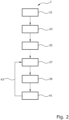
- Figure 2 shows the sequence of method 1 for determining the offset of the angular position sensor.
- the reference offset of a reference machine is determined using a method known from the prior art.
- a second step 33 the reference machine is set according to an in Figure 1
- the structure shown is accelerated to a reference speed and the reference current angle is measured in a third step 35.
- the values obtained in this way are subsequently used to determine the offset of the electrical machine or machine to be measured.
- the reference values are determined using the reference motor as an example.
- a machine to be measured is connected instead of the reference motor.
- the motor including the inverter can also be changed compared to the reference machine.
- the machine to be measured is accelerated to the reference speed and the current angle is measured in a fifth step 39.
- a sixth step 41 the set current angle is compared with the reference current angle.
- the deviation corresponds to the difference between the offset of the electrical machine to be measured and the reference offset Reference machine. Since this reference offset is known, the offset of the electrical machine to be measured can now be determined.
- a check of the specific offset is possible as a seventh step 43.
- the specific offset is set as the offset of the machine to be measured.
- the current angle present after acceleration to the reference speed is now essentially identical to the reference current angle, regardless of the different offsets of both machines.
- steps four to six and optionally seven for each motor produced to determine the offset of the angular position encoder.
- steps four to six and optionally seven can be carried out for every motor and inverter combination produced.
- Figure 3 shows an example of a current vector diagram in the complex plane.
- the d current Id 7 is plotted on the abscissa axis and the q current Iq 9 is plotted on the ordinate axis.
- the solid arrow 51 represents the vector of a reference current of the electrical reference machine.
- the reference current 51 is impressed at a predetermined reference speed.
- the applied reference current angle 53 is the argument of the vector 51. Since in this reference machine the angle of the angular position encoder is correct due to the known reference offset, the reference current ensures optimal operation of the reference machine.
- a further reference current vector 55 (shown in dotted lines) at a second reference speed, for example a negative speed.
- the resulting second argument 57 of this second reference current vector 55 can additionally be used as a second reference current angle 57 to determine the offset more precisely.
- a current 61 is impressed at the specified reference speed.
- the current angle 63 present is the argument of the current shown as a dashed vector 61. Since the angle of the angular position sensor in this machine to be measured is inaccurate due to the unknown offset, the current does not ensure optimal operation of the machine to be measured.
- a further current vector 65 (shown with long dashed lines) can be impressed at the second reference speed, for example a negative speed.
- the resulting second argument 67 of this second current vector 65 can additionally be used as a second current angle 67 to determine the offset more precisely.
- the difference between the reference current angle 53 of the reference machine and the current angle 63 of the machine to be measured at the same reference speed results in the deviation of the offset of the machine to be measured from the reference offset. Since the reference offset of the reference machine is known, the offset can be determined, for example, as the sum of the reference offset and the difference 59 of the current angle 63 and reference current angle 53 at the reference speed.
- a second offset 69 is thus created from the sum of the reference offset and the difference 69 of the second current 67 and second reference current angle 57 are determined at the second reference speed.
- the offset can optionally be corrected by the second offset.
- the uniform length of all vectors shows that the magnitudes of all currents are identical.
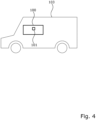
- FIG 4 is a schematic diagram of a vehicle 103, for example a hybrid vehicle or an electric vehicle, comprising an electric machine 100, in particular an electric motor for driving the vehicle, with an angular position sensor 101, the offset of which is determined using the method according to the invention.
- a vehicle 103 for example a hybrid vehicle or an electric vehicle, comprising an electric machine 100, in particular an electric motor for driving the vehicle, with an angular position sensor 101, the offset of which is determined using the method according to the invention.
Landscapes
- Physics & Mathematics (AREA)
- General Physics & Mathematics (AREA)
- Engineering & Computer Science (AREA)
- Power Engineering (AREA)
- Control Of Ac Motors In General (AREA)
- Control Of Motors That Do Not Use Commutators (AREA)
Applications Claiming Priority (1)
| Application Number | Priority Date | Filing Date | Title |
|---|---|---|---|
| DE102019111146.3A DE102019111146A1 (de) | 2019-04-30 | 2019-04-30 | Verfahren zum Bestimmen eines Offsets eines Winkellagegebers an einer Rotorwelle einer elektrischen Maschine |
Publications (2)
| Publication Number | Publication Date |
|---|---|
| EP3734232A1 EP3734232A1 (de) | 2020-11-04 |
| EP3734232B1 true EP3734232B1 (de) | 2023-09-20 |
Family
ID=70476111
Family Applications (1)
| Application Number | Title | Priority Date | Filing Date |
|---|---|---|---|
| EP20171982.0A Active EP3734232B1 (de) | 2019-04-30 | 2020-04-29 | Verfahren zum bestimmen eines offsets eines winkellagegebers an einer rotorwelle einer elektrischen maschine |
Country Status (6)
| Country | Link |
|---|---|
| US (1) | US11652430B2 (pl) |
| EP (1) | EP3734232B1 (pl) |
| CN (1) | CN111854585B (pl) |
| DE (1) | DE102019111146A1 (pl) |
| HU (1) | HUE064735T2 (pl) |
| PL (1) | PL3734232T3 (pl) |
Families Citing this family (2)
| Publication number | Priority date | Publication date | Assignee | Title |
|---|---|---|---|---|
| CN114812378B (zh) * | 2022-04-24 | 2023-09-05 | 深蓝汽车科技有限公司 | 电机角度传感器安装位置及故障测试系统及方法 |
| CN118264053B (zh) * | 2024-05-31 | 2024-07-26 | 常州亚同数控科技有限公司 | 一种基于编码器监测的高精度回转工件轴 |
Family Cites Families (13)
| Publication number | Priority date | Publication date | Assignee | Title |
|---|---|---|---|---|
| US5140245A (en) * | 1990-09-24 | 1992-08-18 | Westinghouse Electric Corp. | Pmg-based position sensor and synchronous drive incorporating same |
| US5489845A (en) * | 1994-09-19 | 1996-02-06 | Ford Motor Company | Encoder system and method for determining absolute rotor position by taking a mid value of the multiple coil output sinusoidal signals |
| US5742921A (en) * | 1996-05-06 | 1998-04-21 | Ford Motor Company | Automatic self-calibration method for position encoder |
| DE10302004B4 (de) * | 2003-01-21 | 2005-04-07 | BDT Büro- und Datentechnik GmbH & Co. KG | Schaltungsanordnung zur Ableitung drehrichtungsbezogener Ausgangssignale aus Encodereinrichtung mit zwei um einen Winkelbetrag versetzten Einzelencodern |
| WO2012066617A1 (ja) * | 2010-11-15 | 2012-05-24 | 三菱電機株式会社 | モータ制御装置 |
| DE102011087396A1 (de) * | 2010-12-21 | 2012-06-21 | Bayerische Motoren Werke Aktiengesellschaft | Vorrichtung und Verfahren zur Montage eines Winkellagegeberrotors an einer Rotorwelle eines Elektromotors |
| US8624564B2 (en) * | 2010-12-23 | 2014-01-07 | Caterpillar Inc. | Switched reluctance generator initial rotor position estimation |
| KR101382286B1 (ko) * | 2012-07-12 | 2014-04-08 | 기아자동차(주) | 차량 모터 위치센서의 옵셋 보정방법 |
| DE102013004954B4 (de) * | 2013-03-22 | 2022-07-07 | Audi Ag | Verfahren zum Betreiben einer mehrphasigen elektrischen Maschine sowie entsprechende mehrphasige elektrische Maschine |
| DE102013221767A1 (de) * | 2013-10-25 | 2015-04-30 | Robert Bosch Gmbh | Verfahren, Vorrichtung und System zum Betreiben einer rotierenden elektrischen Maschine |
| GB2527114B (en) * | 2014-06-12 | 2017-03-01 | Control Techniques Ltd | Method and system for determining an offset between a detector and a point on a motor |
| EP2985904B1 (en) * | 2014-08-11 | 2018-12-05 | Magneti Marelli S.p.A. | Method for the diagnosis of the offset of the resolver of an electric machine |
| DE102016203900A1 (de) * | 2016-03-10 | 2017-09-14 | Robert Bosch Gmbh | Verfahren zum Bestimmen eines Winkelfehlers zwischen einem mittels eines Winkelmesssystems ermittelten Drehwinkelwert und einem Referenzwert |
-
2019
- 2019-04-30 DE DE102019111146.3A patent/DE102019111146A1/de active Pending
-
2020
- 2020-04-29 US US16/861,535 patent/US11652430B2/en active Active
- 2020-04-29 EP EP20171982.0A patent/EP3734232B1/de active Active
- 2020-04-29 PL PL20171982.0T patent/PL3734232T3/pl unknown
- 2020-04-29 HU HUE20171982A patent/HUE064735T2/hu unknown
- 2020-04-30 CN CN202010367729.8A patent/CN111854585B/zh active Active
Also Published As
| Publication number | Publication date |
|---|---|
| EP3734232A1 (de) | 2020-11-04 |
| HUE064735T2 (hu) | 2024-04-28 |
| CN111854585B (zh) | 2025-01-07 |
| US20200350840A1 (en) | 2020-11-05 |
| US11652430B2 (en) | 2023-05-16 |
| CN111854585A (zh) | 2020-10-30 |
| DE102019111146A1 (de) | 2020-11-05 |
| PL3734232T3 (pl) | 2024-05-13 |
Similar Documents
| Publication | Publication Date | Title |
|---|---|---|
| EP2601739B1 (de) | Verfahren und schaltungsanordnung zur überprüfung der rotorposition einer synchronmaschine | |
| EP2817592B1 (de) | Kalibrierung und überwachung eines winkelmesssystems für elektrische maschinen | |
| EP3296701A1 (de) | Sensorvorrichtung zur bestimmung der position des rotors einer elektrischen maschine und steuervorrichtung fuer einen elektromotor | |
| EP0746090A2 (de) | Verfahren zur Läuferpositionsbestimmung für einen Rotations- oder Linearmotor | |
| EP3734232B1 (de) | Verfahren zum bestimmen eines offsets eines winkellagegebers an einer rotorwelle einer elektrischen maschine | |
| EP2671319A2 (de) | Verfahren, vorrichtung und computerprogramm zum ermitteln eines offsetwinkels in einer elektromaschine | |
| DE102013204382A1 (de) | Steuereinrichtung und Verfahren zum Ansteuern einer Drehfeldmaschine | |
| EP3014756B1 (de) | Verfahren zur erkennung einer winkelfehlstellung eines elektrischen motors | |
| EP2596579B1 (de) | Verfahren und vorrichtung zur sensorlosen lageerkennung einer elektronisch kommutierten elektrischen maschine | |
| EP3556011B1 (de) | Verfahren zur bestimmung der winkellage des rotors eines von einem wechselrichter gespeisten synchronmotors und eine vorrichtung zur durchführung des verfahrens | |
| DE102016214497A1 (de) | Steuerungseinheit und Verfahren zum Steuern einer elektrischen Maschine | |
| DE102013221709A1 (de) | Verfahren und Vorrichtung zum Ermitteln einer Abweichung eines Drehzahlsensors einer Synchronmaschine | |
| DE102019130180A1 (de) | Verfahren zum Bestimmen eines Offsets eines Winkellagegebers an einer Rotorwelle einer elektrischen Synchronmaschine mit einem Strom- oder Spannungstimingoffsets eines Inverters | |
| EP3704790B1 (de) | Verfahren zur ermittlung der rotorposition von synchron laufenden elektrischen maschinen ohne mechanischen geber | |
| EP4327452B1 (de) | Temperaturbestimmungsverfahren für magnettemperaturen an magneten elektrischer motoren | |
| DE102010000991A1 (de) | Verfahren zur Phasenabrisserkennung an einer an einem Stromrichter betriebenen Drehfeldmaschine | |
| EP1746718B1 (de) | Verfahren zur direkten Regelung der Reaktanz einer Drehstrommaschine | |
| DE102021116963B4 (de) | Verfahren zur Drehmomentschätzung einer elektrischen Maschine, Steuereinheit zur Ausführung dieses Verfahrens und elektrischer Traktionsantrieb mit derartiger Steuereinheit | |
| DE102019125926A1 (de) | Verfahren zum Betrieb einer elektrischen Maschine, elektrische Maschine, Kraftfahrzeug, Verfahren zum Betrieb eines Kraftfahrzeugs | |
| EP4224704B1 (de) | Elektronisch kommutierte elektrische maschine mit mehreren teilmaschinen sowie verfahren zum betreiben einer solchen elektrischen maschine | |
| EP1507330A2 (de) | Einrichtung und Verfahren zur Rotorpositionsbestimmung einer elektrischen Maschine | |
| DE102024115754A1 (de) | System zum Betreiben einer Elektromaschine | |
| EP4645676A1 (de) | Verfahren zum betreiben eines bürstenlosen gleichstrommotors, anordnung zur ausführung des verfahrens sowie fahrzeug | |
| EP3297153B1 (de) | Verfahren und vorrichtung zum bestimmen einer läuferlage eines läufers einer elektronisch kommutierten elektrischen maschine | |
| DE102023110472A1 (de) | Verfahren und Vorrichtung zum Abgleich einer Drehmoment-Steuerung einer elektrischen Maschine |
Legal Events
| Date | Code | Title | Description |
|---|---|---|---|
| PUAI | Public reference made under article 153(3) epc to a published international application that has entered the european phase |
Free format text: ORIGINAL CODE: 0009012 |
|
| STAA | Information on the status of an ep patent application or granted ep patent |
Free format text: STATUS: THE APPLICATION HAS BEEN PUBLISHED |
|
| AK | Designated contracting states |
Kind code of ref document: A1 Designated state(s): AL AT BE BG CH CY CZ DE DK EE ES FI FR GB GR HR HU IE IS IT LI LT LU LV MC MK MT NL NO PL PT RO RS SE SI SK SM TR |
|
| AX | Request for extension of the european patent |
Extension state: BA ME |
|
| STAA | Information on the status of an ep patent application or granted ep patent |
Free format text: STATUS: REQUEST FOR EXAMINATION WAS MADE |
|
| 17P | Request for examination filed |
Effective date: 20210504 |
|
| RBV | Designated contracting states (corrected) |
Designated state(s): AL AT BE BG CH CY CZ DE DK EE ES FI FR GB GR HR HU IE IS IT LI LT LU LV MC MK MT NL NO PL PT RO RS SE SI SK SM TR |
|
| STAA | Information on the status of an ep patent application or granted ep patent |
Free format text: STATUS: EXAMINATION IS IN PROGRESS |
|
| 17Q | First examination report despatched |
Effective date: 20220118 |
|
| RAP3 | Party data changed (applicant data changed or rights of an application transferred) |
Owner name: VALEO EAUTOMOTIVE GERMANY GMBH |
|
| GRAP | Despatch of communication of intention to grant a patent |
Free format text: ORIGINAL CODE: EPIDOSNIGR1 |
|
| STAA | Information on the status of an ep patent application or granted ep patent |
Free format text: STATUS: GRANT OF PATENT IS INTENDED |
|
| INTG | Intention to grant announced |
Effective date: 20230130 |
|
| GRAS | Grant fee paid |
Free format text: ORIGINAL CODE: EPIDOSNIGR3 |
|
| P01 | Opt-out of the competence of the unified patent court (upc) registered |
Effective date: 20230528 |
|
| GRAA | (expected) grant |
Free format text: ORIGINAL CODE: 0009210 |
|
| STAA | Information on the status of an ep patent application or granted ep patent |
Free format text: STATUS: THE PATENT HAS BEEN GRANTED |
|
| AK | Designated contracting states |
Kind code of ref document: B1 Designated state(s): AL AT BE BG CH CY CZ DE DK EE ES FI FR GB GR HR HU IE IS IT LI LT LU LV MC MK MT NL NO PL PT RO RS SE SI SK SM TR |
|
| REG | Reference to a national code |
Ref country code: GB Ref legal event code: FG4D Free format text: NOT ENGLISH |
|
| REG | Reference to a national code |
Ref country code: CH Ref legal event code: EP |
|
| REG | Reference to a national code |
Ref country code: IE Ref legal event code: FG4D Free format text: LANGUAGE OF EP DOCUMENT: GERMAN |
|
| REG | Reference to a national code |
Ref country code: DE Ref legal event code: R096 Ref document number: 502020005288 Country of ref document: DE |
|
| REG | Reference to a national code |
Ref country code: LT Ref legal event code: MG9D |
|
| PG25 | Lapsed in a contracting state [announced via postgrant information from national office to epo] |
Ref country code: GR Free format text: LAPSE BECAUSE OF FAILURE TO SUBMIT A TRANSLATION OF THE DESCRIPTION OR TO PAY THE FEE WITHIN THE PRESCRIBED TIME-LIMIT Effective date: 20231221 |
|
| REG | Reference to a national code |
Ref country code: NL Ref legal event code: MP Effective date: 20230920 |
|
| PG25 | Lapsed in a contracting state [announced via postgrant information from national office to epo] |
Ref country code: SE Free format text: LAPSE BECAUSE OF FAILURE TO SUBMIT A TRANSLATION OF THE DESCRIPTION OR TO PAY THE FEE WITHIN THE PRESCRIBED TIME-LIMIT Effective date: 20230920 Ref country code: RS Free format text: LAPSE BECAUSE OF FAILURE TO SUBMIT A TRANSLATION OF THE DESCRIPTION OR TO PAY THE FEE WITHIN THE PRESCRIBED TIME-LIMIT Effective date: 20230920 Ref country code: NO Free format text: LAPSE BECAUSE OF FAILURE TO SUBMIT A TRANSLATION OF THE DESCRIPTION OR TO PAY THE FEE WITHIN THE PRESCRIBED TIME-LIMIT Effective date: 20231220 Ref country code: LV Free format text: LAPSE BECAUSE OF FAILURE TO SUBMIT A TRANSLATION OF THE DESCRIPTION OR TO PAY THE FEE WITHIN THE PRESCRIBED TIME-LIMIT Effective date: 20230920 Ref country code: LT Free format text: LAPSE BECAUSE OF FAILURE TO SUBMIT A TRANSLATION OF THE DESCRIPTION OR TO PAY THE FEE WITHIN THE PRESCRIBED TIME-LIMIT Effective date: 20230920 Ref country code: HR Free format text: LAPSE BECAUSE OF FAILURE TO SUBMIT A TRANSLATION OF THE DESCRIPTION OR TO PAY THE FEE WITHIN THE PRESCRIBED TIME-LIMIT Effective date: 20230920 Ref country code: GR Free format text: LAPSE BECAUSE OF FAILURE TO SUBMIT A TRANSLATION OF THE DESCRIPTION OR TO PAY THE FEE WITHIN THE PRESCRIBED TIME-LIMIT Effective date: 20231221 Ref country code: FI Free format text: LAPSE BECAUSE OF FAILURE TO SUBMIT A TRANSLATION OF THE DESCRIPTION OR TO PAY THE FEE WITHIN THE PRESCRIBED TIME-LIMIT Effective date: 20230920 |
|
| PG25 | Lapsed in a contracting state [announced via postgrant information from national office to epo] |
Ref country code: NL Free format text: LAPSE BECAUSE OF FAILURE TO SUBMIT A TRANSLATION OF THE DESCRIPTION OR TO PAY THE FEE WITHIN THE PRESCRIBED TIME-LIMIT Effective date: 20230920 |
|
| PG25 | Lapsed in a contracting state [announced via postgrant information from national office to epo] |
Ref country code: IS Free format text: LAPSE BECAUSE OF FAILURE TO SUBMIT A TRANSLATION OF THE DESCRIPTION OR TO PAY THE FEE WITHIN THE PRESCRIBED TIME-LIMIT Effective date: 20240120 |
|
| PG25 | Lapsed in a contracting state [announced via postgrant information from national office to epo] |
Ref country code: ES Free format text: LAPSE BECAUSE OF FAILURE TO SUBMIT A TRANSLATION OF THE DESCRIPTION OR TO PAY THE FEE WITHIN THE PRESCRIBED TIME-LIMIT Effective date: 20230920 |
|
| REG | Reference to a national code |
Ref country code: HU Ref legal event code: AG4A Ref document number: E064735 Country of ref document: HU |
|
| PG25 | Lapsed in a contracting state [announced via postgrant information from national office to epo] |
Ref country code: SM Free format text: LAPSE BECAUSE OF FAILURE TO SUBMIT A TRANSLATION OF THE DESCRIPTION OR TO PAY THE FEE WITHIN THE PRESCRIBED TIME-LIMIT Effective date: 20230920 Ref country code: RO Free format text: LAPSE BECAUSE OF FAILURE TO SUBMIT A TRANSLATION OF THE DESCRIPTION OR TO PAY THE FEE WITHIN THE PRESCRIBED TIME-LIMIT Effective date: 20230920 Ref country code: IS Free format text: LAPSE BECAUSE OF FAILURE TO SUBMIT A TRANSLATION OF THE DESCRIPTION OR TO PAY THE FEE WITHIN THE PRESCRIBED TIME-LIMIT Effective date: 20240120 Ref country code: ES Free format text: LAPSE BECAUSE OF FAILURE TO SUBMIT A TRANSLATION OF THE DESCRIPTION OR TO PAY THE FEE WITHIN THE PRESCRIBED TIME-LIMIT Effective date: 20230920 Ref country code: EE Free format text: LAPSE BECAUSE OF FAILURE TO SUBMIT A TRANSLATION OF THE DESCRIPTION OR TO PAY THE FEE WITHIN THE PRESCRIBED TIME-LIMIT Effective date: 20230920 Ref country code: CZ Free format text: LAPSE BECAUSE OF FAILURE TO SUBMIT A TRANSLATION OF THE DESCRIPTION OR TO PAY THE FEE WITHIN THE PRESCRIBED TIME-LIMIT Effective date: 20230920 Ref country code: SK Free format text: LAPSE BECAUSE OF FAILURE TO SUBMIT A TRANSLATION OF THE DESCRIPTION OR TO PAY THE FEE WITHIN THE PRESCRIBED TIME-LIMIT Effective date: 20230920 Ref country code: PT Free format text: LAPSE BECAUSE OF FAILURE TO SUBMIT A TRANSLATION OF THE DESCRIPTION OR TO PAY THE FEE WITHIN THE PRESCRIBED TIME-LIMIT Effective date: 20240122 |
|
| PG25 | Lapsed in a contracting state [announced via postgrant information from national office to epo] |
Ref country code: IT Free format text: LAPSE BECAUSE OF FAILURE TO SUBMIT A TRANSLATION OF THE DESCRIPTION OR TO PAY THE FEE WITHIN THE PRESCRIBED TIME-LIMIT Effective date: 20230920 |
|
| REG | Reference to a national code |
Ref country code: DE Ref legal event code: R097 Ref document number: 502020005288 Country of ref document: DE |
|
| PG25 | Lapsed in a contracting state [announced via postgrant information from national office to epo] |
Ref country code: DK Free format text: LAPSE BECAUSE OF FAILURE TO SUBMIT A TRANSLATION OF THE DESCRIPTION OR TO PAY THE FEE WITHIN THE PRESCRIBED TIME-LIMIT Effective date: 20230920 |
|
| PLBE | No opposition filed within time limit |
Free format text: ORIGINAL CODE: 0009261 |
|
| STAA | Information on the status of an ep patent application or granted ep patent |
Free format text: STATUS: NO OPPOSITION FILED WITHIN TIME LIMIT |
|
| PG25 | Lapsed in a contracting state [announced via postgrant information from national office to epo] |
Ref country code: DK Free format text: LAPSE BECAUSE OF FAILURE TO SUBMIT A TRANSLATION OF THE DESCRIPTION OR TO PAY THE FEE WITHIN THE PRESCRIBED TIME-LIMIT Effective date: 20230920 |
|
| 26N | No opposition filed |
Effective date: 20240621 |
|
| PG25 | Lapsed in a contracting state [announced via postgrant information from national office to epo] |
Ref country code: SI Free format text: LAPSE BECAUSE OF FAILURE TO SUBMIT A TRANSLATION OF THE DESCRIPTION OR TO PAY THE FEE WITHIN THE PRESCRIBED TIME-LIMIT Effective date: 20230920 |
|
| PG25 | Lapsed in a contracting state [announced via postgrant information from national office to epo] |
Ref country code: SI Free format text: LAPSE BECAUSE OF FAILURE TO SUBMIT A TRANSLATION OF THE DESCRIPTION OR TO PAY THE FEE WITHIN THE PRESCRIBED TIME-LIMIT Effective date: 20230920 |
|
| PG25 | Lapsed in a contracting state [announced via postgrant information from national office to epo] |
Ref country code: BG Free format text: LAPSE BECAUSE OF FAILURE TO SUBMIT A TRANSLATION OF THE DESCRIPTION OR TO PAY THE FEE WITHIN THE PRESCRIBED TIME-LIMIT Effective date: 20230920 |
|
| PG25 | Lapsed in a contracting state [announced via postgrant information from national office to epo] |
Ref country code: MC Free format text: LAPSE BECAUSE OF FAILURE TO SUBMIT A TRANSLATION OF THE DESCRIPTION OR TO PAY THE FEE WITHIN THE PRESCRIBED TIME-LIMIT Effective date: 20230920 |
|
| PG25 | Lapsed in a contracting state [announced via postgrant information from national office to epo] |
Ref country code: MC Free format text: LAPSE BECAUSE OF FAILURE TO SUBMIT A TRANSLATION OF THE DESCRIPTION OR TO PAY THE FEE WITHIN THE PRESCRIBED TIME-LIMIT Effective date: 20230920 Ref country code: BG Free format text: LAPSE BECAUSE OF FAILURE TO SUBMIT A TRANSLATION OF THE DESCRIPTION OR TO PAY THE FEE WITHIN THE PRESCRIBED TIME-LIMIT Effective date: 20230920 |
|
| REG | Reference to a national code |
Ref country code: CH Ref legal event code: PL |
|
| PG25 | Lapsed in a contracting state [announced via postgrant information from national office to epo] |
Ref country code: LU Free format text: LAPSE BECAUSE OF NON-PAYMENT OF DUE FEES Effective date: 20240429 |
|
| GBPC | Gb: european patent ceased through non-payment of renewal fee |
Effective date: 20240429 |
|
| REG | Reference to a national code |
Ref country code: BE Ref legal event code: MM Effective date: 20240430 |
|
| PG25 | Lapsed in a contracting state [announced via postgrant information from national office to epo] |
Ref country code: LU Free format text: LAPSE BECAUSE OF NON-PAYMENT OF DUE FEES Effective date: 20240429 |
|
| PG25 | Lapsed in a contracting state [announced via postgrant information from national office to epo] |
Ref country code: BE Free format text: LAPSE BECAUSE OF NON-PAYMENT OF DUE FEES Effective date: 20240430 |
|
| PG25 | Lapsed in a contracting state [announced via postgrant information from national office to epo] |
Ref country code: GB Free format text: LAPSE BECAUSE OF NON-PAYMENT OF DUE FEES Effective date: 20240429 |
|
| PG25 | Lapsed in a contracting state [announced via postgrant information from national office to epo] |
Ref country code: GB Free format text: LAPSE BECAUSE OF NON-PAYMENT OF DUE FEES Effective date: 20240429 Ref country code: BE Free format text: LAPSE BECAUSE OF NON-PAYMENT OF DUE FEES Effective date: 20240430 Ref country code: CH Free format text: LAPSE BECAUSE OF NON-PAYMENT OF DUE FEES Effective date: 20240430 |
|
| PG25 | Lapsed in a contracting state [announced via postgrant information from national office to epo] |
Ref country code: IE Free format text: LAPSE BECAUSE OF NON-PAYMENT OF DUE FEES Effective date: 20240429 |
|
| PGFP | Annual fee paid to national office [announced via postgrant information from national office to epo] |
Ref country code: PL Payment date: 20250320 Year of fee payment: 6 |
|
| PGFP | Annual fee paid to national office [announced via postgrant information from national office to epo] |
Ref country code: DE Payment date: 20250411 Year of fee payment: 6 |
|
| PGFP | Annual fee paid to national office [announced via postgrant information from national office to epo] |
Ref country code: HU Payment date: 20250320 Year of fee payment: 6 |
|
| PGFP | Annual fee paid to national office [announced via postgrant information from national office to epo] |
Ref country code: FR Payment date: 20250429 Year of fee payment: 6 |
|
| PGFP | Annual fee paid to national office [announced via postgrant information from national office to epo] |
Ref country code: AT Payment date: 20250721 Year of fee payment: 5 |
|
| PG25 | Lapsed in a contracting state [announced via postgrant information from national office to epo] |
Ref country code: CY Free format text: LAPSE BECAUSE OF FAILURE TO SUBMIT A TRANSLATION OF THE DESCRIPTION OR TO PAY THE FEE WITHIN THE PRESCRIBED TIME-LIMIT; INVALID AB INITIO Effective date: 20200429 |