EP3734232B1 - Method for determining an offset of an angular position sensor on a rotor shaft of an electric machine - Google Patents
Method for determining an offset of an angular position sensor on a rotor shaft of an electric machine Download PDFInfo
- Publication number
- EP3734232B1 EP3734232B1 EP20171982.0A EP20171982A EP3734232B1 EP 3734232 B1 EP3734232 B1 EP 3734232B1 EP 20171982 A EP20171982 A EP 20171982A EP 3734232 B1 EP3734232 B1 EP 3734232B1
- Authority
- EP
- European Patent Office
- Prior art keywords
- current
- offset
- angular position
- angle
- current angle
- Prior art date
- Legal status (The legal status is an assumption and is not a legal conclusion. Google has not performed a legal analysis and makes no representation as to the accuracy of the status listed.)
- Active
Links
- 238000000034 method Methods 0.000 title claims description 21
- 238000004519 manufacturing process Methods 0.000 claims description 9
- 239000013598 vector Substances 0.000 description 10
- 238000010586 diagram Methods 0.000 description 3
- 238000004804 winding Methods 0.000 description 3
- 230000003044 adaptive effect Effects 0.000 description 2
- 230000001360 synchronised effect Effects 0.000 description 2
- 230000001133 acceleration Effects 0.000 description 1
- 238000004458 analytical method Methods 0.000 description 1
- 238000004364 calculation method Methods 0.000 description 1
- 238000010276 construction Methods 0.000 description 1
- 230000001419 dependent effect Effects 0.000 description 1
- 238000005265 energy consumption Methods 0.000 description 1
- 230000005284 excitation Effects 0.000 description 1
- 238000010438 heat treatment Methods 0.000 description 1
- 238000009434 installation Methods 0.000 description 1
- 238000005259 measurement Methods 0.000 description 1
- 239000007787 solid Substances 0.000 description 1
Images


Classifications
-
- H—ELECTRICITY
- H02—GENERATION; CONVERSION OR DISTRIBUTION OF ELECTRIC POWER
- H02P—CONTROL OR REGULATION OF ELECTRIC MOTORS, ELECTRIC GENERATORS OR DYNAMO-ELECTRIC CONVERTERS; CONTROLLING TRANSFORMERS, REACTORS OR CHOKE COILS
- H02P6/00—Arrangements for controlling synchronous motors or other dynamo-electric motors using electronic commutation dependent on the rotor position; Electronic commutators therefor
- H02P6/14—Electronic commutators
- H02P6/16—Circuit arrangements for detecting position
- H02P6/17—Circuit arrangements for detecting position and for generating speed information
-
- G—PHYSICS
- G01—MEASURING; TESTING
- G01D—MEASURING NOT SPECIALLY ADAPTED FOR A SPECIFIC VARIABLE; ARRANGEMENTS FOR MEASURING TWO OR MORE VARIABLES NOT COVERED IN A SINGLE OTHER SUBCLASS; TARIFF METERING APPARATUS; MEASURING OR TESTING NOT OTHERWISE PROVIDED FOR
- G01D18/00—Testing or calibrating apparatus or arrangements provided for in groups G01D1/00 - G01D15/00
-
- G—PHYSICS
- G01—MEASURING; TESTING
- G01B—MEASURING LENGTH, THICKNESS OR SIMILAR LINEAR DIMENSIONS; MEASURING ANGLES; MEASURING AREAS; MEASURING IRREGULARITIES OF SURFACES OR CONTOURS
- G01B7/00—Measuring arrangements characterised by the use of electric or magnetic techniques
- G01B7/003—Measuring arrangements characterised by the use of electric or magnetic techniques for measuring position, not involving coordinate determination
-
- G—PHYSICS
- G01—MEASURING; TESTING
- G01D—MEASURING NOT SPECIALLY ADAPTED FOR A SPECIFIC VARIABLE; ARRANGEMENTS FOR MEASURING TWO OR MORE VARIABLES NOT COVERED IN A SINGLE OTHER SUBCLASS; TARIFF METERING APPARATUS; MEASURING OR TESTING NOT OTHERWISE PROVIDED FOR
- G01D18/00—Testing or calibrating apparatus or arrangements provided for in groups G01D1/00 - G01D15/00
- G01D18/001—Calibrating encoders
-
- G—PHYSICS
- G01—MEASURING; TESTING
- G01D—MEASURING NOT SPECIALLY ADAPTED FOR A SPECIFIC VARIABLE; ARRANGEMENTS FOR MEASURING TWO OR MORE VARIABLES NOT COVERED IN A SINGLE OTHER SUBCLASS; TARIFF METERING APPARATUS; MEASURING OR TESTING NOT OTHERWISE PROVIDED FOR
- G01D5/00—Mechanical means for transferring the output of a sensing member; Means for converting the output of a sensing member to another variable where the form or nature of the sensing member does not constrain the means for converting; Transducers not specially adapted for a specific variable
- G01D5/12—Mechanical means for transferring the output of a sensing member; Means for converting the output of a sensing member to another variable where the form or nature of the sensing member does not constrain the means for converting; Transducers not specially adapted for a specific variable using electric or magnetic means
- G01D5/244—Mechanical means for transferring the output of a sensing member; Means for converting the output of a sensing member to another variable where the form or nature of the sensing member does not constrain the means for converting; Transducers not specially adapted for a specific variable using electric or magnetic means influencing characteristics of pulses or pulse trains; generating pulses or pulse trains
- G01D5/245—Mechanical means for transferring the output of a sensing member; Means for converting the output of a sensing member to another variable where the form or nature of the sensing member does not constrain the means for converting; Transducers not specially adapted for a specific variable using electric or magnetic means influencing characteristics of pulses or pulse trains; generating pulses or pulse trains using a variable number of pulses in a train
- G01D5/2454—Encoders incorporating incremental and absolute signals
- G01D5/2455—Encoders incorporating incremental and absolute signals with incremental and absolute tracks on the same encoder
- G01D5/2457—Incremental encoders having reference marks
-
- G—PHYSICS
- G01—MEASURING; TESTING
- G01D—MEASURING NOT SPECIALLY ADAPTED FOR A SPECIFIC VARIABLE; ARRANGEMENTS FOR MEASURING TWO OR MORE VARIABLES NOT COVERED IN A SINGLE OTHER SUBCLASS; TARIFF METERING APPARATUS; MEASURING OR TESTING NOT OTHERWISE PROVIDED FOR
- G01D5/00—Mechanical means for transferring the output of a sensing member; Means for converting the output of a sensing member to another variable where the form or nature of the sensing member does not constrain the means for converting; Transducers not specially adapted for a specific variable
- G01D5/12—Mechanical means for transferring the output of a sensing member; Means for converting the output of a sensing member to another variable where the form or nature of the sensing member does not constrain the means for converting; Transducers not specially adapted for a specific variable using electric or magnetic means
- G01D5/244—Mechanical means for transferring the output of a sensing member; Means for converting the output of a sensing member to another variable where the form or nature of the sensing member does not constrain the means for converting; Transducers not specially adapted for a specific variable using electric or magnetic means influencing characteristics of pulses or pulse trains; generating pulses or pulse trains
- G01D5/249—Mechanical means for transferring the output of a sensing member; Means for converting the output of a sensing member to another variable where the form or nature of the sensing member does not constrain the means for converting; Transducers not specially adapted for a specific variable using electric or magnetic means influencing characteristics of pulses or pulse trains; generating pulses or pulse trains using pulse code
- G01D5/2497—Absolute encoders
-
- G—PHYSICS
- G01—MEASURING; TESTING
- G01D—MEASURING NOT SPECIALLY ADAPTED FOR A SPECIFIC VARIABLE; ARRANGEMENTS FOR MEASURING TWO OR MORE VARIABLES NOT COVERED IN A SINGLE OTHER SUBCLASS; TARIFF METERING APPARATUS; MEASURING OR TESTING NOT OTHERWISE PROVIDED FOR
- G01D5/00—Mechanical means for transferring the output of a sensing member; Means for converting the output of a sensing member to another variable where the form or nature of the sensing member does not constrain the means for converting; Transducers not specially adapted for a specific variable
- G01D5/12—Mechanical means for transferring the output of a sensing member; Means for converting the output of a sensing member to another variable where the form or nature of the sensing member does not constrain the means for converting; Transducers not specially adapted for a specific variable using electric or magnetic means
- G01D5/244—Mechanical means for transferring the output of a sensing member; Means for converting the output of a sensing member to another variable where the form or nature of the sensing member does not constrain the means for converting; Transducers not specially adapted for a specific variable using electric or magnetic means influencing characteristics of pulses or pulse trains; generating pulses or pulse trains
- G01D5/24471—Error correction
- G01D5/2448—Correction of gain, threshold, offset or phase control
Definitions
- the invention relates to a method for determining an offset of an angular position sensor on a rotor shaft of an electrical machine.
- Electric motors as electrical machines are well known and are increasingly being used to drive vehicles.
- An electric motor consists of a stator and a rotor.
- the stator includes a large number of slots in which the windings are routed.
- the rotor is located in the stator and is connected to a rotor shaft.
- To control the electrical machine it is necessary to know the exact angular position of the rotor in the stator.
- the position angle can be continuously measured using a so-called angular position sensor.
- the angular position sensor can be attached to the stator or a bearing plate, for example, but must be at a distance from the rotor.
- the object of the present invention is to provide a method for determining the offset of the angular position sensor that is simple and time-saving.
- the method for determining an offset of an angular position sensor comprises a reference offset of a reference angular position sensor of an electric reference machine at a reference speed and a reference current with a reference current angle and a reference amount is known, the following steps, imprinting a current with the reference amount, setting a current angle of the current to reach the reference speed, comparing the current angle with the reference current angle and the reference offset, determining the offset from this comparison.
- the reference current with reference current angle and reference amount is determined in an electrical reference machine at a reference speed.
- the production-related reference offset of the angular position sensor was determined in advance on an engine test bench using a known method.
- the control now sets a reference current with an optimal reference current angle.
- the current components q-current and d-current include the current angle in the complex plane, with the length of a current vector representing the reference amount of the reference current.
- the manufacturing-related deviation when installing the angular position encoder and the resulting offset of the angular position encoder are individual to the engine and therefore different compared to the reference machine.
- the offset must therefore be determined individually for each electrical machine.
- the optimal reference current angle with the reference amount at the reference speed and the reference offset are known and in a similar electrical machine the same, optimal current angle with the reference amount and the offset at the reference speed would have to be set, the difference between the reference current angle and the current angle is essentially due to the Production-related deviation caused by the offset of the angular position encoder. Essentially this means that, for example, different electrical resistances in the windings of the various electrical machines have a negligible influence on the current angle.
- the current angle of the electrical machine to be tested would be identical to the reference current angle of the electrical reference machine if both angle position sensors had the same offset.
- the deviation between the Reference current angle and the current angle corresponds to the deviation of the offset of the electrical machine to be measured from the reference offset of the reference machine. Since the reference offset is known, the offset of the electrical machine to be measured can be determined.
- the offset can preferably be determined at two different reference speeds and an average value can be formed from this.
- a further improvement in the determination of the offset can be achieved by forming mean values or weighted average values from the values at the reference speeds.
- the reference speeds can have the same magnitude but lie in different directions of rotation.
- the reference speed can be in the range between one third and two thirds of a rated engine speed.
- the current flowing is sufficiently large and the losses due to bearings and heating are still small enough to be able to measure an optimal current angle.
- the method can be carried out as an end-of-line test of series production.
- the specific offset of the angular position sensor of the electrical machine is essentially independent of the connected inverter, since the production-related offset of the angular position sensor is always greater than an offset of the inverter caused by the signal transit time.
- FIG 1 an electrical machine 21, in particular an electric motor, is shown schematically.
- the electrical machine 21 is connected via three phases 27 to an inverter 19, which supplies the electrical machine 21 with alternating current from a - for example battery - direct current source (not shown).
- a pulse width modulator 17 switches the switching elements in the inverter 19 in order to supply the electrical machine with an alternating voltage from a direct voltage source.
- the pulse width modulator 17 is specified by a current controller 15 as to which duty cycle the inverter 19 should set when inverting the current.
- the current controller 15 receives feedback 23 from the inverter 19 about the current of the three phases 27 that is actually fed into the electrical machine.
- the current controller 15 receives the specifications for the current to be impressed with the current amount and current angle, i.e. values for q-9 and d-current 7, from a current predeterminer 13 in the speed controller 29.
- the current predeterminer 13 receives the necessary current angle 5 from the adaptive speed control 11 that the electric machine 21 is supposed to reach. From the electric machine 21, the adaptive speed control 11 in turn receives feedback 25 about the actual speed at the electric machine 21 and can, if necessary, correct the speed by means of an intervention by the current predeterminer.
- the speed controller 29 and its components are only necessary for determining the offset, it can be dispensed with when operating the electric machine after determining the offset, for example in a vehicle.
- the offset can be determined at a known reference offset of the reference machine on electrical series machines of identical construction.
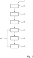
- Figure 2 shows the sequence of method 1 for determining the offset of the angular position sensor.
- the reference offset of a reference machine is determined using a method known from the prior art.
- a second step 33 the reference machine is set according to an in Figure 1
- the structure shown is accelerated to a reference speed and the reference current angle is measured in a third step 35.
- the values obtained in this way are subsequently used to determine the offset of the electrical machine or machine to be measured.
- the reference values are determined using the reference motor as an example.
- a machine to be measured is connected instead of the reference motor.
- the motor including the inverter can also be changed compared to the reference machine.
- the machine to be measured is accelerated to the reference speed and the current angle is measured in a fifth step 39.
- a sixth step 41 the set current angle is compared with the reference current angle.
- the deviation corresponds to the difference between the offset of the electrical machine to be measured and the reference offset Reference machine. Since this reference offset is known, the offset of the electrical machine to be measured can now be determined.
- a check of the specific offset is possible as a seventh step 43.
- the specific offset is set as the offset of the machine to be measured.
- the current angle present after acceleration to the reference speed is now essentially identical to the reference current angle, regardless of the different offsets of both machines.
- steps four to six and optionally seven for each motor produced to determine the offset of the angular position encoder.
- steps four to six and optionally seven can be carried out for every motor and inverter combination produced.
- Figure 3 shows an example of a current vector diagram in the complex plane.
- the d current Id 7 is plotted on the abscissa axis and the q current Iq 9 is plotted on the ordinate axis.
- the solid arrow 51 represents the vector of a reference current of the electrical reference machine.
- the reference current 51 is impressed at a predetermined reference speed.
- the applied reference current angle 53 is the argument of the vector 51. Since in this reference machine the angle of the angular position encoder is correct due to the known reference offset, the reference current ensures optimal operation of the reference machine.
- a further reference current vector 55 (shown in dotted lines) at a second reference speed, for example a negative speed.
- the resulting second argument 57 of this second reference current vector 55 can additionally be used as a second reference current angle 57 to determine the offset more precisely.
- a current 61 is impressed at the specified reference speed.
- the current angle 63 present is the argument of the current shown as a dashed vector 61. Since the angle of the angular position sensor in this machine to be measured is inaccurate due to the unknown offset, the current does not ensure optimal operation of the machine to be measured.
- a further current vector 65 (shown with long dashed lines) can be impressed at the second reference speed, for example a negative speed.
- the resulting second argument 67 of this second current vector 65 can additionally be used as a second current angle 67 to determine the offset more precisely.
- the difference between the reference current angle 53 of the reference machine and the current angle 63 of the machine to be measured at the same reference speed results in the deviation of the offset of the machine to be measured from the reference offset. Since the reference offset of the reference machine is known, the offset can be determined, for example, as the sum of the reference offset and the difference 59 of the current angle 63 and reference current angle 53 at the reference speed.
- a second offset 69 is thus created from the sum of the reference offset and the difference 69 of the second current 67 and second reference current angle 57 are determined at the second reference speed.
- the offset can optionally be corrected by the second offset.
- the uniform length of all vectors shows that the magnitudes of all currents are identical.
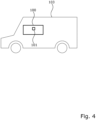
- FIG 4 is a schematic diagram of a vehicle 103, for example a hybrid vehicle or an electric vehicle, comprising an electric machine 100, in particular an electric motor for driving the vehicle, with an angular position sensor 101, the offset of which is determined using the method according to the invention.
- a vehicle 103 for example a hybrid vehicle or an electric vehicle, comprising an electric machine 100, in particular an electric motor for driving the vehicle, with an angular position sensor 101, the offset of which is determined using the method according to the invention.
Landscapes
- Physics & Mathematics (AREA)
- General Physics & Mathematics (AREA)
- Engineering & Computer Science (AREA)
- Power Engineering (AREA)
- Control Of Ac Motors In General (AREA)
Description
Die Erfindung betrifft ein Verfahren zum Bestimmen eines Offsets eines Winkellagegebers an einer Rotorwelle einer elektrischen Maschine.The invention relates to a method for determining an offset of an angular position sensor on a rotor shaft of an electrical machine.
Elektromotoren als elektrische Maschinen sind allgemein bekannt und finden zunehmend Anwendung für den Antrieb von Fahrzeugen. Ein Elektromotor besteht aus einem Stator und einem Rotor.Electric motors as electrical machines are well known and are increasingly being used to drive vehicles. An electric motor consists of a stator and a rotor.
Der Stator umfasst eine Vielzahl von Slots, in denen die Windungen geführt werden. Der Rotor befindet sich im Stator und ist mit einer Rotorwelle verbunden. Für die Steuerung der elektrischen Maschine ist es nötig die genaue Winkellage des Rotors im Stator zu kennen. Mittels eines sogenannten Winkellagegebers kann der Lagewinkel fortlaufend gemessen werden. Der Winkellagegeber kann beispielsweise am Stator oder einem Lagerschild befestigt werden, muss jedoch einen Abstand zum Rotor aufweisen.The stator includes a large number of slots in which the windings are routed. The rotor is located in the stator and is connected to a rotor shaft. To control the electrical machine, it is necessary to know the exact angular position of the rotor in the stator. The position angle can be continuously measured using a so-called angular position sensor. The angular position sensor can be attached to the stator or a bearing plate, for example, but must be at a distance from the rotor.
Aus der
Aus der
Aus der
Der Artikel von
Aus der
Aufgabe der vorliegenden Erfindung ist es, ein Verfahren zur Bestimmung des Offsets des Winkellagegebers bereitzustellen, das einfach und zeitsparend ist.The object of the present invention is to provide a method for determining the offset of the angular position sensor that is simple and time-saving.
Diese Aufgabe wird erfindungsgemäß durch ein Verfahren gemäß Anspruch 1 und durch ein System gemäß Anspruch 6 gelöst. Vorteilhafte Ausgestaltungen sind Gegenstand der abhängigen Ansprüche.This object is achieved according to the invention by a method according to
Erfindungsgemäß umfasst das Verfahren zum Bestimmen eines Offsets eines Winkellagegebers, der einem Rotor einer elektrischen Maschine zugeordnet ist, wobei ein Referenzoffset eines Referenzwinkellagegebers einer elektrischen Referenzmaschine bei einer Referenzdrehzahl und einem Referenzstrom mit einem Referenzstromwinkel und einem Referenzbetrag bekannt ist, die folgenden Schritte, Einprägen eines Stroms mit dem Referenzbetrag, Einstellen eines Stromwinkels des Stroms zum Erreichen der Referenzdrehzahl, Vergleichen des Stromwinkels mit dem Referenzstromwinkel und dem Referenzoffset, Ermitteln des Offsets aus diesem Vergleich.According to the invention, the method for determining an offset of an angular position sensor, which is assigned to a rotor of an electrical machine, comprises a reference offset of a reference angular position sensor of an electric reference machine at a reference speed and a reference current with a reference current angle and a reference amount is known, the following steps, imprinting a current with the reference amount, setting a current angle of the current to reach the reference speed, comparing the current angle with the reference current angle and the reference offset, determining the offset from this comparison.
Der Referenzstrom mit Referenzstromwinkel und Referenzbetrag wird bei einer elektrischen Referenzmaschine bei einer Referenzdrehzahl ermittelt. Bei dieser Referenzmaschine wurde im Voraus das fertigungsbedingte Referenzoffset des Winkellagegebers auf einem Motorprüfstand mit einem bekannten Verfahren bestimmt. Durch das bekannte Referenzoffset stellt die Regelung nun einen Referenzstrom mit einem optimalen Referenzstromwinkel ein. Die Strombestandteile q-Strom und d-Strom schließen in der komplexen Ebene den Stromwinkel ein, wobei die Länge eines Stromzeigers den Referenzbetrag des Referenzstroms darstellt.The reference current with reference current angle and reference amount is determined in an electrical reference machine at a reference speed. For this reference machine, the production-related reference offset of the angular position sensor was determined in advance on an engine test bench using a known method. Using the known reference offset, the control now sets a reference current with an optimal reference current angle. The current components q-current and d-current include the current angle in the complex plane, with the length of a current vector representing the reference amount of the reference current.
Bei einem unbekannten Offset wäre der Stromwinkel nicht optimal und würde zu einem Verschieben von d- zu q-Strom führen.If the offset is unknown, the current angle would not be optimal and would lead to a shift from d to q current.
Die Folge wäre, zum Beispiel beim Betrieb einer elektrischen Maschine als Synchronmaschine, ein erhöhter Energieverbrauch oder im Extremfall sogar eine ungewollte Drehrichtungsänderung.The result, for example when operating an electrical machine as a synchronous machine, would be increased energy consumption or, in extreme cases, even an unwanted change in direction of rotation.
Durch die Referenzmaschine mit einem Winkellagegeber mit bekanntem Referenzoffset ist hingegen ein Referenzstromwinkel bei einer Referenzdrehzahl und einem Referenzbetrag des Stroms bekannt.However, through the reference machine with an angular position sensor with a known reference offset, a reference current angle at a reference speed and a reference amount of the current is known.
Bei einer elektrischen Maschine mit ähnlichen elektrischen Eigenschaften wie die der Referenzmaschine, also beispielsweise gleiches Wicklungsschema, gleiche Anzahl an Statornuten, ähnlicher Rotor, müsste sich bei gleicher fertigungsbedingter Abweichung der Einbaulage des Winkellagegebers der gleiche Stromwinkel wie bei der Referenzmaschine einstellen, um die geforderte Referenzdrehzahl unter optimaler Energieausnutzung zu erreichen.In the case of an electrical machine with similar electrical properties as those of the reference machine, for example the same winding scheme, the same number of stator slots, similar rotor, the same current angle as in the reference machine would have to be set with the same manufacturing-related deviation in the installation position of the angle position sensor in order to achieve the required reference speed to achieve optimal energy utilization.
Die fertigungsbedingte Abweichung beim Einbau des Winkellagegebers und das daraus resultierende Offset des Winkellagegebers sind motorindividuell und somit unterschiedlich im Vergleich zur Referenzmaschine. Daher muss das Offset für jede elektrische Maschine einzeln bestimmt werden.The manufacturing-related deviation when installing the angular position encoder and the resulting offset of the angular position encoder are individual to the engine and therefore different compared to the reference machine. The offset must therefore be determined individually for each electrical machine.
Da der optimale Referenzstromwinkel mit Referenzbetrag bei der Referenzdrehzahl und dem Referenzoffset bekannt sind und sich bei einer ähnlichen elektrischen Maschine der gleiche, optimale Stromwinkel mit Referenzbetrag und dem Offset bei der Referenzdrehzahl einstellen müsste, liegt der Unterschied zwischen Referenzstromwinkel und Stromwinkel im Wesentlichen an dem durch die fertigungsbedingte Abweichung entstandenen Offset des Winkellagegebers. Im Wesentlichen bedeutet hier, dass beispielsweise unterschiedliche elektrische Widerstände in den Windungen der verschiedenen elektrischen Maschinen einen zu vernachlässigbaren Einfluss auf den Stromwinkel haben.Since the optimal reference current angle with the reference amount at the reference speed and the reference offset are known and in a similar electrical machine the same, optimal current angle with the reference amount and the offset at the reference speed would have to be set, the difference between the reference current angle and the current angle is essentially due to the Production-related deviation caused by the offset of the angular position encoder. Essentially this means that, for example, different electrical resistances in the windings of the various electrical machines have a negligible influence on the current angle.
Mit anderen Worten, der Stromwinkel der zu prüfenden elektrischen Maschine wäre identisch zum Referenzstromwinkel der elektrischen Referenzmaschine, wenn beide Winkellagegeber das gleiche Offset hätten. Die Abweichung zwischen dem Referenzstromwinkel und dem Stromwinkel entspricht der Abweichung des Offsets der zu messenden elektrischen Maschine zum Referenzoffset der Referenzmaschine. Da das Referenzoffset bekannt ist, lässt sich das Offset der zu messenden elektrischen Maschine bestimmen.In other words, the current angle of the electrical machine to be tested would be identical to the reference current angle of the electrical reference machine if both angle position sensors had the same offset. The deviation between the Reference current angle and the current angle corresponds to the deviation of the offset of the electrical machine to be measured from the reference offset of the reference machine. Since the reference offset is known, the offset of the electrical machine to be measured can be determined.
Es ist somit eine Ermittlung des Offsets für eine Vielzahl von elektrischen Maschinen möglich, ohne genaue Vermessung des Offsets des Winkellagegebers jeder einzelnen elektrischen Maschine auf einem Motorprüfstand.It is therefore possible to determine the offset for a large number of electrical machines without precisely measuring the offset of the angular position sensor of each individual electrical machine on an engine test bench.
Eine Serienproduktion von elektrischen Maschinen ist somit kostengünstiger und zeitsparender möglich.Series production of electrical machines is therefore more cost-effective and time-saving.
Bevorzugt kann das Offset bei zwei unterschiedlichen Referenzdrehzahlen bestimmt und daraus ein Mittelwert gebildet werden.The offset can preferably be determined at two different reference speeds and an average value can be formed from this.
Dies ermöglicht eine genauere Ermittlung des Offsets, da Fehler bei den einzelnen Messungen weniger stark berücksichtigt werden.This enables the offset to be determined more precisely, as errors in individual measurements are taken into account to a lesser extent.
Eine weitere Verbesserung der Ermittlung des Offsets kann durch Bilden von Mittelwerten oder gewichteten Durchschnittswerten aus den Werten bei den Referenzdrehzahlen erfolgen.A further improvement in the determination of the offset can be achieved by forming mean values or weighted average values from the values at the reference speeds.
In einer weiteren bevorzugten Ausgestaltung der Erfindung können die Referenzdrehzahlen betragsmäßig gleich groß sein aber in unterschiedlichen Drehrichtungen liegen.In a further preferred embodiment of the invention, the reference speeds can have the same magnitude but lie in different directions of rotation.
Bei genau entgegengesetzten Drehzahlen ist von einem Stromwinkel in genau entgegengesetzter Richtung auszugehen. Hier wird das Offset besonders deutlich sichtbar.At exactly opposite speeds, a current angle in exactly the opposite direction can be assumed. The offset is particularly clearly visible here.
Weiter bevorzugt kann die Referenzdrehzahl im Bereich zwischen einem Drittel und zwei Dritteln einer Motornenndrehzahl liegen.More preferably, the reference speed can be in the range between one third and two thirds of a rated engine speed.
In dem Betriebsbereich ist der fließende Strom ausreichend groß und die Verluste durch Lager und Erwärmung jedoch noch klein genug, um einen optimal Stromwinkel messen zu können.In the operating range, the current flowing is sufficiently large and the losses due to bearings and heating are still small enough to be able to measure an optimal current angle.
In einer weiteren Ausgestaltung der Erfindung kann das Verfahren als End of Line Test einer Serienproduktion durchführbar sein.In a further embodiment of the invention, the method can be carried out as an end-of-line test of series production.
Dabei kann man von einer beliebigen elektrischen Maschine, einer zu prüfenden Serie ausgehen. Die folgenden elektrischen Maschinen müssen immer auf die vorgegebene Referenzdrehzahl geregelt werden. Aus den abweichenden Stromwinkeln wird somit das jeweilige Offset des Winkellagegebers bestimmt.You can start from any electrical machine, a series to be tested. The following electrical machines must always be controlled to the specified reference speed. The respective offset of the angle position sensor is determined from the different current angles.
Das bestimmte Offset des Winkellagegebers der elektrischen Maschine ist vom angeschlossenen Inverter im Wesentlichen unabhängig, da das fertigungsbedingte Offset des Winkellagegebers immer größer als ein durch die Signallaufzeit bedingtes Offset des Inverters ist.The specific offset of the angular position sensor of the electrical machine is essentially independent of the connected inverter, since the production-related offset of the angular position sensor is always greater than an offset of the inverter caused by the signal transit time.
Selbst ein Wechsel des Inverters zwischen der Bestimmung des Referenzstromwinkels der Referenzmaschine und des Offsets des Winkellagegebers der elektrischen Maschine hat nahezu keinen Einfluss auf den Stromwinkel und das Ermitteln des Offsets des Winkellagegebers.Even changing the inverter between determining the reference current angle of the reference machine and the offset of the angular position encoder of the electrical machine has almost no influence on the current angle and determining the offset of the angular position encoder.
-
Figur 1 zeigt eine Anordnung einer elektrischen Maschine mit einem Inverter und einer Steuerung.Figure 1 shows an arrangement of an electrical machine with an inverter and a controller. -
Figur 2 zeigt ein Flussdiagramm der Erfindung.Figure 2 shows a flowchart of the invention. -
Figur 3 zeigt ein Zeigerdiagramm mit einem eingeprägten Strom in der komplexen Ebene.Figure 3 shows a phasor diagram with an impressed current in the complex plane. -
Figur 4 zeigt ein Fahrzeug mit einer elektrischen Maschine und einen Winkellagegeber.Figure 4 shows a vehicle with an electric machine and an angular position sensor.
In
Ein Pulsweitenmodulator 17 schaltet die Schaltelemente im Inverter 19, um die elektrische Maschine mit einer Wechselspannung aus einer Gleichspannungsquelle zu versorgen. Der Pulsweitenmodulator 17 bekommt von einem Stromcontroller 15 vorgegeben, welches Tastverhältnis der Inverter 19 beim Wechselrichten des Stroms einstellen soll. Vom Inverter 19 erhält der Stromcontroller 15 eine Rückmeldung 23 über den tatsächlich in die elektrische Maschine eingespeisten Strom der drei Phasen 27.A pulse width modulator 17 switches the switching elements in the
Der Stromcontroller 15 erhält von einem Stromvorgeber 13 im Drehzahlregler 29 die Vorgaben für den einzuprägenden Strom mit Strombetrag und Stromwinkel, also Werte für q- 9 und d-Strom 7. Der Stromvorgeber 13 bekommt dafür von der adaptiven Drehzahlsteuerung 11 eine dafür nötigen Stromwinkel 5 vorgegeben, die die elektrische Maschine 21 erreichen soll. Von der elektrischen Maschine 21 erhält die adaptiven Drehzahlsteuerung 11 wiederum Rückmeldung 25 über die tatsächlich anliegende Drehzahl an der elektrischen Maschine 21 und kann ggf. die Drehzahl mittels eines Eingriffs des Stromvorgebers korrigieren.The current controller 15 receives the specifications for the current to be impressed with the current amount and current angle, i.e. values for q-9 and d-
Da der Drehzahlregler 29 mit seinen Bestandteilen nur für das Bestimmen des Offsets nötig ist, kann beim Betrieb der elektrischen Maschine nach dem Bestimmen des Offsets, beispielsweise in einem Fahrzeug, darauf verzichtet werden.Since the
Mittels des in
In einem zweiten Schritt 33 wird die Referenzmaschine gemäß einem in
Im Folgenden wird der Offset einer zu messenden Maschine gemäß dem Aufbau der
In einem sechsten Schritt 41 wird der eingestellte Stromwinkel mit dem Referenzstromwinkel verglichen. Die Abweichung entspricht dem Unterschied des Offsets der zu messenden elektrischen Maschine zum Referenzoffset der Referenzmaschine. Da dieses Referenzoffset bekannt ist, lässt sich nun das Offset der zu messenden elektrischen Maschine bestimmen.In a
Optional ist eine Überprüfung des bestimmten Offsets als siebter Schritt 43 möglich. Das bestimmte Offset wird als Offset der zu messenden Maschine eingestellt. Der nach Beschleunigung auf die Referenzdrehzahl anliegenden Stromwinkel ist nun im Wesentlichen identisch zum Referenzstromwinkel, ungeachtet der verschiedenen Offsets beider Maschinen.Optionally, a check of the specific offset is possible as a
Für die Anwendung als Serientest ist es nötig, die Schritte vier bis sechs und optional sieben bei jedem produzierten Motor zur Bestimmung des Offsets des Winkellagegebers durchzuführen. Alternative können die Schritte vier bis sechs und optional sieben bei jeder produzierten Motor und Inverter Kombination durchgeführt werden.For use as a series test, it is necessary to carry out steps four to six and optionally seven for each motor produced to determine the offset of the angular position encoder. Alternatively, steps four to six and optionally seven can be carried out for every motor and inverter combination produced.
Der durchgezogene Pfeil 51, stellt den Vektor eines Referenzstromes der elektrischen Referenzmaschine dar.The
Bei der elektrischen Referenzmaschine wird der Referenzstrom 51 bei einer vorgegebenen Referenzdrehzahl eingeprägt. Der dabei anliegende Referenzstromwinkel 53 ist das Argument des Vektors 51. Da bei dieser Referenzmaschine der Winkel des Winkellagegebers durch den bekannten Referenzoffset korrekt ist, stellt der Referenzstrom einen optimalen Betrieb der Referenzmaschine sicher.In the electrical reference machine, the reference current 51 is impressed at a predetermined reference speed. The applied reference
Optional kann ein weiterer Referenzstromvektor 55 (gepunktet dargestellt) bei einer zweiten Referenzdrehzahl, zum Beispiel einer negativen Drehzahl, eingeprägt werden. Das dabei entstehende zweite Argument 57 dieses zweiten Referenzstromvektors 55 kann zusätzlich als zweiter Referenzstromwinkel 57 zur genaueren Bestimmung des Offsets genutzt werden.Optionally, a further reference current vector 55 (shown in dotted lines) at a second reference speed, for example a negative speed. The resulting
Bei einer zu messenden elektrischen Maschine mit unbekanntem Offset des Winkellagegebers wird ein Strom 61 bei der vorgegebenen Referenzdrehzahl eingeprägt. Der dabei anliegende Stromwinkel 63 ist das Argument des als gestrichelten Vektor 61 dargestellten Stroms. Da bei dieser zu messenden Maschine der Winkel des Winkellagegebers durch den unbekannten Offset ungenau ist, stellt der Strom keinen optimalen Betrieb der zu messenden Maschine sicher.In the case of an electrical machine to be measured with an unknown offset of the angular position sensor, a current 61 is impressed at the specified reference speed. The
Optional kann ein weiterer Stromvektor 65 (langgestrichelt dargestellt) bei der zweiten Referenzdrehzahl, zum Beispiel einer negativen Drehzahl, eingeprägt werden. Das dabei entstehende zweite Argument 67 dieses zweiten Stromvektors 65 kann zusätzlich als zweiter Stromwinkel 67 zur genaueren Bestimmung des Offsets genutzt werden.Optionally, a further current vector 65 (shown with long dashed lines) can be impressed at the second reference speed, for example a negative speed. The resulting
Die Differenz zwischen dem Referenzstromwinkel 53 der Referenzmaschine und dem Stromwinkel 63 der zu messenden Maschine bei der jeweils gleichen Referenzdrehzahl ergibt die Abweichung des Offsets der zu messenden Maschine vom Referenzoffset. Da das Referenzoffset der Referenzmaschine bekannt ist, kann das Offset beispielsweise als Summe aus Referenzoffset und der Differenz 59 des Strom- 63 und Referenzstromwinkels 53 bei der Referenzdrehzahl bestimmt werden.The difference between the reference
Die gleiche Berechnung kann optional für die zweite Referenzdrehzahl erfolgen. Somit wird ein zweites Offset 69 aus der Summe des Referenzoffsets und der Differenz 69 des zweiten Strom- 67 und zweiten Referenzstromwinkels 57 bei der zweiten Referenzdrehzahl bestimmt. Das Offset kann optional durch das zweiten Offset korrigiert werden.The same calculation can optionally be done for the second reference speed. A second offset 69 is thus created from the sum of the reference offset and the
Die einheitliche Länge aller Vektoren zeigt, dass die Beträge aller Ströme identisch sind.The uniform length of all vectors shows that the magnitudes of all currents are identical.
Claims (7)
- Method (1) for determining an offset of an angular position encoder (101) assigned to a rotor of an electric machine (100), wherein a reference offset of a reference angular position encoder of a reference electric machine is known in conjunction with a reference rotational speed and a reference current (51, 55) with a reference current angle (53, 57) and a reference amount, comprising the following steps:- impressing a current (61, 65) having the reference amount;- setting a current angle (63, 67) of the current in order to achieve the reference rotational speed;- comparing the current angle (63, 67) with the reference current angle (53, 57) and the reference offset;- determining the offset (59, 69) from this comparison.
- Method (1) according to Claim 1, wherein the offset is determined for two different reference rotational speeds and serves to calculate the mean value.
- Method (1) according to Claim 2, wherein the reference rotational speeds have the same absolute value, but are in different rotation directions.
- Method (1) according to any of the preceding claims, wherein the reference rotational speed lies in the range between one third and two thirds of a nominal motor speed.
- Method (1) according to any of the preceding claims, wherein the method is applicable as an end-of-line test of series production.
- System, comprising:- an electric machine (21, 100) having a rotor and an angular position encoder (101) assigned to the rotor,- an inverter (19) in order to supply the electric machine (21, 100) with an AC current from a DC voltage source,- a rotational speed controller (29) and- a current controller (15) configured to obtain predefined values for a current (61, 65) to be impressed, having a current angle (63, 67) and a current amount,wherein the rotational speed controller (29) is configured, in the case of a known reference offset of a reference angular position encoder of a reference electric machine in conjunction with a reference rotational speed and a reference current (51, 55) with a reference current angle (53, 57) and a reference amount,- to predefine the reference amount as current value of the current (61, 65) to be impressed;- to set the current angle (63, 67) of the current in order to achieve the reference rotational speed;- to compare the current angle (63, 67) with the reference current angle (53, 57) and the reference offset; and- to determine an offset (59, 69) of the angular position encoder (101) from this comparison.
- System according to Claim 6, furthermore comprising a pulse width modulator (17) configured to switch switching elements in the inverter (19) in order to supply the electric machine (21, 100) with the AC voltage from the DC voltage source, wherein the current controller (15) is configured to predefine for the pulse width modulator (17) what duty cycle the inverter (19) is intended to set.
Applications Claiming Priority (1)
| Application Number | Priority Date | Filing Date | Title |
|---|---|---|---|
| DE102019111146.3A DE102019111146A1 (en) | 2019-04-30 | 2019-04-30 | Method for determining an offset of an angular position encoder on a rotor shaft of an electrical machine |
Publications (2)
| Publication Number | Publication Date |
|---|---|
| EP3734232A1 EP3734232A1 (en) | 2020-11-04 |
| EP3734232B1 true EP3734232B1 (en) | 2023-09-20 |
Family
ID=70476111
Family Applications (1)
| Application Number | Title | Priority Date | Filing Date |
|---|---|---|---|
| EP20171982.0A Active EP3734232B1 (en) | 2019-04-30 | 2020-04-29 | Method for determining an offset of an angular position sensor on a rotor shaft of an electric machine |
Country Status (6)
| Country | Link |
|---|---|
| US (1) | US11652430B2 (en) |
| EP (1) | EP3734232B1 (en) |
| CN (1) | CN111854585A (en) |
| DE (1) | DE102019111146A1 (en) |
| HU (1) | HUE064735T2 (en) |
| PL (1) | PL3734232T3 (en) |
Families Citing this family (1)
| Publication number | Priority date | Publication date | Assignee | Title |
|---|---|---|---|---|
| CN114812378B (en) * | 2022-04-24 | 2023-09-05 | 深蓝汽车科技有限公司 | Motor angle sensor mounting position and fault testing system and method |
Family Cites Families (13)
| Publication number | Priority date | Publication date | Assignee | Title |
|---|---|---|---|---|
| US5140245A (en) * | 1990-09-24 | 1992-08-18 | Westinghouse Electric Corp. | Pmg-based position sensor and synchronous drive incorporating same |
| US5489845A (en) * | 1994-09-19 | 1996-02-06 | Ford Motor Company | Encoder system and method for determining absolute rotor position by taking a mid value of the multiple coil output sinusoidal signals |
| US5742921A (en) * | 1996-05-06 | 1998-04-21 | Ford Motor Company | Automatic self-calibration method for position encoder |
| DE10302004B4 (en) * | 2003-01-21 | 2005-04-07 | BDT Büro- und Datentechnik GmbH & Co. KG | Circuit arrangement for deriving directional output signals from the encoder device with two single encoders offset by an angular amount |
| DE112010005998T5 (en) * | 2010-11-15 | 2013-08-14 | Mitsubishi Electric Corporation | Motor controller |
| DE102011087396A1 (en) * | 2010-12-21 | 2012-06-21 | Bayerische Motoren Werke Aktiengesellschaft | Device and method for mounting an angular position sensor rotor on a rotor shaft of an electric motor |
| US8624564B2 (en) * | 2010-12-23 | 2014-01-07 | Caterpillar Inc. | Switched reluctance generator initial rotor position estimation |
| KR101382286B1 (en) * | 2012-07-12 | 2014-04-08 | 기아자동차(주) | Method for calibrating offset of motor resolver |
| DE102013004954B4 (en) * | 2013-03-22 | 2022-07-07 | Audi Ag | Method for operating a multi-phase electrical machine and corresponding multi-phase electrical machine |
| DE102013221767A1 (en) * | 2013-10-25 | 2015-04-30 | Robert Bosch Gmbh | Method, apparatus and system for operating a rotating electrical machine |
| GB2527114B (en) * | 2014-06-12 | 2017-03-01 | Control Techniques Ltd | Method and system for determining an offset between a detector and a point on a motor |
| EP2985904B1 (en) * | 2014-08-11 | 2018-12-05 | Magneti Marelli S.p.A. | Method for the diagnosis of the offset of the resolver of an electric machine |
| DE102016203900A1 (en) * | 2016-03-10 | 2017-09-14 | Robert Bosch Gmbh | Method for determining an angular error between a rotational angle value determined by means of an angle measuring system and a reference value |
-
2019
- 2019-04-30 DE DE102019111146.3A patent/DE102019111146A1/en active Pending
-
2020
- 2020-04-29 US US16/861,535 patent/US11652430B2/en active Active
- 2020-04-29 PL PL20171982.0T patent/PL3734232T3/en unknown
- 2020-04-29 EP EP20171982.0A patent/EP3734232B1/en active Active
- 2020-04-29 HU HUE20171982A patent/HUE064735T2/en unknown
- 2020-04-30 CN CN202010367729.8A patent/CN111854585A/en active Pending
Also Published As
| Publication number | Publication date |
|---|---|
| HUE064735T2 (en) | 2024-04-28 |
| EP3734232A1 (en) | 2020-11-04 |
| CN111854585A (en) | 2020-10-30 |
| US11652430B2 (en) | 2023-05-16 |
| US20200350840A1 (en) | 2020-11-05 |
| DE102019111146A1 (en) | 2020-11-05 |
| PL3734232T3 (en) | 2024-05-13 |
Similar Documents
| Publication | Publication Date | Title |
|---|---|---|
| EP2601739B1 (en) | Method and circuit arrangement for checking the rotor position of a synchronous machine | |
| EP2817592B1 (en) | Calibrating and monitoring an angle detecting system for electrical machines | |
| EP0746090A2 (en) | Method for rotor position detection for a revolving cylinder motor or a linear motor | |
| EP3296701A1 (en) | Sensor device for the determination of the position of the rotor of an electric machine and control device for an electric motor | |
| DE102013004954A1 (en) | Method for operating a multi-phase electric machine and corresponding multi-phase electric machine | |
| DE102012215042A1 (en) | Control device of electric rotary machine | |
| EP2671319A2 (en) | Method, device, and computer program for determining an offset angle in an electric machine | |
| DE102014226967A1 (en) | A method for determining a stator current vector for starting a synchronous machine of a drive of a passenger conveyor | |
| DE102010001427A1 (en) | Sensor unit for attachment to an electric machine and motor system | |
| EP3734232B1 (en) | Method for determining an offset of an angular position sensor on a rotor shaft of an electric machine | |
| WO2018072778A1 (en) | Method for correcting measurement deviations of a sine-cosine rotation sensor | |
| EP1746718B1 (en) | Method for directly controlling the reactance of a revolving field machine | |
| EP2596579B1 (en) | Method and device for the sensorless position determination of an electronically commutated electric machine | |
| DE102013221709A1 (en) | Method and device for determining a deviation of a speed sensor of a synchronous machine | |
| DE102019130180A1 (en) | Method for determining an offset of an angular position encoder on a rotor shaft of an electrical synchronous machine with a current or voltage timing offset of an inverter | |
| EP3704790B1 (en) | Method for determining the rotor position of synchronously running electric machines without a mechanical sensor | |
| DE102013204382A1 (en) | Control device and method for driving a rotary field machine | |
| EP3014756B1 (en) | Method for detecting an incorrect angular position of an electric motor | |
| EP3556011B1 (en) | Method for determining the angular position of the rotor of an inverter-fed synchronous motor, and apparatus for carrying out the method | |
| DE102010000991A1 (en) | Phase cutoff detection method for e.g. permanently excited synchronous machine of drive device, involves examining longitudinal current to find whether actual phase currents correspond to target current according to current level | |
| DE102019125926A1 (en) | Method for operating an electrical machine, electrical machine, motor vehicle, method for operating a motor vehicle | |
| DE102021116963B4 (en) | Method for estimating the torque of an electric machine, control unit for carrying out this method and electric traction drive with such a control unit | |
| EP4327452A1 (en) | Temperature determination method for magnet temperatures on magnets of electric motors | |
| WO2018024280A1 (en) | Control unit and method for controlling an electric machine | |
| EP3297153B1 (en) | Method and device for determining a position of a rotor of an electronically commutated electrical machine |
Legal Events
| Date | Code | Title | Description |
|---|---|---|---|
| PUAI | Public reference made under article 153(3) epc to a published international application that has entered the european phase |
Free format text: ORIGINAL CODE: 0009012 |
|
| STAA | Information on the status of an ep patent application or granted ep patent |
Free format text: STATUS: THE APPLICATION HAS BEEN PUBLISHED |
|
| AK | Designated contracting states |
Kind code of ref document: A1 Designated state(s): AL AT BE BG CH CY CZ DE DK EE ES FI FR GB GR HR HU IE IS IT LI LT LU LV MC MK MT NL NO PL PT RO RS SE SI SK SM TR |
|
| AX | Request for extension of the european patent |
Extension state: BA ME |
|
| STAA | Information on the status of an ep patent application or granted ep patent |
Free format text: STATUS: REQUEST FOR EXAMINATION WAS MADE |
|
| 17P | Request for examination filed |
Effective date: 20210504 |
|
| RBV | Designated contracting states (corrected) |
Designated state(s): AL AT BE BG CH CY CZ DE DK EE ES FI FR GB GR HR HU IE IS IT LI LT LU LV MC MK MT NL NO PL PT RO RS SE SI SK SM TR |
|
| STAA | Information on the status of an ep patent application or granted ep patent |
Free format text: STATUS: EXAMINATION IS IN PROGRESS |
|
| 17Q | First examination report despatched |
Effective date: 20220118 |
|
| RAP3 | Party data changed (applicant data changed or rights of an application transferred) |
Owner name: VALEO EAUTOMOTIVE GERMANY GMBH |
|
| GRAP | Despatch of communication of intention to grant a patent |
Free format text: ORIGINAL CODE: EPIDOSNIGR1 |
|
| STAA | Information on the status of an ep patent application or granted ep patent |
Free format text: STATUS: GRANT OF PATENT IS INTENDED |
|
| INTG | Intention to grant announced |
Effective date: 20230130 |
|
| GRAS | Grant fee paid |
Free format text: ORIGINAL CODE: EPIDOSNIGR3 |
|
| P01 | Opt-out of the competence of the unified patent court (upc) registered |
Effective date: 20230528 |
|
| GRAA | (expected) grant |
Free format text: ORIGINAL CODE: 0009210 |
|
| STAA | Information on the status of an ep patent application or granted ep patent |
Free format text: STATUS: THE PATENT HAS BEEN GRANTED |
|
| AK | Designated contracting states |
Kind code of ref document: B1 Designated state(s): AL AT BE BG CH CY CZ DE DK EE ES FI FR GB GR HR HU IE IS IT LI LT LU LV MC MK MT NL NO PL PT RO RS SE SI SK SM TR |
|
| REG | Reference to a national code |
Ref country code: GB Ref legal event code: FG4D Free format text: NOT ENGLISH |
|
| REG | Reference to a national code |
Ref country code: CH Ref legal event code: EP |
|
| REG | Reference to a national code |
Ref country code: IE Ref legal event code: FG4D Free format text: LANGUAGE OF EP DOCUMENT: GERMAN |
|
| REG | Reference to a national code |
Ref country code: DE Ref legal event code: R096 Ref document number: 502020005288 Country of ref document: DE |
|
| REG | Reference to a national code |
Ref country code: LT Ref legal event code: MG9D |
|
| PG25 | Lapsed in a contracting state [announced via postgrant information from national office to epo] |
Ref country code: GR Free format text: LAPSE BECAUSE OF FAILURE TO SUBMIT A TRANSLATION OF THE DESCRIPTION OR TO PAY THE FEE WITHIN THE PRESCRIBED TIME-LIMIT Effective date: 20231221 |
|
| REG | Reference to a national code |
Ref country code: NL Ref legal event code: MP Effective date: 20230920 |
|
| PG25 | Lapsed in a contracting state [announced via postgrant information from national office to epo] |
Ref country code: SE Free format text: LAPSE BECAUSE OF FAILURE TO SUBMIT A TRANSLATION OF THE DESCRIPTION OR TO PAY THE FEE WITHIN THE PRESCRIBED TIME-LIMIT Effective date: 20230920 Ref country code: RS Free format text: LAPSE BECAUSE OF FAILURE TO SUBMIT A TRANSLATION OF THE DESCRIPTION OR TO PAY THE FEE WITHIN THE PRESCRIBED TIME-LIMIT Effective date: 20230920 Ref country code: NO Free format text: LAPSE BECAUSE OF FAILURE TO SUBMIT A TRANSLATION OF THE DESCRIPTION OR TO PAY THE FEE WITHIN THE PRESCRIBED TIME-LIMIT Effective date: 20231220 Ref country code: LV Free format text: LAPSE BECAUSE OF FAILURE TO SUBMIT A TRANSLATION OF THE DESCRIPTION OR TO PAY THE FEE WITHIN THE PRESCRIBED TIME-LIMIT Effective date: 20230920 Ref country code: LT Free format text: LAPSE BECAUSE OF FAILURE TO SUBMIT A TRANSLATION OF THE DESCRIPTION OR TO PAY THE FEE WITHIN THE PRESCRIBED TIME-LIMIT Effective date: 20230920 Ref country code: HR Free format text: LAPSE BECAUSE OF FAILURE TO SUBMIT A TRANSLATION OF THE DESCRIPTION OR TO PAY THE FEE WITHIN THE PRESCRIBED TIME-LIMIT Effective date: 20230920 Ref country code: GR Free format text: LAPSE BECAUSE OF FAILURE TO SUBMIT A TRANSLATION OF THE DESCRIPTION OR TO PAY THE FEE WITHIN THE PRESCRIBED TIME-LIMIT Effective date: 20231221 Ref country code: FI Free format text: LAPSE BECAUSE OF FAILURE TO SUBMIT A TRANSLATION OF THE DESCRIPTION OR TO PAY THE FEE WITHIN THE PRESCRIBED TIME-LIMIT Effective date: 20230920 |
|
| PG25 | Lapsed in a contracting state [announced via postgrant information from national office to epo] |
Ref country code: NL Free format text: LAPSE BECAUSE OF FAILURE TO SUBMIT A TRANSLATION OF THE DESCRIPTION OR TO PAY THE FEE WITHIN THE PRESCRIBED TIME-LIMIT Effective date: 20230920 |
|
| PG25 | Lapsed in a contracting state [announced via postgrant information from national office to epo] |
Ref country code: IS Free format text: LAPSE BECAUSE OF FAILURE TO SUBMIT A TRANSLATION OF THE DESCRIPTION OR TO PAY THE FEE WITHIN THE PRESCRIBED TIME-LIMIT Effective date: 20240120 |
|
| PG25 | Lapsed in a contracting state [announced via postgrant information from national office to epo] |
Ref country code: ES Free format text: LAPSE BECAUSE OF FAILURE TO SUBMIT A TRANSLATION OF THE DESCRIPTION OR TO PAY THE FEE WITHIN THE PRESCRIBED TIME-LIMIT Effective date: 20230920 |
|
| REG | Reference to a national code |
Ref country code: HU Ref legal event code: AG4A Ref document number: E064735 Country of ref document: HU |
|
| PG25 | Lapsed in a contracting state [announced via postgrant information from national office to epo] |
Ref country code: SM Free format text: LAPSE BECAUSE OF FAILURE TO SUBMIT A TRANSLATION OF THE DESCRIPTION OR TO PAY THE FEE WITHIN THE PRESCRIBED TIME-LIMIT Effective date: 20230920 Ref country code: RO Free format text: LAPSE BECAUSE OF FAILURE TO SUBMIT A TRANSLATION OF THE DESCRIPTION OR TO PAY THE FEE WITHIN THE PRESCRIBED TIME-LIMIT Effective date: 20230920 Ref country code: IS Free format text: LAPSE BECAUSE OF FAILURE TO SUBMIT A TRANSLATION OF THE DESCRIPTION OR TO PAY THE FEE WITHIN THE PRESCRIBED TIME-LIMIT Effective date: 20240120 Ref country code: ES Free format text: LAPSE BECAUSE OF FAILURE TO SUBMIT A TRANSLATION OF THE DESCRIPTION OR TO PAY THE FEE WITHIN THE PRESCRIBED TIME-LIMIT Effective date: 20230920 Ref country code: EE Free format text: LAPSE BECAUSE OF FAILURE TO SUBMIT A TRANSLATION OF THE DESCRIPTION OR TO PAY THE FEE WITHIN THE PRESCRIBED TIME-LIMIT Effective date: 20230920 Ref country code: CZ Free format text: LAPSE BECAUSE OF FAILURE TO SUBMIT A TRANSLATION OF THE DESCRIPTION OR TO PAY THE FEE WITHIN THE PRESCRIBED TIME-LIMIT Effective date: 20230920 Ref country code: SK Free format text: LAPSE BECAUSE OF FAILURE TO SUBMIT A TRANSLATION OF THE DESCRIPTION OR TO PAY THE FEE WITHIN THE PRESCRIBED TIME-LIMIT Effective date: 20230920 Ref country code: PT Free format text: LAPSE BECAUSE OF FAILURE TO SUBMIT A TRANSLATION OF THE DESCRIPTION OR TO PAY THE FEE WITHIN THE PRESCRIBED TIME-LIMIT Effective date: 20240122 |