EP3734208B1 - Heizvorrichtung, bündelungsverpackungsanlage mit einer solchen vorrichtung und verfahren zum zirkulierenlassen des angeheizten luftstroms in dieser vorrichtung - Google Patents
Heizvorrichtung, bündelungsverpackungsanlage mit einer solchen vorrichtung und verfahren zum zirkulierenlassen des angeheizten luftstroms in dieser vorrichtung Download PDFInfo
- Publication number
- EP3734208B1 EP3734208B1 EP20172452.3A EP20172452A EP3734208B1 EP 3734208 B1 EP3734208 B1 EP 3734208B1 EP 20172452 A EP20172452 A EP 20172452A EP 3734208 B1 EP3734208 B1 EP 3734208B1
- Authority
- EP
- European Patent Office
- Prior art keywords
- heating
- circuit
- enclosure
- recycling
- batches
- Prior art date
- Legal status (The legal status is an assumption and is not a legal conclusion. Google has not performed a legal analysis and makes no representation as to the accuracy of the status listed.)
- Active
Links
Images
Classifications
-
- B—PERFORMING OPERATIONS; TRANSPORTING
- B65—CONVEYING; PACKING; STORING; HANDLING THIN OR FILAMENTARY MATERIAL
- B65B—MACHINES, APPARATUS OR DEVICES FOR, OR METHODS OF, PACKAGING ARTICLES OR MATERIALS; UNPACKING
- B65B53/00—Shrinking wrappers, containers, or container covers during or after packaging
- B65B53/02—Shrinking wrappers, containers, or container covers during or after packaging by heat
- B65B53/06—Shrinking wrappers, containers, or container covers during or after packaging by heat supplied by gases, e.g. hot-air jets
- B65B53/063—Tunnels
-
- F—MECHANICAL ENGINEERING; LIGHTING; HEATING; WEAPONS; BLASTING
- F27—FURNACES; KILNS; OVENS; RETORTS
- F27B—FURNACES, KILNS, OVENS OR RETORTS IN GENERAL; OPEN SINTERING OR LIKE APPARATUS
- F27B9/00—Furnaces through which the charge is moved mechanically, e.g. of tunnel type; Similar furnaces in which the charge moves by gravity
- F27B9/06—Furnaces through which the charge is moved mechanically, e.g. of tunnel type; Similar furnaces in which the charge moves by gravity heated without contact between combustion gases and charge; electrically heated
- F27B9/10—Furnaces through which the charge is moved mechanically, e.g. of tunnel type; Similar furnaces in which the charge moves by gravity heated without contact between combustion gases and charge; electrically heated heated by hot air or gas
-
- F—MECHANICAL ENGINEERING; LIGHTING; HEATING; WEAPONS; BLASTING
- F27—FURNACES; KILNS; OVENS; RETORTS
- F27B—FURNACES, KILNS, OVENS OR RETORTS IN GENERAL; OPEN SINTERING OR LIKE APPARATUS
- F27B9/00—Furnaces through which the charge is moved mechanically, e.g. of tunnel type; Similar furnaces in which the charge moves by gravity
- F27B9/14—Furnaces through which the charge is moved mechanically, e.g. of tunnel type; Similar furnaces in which the charge moves by gravity characterised by the path of the charge during treatment; characterised by the means by which the charge is moved during treatment
- F27B9/20—Furnaces through which the charge is moved mechanically, e.g. of tunnel type; Similar furnaces in which the charge moves by gravity characterised by the path of the charge during treatment; characterised by the means by which the charge is moved during treatment the charge moving in a substantially straight path
- F27B9/24—Furnaces through which the charge is moved mechanically, e.g. of tunnel type; Similar furnaces in which the charge moves by gravity characterised by the path of the charge during treatment; characterised by the means by which the charge is moved during treatment the charge moving in a substantially straight path being carried by a conveyor
-
- F—MECHANICAL ENGINEERING; LIGHTING; HEATING; WEAPONS; BLASTING
- F27—FURNACES; KILNS; OVENS; RETORTS
- F27D—DETAILS OR ACCESSORIES OF FURNACES, KILNS, OVENS OR RETORTS, IN SO FAR AS THEY ARE OF KINDS OCCURRING IN MORE THAN ONE KIND OF FURNACE
- F27D17/00—Arrangements for using waste heat; Arrangements for using, or disposing of, waste gases
- F27D17/30—Arrangements for extraction or collection of waste gases; Hoods therefor
-
- F—MECHANICAL ENGINEERING; LIGHTING; HEATING; WEAPONS; BLASTING
- F27—FURNACES; KILNS; OVENS; RETORTS
- F27D—DETAILS OR ACCESSORIES OF FURNACES, KILNS, OVENS OR RETORTS, IN SO FAR AS THEY ARE OF KINDS OCCURRING IN MORE THAN ONE KIND OF FURNACE
- F27D7/00—Forming, maintaining or circulating atmospheres in heating chambers
- F27D7/04—Circulating atmospheres by mechanical means
Definitions
- the present invention falls within the field of packaging products within a production line and processing of said products.
- Such products may be, but are not limited to, containers such as bottles, cans, cardboard bricks. Such containers may be presented individually or grouped together in boxes, crates, cartons or bundles.
- products can receive several different successive treatments, ranging from the manufacture of the container by a plastic injection or stretch-blow molding operation, including the filling, capping and labeling of individual products, to the packaging in batches of several grouped products.
- each batch is made up of a grouping, in a staggered or non-staggered manner, of several products in a matrix arrangement, generally of a generally parallelepiped, square or rectangular shape.
- each batch may be held at the bottom by means of a support forming a base, for example a cardboard tray.
- each batch may be wrapped, in particular covered with a film in order to hold the products together and to facilitate the handling of such a batch.
- the invention aims at packaging by bundling several products grouped into batches.
- Bundling products consists of grouping them into batches and then wrapping each batch of products with a sheet of heat-shrinkable film. A wrapped batch then undergoes a heating step so that the sheet conforms to the overall external shape of the batch. In short, the sheet of film shrinks under the effect of heat to form a constriction ensuring that the products grouped into batches are held together.
- the grouping into batches, coating and heating are carried out using a dedicated shrink-wrapper type installation, across several successive stations.
- the heating of a coated batch is carried out by crossing the heating device; like an oven, of the tunnel oven type.
- Each batch of products is transported on the upper face of one or more conveyors, from the entrance to the exit of said oven.
- a single oven may comprise several separate sections, joined together one after the other, forming the interior of the enclosure of said heating device. Each section provides dedicated heating parameters to the batches passing through said oven.
- the heating is carried out by a heating means ensuring circulation of heated air flow towards the interior of the enclosure of said oven.
- the heating means may comprise several heating modules, each heating module being specific to each section.
- the hot air is sent to the conveyor and makes it possible to heat the underside and the lower edges of the batches transported on the conveyor, essentially targeting the part of the film sheet located under the batch of products, in particular with a view to welding the ends of the coating sheet which, at the time of the prior coating, are superimposed and pressed against each other under the weight of the products in the batch.
- the hot air is sent to the interior volume of the enclosure and makes it possible to heat the coated batch, with a view to raising the temperature of the film sheet so that a shrinkage is applied in contact with the products, by deforming the sheet so that it comes to match part of the contours of said products.
- the heating means comprises at least one heating module provided with a heating block having the function of heating the air passing through it.
- a heating block is provided with electric resistors or gas burners.
- a heating module also comprises a means for circulating the air heated by said heating block.
- Such a circulation means may be in the form of a turbine or a fan.
- a flow of heated air circulates towards at least one circuit, possibly dividing, or several circuits opening, on the one hand, at the conveyor of its section and, on the other hand, inside the volume of the enclosure of this same section.
- the expulsion of the heated air at the outlet of the corresponding circuit is carried out through ramps.
- at least two ramps are arranged vertically and parallel to each other, extending longitudinally in the direction of movement of the batches, over a portion of the length of each section. Two ramps are spaced transversely at an interval, on the one hand, allowing the passage of the batches between said two ramps and, on the other hand, at a determined distance from the side walls of the batches, in order to ensure heating and shrinking.
- a ramp can be formed by the longitudinal internal wall of the oven.
- a ramp can also be made up of an independent element, then having a generally rectangular or trapezoidal parallelepiped shape, hollow and closed. Each ramp is connected to the outlet of the circuit through which the heated air flow arrives and has a wall with orifices through which the hot air is expelled and directed towards the interior of the volume of its section.
- the circulation of air flow is carried out in a looped manner, the air from the enclosure being drawn in by the circulation means to pass through a heating block before being sent to the circuit, to emerge via the ramps and the conveyor inside said enclosure.
- a problem lies in optimizing the energy consumption of such a heating device, in particular when it is not in production mode, for example during a production line shutdown, for a format change or due to an event occurring at another station on said line. It is then no longer necessary to maintain the set temperature required by the process, which can be reduced to save energy during the shutdown period.
- the conveyor circulating between the inside and the outside of the furnace enclosure, induces significant heat dissipation. Indeed, during a production stoppage, the conveyor is kept moving while the temperature inside the enclosure decreases, so as not to damage said conveyor, then continuing to dissipate calories to the outside of the enclosure.
- an existing solution consists of closing the corresponding circuit ensuring the sending of the air flow towards the conveyor, sending the entire flow towards the circuit opening directly inside the enclosure at the ramp levels.
- the invention aims to overcome the drawbacks of the state of the art by proposing to recycle a flow of heated air directly at the outlet of the heating means, to redirect it towards its inlet, through a dedicated recycling circuit.
- Such a heating device is characterized by the fact that it comprises at least one recycling circuit connecting at least said outlet to said one inlet of said heating means, said recycling circuit being distinct from the heating circuit.
- said recycling circuit can connect the outlet of a heating block to said air inlet of a means for circulating said heating means.
- said oven may be provided with at least a first section and a second section forming said enclosure; said conveyor passes through said first section and second section; said heating means comprises a first heating module dedicated to said first section and a second heating module dedicated to said second section; and said recycling circuit connects the outlet of the heating block of the first heating module to the inlet of the circulation means of said second heating module.
- a circulation means may comprise at least one turbine provided with an air intake and said recycling circuit opening at said air intake.
- the heating device may comprise means for controlled closure of said circuit and said recycling circuit.
- Said recycling circuit may comprise a portion extending inside the enclosure of said oven, said portion being provided with a volume formed inside the enclosure by at least one internal wall.
- the invention also relates to a method for circulating a flow of heated air, particularly suitable for implementing such a heating device.
- the blocking of said circuit at the outlet of said heating block can be controlled.
- Aperture and shutter can be controlled synchronously.
- the invention makes it possible to redirect all or part of the heated air flow at the outlet of a heating module of a heating means, to carry out a limited circulation at the level of said heating means, or in the upper part of the enclosure through an air intake as far as possible from the conveyor.
- the heat losses are limited at the level of said conveyor, but also inside the enclosure of such an oven.
- the invention makes it possible in particular to preserve the components of the heating means, avoiding any risk of deterioration.
- Such an installation is characterized in that said heating station comprises a device for heating batches of coated products according to the invention.
- the invention directly limits heat loss inside the enclosure, in particular the conveyor.
- the present invention relates to the heating of coated products.
- Such products may be, but are not limited to, containers such as bottles, cans, cardboard bricks. Such containers may be presented individually or grouped together in boxes, crates, cartons or bundles.
- products can undergo several different successive treatments, ranging from the manufacture of the container by a plastic injection or stretch-blow molding operation, including the filling, capping and labeling of individual products, to the packaging in batches of several grouped products.
- each batch is made up of a grouping, in a staggered or non-staggered manner, of several products in a matrix arrangement, generally of a generally parallelepiped, square or rectangular shape.
- each batch may be held at the bottom by means of a support forming a base, for example a cardboard tray.
- each batch may be wrapped, in particular covered with a film in order to hold the products together and to facilitate the handling of such a batch.
- Such grouping may be carried out by bundling the products, consisting of grouping them into batches and then coating each batch of products with a sheet of heat-shrinkable film material.
- a coated batch then undergoes a heating step so that the sheet conforms to the overall external shape of the batch.
- the sheet of film shrinks under the effect of heat to form a constriction ensuring that the products grouped into a batch are held together.
- the invention particularly aims at the packaging by bundling of several products grouped into batches.
- Batching, coating and heating are carried out using a dedicated shrink-wrapping packaging installation, using several successive stations.
- such a packaging installation successively comprises at least one station for grouping said products into batches, a station for coating each of said batches by a sheet of heat-shrinkable film, a station for heating each sheet coating each batch, a station for cooling the sheet of each batch.
- a heating station comprising a device 1 for heating batches of coated products according to the invention, as described below.
- the heating of a coated batch of products is carried out by passing through said heating device 1.
- said heating device 1 comprises at least one oven with an inner enclosure.
- Such an oven may be of the tunnel type, its enclosure being partially closed, delimited by outer walls, with passages at the ends to supply it with batches of coated products to be heated and to extract the batches of products once treated.
- the furnace comprises at least one section 100, then forming the sole enclosure of said furnace.
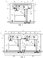
- a simplified example of a furnace with a single section is visible on the figure 1 .
- a furnace comprises several sections 100, 101, joined one after the other, ensuring continuity of the interior volume of said furnace.
- the sections 100, 101 are generally aligned, forming the longitudinal enclosure of said furnace.
- FIG. figure 2 A simplified example of a two-section furnace is shown in FIG. figure 2 .
- the heating device 1 comprises at least one conveyor 2 passing through said enclosure.
- a single conveyor 2 extends through said enclosure, from and to the outside, upstream and downstream relative to the direction of circulation of said batches along said heating device 1: a single conveyor 2 therefore transports the batches of products to make them enter the oven, pass through its enclosure and exit after treatment.
- the heating device 1 comprises a means 3 for heating said enclosure.
- a heating means 3 ensures the heating and circulation of air flow, so that it comes into contact with the batches of coated products to be treated.
- a heating means 3 comprises at least one heating module 30.
- a heating means 3 may comprise several heating modules 30, 31, in particular for the same section 100, making it possible to obtain different heat treatment conditions between several portions of said section.
- a heating means 3 comprises a heating module 30 for a first section 100 and another heating module 31 for a second section 101, as visible in the figure 2 , making it possible to obtain different treatment conditions in each of said sections 100,101.
- Said heating means 3 comprises at least one inlet 4 and at least one outlet 5.
- an inlet 40,41 and an outlet 50,51 are dedicated to each of them.
- each heating module 30, 31 comprises a heating block 6.
- a heating block 6 may comprise electrical resistors or at least one gas burner, heating the air which passes through each heating block 6.
- Each module 30,31 comprises at least one circuit 7 connecting at output 5,50,51 said heating block 6 and opening into the interior of said enclosure.
- each module 30, 31 comprises at least two circuits 70, 71.
- At least one first circuit 70 channels the flow of heated air towards at least one ramp 8, while at least one other circuit 71 channels the flow of heated air towards the conveyor 2.
- a ramp 8 can be constituted by the longitudinal internal wall of the oven.
- a ramp 8 can also be constituted by an independent element, then having a generally rectangular parallelepiped or trapezoidal shape, hollow and closed.
- Each ramp 8 is connected at output 5,50,51 to circuit 7, through which the heated air flow arrives.
- a ramp 8 may have a wall perforated with openings, in particular in the form of orifices through which the hot air is expelled and directed towards the interior of the volume of the enclosure.
- At least two ramps 8 are arranged vertically and parallel to each other, extending longitudinally in the direction of movement of the batches, over a portion of the length of the enclosure.
- Two ramps 8 are spaced transversely at an interval, on the one hand, allowing the batches to pass between said two ramps 8 and, on the other hand, at a determined distance from the side walls of the batches, in order to ensure heating and the formation of the constriction.
- a distributor 9 can be arranged at the outlet 5,50,51 of the heating block 6, in order to connect it and direct the flow of heated air towards one and/or the other of the circuits 70,71.
- Each circuit 7,70,71 may include portions provided with pipes, sheaths or conduits, hermetically connected to the different elements of the heating device 1.
- Each heating module 30, 31 comprises at least one means 10 for circulating a flow of air heated by said heating block 6 towards said circuit 7, in particular towards one and/or the other of the circuits 70, 71.
- a means 10 for circulating may comprise at least one turbine or at least one fan.
- Said means 10 for circulating comprises at least one air intake 11.
- an air intake 11 is connected to the inside of the enclosure.
- an air intake 11 comprises a suction mouth, open towards the inside of the enclosure, so as to draw air there so that it is circulated towards the corresponding heating block 6.
- an inlet 4,40,41 may correspond to a suction mouth of the heating means 3 and one of its heating modules 30,31, opening into the interior of the enclosure.
- the circulation of air flow is carried out in a looped manner, the air from the enclosure being sucked towards the heating means 3, in particular the heating modules 30, 31, by the circulation means 10 to pass through a corresponding heating block 6, before being sent to the circuit 7, in particular one and/or the other of the circuits 70, 71, to emerge via the ramps 8 and/or the conveyor 2 inside said enclosure.
- Such a circulation loop takes into consideration the internal volume of the oven enclosure, potentially open to the passages necessary for conveying the batches of products to be treated.
- the various elements can be joined or connected by pipes, in a hermetic manner, in order to allow such a loop circulation.
- the invention provides for recycling the air flow heated by the heating device 1, in particular its heating means 3.
- said heating device 1 comprises at least one recycling circuit 12 connecting at least said outlet 5, 50, 51 to said one inlet 4, 40, 41 of said heating means 3, in particular corresponding heating modules 30, 31.
- the recycling circuit 12 extends between one of the outlets 5, 50, 51 and one of the inlets 4, 40, 41 to limit the air flow sent to the circuits 7, 70, 71 and to channel it by limiting the circulation of the air flows inside the enclosure, preferably at the level of the conveyor 2. It is by making a connection as close as possible between the inlets 4,40,41 and outlets 5,50,51 of the heating device 1 that recycling makes it possible to avoid heat losses towards the bottom of the enclosure by keeping the flow of heated air circulating in the upper part around the heating means 3 and the heating modules 30,31.
- said recycling circuit 12 can connect the outlet 5 of a heating block 6 to said air inlet 11 of a circulation means 10 of said heating means 3.
- the recycling circuit 12 can comprise at least one pipe, connecting at one end the inlet 4,40,41 and at the opposite end the outlet 5,50,51, directly or not.
- the recycling circuit 12 can connect the outlet of a heating block 6 to the air evacuation at the outlet of the circulation means 10, namely the outlet of the turbine, in particular at the location connected to the corresponding heating block 6.
- a circulation means 10 may comprise at least one turbine which is provided with an air intake. Consequently, the recycling circuit 12 may open at said air intake. In this configuration, the recycling circuit 12 connects the outlet 5, 50, 51 to the inlet 4, 40, 41 via the air intake of the turbine, and not via the air intake 11.
- the recycling circuit 12 can connect the output 5,50,51 via the corresponding distributor 9.
- said oven is provided with at least a first section 100 and a second section 101 forming said enclosure.
- Said conveyor 2 passes through said first section 100 and second section 101.
- said heating means 3 comprises a first heating module 30 dedicated to said first section 100 and a second heating module 31 dedicated to said second section 101. Consequently, said recycling circuit 12 can connect the outlet 50 of the heating block 6 of the first heating module 30 to the inlet 41 of the circulation means 10 of said second heating module 31. In other words, the recycling takes place within the heating means 3, between its heating modules 30, 31. The heated air flow is then no longer sent to the first section 100, but redirected to the second section 101.
- said recycling circuit 12 may comprise a portion extending inside the enclosure of said oven. Said portion is provided with a volume 13 formed inside the enclosure by at least one internal wall 14. Preferably, said internal wall 14 is provided in the upper part of the enclosure, forming a false ceiling.
- the internal wall 14 may be perforated, allowing air to circulate with the enclosure, in particular in the form of suction from the enclosure.
- the heating means 3 can be located inside and/or outside the volume 13, namely elements constituting each heating module 30, 31 can be placed inside and/or outside said volume 13.
- the heating means 3 is arranged externally to the volume 13.
- the internal wall 14 then forms a portion of the recycling circuit 12.
- the heating means 3 is arranged inside the volume 13.
- the recycling circuit 12 is then delimited essentially by said volume 13, the air circulating inside said volume 13 and around the heating means 3.
- the invention aims at recycling the air flow heated by the heating means 3.
- the heating device 1 may comprise means for controlled closure of said circuit 7 and said recycling circuit 12.
- the controlled closure means make it possible to direct the air flow towards the circuit(s) 7, 70, 71 and/or towards the recycling circuit 12.
- the controlled shutter means may comprise shutters 15, 16 corresponding to the connections with the circuits 70, 71 and at least one recycling shutter 17 corresponding to the connection with the recycling circuit 12.
- the shutters 15, 16 and the recycling shutter 17 can be positioned at the junctions between, on the one hand, the distributor 9 and, on the other hand, the circuits 70, 71 and the recycling circuit 12.
- the shutters 15, 16 and the recycling shutter 17 are located at the corresponding inputs of the circuits 70, 71 and the recycling circuit 12, said inputs being connected to said distributor 9.
- the shutters 15, 16 and the shutter 17 may be of any type, in particular valves whose position totally or partially closes each of the circuits 70, 71 and the corresponding recycling circuit 12.
- control of the positions of the shutters 15, 16 and of the recycling shutter 17 is carried out by suitable means, in particular a dedicated control unit.
- a control unit may in particular comprise sensors, for example pressure and/or temperature, positioned at different locations of the heating device 1.
- the invention also relates to a method for circulating flow in a heating device 1, as previously described.
- the opening of the recycling circuit 12 is controlled.
- the opening of the recycling circuit 12 makes it possible to reduce the air flow sent to the circuit 7, in particular to one and the other of the circuits 70, 71 if they are open, or even completely to the recycling circuit 12 if they are completely closed.
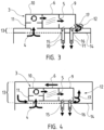
- Such a configuration is represented in the figures by solid arrows modeling the air flow redirected mainly towards the recycling circuit 12.
- the shutters 15, 16 are closed, while the recycling shutter 12 is partially open, modifying the circulation of the heated air flow.
- the suction of air from the enclosure can still be active through the air intake 11, but limited in flow rate because the majority of the flow is redirected towards the recycling circuit 12.
- each of the shutters 15, 16 and the recycling shutter 17 can be controlled alone in opening or closing, i.e. without modifying the positions of the others.
- the opening and the shuttering can be controlled in a synchronized manner.
- the opening of the shutter(s) 15, 16 respectively induces the closing of the recycling shutter 17, and vice versa.
- the opening or closing of the shutters 15,16 can be carried out simultaneously.
- the heating device 1 advantageously comprises a recycling circuit 12 for the heated air flow connecting at least one outlet 5, 50, 51 of the heating means 3 to at least one inlet 4, 40, 41 of said heating means 3.
- Such a circuit 12 is made so as to be able to significantly restrict, or even prevent, the circulation of heated air in the furnace enclosure, in particular in the lower part of the furnace, in which the conveyor 2 is located.
- the recycling circuit 12 is preferably isolated, at least partially, from the furnace enclosure.
- the recycling circuit 12 is distinct from at least one circuit 7, 70, 71 intended to supply hot air to the oven enclosure under conditions favorable to the shrinkage of the coating around the products.
- the hot air that is admitted at the end of the recycling circuit, at an inlet 4, 40, 41 of the heating means 3 can come from the oven enclosure only partially, or not at all. In other words, the air flow brought to an inlet 4, 40, 41 of the heating means 3 through the recycling circuit 12 cannot come solely from the oven enclosure.
- the recycling circuit 12 comprises at least one wall 14 making it possible to isolate the circuit 12 from the internal enclosure of the oven supplied with hot air by the circuit 7, 70, 71 as shown for example in Figures 3 and 4 .
- the recycling circuit 12 can also be closed by means of a pipe extending from at least one outlet 5,50,51 to at least one inlet 4,40,41 as shown for example in FIG. figure 1 .
- the invention makes it possible to recycle the air flow, preferably in the upper part of the enclosure of the heating device 1, limiting heat exchanges in the lower part, especially at the level of the conveyor 2.
- This recycling 12 makes it possible to save energy by limiting heat loss, while optimizing the operation of the heating device 1, as well as the conditioning installation.
- the invention may find a preferential, but in no way limiting, application in a specific operating mode of the wrapping packaging installation, for example a degraded operating mode of production or a start/stop, or in particular a standby mode. Therefore, the invention makes it possible in particular to accelerate and facilitate a return to production.
Landscapes
- Engineering & Computer Science (AREA)
- Mechanical Engineering (AREA)
- General Engineering & Computer Science (AREA)
- Environmental & Geological Engineering (AREA)
- Chemical & Material Sciences (AREA)
- Combustion & Propulsion (AREA)
- Drying Of Solid Materials (AREA)
- Basic Packing Technique (AREA)
- Auxiliary Devices For And Details Of Packaging Control (AREA)
Claims (11)
- Vorrichtung (1) zum Erhitzen von Chargen umhüllter Produkte, umfassend zumindest:- einen Ofen mit einem Innenraum;- mindestens einen Förderer (2), der durch den Raum verläuft;- ein Mittel (3) zum Erhitzen des Raums, wobei das Heizmittel (3) mindestens einen Einlass (4, 40, 41) und mindestens einen Auslass (5, 50, 51) umfasst;- wobei das Heizmittel (3) mindestens ein Heizmodul (30, 31) umfasst;- wobei jedes Heizmodul (30, 31) Folgendes umfasst: einen Heizblock (6), mindestens einen Kreislauf (7, 70, 71), der den Heizblock (6) mit dem Auslass (5, 50, 51) verbindet und in das Innere des Raums mündet, und mindestens ein Mittel (10) zum Umwälzen eines durch den Heizblock (6) erhitzten Luftstroms zum Kreislauf (7, 70, 71), wobei das Umwälzmittel (10) mindestens einen Lufteinlass (11) umfasst, wobei sich der Lufteinlass (11) am Einlass (4, 40, 41) befindet und mit dem Rauminneren verbunden ist;dadurch gekennzeichnet, dass sie mindestens einen Rückführungskreislauf (12) umfasst, der zumindest den Auslass (5, 50, 51) mit einem Einlass (4, 40, 41) des Heizmittels (3) verbindet, wobei der Rückführungskreislauf (12) von dem mindestens einen Kreislauf (7, 70, 71) getrennt ist.
- Heizvorrichtung (1) nach dem vorangehenden Anspruch, dadurch gekennzeichnet, dass der Rückführungskreislauf (12) den Auslass (5, 50, 51) eines Heizblocks (6) mit dem Lufteinlass (11) eines Umwälzmittels (10) des Heizmittels (3) verbindet.
- Heizvorrichtung (1) nach einem der vorangehenden Ansprüche, dadurch gekennzeichnet, dass:- der Ofen zumindest mit einem ersten Abschnitt (100) und einem zweiten Abschnitt (101) versehen ist, die den Raum bilden;- wobei der Förderer (2) durch den ersten Abschnitt (100) und den zweiten Abschnitt (101) verläuft;- wobei das Heizmittel (3) ein für den ersten Abschnitt (100) vorgesehenes erstes Heizmodul (30) und ein für den zweiten Abschnitt (101) vorgesehenes zweites Heizmodul (31) umfasst;und dadurch, dass:- der Rückführungskreislauf (12) den Auslass (50) des Heizblocks (6) des ersten Heizmoduls (20) mit dem Einlass (41) des Umwälzmittels (10) des zweiten Heizmoduls (31) verbindet.
- Heizvorrichtung (1) nach einem der vorangehenden Ansprüche, dadurch gekennzeichnet, dass ein Umwälzmittel (10) zumindest eine Turbine umfasst, die mit einem Lufteinlass versehen ist, und dass der Rückführungskreislauf (12) am Lufteinlass mündet.
- Heizvorrichtung (1) nach einem der vorangehenden Ansprüche, dadurch gekennzeichnet, dass sie Mittel zum gesteuerten Schließen des Kreislaufs (7, 70, 71) und des Rückführungskreislaufs (12) umfasst, wobei es die Mittel zum gesteuerten Schließen ermöglichen, den Luftstrom zu dem Kreislauf bzw. den Kreisläufen (7, 70, 71) und/oder zum Rückführungskreislauf (12) zu lenken.
- Heizvorrichtung (1) nach einem der vorangehenden Ansprüche, dadurch gekennzeichnet, dass der Rückführungskreislauf (12) einen Abschnitt umfasst, der sich innerhalb des Raums des Ofens erstreckt, wobei der Abschnitt mit einem Volumen versehen ist, das im Rauminneren durch mindestens eine Innenwand (14) gebildet ist.
- Heizvorrichtung (1) nach einem der vorangehenden Ansprüche, dadurch gekennzeichnet, dass der Rückführungskreislauf (12) über einen Verteiler (9) mit dem Auslass (5, 50, 51) verbunden ist.
- Anlage zum Verpacken von Produktchargen durch Bündeln, umfassend nacheinander zumindest:- eine Station zum Gruppieren der Produkte zu Chargen;- eine Station zum Umhüllen jeder der Chargen mit einer Schrumpffolie;- eine Station zum Erhitzen jeder Folie, die jede Charge umhüllt;- eine Station zum Abkühlen der Folie jeder Charge; dadurch gekennzeichnet, dass die Heizstation eine Vorrichtung (1) zum Erhitzen von Chargen umhüllter Produkte nach einem der vorangehenden Ansprüche umfasst.
- Verfahren zum Umwälzen von erhitzten Luftströmen in einer Heizvorrichtung (1) nach einem der Ansprüche 1 bis 7, dadurch gekennzeichnet, dass:- zumindest das Öffnen des Rückführungskreislaufs (12) gesteuert wird.
- Umwälzverfahren nach dem vorangehenden Anspruch, dadurch gekennzeichnet, dass das Schließen des mindestens einen Kreislaufs (7, 70, 71) am Auslass (5, 50, 51) des Heizblocks (6) gesteuert wird, um den dem mindestens einen Kreislauf (7, 70, 71) zugeführten Luftstrom zu begrenzen.
- Umwälzverfahren nach dem vorangehenden Anspruch, dadurch gekennzeichnet, dass das Öffnen und das Schließen synchron gesteuert werden.
Applications Claiming Priority (1)
| Application Number | Priority Date | Filing Date | Title |
|---|---|---|---|
| FR1904535A FR3095689B1 (fr) | 2019-04-30 | 2019-04-30 | Dispositif de chauffage, installation de conditionnement par fardelage avec un tel dispositif et procédé de mise en circulation de flux d'air chauffé dans ce dispositif. |
Publications (2)
| Publication Number | Publication Date |
|---|---|
| EP3734208A1 EP3734208A1 (de) | 2020-11-04 |
| EP3734208B1 true EP3734208B1 (de) | 2024-11-13 |
Family
ID=67956999
Family Applications (1)
| Application Number | Title | Priority Date | Filing Date |
|---|---|---|---|
| EP20172452.3A Active EP3734208B1 (de) | 2019-04-30 | 2020-04-30 | Heizvorrichtung, bündelungsverpackungsanlage mit einer solchen vorrichtung und verfahren zum zirkulierenlassen des angeheizten luftstroms in dieser vorrichtung |
Country Status (2)
| Country | Link |
|---|---|
| EP (1) | EP3734208B1 (de) |
| FR (1) | FR3095689B1 (de) |
Family Cites Families (7)
| Publication number | Priority date | Publication date | Assignee | Title |
|---|---|---|---|---|
| DE1262869B (de) * | 1962-05-29 | 1968-03-07 | Weldotron Corp | Heisslufttunnel |
| GB1062349A (en) * | 1965-03-17 | 1967-03-22 | Ici Ltd | Apparatus and method for packaging articles in heat shrinkable wrappers |
| AU1413566A (en) * | 1966-11-18 | 1969-03-13 | W. R. Grace Australia | Packaging |
| US3897671A (en) * | 1973-08-31 | 1975-08-05 | Comptex | Apparatus and method for covering a load on a pallet |
| ITMI20011825A1 (it) * | 2001-08-29 | 2003-03-01 | Smi Spa | Forno a tunnel di termoretrazione per la produzione di imballaggi in pellicole di materiale termoretraibile e procedimento di imballaggio re |
| FR2859704A1 (fr) * | 2003-09-11 | 2005-03-18 | Cetec Ind Conditionnement | Four de retractation destine plus particulierement a une fardeleuse |
| JP2010157633A (ja) * | 2008-12-27 | 2010-07-15 | Green Technologies Corp | リフロー装置 |
-
2019
- 2019-04-30 FR FR1904535A patent/FR3095689B1/fr active Active
-
2020
- 2020-04-30 EP EP20172452.3A patent/EP3734208B1/de active Active
Also Published As
| Publication number | Publication date |
|---|---|
| FR3095689B1 (fr) | 2024-01-12 |
| FR3095689A1 (fr) | 2020-11-06 |
| EP3734208A1 (de) | 2020-11-04 |
Similar Documents
| Publication | Publication Date | Title |
|---|---|---|
| EP1824659B1 (de) | Verfahren und anlage zur behälterherstellung | |
| EP2392442B2 (de) | Ofen für die Wärmebehandlung von Vorformligen und Steuerungsverfahren einer Abkühlvorrichtung mit Hilfe von Luft, die in einem solchen Ofen eingebaut ist | |
| EP3718910B1 (de) | Heizvorrichtung für lose von mischgut, und bündelungsverpackungsanlage für produktlose | |
| FR2570348A1 (fr) | Appareil pour contracter sous l'effet de la chaleur une pellicule de matiere plastique utilisee comme emballage | |
| WO2005068161A1 (fr) | Module de chauffage d'une preforme equipe d'un deflecteur d'air profile de facon aerodynamique et four comportant au moins un tel module | |
| EP0369888B1 (de) | Verfahren und Vorrichtung zum Sterilisieren einer Abfüllanlage für Nahrungsmittel oder pharmazeutische Produkte | |
| WO2015121122A1 (fr) | Installation de conditionnement thermique de préformes avec refroidissement d'une portion de la préforme par une lame d'air pulsé | |
| EP2872406B1 (de) | Wärmeschrumpfbare anlage mit mitteln zur regelung der temperatur im gehäuse der anlage | |
| EP3734208A1 (de) | Heizvorrichtung, bündelungsverpackungsanlage mit einer solchen vorrichtung und verfahren zum zirkulierenlassen des angeheizten luftstroms in dieser vorrichtung | |
| EP2872404B1 (de) | Wärmeschrumpfanlage mit einer wärmedispersionsvorrichtung als einheitliche anordnung | |
| EP0069007B1 (de) | Verfahren zur Herstellung von gestreckten und geblasenen Kunststoffbehältern und Vorrichtung zur Durchführung des Verfahrens | |
| EP3898427A1 (de) | Verfahren zum bündelverpacken von produktchargen, heizvorrichtung und anlage mit einer solchen vorrichtung | |
| EP1110042A1 (de) | Verfahren und vorrichtung zur kontinuierlichen kühlung von nahrungsmitteln | |
| FR3039445A3 (fr) | Module de transport de flux de soudure neuf et/ou recycle a la tremie de tete de la torche de soudage, reposant sur un principe d'alimentation par plusieurs modules d'etuvage et de conservation | |
| WO2011154450A1 (fr) | Ensemble pour la production de recipients au moyen d'une installation comportant un circuit de recyclage de l'air et procede de recyclage | |
| FR3090591A1 (fr) | Dispositif de conditionnement par fardelage et son procédé | |
| FR2588068A1 (fr) | Sechoir a tapis roulants | |
| FR2684318A1 (fr) | Sorbonne perfectionnee. | |
| FR2934196A1 (fr) | Four de conditionnement thermique de preformes en matiere thermoplastique de construction modulaire | |
| WO2013139658A1 (fr) | Dispositif de fabrication de récipient par soufflage dans lequel le gaz de soufflage détendu est dirigé vers un accessoire chaud pour le refroidir par ventilation | |
| FR2983427A1 (fr) | Dispositif de soufflage comportant une tuyere et un conduit d'alimentation formant un angle obtus | |
| FR3153606A1 (fr) | Unité de conditionnement thermique de préforme avec changement d’organe de préhension robotisé | |
| FR2463586A1 (fr) | Installation de murissage de fruits | |
| EP1077355A1 (de) | Einrichtung und Verfahren zur Behandlung von Produkten | |
| EP0516556B1 (de) | Verfahren zum Thermoverformen und eventuell weiteren Verpacken von Behältern und Maschine dafür |
Legal Events
| Date | Code | Title | Description |
|---|---|---|---|
| PUAI | Public reference made under article 153(3) epc to a published international application that has entered the european phase |
Free format text: ORIGINAL CODE: 0009012 |
|
| STAA | Information on the status of an ep patent application or granted ep patent |
Free format text: STATUS: THE APPLICATION HAS BEEN PUBLISHED |
|
| AK | Designated contracting states |
Kind code of ref document: A1 Designated state(s): AL AT BE BG CH CY CZ DE DK EE ES FI FR GB GR HR HU IE IS IT LI LT LU LV MC MK MT NL NO PL PT RO RS SE SI SK SM TR |
|
| AX | Request for extension of the european patent |
Extension state: BA ME |
|
| STAA | Information on the status of an ep patent application or granted ep patent |
Free format text: STATUS: REQUEST FOR EXAMINATION WAS MADE |
|
| 17P | Request for examination filed |
Effective date: 20210504 |
|
| RBV | Designated contracting states (corrected) |
Designated state(s): AL AT BE BG CH CY CZ DE DK EE ES FI FR GB GR HR HU IE IS IT LI LT LU LV MC MK MT NL NO PL PT RO RS SE SI SK SM TR |
|
| GRAP | Despatch of communication of intention to grant a patent |
Free format text: ORIGINAL CODE: EPIDOSNIGR1 |
|
| STAA | Information on the status of an ep patent application or granted ep patent |
Free format text: STATUS: GRANT OF PATENT IS INTENDED |
|
| INTG | Intention to grant announced |
Effective date: 20240603 |
|
| GRAS | Grant fee paid |
Free format text: ORIGINAL CODE: EPIDOSNIGR3 |
|
| GRAA | (expected) grant |
Free format text: ORIGINAL CODE: 0009210 |
|
| STAA | Information on the status of an ep patent application or granted ep patent |
Free format text: STATUS: THE PATENT HAS BEEN GRANTED |
|
| AK | Designated contracting states |
Kind code of ref document: B1 Designated state(s): AL AT BE BG CH CY CZ DE DK EE ES FI FR GB GR HR HU IE IS IT LI LT LU LV MC MK MT NL NO PL PT RO RS SE SI SK SM TR |
|
| RAP1 | Party data changed (applicant data changed or rights of an application transferred) |
Owner name: SIDEL PARTICIPATIONS |
|
| REG | Reference to a national code |
Ref country code: GB Ref legal event code: FG4D Free format text: NOT ENGLISH |
|
| REG | Reference to a national code |
Ref country code: CH Ref legal event code: EP |
|
| REG | Reference to a national code |
Ref country code: IE Ref legal event code: FG4D Free format text: LANGUAGE OF EP DOCUMENT: FRENCH |
|
| REG | Reference to a national code |
Ref country code: DE Ref legal event code: R096 Ref document number: 602020041176 Country of ref document: DE |
|
| P01 | Opt-out of the competence of the unified patent court (upc) registered |
Free format text: CASE NUMBER: APP_60956/2024 Effective date: 20241113 |
|
| REG | Reference to a national code |
Ref country code: LT Ref legal event code: MG9D |
|
| REG | Reference to a national code |
Ref country code: NL Ref legal event code: MP Effective date: 20241113 |
|
| PG25 | Lapsed in a contracting state [announced via postgrant information from national office to epo] |
Ref country code: PT Free format text: LAPSE BECAUSE OF FAILURE TO SUBMIT A TRANSLATION OF THE DESCRIPTION OR TO PAY THE FEE WITHIN THE PRESCRIBED TIME-LIMIT Effective date: 20250313 Ref country code: IS Free format text: LAPSE BECAUSE OF FAILURE TO SUBMIT A TRANSLATION OF THE DESCRIPTION OR TO PAY THE FEE WITHIN THE PRESCRIBED TIME-LIMIT Effective date: 20250313 Ref country code: HR Free format text: LAPSE BECAUSE OF FAILURE TO SUBMIT A TRANSLATION OF THE DESCRIPTION OR TO PAY THE FEE WITHIN THE PRESCRIBED TIME-LIMIT Effective date: 20241113 |
|
| PG25 | Lapsed in a contracting state [announced via postgrant information from national office to epo] |
Ref country code: NL Free format text: LAPSE BECAUSE OF FAILURE TO SUBMIT A TRANSLATION OF THE DESCRIPTION OR TO PAY THE FEE WITHIN THE PRESCRIBED TIME-LIMIT Effective date: 20241113 Ref country code: FI Free format text: LAPSE BECAUSE OF FAILURE TO SUBMIT A TRANSLATION OF THE DESCRIPTION OR TO PAY THE FEE WITHIN THE PRESCRIBED TIME-LIMIT Effective date: 20241113 |
|
| REG | Reference to a national code |
Ref country code: AT Ref legal event code: MK05 Ref document number: 1741960 Country of ref document: AT Kind code of ref document: T Effective date: 20241113 |
|
| PG25 | Lapsed in a contracting state [announced via postgrant information from national office to epo] |
Ref country code: BG Free format text: LAPSE BECAUSE OF FAILURE TO SUBMIT A TRANSLATION OF THE DESCRIPTION OR TO PAY THE FEE WITHIN THE PRESCRIBED TIME-LIMIT Effective date: 20241113 |
|
| PG25 | Lapsed in a contracting state [announced via postgrant information from national office to epo] |
Ref country code: ES Free format text: LAPSE BECAUSE OF FAILURE TO SUBMIT A TRANSLATION OF THE DESCRIPTION OR TO PAY THE FEE WITHIN THE PRESCRIBED TIME-LIMIT Effective date: 20241113 |
|
| PG25 | Lapsed in a contracting state [announced via postgrant information from national office to epo] |
Ref country code: NO Free format text: LAPSE BECAUSE OF FAILURE TO SUBMIT A TRANSLATION OF THE DESCRIPTION OR TO PAY THE FEE WITHIN THE PRESCRIBED TIME-LIMIT Effective date: 20250213 |
|
| PG25 | Lapsed in a contracting state [announced via postgrant information from national office to epo] |
Ref country code: AT Free format text: LAPSE BECAUSE OF FAILURE TO SUBMIT A TRANSLATION OF THE DESCRIPTION OR TO PAY THE FEE WITHIN THE PRESCRIBED TIME-LIMIT Effective date: 20241113 Ref country code: GR Free format text: LAPSE BECAUSE OF FAILURE TO SUBMIT A TRANSLATION OF THE DESCRIPTION OR TO PAY THE FEE WITHIN THE PRESCRIBED TIME-LIMIT Effective date: 20250214 Ref country code: LV Free format text: LAPSE BECAUSE OF FAILURE TO SUBMIT A TRANSLATION OF THE DESCRIPTION OR TO PAY THE FEE WITHIN THE PRESCRIBED TIME-LIMIT Effective date: 20241113 |
|
| PG25 | Lapsed in a contracting state [announced via postgrant information from national office to epo] |
Ref country code: PL Free format text: LAPSE BECAUSE OF FAILURE TO SUBMIT A TRANSLATION OF THE DESCRIPTION OR TO PAY THE FEE WITHIN THE PRESCRIBED TIME-LIMIT Effective date: 20241113 |
|
| PG25 | Lapsed in a contracting state [announced via postgrant information from national office to epo] |
Ref country code: RS Free format text: LAPSE BECAUSE OF FAILURE TO SUBMIT A TRANSLATION OF THE DESCRIPTION OR TO PAY THE FEE WITHIN THE PRESCRIBED TIME-LIMIT Effective date: 20250213 |
|
| PG25 | Lapsed in a contracting state [announced via postgrant information from national office to epo] |
Ref country code: SM Free format text: LAPSE BECAUSE OF FAILURE TO SUBMIT A TRANSLATION OF THE DESCRIPTION OR TO PAY THE FEE WITHIN THE PRESCRIBED TIME-LIMIT Effective date: 20241113 |
|
| PGFP | Annual fee paid to national office [announced via postgrant information from national office to epo] |
Ref country code: DE Payment date: 20250319 Year of fee payment: 6 |
|
| PG25 | Lapsed in a contracting state [announced via postgrant information from national office to epo] |
Ref country code: DK Free format text: LAPSE BECAUSE OF FAILURE TO SUBMIT A TRANSLATION OF THE DESCRIPTION OR TO PAY THE FEE WITHIN THE PRESCRIBED TIME-LIMIT Effective date: 20241113 |
|
| PG25 | Lapsed in a contracting state [announced via postgrant information from national office to epo] |
Ref country code: EE Free format text: LAPSE BECAUSE OF FAILURE TO SUBMIT A TRANSLATION OF THE DESCRIPTION OR TO PAY THE FEE WITHIN THE PRESCRIBED TIME-LIMIT Effective date: 20241113 |
|
| PG25 | Lapsed in a contracting state [announced via postgrant information from national office to epo] |
Ref country code: RO Free format text: LAPSE BECAUSE OF FAILURE TO SUBMIT A TRANSLATION OF THE DESCRIPTION OR TO PAY THE FEE WITHIN THE PRESCRIBED TIME-LIMIT Effective date: 20241113 |
|
| PG25 | Lapsed in a contracting state [announced via postgrant information from national office to epo] |
Ref country code: SK Free format text: LAPSE BECAUSE OF FAILURE TO SUBMIT A TRANSLATION OF THE DESCRIPTION OR TO PAY THE FEE WITHIN THE PRESCRIBED TIME-LIMIT Effective date: 20241113 |
|
| PG25 | Lapsed in a contracting state [announced via postgrant information from national office to epo] |
Ref country code: CZ Free format text: LAPSE BECAUSE OF FAILURE TO SUBMIT A TRANSLATION OF THE DESCRIPTION OR TO PAY THE FEE WITHIN THE PRESCRIBED TIME-LIMIT Effective date: 20241113 |
|
| REG | Reference to a national code |
Ref country code: DE Ref legal event code: R097 Ref document number: 602020041176 Country of ref document: DE |
|
| PG25 | Lapsed in a contracting state [announced via postgrant information from national office to epo] |
Ref country code: SE Free format text: LAPSE BECAUSE OF FAILURE TO SUBMIT A TRANSLATION OF THE DESCRIPTION OR TO PAY THE FEE WITHIN THE PRESCRIBED TIME-LIMIT Effective date: 20241113 |
|
| PLBE | No opposition filed within time limit |
Free format text: ORIGINAL CODE: 0009261 |
|
| STAA | Information on the status of an ep patent application or granted ep patent |
Free format text: STATUS: NO OPPOSITION FILED WITHIN TIME LIMIT |
|
| 26N | No opposition filed |
Effective date: 20250814 |
|
| REG | Reference to a national code |
Ref country code: CH Ref legal event code: H13 Free format text: ST27 STATUS EVENT CODE: U-0-0-H10-H13 (AS PROVIDED BY THE NATIONAL OFFICE) Effective date: 20251125 |
|
| PG25 | Lapsed in a contracting state [announced via postgrant information from national office to epo] |
Ref country code: LU Free format text: LAPSE BECAUSE OF NON-PAYMENT OF DUE FEES Effective date: 20250430 |
|
| PG25 | Lapsed in a contracting state [announced via postgrant information from national office to epo] |
Ref country code: MC Free format text: LAPSE BECAUSE OF FAILURE TO SUBMIT A TRANSLATION OF THE DESCRIPTION OR TO PAY THE FEE WITHIN THE PRESCRIBED TIME-LIMIT Effective date: 20241113 |
|
| GBPC | Gb: european patent ceased through non-payment of renewal fee |
Effective date: 20250430 |
|
| REG | Reference to a national code |
Ref country code: BE Ref legal event code: MM Effective date: 20250430 |
|
| PG25 | Lapsed in a contracting state [announced via postgrant information from national office to epo] |
Ref country code: GB Free format text: LAPSE BECAUSE OF NON-PAYMENT OF DUE FEES Effective date: 20250430 |
|
| PG25 | Lapsed in a contracting state [announced via postgrant information from national office to epo] |
Ref country code: BE Free format text: LAPSE BECAUSE OF NON-PAYMENT OF DUE FEES Effective date: 20250430 |
|
| PG25 | Lapsed in a contracting state [announced via postgrant information from national office to epo] |
Ref country code: CH Free format text: LAPSE BECAUSE OF NON-PAYMENT OF DUE FEES Effective date: 20250430 |
|
| PG25 | Lapsed in a contracting state [announced via postgrant information from national office to epo] |
Ref country code: IE Free format text: LAPSE BECAUSE OF NON-PAYMENT OF DUE FEES Effective date: 20250430 |
|
| PGFP | Annual fee paid to national office [announced via postgrant information from national office to epo] |
Ref country code: IT Payment date: 20260319 Year of fee payment: 7 |
|
| PGFP | Annual fee paid to national office [announced via postgrant information from national office to epo] |
Ref country code: FR Payment date: 20260319 Year of fee payment: 7 |