EP3734164A1 - Radiateur électrique - Google Patents
Radiateur électrique Download PDFInfo
- Publication number
- EP3734164A1 EP3734164A1 EP20170742.9A EP20170742A EP3734164A1 EP 3734164 A1 EP3734164 A1 EP 3734164A1 EP 20170742 A EP20170742 A EP 20170742A EP 3734164 A1 EP3734164 A1 EP 3734164A1
- Authority
- EP
- European Patent Office
- Prior art keywords
- base body
- web
- clamping body
- heating resistor
- clamping
- Prior art date
- Legal status (The legal status is an assumption and is not a legal conclusion. Google has not performed a legal analysis and makes no representation as to the accuracy of the status listed.)
- Pending
Links
Images

Classifications
-
- F—MECHANICAL ENGINEERING; LIGHTING; HEATING; WEAPONS; BLASTING
- F24—HEATING; RANGES; VENTILATING
- F24H—FLUID HEATERS, e.g. WATER OR AIR HEATERS, HAVING HEAT-GENERATING MEANS, e.g. HEAT PUMPS, IN GENERAL
- F24H3/00—Air heaters
- F24H3/002—Air heaters using electric energy supply
-
- F—MECHANICAL ENGINEERING; LIGHTING; HEATING; WEAPONS; BLASTING
- F24—HEATING; RANGES; VENTILATING
- F24C—DOMESTIC STOVES OR RANGES ; DETAILS OF DOMESTIC STOVES OR RANGES, OF GENERAL APPLICATION
- F24C7/00—Stoves or ranges heated by electric energy
- F24C7/06—Arrangement or mounting of electric heating elements
- F24C7/062—Arrangement or mounting of electric heating elements on stoves
-
- F—MECHANICAL ENGINEERING; LIGHTING; HEATING; WEAPONS; BLASTING
- F24—HEATING; RANGES; VENTILATING
- F24D—DOMESTIC- OR SPACE-HEATING SYSTEMS, e.g. CENTRAL HEATING SYSTEMS; DOMESTIC HOT-WATER SUPPLY SYSTEMS; ELEMENTS OR COMPONENTS THEREFOR
- F24D13/00—Electric heating systems
- F24D13/04—Electric heating systems using electric heating of heat-transfer fluid in separate units of the system
-
- F—MECHANICAL ENGINEERING; LIGHTING; HEATING; WEAPONS; BLASTING
- F24—HEATING; RANGES; VENTILATING
- F24H—FLUID HEATERS, e.g. WATER OR AIR HEATERS, HAVING HEAT-GENERATING MEANS, e.g. HEAT PUMPS, IN GENERAL
- F24H3/00—Air heaters
- F24H3/002—Air heaters using electric energy supply
- F24H3/004—Air heaters using electric energy supply with a closed circuit for a heat transfer liquid
-
- F—MECHANICAL ENGINEERING; LIGHTING; HEATING; WEAPONS; BLASTING
- F24—HEATING; RANGES; VENTILATING
- F24H—FLUID HEATERS, e.g. WATER OR AIR HEATERS, HAVING HEAT-GENERATING MEANS, e.g. HEAT PUMPS, IN GENERAL
- F24H9/00—Details
- F24H9/18—Arrangement or mounting of grates or heating means
- F24H9/1854—Arrangement or mounting of grates or heating means for air heaters
- F24H9/1863—Arrangement or mounting of electric heating means
-
- H—ELECTRICITY
- H05—ELECTRIC TECHNIQUES NOT OTHERWISE PROVIDED FOR
- H05B—ELECTRIC HEATING; ELECTRIC LIGHT SOURCES NOT OTHERWISE PROVIDED FOR; CIRCUIT ARRANGEMENTS FOR ELECTRIC LIGHT SOURCES, IN GENERAL
- H05B3/00—Ohmic-resistance heating
- H05B3/20—Heating elements having extended surface area substantially in a two-dimensional plane, e.g. plate-heater
- H05B3/22—Heating elements having extended surface area substantially in a two-dimensional plane, e.g. plate-heater non-flexible
- H05B3/24—Heating elements having extended surface area substantially in a two-dimensional plane, e.g. plate-heater non-flexible heating conductor being self-supporting
-
- H—ELECTRICITY
- H05—ELECTRIC TECHNIQUES NOT OTHERWISE PROVIDED FOR
- H05B—ELECTRIC HEATING; ELECTRIC LIGHT SOURCES NOT OTHERWISE PROVIDED FOR; CIRCUIT ARRANGEMENTS FOR ELECTRIC LIGHT SOURCES, IN GENERAL
- H05B2203/00—Aspects relating to Ohmic resistive heating covered by group H05B3/00
- H05B2203/02—Heaters using heating elements having a positive temperature coefficient
-
- H—ELECTRICITY
- H05—ELECTRIC TECHNIQUES NOT OTHERWISE PROVIDED FOR
- H05B—ELECTRIC HEATING; ELECTRIC LIGHT SOURCES NOT OTHERWISE PROVIDED FOR; CIRCUIT ARRANGEMENTS FOR ELECTRIC LIGHT SOURCES, IN GENERAL
- H05B2214/00—Aspects relating to resistive heating, induction heating and heating using microwaves, covered by groups H05B3/00, H05B6/00
- H05B2214/02—Heaters specially designed for de-icing or protection against icing
-
- Y—GENERAL TAGGING OF NEW TECHNOLOGICAL DEVELOPMENTS; GENERAL TAGGING OF CROSS-SECTIONAL TECHNOLOGIES SPANNING OVER SEVERAL SECTIONS OF THE IPC; TECHNICAL SUBJECTS COVERED BY FORMER USPC CROSS-REFERENCE ART COLLECTIONS [XRACs] AND DIGESTS
- Y02—TECHNOLOGIES OR APPLICATIONS FOR MITIGATION OR ADAPTATION AGAINST CLIMATE CHANGE
- Y02B—CLIMATE CHANGE MITIGATION TECHNOLOGIES RELATED TO BUILDINGS, e.g. HOUSING, HOUSE APPLIANCES OR RELATED END-USER APPLICATIONS
- Y02B30/00—Energy efficient heating, ventilation or air conditioning [HVAC]
Definitions
- the present invention relates to an electric radiator according to the preamble of claim 1.
- the radiator is used to heat rooms or parts of rooms in a building and can in particular be designed as a designer radiator or a radiator.
- radiators are generally known. They can be used as purely electrically operated radiators, to which only electrical energy is supplied and converted into heat by means of an electrical heating resistor, or as combined radiators, which are connected to a central heating system on the one hand and are flowed through by a heating medium heated by this, and an additional one on the other have an electrical heating element for converting electrical energy into heat.
- the electrical heating element is usually used as additional heating for the radiator, which enables electrical heating, especially in the transition period from spring to autumn, when the central heating system is already or is still switched off.
- a combined heating element with flow and return connections for a circulating heating medium in which an electric heating rod is arranged in a distributor pipe or collecting tube of the heating element, is for example from the DE 20 2006 007 968 U1 known.
- the electrical heating element comes into direct contact with the circulating heating medium.
- a heating system in which an electrically operated surface heating element is attached to a heating element through which a heating medium can in particular flow.
- the electrically operated surface heating element is attached via a protective cover and a housing cover and retaining elements to the rear of the curved heating element.
- a combined radiator which is at least partially filled with a heating medium or through which a heating medium can flow, and to which an electrical heating element is attached on the outside.
- the electrical heating element can be attached either cohesively, in particular by gluing, or non-positively via clamping means.
- An attachment carried out by gluing can be problematic at higher temperatures or on certain surfaces, for example with painted base bodies.
- the holding force of the adhesive connection can decrease over time. Separation of the electrical heating resistor from the base body, for example during a repair or at the end of the life of the radiator, in the case of an adhesive connection, is associated with a considerable amount of work.
- the object of the present invention is therefore to provide an electrical heating element with an improved force-locking attachment of the electrical heating resistor to the base body.
- the base element has a convexly curved contact surface against which the electrical heating resistance is pressed by the clamping element, and / or that the clamping body has a convexly curved contact surface which is pressed against the electrical heating resistor.
- An essential advantage of the embodiment according to the invention is that the electrical heating resistor, which covers only a partial area of the surface of the base body and therefore has a very high heating power density, rests optimally on the contact surface of the base body and is advantageously held securely against it over its entire extent .
- clamping body also rests optimally on the rear side of the electrical heating resistor facing away from the base body, so that with a material that conducts heat well Clamping body heat can also be optimally dissipated from the back of the electrical heating resistor and advantageously transferred to the base body.
- the electrical heating resistor is advantageously held on the base body of the heating body only by the clamping body, so that no further fastening means are required.
- clamping body is held on the base body in a form-fitting and force-fitting manner. This ensures a particularly simple and quick assembly.
- a first region of the clamping body engages behind a first projection which the base body has.
- the clamping body preferably rests against the first projection with the first region protruding laterally beyond the contact surface in a direction running at least approximately perpendicular to the contact surface. In this way, the clamping body can be held on the base body in a particularly simple manner.
- a second region of the clamping body also engages behind a second projection, which the base body also has.
- the clamping body preferably rests against the second projection with the second region protruding laterally beyond the contact surface in a direction running at least approximately perpendicular to the contact surface.
- the second projection of the clamping body is advantageously located on the side opposite the first projection with respect to the contact surface for the electrical heating resistor.
- the first projection and / or the second projection can each be formed by a longitudinally extending rib of the base body which protrudes laterally in the direction of the contact surface.
- the base body has a third projection or a contact area against which the clamping body rests in a direction running at least approximately parallel or tangential to the contact surface while it engages behind the first and second projections. In this way, an unintentional lateral displacement of the clamping body can be prevented, so that the engagement of the two projections from behind and thus the non-positive fastening is reliably secured.
- the base body has at least one chamber filled with a fluid and / or at least one channel through which a heating fluid can flow and which is connected to a flow connection and a return connection of the heater.
- the base body is a metallic profile body.
- projections for attaching the clamping body can be formed in a particularly simple manner.
- the base body preferably consists of an extruded aluminum profile, which is characterized by good thermal conductivity and low weight.
- the clamping body be formed by a sheet metal, in particular by an elastic aluminum sheet.
- the clamping body can well have the resilient properties (elasticity) required for applying the clamping force.
- the heat emerging from the rear of the electrical heating resistor can also be absorbed particularly well via a sheet of metal that conducts heat well, such as aluminum Base body are guided so that the electrical heating resistor is quasi cooled by the clamping body.
- the clamping body is preferably formed by an elongated elastic sheet metal strip or an elongated elastic sheet metal profile.
- the clamping body has a pressure web forming a pressure surface and at least one holding web angled therefrom.
- the pressure bar can have the elasticity required for pressing the heating resistor and preferably be convexly curved.
- the holding bar in particular a free edge of the holding bar, can form a first area that engages behind a first projection of the base body, while the pressure bar, in particular a free edge of the pressure bar, forms a second area that engages behind a second projection of the base body.
- the holding web can come to rest against a third projection or an abutment area of the base body, so that the clamping body is secured against unintentional lateral displacement and the holding web and the pressure web reliably engage behind the two projections of the base body.
- the holding web is preferably angled from the pressure web at an angle of 90 °.
- the holding web has at least one transverse slot which divides the holding web into at least two holding flaps.
- the transverse slot advantageously runs transversely to the longitudinal extension of the sheet metal profile. In this way, the retaining flaps of the retaining web can be brought particularly easily behind a projection of the base body.
- the holding web has a plurality of transverse slots which subdivide the holding web into a corresponding plurality of holding prongs.
- clamping body Preferably, only a single clamping body is provided. Alternatively, however, two or more clamping bodies can also be arranged for pressing the electrical heating resistor against the base body.
- the heating resistor is designed in the form of a flat strip with a contact surface pressed against the base body.
- the electrical heating resistor is flexible, that is to say consists of an elastic, that is to say easily mechanically deformable material. This enables optimal and full-surface contact of the heating resistor on the contact surface of the base body when the clamping body is pressed against it.
- the heating resistor is surrounded by a plastic jacket.
- the sheath also advantageously consists of an elastic, that is to say easily flexible or deformable plastic.
- the electrical heating resistor is advantageously a PTC heating element.
- PTC heating elements regulate their power automatically when a certain limit temperature is reached by increasing their resistance, which is why they can be used particularly well for heating applications.
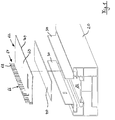
- the Figures 1 and 2 show an electric heater 10, which is intended to be used as a radiator in a building for heating a room. For this purpose, it can be attached with its rear side R to a building wall, not shown here. It comprises three main components, which are formed by a base body 20, an electrical heating resistor 40 and a clamping body 60. In the fully assembled state, the electrical heating resistor 40 is exclusively non-positively attached to the base body 20 by being pressed firmly against the base body by the clamping body 60 ( Figure 2 ).
- the base body 20 here consists of an extruded aluminum profile, the substantially rectangular cross section of which in Figure 2 is shown by way of example.
- it includes a contact surface 22 for the heating resistor 40, which is offset from the rear side R in the direction of the front side V into the aluminum profile.
- the base body 20 With respect to an inner central web 24 running perpendicular to the front side V, the base body 20 is designed to be axially symmetrical, the contact surface 22 also being located centrally or axially symmetrically to the central web 24.
- the contact surface 22 is thus in each case on both longitudinal sides of a protruding towards the rear side R.
- Profile area 26 surround. According to the present invention, the contact surface 22 has a profile that is slightly convex towards the rear side R.
- a first web 28 projects in the direction of the respective other profile area 26, which is continued on the inside by a longer web 30 which is angled by 90 ° and protrudes rearward behind the rear side R.
- the two webs 28 and 30 each form an L-shaped cross section on the mutually facing sides of the two profile areas 26.
- a second web 32 and, slightly above the contact surface 22 a third web 34 follow in the direction of the contact surface 22 offset inward. These webs 32 and 34 extend laterally, parallel to the rear side R in the direction of the respective other profile area 26.
- the second web 32 is narrower than the first web 28 and the third web 34 is narrower than the second web 32.
- the mutually facing webs 28 and 34 each form a first and a second projection, behind each of which a side edge of the clamping body 60 can be clamped in order to press the heating resistor 40 against the contact surface 22.
- the clamping body 60 is formed by an elongated aluminum sheet which has good thermal conductivity. It comprises a flat pressure web 62 and a flat holding web 64 angled therefrom by 90 °, so that the clamping body 60 overall has an L-shaped cross section.
- the pressure web 62 is made wider than the holding web 64, wherein it can be bent in a slightly resilient manner in the transverse direction.
- the pressure web 62 forms a pressure surface that rests against the electrical heating resistor 40 in the fully assembled state.
- the holding web 64 contains a plurality of transverse slots 66 which are oriented transversely to the longitudinal extension of the sheet metal profile and which divide the holding web 64 into a plurality of holding prongs 68.
- the free end edges on the one hand of the pressure web 62 and on the other hand of the holding web 64 or the holding prongs 68 each engage behind a projection formed by a web 28 and 34 in the fully assembled state.
- the holding web 64 Due to the subdivision of the holding web 64 into the plurality of holding prongs 68, these can be particularly easily pressed one after the other behind the projection formed by a web 28 after the free end edge 70 of the pressure web 62 has previously been placed on the opposite side under the web 34.
- the pressure web 62 is arched according to the convex surface of the contact surface 22 and thereby builds up the clamping force required to hold the heating resistor 40 in a non-positive manner.
- the arching of the pressure web 62 caused in this way causes the holding prongs 68 protruding at right angles from the area of the pressure web 62 protruding laterally over the contact surface 22 behind the projection formed by the web 28, where they are pressed with a central area against the rib 32 of the base body Hit 20. Since the free end edge of the pressure web 62 on the opposite side of the contact surface 22 at the same time rest against a profile wall of the base body 20 lying below the rib 34, an unintentional lateral displacement of the clamping body 60 cannot occur, so that the clamping body 60 and thus also the electrical heating resistor 40 is securely fixed to the base body 20.
- the electrical heating resistor 40 designed here as a self-regulating dynamic PTC heating element, is designed in the form of a flat strip, the length of which corresponds at least essentially to the length of the base body 20 and the clamping body 60. It is surrounded on both sides by a plastic casing which, like the electrical heating resistor 40 itself, consists of an elastic, slightly mechanically flexible material. On In this way, the electrical heating resistor 40 with the plastic cover can be flexibly deformed and easily adapt over the entire surface to the curvature given by the convex contact surface 22.
- the holding prongs 68 hold themselves well behind the projection formed by the web 28.
Landscapes
- Engineering & Computer Science (AREA)
- Chemical & Material Sciences (AREA)
- Combustion & Propulsion (AREA)
- Mechanical Engineering (AREA)
- General Engineering & Computer Science (AREA)
- Physics & Mathematics (AREA)
- Thermal Sciences (AREA)
- Air-Conditioning For Vehicles (AREA)
Applications Claiming Priority (1)
| Application Number | Priority Date | Filing Date | Title |
|---|---|---|---|
| DE102019110622.2A DE102019110622A1 (de) | 2019-04-24 | 2019-04-24 | Elektrischer Heizkörper |
Publications (1)
| Publication Number | Publication Date |
|---|---|
| EP3734164A1 true EP3734164A1 (fr) | 2020-11-04 |
Family
ID=70390940
Family Applications (1)
| Application Number | Title | Priority Date | Filing Date |
|---|---|---|---|
| EP20170742.9A Pending EP3734164A1 (fr) | 2019-04-24 | 2020-04-21 | Radiateur électrique |
Country Status (2)
| Country | Link |
|---|---|
| EP (1) | EP3734164A1 (fr) |
| DE (1) | DE102019110622A1 (fr) |
Cited By (1)
| Publication number | Priority date | Publication date | Assignee | Title |
|---|---|---|---|---|
| US11892175B2 (en) | 2017-11-16 | 2024-02-06 | Lancey Energy Storage | Heating appliance with a built-in battery arranged in the incoming fresh air flow |
Citations (7)
| Publication number | Priority date | Publication date | Assignee | Title |
|---|---|---|---|---|
| DE2738036A1 (de) * | 1976-08-23 | 1978-03-02 | Roland Keller | Heizelement fuer die raumheizung |
| DE29918763U1 (de) | 1998-10-27 | 2000-01-27 | Joh. Vaillant Gmbh U. Co, 42859 Remscheid | Heizkörper mit einer im wesentlichen mäanderförmigen Wasserführung |
| EP1584873A1 (fr) | 2004-04-05 | 2005-10-12 | Zehnder Verkaufs- und Verwaltungs AG | Système de chauffage |
| DE202006007968U1 (de) | 2006-05-11 | 2006-07-27 | Kermi Gmbh | Heizkörper mit elektrischem Heizstab |
| DE102005002840A1 (de) | 2005-01-20 | 2006-08-03 | The Heating Company Bvba | Heizkörper mit einem äußeren elektrischen Heizelement |
| DE102008043893A1 (de) * | 2007-11-26 | 2009-05-28 | Denso Corp., Kariya-shi | Elektrische Heizvorrichtung |
| EP2251612A1 (fr) * | 2009-05-04 | 2010-11-17 | Atlantic Industrie | Radiateur électrique à fluide caloporteur formé d'éléments modulaires moulés |
Family Cites Families (3)
| Publication number | Priority date | Publication date | Assignee | Title |
|---|---|---|---|---|
| DE2062442A1 (de) * | 1970-12-18 | 1972-06-29 | Turk & Hillinger KG, 7200 Tuttlingen | Elektrisch beheizte Verkleidung für Heizgeräte od.dergl |
| DE3108928C2 (de) * | 1981-03-10 | 1984-08-09 | Valentino-Valerio 5760 Arnsberg Giacosa | Heizkörper für Raumzentralheizungen |
| FR2947614A1 (fr) * | 2009-07-02 | 2011-01-07 | Alain Galmes | Radiateur convecteur + accumulation en profils aluminium electrique et a eau chaude |
-
2019
- 2019-04-24 DE DE102019110622.2A patent/DE102019110622A1/de active Pending
-
2020
- 2020-04-21 EP EP20170742.9A patent/EP3734164A1/fr active Pending
Patent Citations (7)
| Publication number | Priority date | Publication date | Assignee | Title |
|---|---|---|---|---|
| DE2738036A1 (de) * | 1976-08-23 | 1978-03-02 | Roland Keller | Heizelement fuer die raumheizung |
| DE29918763U1 (de) | 1998-10-27 | 2000-01-27 | Joh. Vaillant Gmbh U. Co, 42859 Remscheid | Heizkörper mit einer im wesentlichen mäanderförmigen Wasserführung |
| EP1584873A1 (fr) | 2004-04-05 | 2005-10-12 | Zehnder Verkaufs- und Verwaltungs AG | Système de chauffage |
| DE102005002840A1 (de) | 2005-01-20 | 2006-08-03 | The Heating Company Bvba | Heizkörper mit einem äußeren elektrischen Heizelement |
| DE202006007968U1 (de) | 2006-05-11 | 2006-07-27 | Kermi Gmbh | Heizkörper mit elektrischem Heizstab |
| DE102008043893A1 (de) * | 2007-11-26 | 2009-05-28 | Denso Corp., Kariya-shi | Elektrische Heizvorrichtung |
| EP2251612A1 (fr) * | 2009-05-04 | 2010-11-17 | Atlantic Industrie | Radiateur électrique à fluide caloporteur formé d'éléments modulaires moulés |
Cited By (1)
| Publication number | Priority date | Publication date | Assignee | Title |
|---|---|---|---|---|
| US11892175B2 (en) | 2017-11-16 | 2024-02-06 | Lancey Energy Storage | Heating appliance with a built-in battery arranged in the incoming fresh air flow |
Also Published As
| Publication number | Publication date |
|---|---|
| DE102019110622A1 (de) | 2020-10-29 |
Similar Documents
| Publication | Publication Date | Title |
|---|---|---|
| EP1931176B1 (fr) | Dispositif de chauffage électrique et son procédé de fabrication | |
| EP1327834B1 (fr) | Elément de radiation pour appareil de chauffage | |
| EP1847786B1 (fr) | Appareil de chauffage | |
| DE102006055216B4 (de) | Heizeinrichtung für Dieselkraftstoff und beheizbares Dieselfiltersystem | |
| DE102006018151B4 (de) | Heizgerät | |
| DE112016000688B4 (de) | Elektrische Heizvorrichtung | |
| EP2298582A1 (fr) | Dispositif de chauffage électrique et son procédé de fabrication | |
| EP0379874A1 (fr) | Dispositif de fixation pour éléments PTC | |
| DE19848169A1 (de) | Vorrichtung zum Beheizen von Innenräumen, insbesondere von Kraftfahrzeugen | |
| EP3734164A1 (fr) | Radiateur électrique | |
| DE202005020765U1 (de) | Vorrichtung zum Übertragen von Wärme von einem Heizelement auf Umgebungsluft | |
| EP2012390A2 (fr) | Pince de mise à la terre destinée à l'équilibrage du potentiel de canaux de câblage | |
| EP3378279B1 (fr) | Riadateur pour chauffage electrique et chauffage electrique | |
| EP2266823A1 (fr) | Dispositif de chauffage électrique | |
| EP3856568A1 (fr) | Raccord de dilatation pour une ligne de contact et ligne de contact | |
| AT526741A2 (de) | Wärmestrahler | |
| EP2273638A2 (fr) | Pince pour canaux de câble destinée à masquer des bords de coupe | |
| DE202014000509U1 (de) | Wandplatte für eine Trockneranlage | |
| DE102013100308A1 (de) | Riegelstangenbeschlag für ein Fenster oder eine Tür | |
| EP2157270B1 (fr) | Profilé calorifuge pour constructions ignifuges et profilé composite pour façades, fenêtres et portes | |
| EP3933284A1 (fr) | Radiateur ou refroidisseur, en particulier radiateur plat ou paroi chauffante à rangés multiples à agencement vertical ou horizontal, doté d'au moins un module d'aérateur | |
| DE102015209997A1 (de) | Anordnung zur Befestigung eines leistenförmigen Anbauteils | |
| DE9315056U1 (de) | Kühlkörper für Halbleiterbauelemente | |
| DE102008050481A1 (de) | Fahrzeugheizung, Fahrzeugklimaanlage mit Heizvorrichtung und Verfahren zur Montage einer Heizvorrichtung | |
| EP2268103B1 (fr) | Dispositif de chauffage électrique |
Legal Events
| Date | Code | Title | Description |
|---|---|---|---|
| PUAI | Public reference made under article 153(3) epc to a published international application that has entered the european phase |
Free format text: ORIGINAL CODE: 0009012 |
|
| STAA | Information on the status of an ep patent application or granted ep patent |
Free format text: STATUS: THE APPLICATION HAS BEEN PUBLISHED |
|
| AK | Designated contracting states |
Kind code of ref document: A1 Designated state(s): AL AT BE BG CH CY CZ DE DK EE ES FI FR GB GR HR HU IE IS IT LI LT LU LV MC MK MT NL NO PL PT RO RS SE SI SK SM TR |
|
| AX | Request for extension of the european patent |
Extension state: BA ME |
|
| STAA | Information on the status of an ep patent application or granted ep patent |
Free format text: STATUS: REQUEST FOR EXAMINATION WAS MADE |
|
| 17P | Request for examination filed |
Effective date: 20210504 |
|
| RBV | Designated contracting states (corrected) |
Designated state(s): AL AT BE BG CH CY CZ DE DK EE ES FI FR GB GR HR HU IE IS IT LI LT LU LV MC MK MT NL NO PL PT RO RS SE SI SK SM TR |
|
| STAA | Information on the status of an ep patent application or granted ep patent |
Free format text: STATUS: EXAMINATION IS IN PROGRESS |
|
| 17Q | First examination report despatched |
Effective date: 20221011 |