EP3734164A1 - Electric radiator - Google Patents
Electric radiator Download PDFInfo
- Publication number
- EP3734164A1 EP3734164A1 EP20170742.9A EP20170742A EP3734164A1 EP 3734164 A1 EP3734164 A1 EP 3734164A1 EP 20170742 A EP20170742 A EP 20170742A EP 3734164 A1 EP3734164 A1 EP 3734164A1
- Authority
- EP
- European Patent Office
- Prior art keywords
- base body
- web
- clamping body
- heating resistor
- clamping
- Prior art date
- Legal status (The legal status is an assumption and is not a legal conclusion. Google has not performed a legal analysis and makes no representation as to the accuracy of the status listed.)
- Pending
Links
Images

Classifications
-
- F—MECHANICAL ENGINEERING; LIGHTING; HEATING; WEAPONS; BLASTING
- F24—HEATING; RANGES; VENTILATING
- F24H—FLUID HEATERS, e.g. WATER OR AIR HEATERS, HAVING HEAT-GENERATING MEANS, e.g. HEAT PUMPS, IN GENERAL
- F24H3/00—Air heaters
- F24H3/002—Air heaters using electric energy supply
-
- F—MECHANICAL ENGINEERING; LIGHTING; HEATING; WEAPONS; BLASTING
- F24—HEATING; RANGES; VENTILATING
- F24C—DOMESTIC STOVES OR RANGES ; DETAILS OF DOMESTIC STOVES OR RANGES, OF GENERAL APPLICATION
- F24C7/00—Stoves or ranges heated by electric energy
- F24C7/06—Arrangement or mounting of electric heating elements
- F24C7/062—Arrangement or mounting of electric heating elements on stoves
-
- F—MECHANICAL ENGINEERING; LIGHTING; HEATING; WEAPONS; BLASTING
- F24—HEATING; RANGES; VENTILATING
- F24D—DOMESTIC- OR SPACE-HEATING SYSTEMS, e.g. CENTRAL HEATING SYSTEMS; DOMESTIC HOT-WATER SUPPLY SYSTEMS; ELEMENTS OR COMPONENTS THEREFOR
- F24D13/00—Electric heating systems
- F24D13/04—Electric heating systems using electric heating of heat-transfer fluid in separate units of the system
-
- F—MECHANICAL ENGINEERING; LIGHTING; HEATING; WEAPONS; BLASTING
- F24—HEATING; RANGES; VENTILATING
- F24H—FLUID HEATERS, e.g. WATER OR AIR HEATERS, HAVING HEAT-GENERATING MEANS, e.g. HEAT PUMPS, IN GENERAL
- F24H3/00—Air heaters
- F24H3/002—Air heaters using electric energy supply
- F24H3/004—Air heaters using electric energy supply with a closed circuit for a heat transfer liquid
-
- F—MECHANICAL ENGINEERING; LIGHTING; HEATING; WEAPONS; BLASTING
- F24—HEATING; RANGES; VENTILATING
- F24H—FLUID HEATERS, e.g. WATER OR AIR HEATERS, HAVING HEAT-GENERATING MEANS, e.g. HEAT PUMPS, IN GENERAL
- F24H9/00—Details
- F24H9/18—Arrangement or mounting of grates or heating means
- F24H9/1854—Arrangement or mounting of grates or heating means for air heaters
- F24H9/1863—Arrangement or mounting of electric heating means
-
- H—ELECTRICITY
- H05—ELECTRIC TECHNIQUES NOT OTHERWISE PROVIDED FOR
- H05B—ELECTRIC HEATING; ELECTRIC LIGHT SOURCES NOT OTHERWISE PROVIDED FOR; CIRCUIT ARRANGEMENTS FOR ELECTRIC LIGHT SOURCES, IN GENERAL
- H05B3/00—Ohmic-resistance heating
- H05B3/20—Heating elements having extended surface area substantially in a two-dimensional plane, e.g. plate-heater
- H05B3/22—Heating elements having extended surface area substantially in a two-dimensional plane, e.g. plate-heater non-flexible
- H05B3/24—Heating elements having extended surface area substantially in a two-dimensional plane, e.g. plate-heater non-flexible heating conductor being self-supporting
-
- H—ELECTRICITY
- H05—ELECTRIC TECHNIQUES NOT OTHERWISE PROVIDED FOR
- H05B—ELECTRIC HEATING; ELECTRIC LIGHT SOURCES NOT OTHERWISE PROVIDED FOR; CIRCUIT ARRANGEMENTS FOR ELECTRIC LIGHT SOURCES, IN GENERAL
- H05B2203/00—Aspects relating to Ohmic resistive heating covered by group H05B3/00
- H05B2203/02—Heaters using heating elements having a positive temperature coefficient
-
- H—ELECTRICITY
- H05—ELECTRIC TECHNIQUES NOT OTHERWISE PROVIDED FOR
- H05B—ELECTRIC HEATING; ELECTRIC LIGHT SOURCES NOT OTHERWISE PROVIDED FOR; CIRCUIT ARRANGEMENTS FOR ELECTRIC LIGHT SOURCES, IN GENERAL
- H05B2214/00—Aspects relating to resistive heating, induction heating and heating using microwaves, covered by groups H05B3/00, H05B6/00
- H05B2214/02—Heaters specially designed for de-icing or protection against icing
-
- Y—GENERAL TAGGING OF NEW TECHNOLOGICAL DEVELOPMENTS; GENERAL TAGGING OF CROSS-SECTIONAL TECHNOLOGIES SPANNING OVER SEVERAL SECTIONS OF THE IPC; TECHNICAL SUBJECTS COVERED BY FORMER USPC CROSS-REFERENCE ART COLLECTIONS [XRACs] AND DIGESTS
- Y02—TECHNOLOGIES OR APPLICATIONS FOR MITIGATION OR ADAPTATION AGAINST CLIMATE CHANGE
- Y02B—CLIMATE CHANGE MITIGATION TECHNOLOGIES RELATED TO BUILDINGS, e.g. HOUSING, HOUSE APPLIANCES OR RELATED END-USER APPLICATIONS
- Y02B30/00—Energy efficient heating, ventilation or air conditioning [HVAC]
Definitions
- the present invention relates to an electric radiator according to the preamble of claim 1.
- the radiator is used to heat rooms or parts of rooms in a building and can in particular be designed as a designer radiator or a radiator.
- radiators are generally known. They can be used as purely electrically operated radiators, to which only electrical energy is supplied and converted into heat by means of an electrical heating resistor, or as combined radiators, which are connected to a central heating system on the one hand and are flowed through by a heating medium heated by this, and an additional one on the other have an electrical heating element for converting electrical energy into heat.
- the electrical heating element is usually used as additional heating for the radiator, which enables electrical heating, especially in the transition period from spring to autumn, when the central heating system is already or is still switched off.
- a combined heating element with flow and return connections for a circulating heating medium in which an electric heating rod is arranged in a distributor pipe or collecting tube of the heating element, is for example from the DE 20 2006 007 968 U1 known.
- the electrical heating element comes into direct contact with the circulating heating medium.
- a heating system in which an electrically operated surface heating element is attached to a heating element through which a heating medium can in particular flow.
- the electrically operated surface heating element is attached via a protective cover and a housing cover and retaining elements to the rear of the curved heating element.
- a combined radiator which is at least partially filled with a heating medium or through which a heating medium can flow, and to which an electrical heating element is attached on the outside.
- the electrical heating element can be attached either cohesively, in particular by gluing, or non-positively via clamping means.
- An attachment carried out by gluing can be problematic at higher temperatures or on certain surfaces, for example with painted base bodies.
- the holding force of the adhesive connection can decrease over time. Separation of the electrical heating resistor from the base body, for example during a repair or at the end of the life of the radiator, in the case of an adhesive connection, is associated with a considerable amount of work.
- the object of the present invention is therefore to provide an electrical heating element with an improved force-locking attachment of the electrical heating resistor to the base body.
- the base element has a convexly curved contact surface against which the electrical heating resistance is pressed by the clamping element, and / or that the clamping body has a convexly curved contact surface which is pressed against the electrical heating resistor.
- An essential advantage of the embodiment according to the invention is that the electrical heating resistor, which covers only a partial area of the surface of the base body and therefore has a very high heating power density, rests optimally on the contact surface of the base body and is advantageously held securely against it over its entire extent .
- clamping body also rests optimally on the rear side of the electrical heating resistor facing away from the base body, so that with a material that conducts heat well Clamping body heat can also be optimally dissipated from the back of the electrical heating resistor and advantageously transferred to the base body.
- the electrical heating resistor is advantageously held on the base body of the heating body only by the clamping body, so that no further fastening means are required.
- clamping body is held on the base body in a form-fitting and force-fitting manner. This ensures a particularly simple and quick assembly.
- a first region of the clamping body engages behind a first projection which the base body has.
- the clamping body preferably rests against the first projection with the first region protruding laterally beyond the contact surface in a direction running at least approximately perpendicular to the contact surface. In this way, the clamping body can be held on the base body in a particularly simple manner.
- a second region of the clamping body also engages behind a second projection, which the base body also has.
- the clamping body preferably rests against the second projection with the second region protruding laterally beyond the contact surface in a direction running at least approximately perpendicular to the contact surface.
- the second projection of the clamping body is advantageously located on the side opposite the first projection with respect to the contact surface for the electrical heating resistor.
- the first projection and / or the second projection can each be formed by a longitudinally extending rib of the base body which protrudes laterally in the direction of the contact surface.
- the base body has a third projection or a contact area against which the clamping body rests in a direction running at least approximately parallel or tangential to the contact surface while it engages behind the first and second projections. In this way, an unintentional lateral displacement of the clamping body can be prevented, so that the engagement of the two projections from behind and thus the non-positive fastening is reliably secured.
- the base body has at least one chamber filled with a fluid and / or at least one channel through which a heating fluid can flow and which is connected to a flow connection and a return connection of the heater.
- the base body is a metallic profile body.
- projections for attaching the clamping body can be formed in a particularly simple manner.
- the base body preferably consists of an extruded aluminum profile, which is characterized by good thermal conductivity and low weight.
- the clamping body be formed by a sheet metal, in particular by an elastic aluminum sheet.
- the clamping body can well have the resilient properties (elasticity) required for applying the clamping force.
- the heat emerging from the rear of the electrical heating resistor can also be absorbed particularly well via a sheet of metal that conducts heat well, such as aluminum Base body are guided so that the electrical heating resistor is quasi cooled by the clamping body.
- the clamping body is preferably formed by an elongated elastic sheet metal strip or an elongated elastic sheet metal profile.
- the clamping body has a pressure web forming a pressure surface and at least one holding web angled therefrom.
- the pressure bar can have the elasticity required for pressing the heating resistor and preferably be convexly curved.
- the holding bar in particular a free edge of the holding bar, can form a first area that engages behind a first projection of the base body, while the pressure bar, in particular a free edge of the pressure bar, forms a second area that engages behind a second projection of the base body.
- the holding web can come to rest against a third projection or an abutment area of the base body, so that the clamping body is secured against unintentional lateral displacement and the holding web and the pressure web reliably engage behind the two projections of the base body.
- the holding web is preferably angled from the pressure web at an angle of 90 °.
- the holding web has at least one transverse slot which divides the holding web into at least two holding flaps.
- the transverse slot advantageously runs transversely to the longitudinal extension of the sheet metal profile. In this way, the retaining flaps of the retaining web can be brought particularly easily behind a projection of the base body.
- the holding web has a plurality of transverse slots which subdivide the holding web into a corresponding plurality of holding prongs.
- clamping body Preferably, only a single clamping body is provided. Alternatively, however, two or more clamping bodies can also be arranged for pressing the electrical heating resistor against the base body.
- the heating resistor is designed in the form of a flat strip with a contact surface pressed against the base body.
- the electrical heating resistor is flexible, that is to say consists of an elastic, that is to say easily mechanically deformable material. This enables optimal and full-surface contact of the heating resistor on the contact surface of the base body when the clamping body is pressed against it.
- the heating resistor is surrounded by a plastic jacket.
- the sheath also advantageously consists of an elastic, that is to say easily flexible or deformable plastic.
- the electrical heating resistor is advantageously a PTC heating element.
- PTC heating elements regulate their power automatically when a certain limit temperature is reached by increasing their resistance, which is why they can be used particularly well for heating applications.
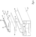
- the Figures 1 and 2 show an electric heater 10, which is intended to be used as a radiator in a building for heating a room. For this purpose, it can be attached with its rear side R to a building wall, not shown here. It comprises three main components, which are formed by a base body 20, an electrical heating resistor 40 and a clamping body 60. In the fully assembled state, the electrical heating resistor 40 is exclusively non-positively attached to the base body 20 by being pressed firmly against the base body by the clamping body 60 ( Figure 2 ).
- the base body 20 here consists of an extruded aluminum profile, the substantially rectangular cross section of which in Figure 2 is shown by way of example.
- it includes a contact surface 22 for the heating resistor 40, which is offset from the rear side R in the direction of the front side V into the aluminum profile.
- the base body 20 With respect to an inner central web 24 running perpendicular to the front side V, the base body 20 is designed to be axially symmetrical, the contact surface 22 also being located centrally or axially symmetrically to the central web 24.
- the contact surface 22 is thus in each case on both longitudinal sides of a protruding towards the rear side R.
- Profile area 26 surround. According to the present invention, the contact surface 22 has a profile that is slightly convex towards the rear side R.
- a first web 28 projects in the direction of the respective other profile area 26, which is continued on the inside by a longer web 30 which is angled by 90 ° and protrudes rearward behind the rear side R.
- the two webs 28 and 30 each form an L-shaped cross section on the mutually facing sides of the two profile areas 26.
- a second web 32 and, slightly above the contact surface 22 a third web 34 follow in the direction of the contact surface 22 offset inward. These webs 32 and 34 extend laterally, parallel to the rear side R in the direction of the respective other profile area 26.
- the second web 32 is narrower than the first web 28 and the third web 34 is narrower than the second web 32.
- the mutually facing webs 28 and 34 each form a first and a second projection, behind each of which a side edge of the clamping body 60 can be clamped in order to press the heating resistor 40 against the contact surface 22.
- the clamping body 60 is formed by an elongated aluminum sheet which has good thermal conductivity. It comprises a flat pressure web 62 and a flat holding web 64 angled therefrom by 90 °, so that the clamping body 60 overall has an L-shaped cross section.
- the pressure web 62 is made wider than the holding web 64, wherein it can be bent in a slightly resilient manner in the transverse direction.
- the pressure web 62 forms a pressure surface that rests against the electrical heating resistor 40 in the fully assembled state.
- the holding web 64 contains a plurality of transverse slots 66 which are oriented transversely to the longitudinal extension of the sheet metal profile and which divide the holding web 64 into a plurality of holding prongs 68.
- the free end edges on the one hand of the pressure web 62 and on the other hand of the holding web 64 or the holding prongs 68 each engage behind a projection formed by a web 28 and 34 in the fully assembled state.
- the holding web 64 Due to the subdivision of the holding web 64 into the plurality of holding prongs 68, these can be particularly easily pressed one after the other behind the projection formed by a web 28 after the free end edge 70 of the pressure web 62 has previously been placed on the opposite side under the web 34.
- the pressure web 62 is arched according to the convex surface of the contact surface 22 and thereby builds up the clamping force required to hold the heating resistor 40 in a non-positive manner.
- the arching of the pressure web 62 caused in this way causes the holding prongs 68 protruding at right angles from the area of the pressure web 62 protruding laterally over the contact surface 22 behind the projection formed by the web 28, where they are pressed with a central area against the rib 32 of the base body Hit 20. Since the free end edge of the pressure web 62 on the opposite side of the contact surface 22 at the same time rest against a profile wall of the base body 20 lying below the rib 34, an unintentional lateral displacement of the clamping body 60 cannot occur, so that the clamping body 60 and thus also the electrical heating resistor 40 is securely fixed to the base body 20.
- the electrical heating resistor 40 designed here as a self-regulating dynamic PTC heating element, is designed in the form of a flat strip, the length of which corresponds at least essentially to the length of the base body 20 and the clamping body 60. It is surrounded on both sides by a plastic casing which, like the electrical heating resistor 40 itself, consists of an elastic, slightly mechanically flexible material. On In this way, the electrical heating resistor 40 with the plastic cover can be flexibly deformed and easily adapt over the entire surface to the curvature given by the convex contact surface 22.
- the holding prongs 68 hold themselves well behind the projection formed by the web 28.
Abstract
Die Erfindung betrifft einen elektrischen Heizkörper (10) für die Beheizung von Räumen, umfassend einen Basiskörper (20) und einen kraftschlüssig daran gehaltenen elektrischen Heizwiderstand (40), der durch mindestens einen Klemmkörper (60) gegen den Basiskörper (20) gedrückt ist, wobei der Basiskörper (20) und/oder der Klemmkörper (60) eine konvex gewölbte Anlagefläche (22) aufweist, die gegen den elektrischen Heizwiderstand (40) angedrückt ist.The invention relates to an electric heater (10) for heating rooms, comprising a base body (20) and an electric heating resistor (40) held thereon in a force-locking manner, which is pressed against the base body (20) by at least one clamping body (60), wherein the base body (20) and / or the clamping body (60) has a convexly curved contact surface (22) which is pressed against the electrical heating resistor (40).
Description
Die vorliegende Erfindung betrifft einen elektrischen Heizkörper nach dem Oberbegriff von Anspruch 1. Der Heizkörper dient zum Beheizen von Räumen oder Teilen von Räumen in einem Gebäude und kann insbesondere als Designheizkörper oder als Radiator ausgebildet sein.The present invention relates to an electric radiator according to the preamble of claim 1. The radiator is used to heat rooms or parts of rooms in a building and can in particular be designed as a designer radiator or a radiator.
Derartige Heizkörper sind allgemein bekannt. Sie können als rein elektrisch betriebene Heizkörper, denen ausschließlich elektrische Energie zugeführt und mittels eines elektrischen Heizwiderstands in Wärme umgewandelt wird, oder als kombinierte Heizkörper, die einerseits an eine Zentralheizungsanlage angeschlossen sind und von einem durch diese erwärmten Heizmedium durchströmt werden, sowie andererseits noch ein zusätzliches elektrisches Heizelement zum Umwandeln elektrischer Energie in Wärme aufweisen, ausgeführt sein. Bei kombinierten Heizkörpern wird das elektrische Heizelement üblicherweise als Zusatzheizung für den Heizkörper verwendet, welches insbesondere in der Übergangszeit von Frühling oder Herbst eine elektrische Beheizung ermöglicht, wenn die Zentralheizungsanlage schon oder noch ausgeschaltet ist.Such radiators are generally known. They can be used as purely electrically operated radiators, to which only electrical energy is supplied and converted into heat by means of an electrical heating resistor, or as combined radiators, which are connected to a central heating system on the one hand and are flowed through by a heating medium heated by this, and an additional one on the other have an electrical heating element for converting electrical energy into heat. In the case of combined radiators, the electrical heating element is usually used as additional heating for the radiator, which enables electrical heating, especially in the transition period from spring to autumn, when the central heating system is already or is still switched off.
Ein kombinierter Heizkörper mit Vorlauf- und Rücklaufanschlüssen für ein zirkulierendes Heizmedium, bei dem in einem Verteilerrohr oder Sammelrohr des Heizkörpers ein elektrischer Heizstab angeordnet ist, ist beispielsweise aus der
Aus der
Aus der
Auch aus der
Eine durch Kleben ausgeführte Anbringung kann bei höheren Temperaturen oder bei bestimmten Oberflächen, etwa bei lackierten Basiskörpern problematisch sein. Insbesondere kann die Haltekraft der Klebverbindung mit der Zeit nachlassen. Auch geht eine Trennung des elektrischen Heizwiderstands vom Basiskörper, etwa bei einer Reparatur oder am Lebensende des Heizkörpers, bei einer Klebverbindung mit einem erheblichen Arbeitsaufwand einher.An attachment carried out by gluing can be problematic at higher temperatures or on certain surfaces, for example with painted base bodies. In particular, the holding force of the adhesive connection can decrease over time. Separation of the electrical heating resistor from the base body, for example during a repair or at the end of the life of the radiator, in the case of an adhesive connection, is associated with a considerable amount of work.
Diese Probleme treten bei einer kraftschlüssigen Befestigung des elektrischen Heizwiderstands nicht auf. Die Anbringung des elektrischen Heizwiderstands am Basiskörper über Klemmkörper erlaubt eine lange Haltbarkeit sowie eine besonders einfache Montage und Demontage.These problems do not arise when the electrical heating resistor is fastened in a non-positive manner. The attachment of the electrical heating resistor to the base body via clamping bodies allows a long service life and particularly simple assembly and disassembly.
Aufgabe der vorliegenden Erfindung ist es daher, einen elektrischen Heizkörper mit einer verbesserten kraftschlüssigen Anbringung des elektrischen Heizwiderstands am Basiskörper bereitzustellen.The object of the present invention is therefore to provide an electrical heating element with an improved force-locking attachment of the electrical heating resistor to the base body.
Diese Aufgabe wird erfindungsgemäß durch einen elektrischen Heizkörper nach Anspruch 1 gelöst. Vorteilhafte Ausgestaltungen und zweckmäßige Weiterbildungen der Erfindung ergeben sich aus den abhängigen Ansprüchen, der Beschreibung oder den Figuren.This object is achieved according to the invention by an electric heater according to claim 1. Advantageous refinements and expedient developments of the invention result from the dependent claims, the description or the figures.
Bei einem elektrischen Heizkörper für die Beheizung von Räumen, bei dem mindestens ein Klemmkörper einen elektrischen Heizwiderstand kraftschlüssig gegen einen Basiskörper andrückt, ist erfindungsgemäß vorgesehen, dass der Basiskörper eine konvex gewölbte Anlagefläche aufweist, gegen die der elektrische Heizwiderstand von dem Klemmkörper gedrückt wird, und/oder dass der Klemmkörper eine konvex gewölbte Anlagefläche aufweist, die gegen den elektrischen Heizwiderstand angedrückt ist.In the case of an electrical heating element for heating rooms, in which at least one clamping element presses an electrical heating resistor frictionally against a base element, it is provided according to the invention that the base element has a convexly curved contact surface against which the electrical heating resistance is pressed by the clamping element, and / or that the clamping body has a convexly curved contact surface which is pressed against the electrical heating resistor.
Mit anderen Worten ausgedrückt bedeutet das, dass der elektrische Heizwiderstand in Anlage an mindestens einer konvexen Kontaktfläche des Basiskörpers und/oder des Klemmkörpers ist.In other words, this means that the electrical heating resistor is in contact with at least one convex contact surface of the base body and / or of the clamping body.
Ein wesentlicher Vorteil liegt bei der erfindungsgemäßen Ausführung darin, dass der elektrische Heizwiderstand, der lediglich einen Teilbereich der Oberfläche des Basiskörpers bedeckt und daher eine sehr hohe Heizleistungsdichte aufweist, optimal an der Anlagefläche des Basiskörpers anliegt und vorteilhafterweise über seine gesamte Erstreckung sicher daran angedrückt gehalten wird.An essential advantage of the embodiment according to the invention is that the electrical heating resistor, which covers only a partial area of the surface of the base body and therefore has a very high heating power density, rests optimally on the contact surface of the base body and is advantageously held securely against it over its entire extent .
Ein weiterer wesentlicher Vorteil besteht darin, dass auch der Klemmkörper optimal an der von dem Basiskörper abgewandten Rückseite des elektrischen Heizwiderstands anliegt, so dass bei einem gut wärmeleitenden Material des Klemmkörpers Wärme auch von der Rückseite des elektrischen Heizwiderstands optimal abgeführt und vorteilhafterweise an den Basiskörper übertragen werden kann.Another essential advantage is that the clamping body also rests optimally on the rear side of the electrical heating resistor facing away from the base body, so that with a material that conducts heat well Clamping body heat can also be optimally dissipated from the back of the electrical heating resistor and advantageously transferred to the base body.
Vorteilhafterweise ist der elektrische Heizwiderstand ausschließlich nur durch den Klemmkörper an dem Basiskörper des Heizkörpers gehalten, so dass keine weiteren Befestigungsmittel erforderlich sind.The electrical heating resistor is advantageously held on the base body of the heating body only by the clamping body, so that no further fastening means are required.
Besonders vorteilhaft ist es, wenn der Klemmkörper seinerseits formschlüssig und kraftschlüssig an dem Basiskörper gehalten ist. Dadurch wird eine besonders einfache und schnell ausführbare Montage gewährleistet.It is particularly advantageous if the clamping body is held on the base body in a form-fitting and force-fitting manner. This ensures a particularly simple and quick assembly.
Gemäß einer besonders bevorzugten Ausführungsform wird vorgeschlagen, dass ein erster Bereich des Klemmkörpers einen ersten Vorsprung, den der Basiskörper aufweist, hintergreift. Vorzugsweise liegt der Klemmkörper dabei mit dem seitlich über die Anlagefläche hinausragenden ersten Bereich in einer zumindest annähernd senkrecht zu der Anlagefläche verlaufenden Richtung an dem ersten Vorsprung an. Auf diese Weise kann der Klemmkörper besonders einfach am Basiskörper gehalten werden.According to a particularly preferred embodiment, it is proposed that a first region of the clamping body engages behind a first projection which the base body has. In this case, the clamping body preferably rests against the first projection with the first region protruding laterally beyond the contact surface in a direction running at least approximately perpendicular to the contact surface. In this way, the clamping body can be held on the base body in a particularly simple manner.
Besonders vorteilhaft ist es dabei ferner, wenn außerdem ein zweiter Bereich des Klemmkörpers einen zweiten Vorsprung, den der Basiskörper zusätzlich aufweist, ebenfalls hintergreift. Vorzugsweise liegt der Klemmkörper auch dabei mit dem seitlich über die Anlagefläche hinausragenden zweiten Bereich in einer zumindest annähernd senkrecht zu der Anlagefläche verlaufenden Richtung an dem zweiten Vorsprung an. Vorteilhafterweise befindet sich der zweite Vorsprung des Klemmkörpers bezüglich der Anlagefläche für den elektrischen Heizwiderstand auf der dem ersten Vorsprung gegenüberliegenden Seite. Durch zwei von unterschiedlichen Bereichen des Klemmkörpers hintergriffene Vorsprünge des Basiskörpers kann unter elastischer Verformung des Klemmkörpers eine besonders einfach herzustellende und gleichzeitig besonders sichere kraftschlüssige Befestigung des Klemmkörpers am Basiskörper erreicht werden.It is also particularly advantageous if a second region of the clamping body also engages behind a second projection, which the base body also has. In this case, too, the clamping body preferably rests against the second projection with the second region protruding laterally beyond the contact surface in a direction running at least approximately perpendicular to the contact surface. The second projection of the clamping body is advantageously located on the side opposite the first projection with respect to the contact surface for the electrical heating resistor. By means of two projections of the base body which are engaged from behind by different areas of the clamping body, a particularly easy to manufacture and at the same time particularly secure non-positive fastening of the clamping body to the base body can be achieved with elastic deformation of the clamping body.
Vorzugsweise können der erste Vorsprung und/oder der zweite Vorsprung jeweils durch eine sich in Längsrichtung erstreckende Rippe des Basiskörpers gebildet sein, die seitlich in Richtung zur Anlagefläche vorsteht.Preferably, the first projection and / or the second projection can each be formed by a longitudinally extending rib of the base body which protrudes laterally in the direction of the contact surface.
Besonders günstig ist es dabei, wenn der Basiskörper einen dritten Vorsprung oder einen Anlagebereich aufweist, gegen den der Klemmkörper in einer zumindest annähernd parallel oder tangential zu der Anlagefläche verlaufenden Richtung anliegt, während er den ersten und den zweiten Vorsprung hintergreift. Hierdurch kann ein unbeabsichtigtes seitliches Verschieben des Klemmkörpers verhindert werden, so dass das Hintergreifen der beiden Vorsprünge und somit die kraftschlüssige Befestigung zuverlässig gesichert ist.It is particularly favorable when the base body has a third projection or a contact area against which the clamping body rests in a direction running at least approximately parallel or tangential to the contact surface while it engages behind the first and second projections. In this way, an unintentional lateral displacement of the clamping body can be prevented, so that the engagement of the two projections from behind and thus the non-positive fastening is reliably secured.
Besonders vorteilhaft ist es, wenn der Basiskörper mindestens eine mit einem Fluid gefüllte Kammer und/oder mindestens einen von einem Heizfluid durchströmbaren Kanal, der mit einem Vorlaufanschluss und einem Rücklaufanschluss des Heizkörpers verbunden ist, aufweist.It is particularly advantageous if the base body has at least one chamber filled with a fluid and / or at least one channel through which a heating fluid can flow and which is connected to a flow connection and a return connection of the heater.
Nach einer weiteren besonders bevorzugten Ausführungsform ist vorgesehen, dass der Basiskörper ein metallischer Profilkörper ist. In einem vorteilhafterweise längsgestreckten Profilkörper können Vorsprünge zur Anbringung des Klemmkörpers besonders einfach ausgeformt werden.According to a further particularly preferred embodiment, it is provided that the base body is a metallic profile body. In an advantageously elongated profile body, projections for attaching the clamping body can be formed in a particularly simple manner.
Vorzugsweise besteht der Basiskörper dabei aus einem extrudierten Aluminiumprofil, was sich bei geringem Gewicht durch eine gute Wärmeleitfähigkeit auszeichnet.The base body preferably consists of an extruded aluminum profile, which is characterized by good thermal conductivity and low weight.
Gemäß einer weiteren besonders bevorzugten Ausführungsform wird vorgeschlagen, dass der Klemmkörper durch ein Blech, insbesondere durch ein elastisches Aluminiumblech gebildet ist. Auf diese Weise kann der Klemmkörper gut die für die Aufbringung der Klemmkraft erforderlichen federnden Eigenschaften (Elastizität) aufweisen. Außerdem kann über ein gut wärmeleitendes Blech wie Aluminium besonders gut auch die an der Rückseite des elektrischen Heizwiderstands austretende Wärme aufgenommen und an den Basiskörper geleitet werden, so dass der elektrische Heizwiderstand durch den Klemmkörper quasi gekühlt wird.According to a further particularly preferred embodiment, it is proposed that the clamping body be formed by a sheet metal, in particular by an elastic aluminum sheet. In this way, the clamping body can well have the resilient properties (elasticity) required for applying the clamping force. In addition, the heat emerging from the rear of the electrical heating resistor can also be absorbed particularly well via a sheet of metal that conducts heat well, such as aluminum Base body are guided so that the electrical heating resistor is quasi cooled by the clamping body.
Vorzugsweise ist der Klemmkörper dabei durch einen längsgestreckten elastischen Blechstreifen oder ein längsgestrecktes elastisches Blechprofil gebildet.The clamping body is preferably formed by an elongated elastic sheet metal strip or an elongated elastic sheet metal profile.
Gemäß einer besonders bevorzugten Ausführungsform weist der Klemmkörper einen eine Andrückfläche ausbildenden Drucksteg und mindestens einen hiervon abgewinkelten Haltesteg auf. Der Drucksteg kann dabei die für das Andrücken des Heizwiderstands erforderliche Elastizität aufweisen und vorzugsweise konvex gewölbt ausgeführt sein. Auf diese Weise kann der Haltesteg, insbesondere eine freie Kante des Haltestegs einen ersten Bereich ausbilden, der einen ersten Vorsprung des Basiskörpers hintergreift, während der Drucksteg, insbesondere eine freie Kante des Druckstegs einen zweiten Bereich ausbildet, der einen zweiten Vorsprung des Basiskörpers hintergreift. Vorteilhafterweise kann der Haltesteg dabei gegen einen dritten Vorsprung oder einen Anlagebereich des Basiskörpers zur Anlage kommen, so dass der Klemmkörper gegen eine unbeabsichtigte seitliche Verlagerung gesichert und dadurch auch das Hintergreifen der beiden Vorsprünge des Basiskörpers durch den Haltesteg und den Drucksteg zuverlässig gewährleistet ist.According to a particularly preferred embodiment, the clamping body has a pressure web forming a pressure surface and at least one holding web angled therefrom. The pressure bar can have the elasticity required for pressing the heating resistor and preferably be convexly curved. In this way, the holding bar, in particular a free edge of the holding bar, can form a first area that engages behind a first projection of the base body, while the pressure bar, in particular a free edge of the pressure bar, forms a second area that engages behind a second projection of the base body. Advantageously, the holding web can come to rest against a third projection or an abutment area of the base body, so that the clamping body is secured against unintentional lateral displacement and the holding web and the pressure web reliably engage behind the two projections of the base body.
Besonders vorteilhaft ist es dabei für die Elastizität des die Andrückfläche ausbildenden Druckstegs, wenn die Höhe des mindestens einen Haltestegs geringer ist als die Breite des Druckstegs. Vorzugsweise ist der Haltesteg von dem Drucksteg in einem Winkel von 90° abgewinkelt.It is particularly advantageous for the elasticity of the pressure web forming the pressing surface if the height of the at least one holding web is less than the width of the pressure web. The holding web is preferably angled from the pressure web at an angle of 90 °.
Gemäß einer ersten bevorzugten Ausführungsform weist der Haltesteg mindestens einen Querschlitz auf, der den Haltesteg in mindestens zwei Halteklappen unterteilt. Dabei verläuft der Querschlitz vorteilhafterweise quer zur Längserstreckung des Blechprofils. Auf diese Weise können die Halteklappen des Haltestegs besonders leicht hinter einen Vorsprung des Basiskörpers gebracht werden.According to a first preferred embodiment, the holding web has at least one transverse slot which divides the holding web into at least two holding flaps. The transverse slot advantageously runs transversely to the longitudinal extension of the sheet metal profile. In this way, the retaining flaps of the retaining web can be brought particularly easily behind a projection of the base body.
Gemäß einer zweiten bevorzugten Ausführungsform weist der Haltesteg eine Vielzahl von Querschlitzen auf, die den Haltesteg in eine dementsprechende Vielzahl von Haltezinken unterteilen. Hierdurch können die einzelnen Haltezinken noch leichter hinter einen Vorsprung des Basiskörpers gebracht werden.According to a second preferred embodiment, the holding web has a plurality of transverse slots which subdivide the holding web into a corresponding plurality of holding prongs. As a result, the individual holding prongs can be brought even more easily behind a projection of the base body.
Vorzugsweise ist nur ein einziger Klemmkörper vorgesehen. Alternativ können aber auch zwei oder mehr Klemmkörper zum Andrücken des elektrischen Heizwiderstands gegen den Basiskörper angeordnet sein.Preferably, only a single clamping body is provided. Alternatively, however, two or more clamping bodies can also be arranged for pressing the electrical heating resistor against the base body.
Gemäß einer besonders bevorzugten Ausführungsform ist der Heizwiderstand in der Form eines flachen Streifens mit einer an den Basiskörper angedrückten Kontaktfläche ausgebildet.According to a particularly preferred embodiment, the heating resistor is designed in the form of a flat strip with a contact surface pressed against the base body.
Besonders vorteilhaft ist es dabei, wenn der elektrische Heizwiderstand flexibel ist, also aus einem elastischen, also leicht mechanisch verformbaren Material besteht. Dadurch wird beim Andrücken durch den Klemmkörper eine optimale und vollflächige Anlage des Heizwiderstands an der Anlagefläche des Basiskörpers ermöglicht.It is particularly advantageous if the electrical heating resistor is flexible, that is to say consists of an elastic, that is to say easily mechanically deformable material. This enables optimal and full-surface contact of the heating resistor on the contact surface of the base body when the clamping body is pressed against it.
Besonders vorteilhaft ist es ferner, wenn dass der Heizwiderstand von einem Kunststoffmantel umgeben ist. Insbesondere dann, wenn der Heizwiderstand leicht mechanisch verformbar ausgeführt ist, besteht auch die Umhüllung vorteilhafterweise aus einem elastischen, also leicht biegsamen bzw. verformbaren Kunststoff.It is also particularly advantageous if the heating resistor is surrounded by a plastic jacket. In particular, if the heating resistor is designed to be easily mechanically deformable, the sheath also advantageously consists of an elastic, that is to say easily flexible or deformable plastic.
Vorteilhafterweise ist der elektrische Heizwiderstand ein PTC-Heizelement. PTC- Heizelemente regeln als selbstregelnde dynamische Heizelemente bei Erreichen einer bestimmten Grenztemperatur durch Ansteigen ihres Widerstandes ihre Leistung selbstständig ab, weswegen sie besonders gut für Heizanwendungen verwendet werden können.The electrical heating resistor is advantageously a PTC heating element. As self-regulating dynamic heating elements, PTC heating elements regulate their power automatically when a certain limit temperature is reached by increasing their resistance, which is why they can be used particularly well for heating applications.
Weitere Vorteile und Merkmale der Erfindung ergeben sich aus der nachfolgenden Beschreibung zu den in den Zeichnungen dargestellten Ausführungsbeispielen.Further advantages and features of the invention emerge from the following description of the exemplary embodiments shown in the drawings.
Es zeigen:
- Figur 1:
- perspektivische Explosionsdarstellung der Bestandteile eines erfindungsgemäßen elektrischen Heizkörpers, und
- Figur 2:
- Querschnitt durch den Heizkörper aus
Figur 1 im fertig montiertem Zustand.
- Figure 1:
- perspective exploded view of the components of an electric heater according to the invention, and
- Figure 2:
- Cross-section through the radiator
Figure 1 in the fully assembled state.
Die
Der Basiskörper 20 besteht hier aus einem stranggepressten Aluminiumprofil, dessen im wesentlichen rechteckiger Querschnitt in
An der Rückseite R der beiden Profilbereiche 26 steht jeweils ein erster Steg 28 in Richtung des jeweils anderen Profilbereichs 26 vor, der innen durch einen um 90° abgewinkelten und hinter der Rückseite R nach hinten abstehenden längeren Steg 30 fortgesetzt ist. Insgesamt bilden die beiden Stege 28 und 30 dabei an den einander zugewandten Seiten der beiden Profilbereiche 26 jeweils einen L-förmigen Querschnitt aus.On the rear side R of the two
Ausgehend von den in der Rückseite R des Basiskörpers 20 verlaufenden ersten Stegen 28 folgen in Richtung zur Anlagefläche 22 hin nach innen versetzt auf beiden Seiten jeweils zunächst ein zweiter Steg 32 und geringfügig oberhalb der Anlagefläche 22 noch ein dritter Steg 34. Auch diese Stege 32 und 34 erstrecken sich seitlich, parallel zur Rückseite R in Richtung zu dem jeweils anderen Profilbereich 26. Dabei ist der zweite Steg 32 schmaler als der erste Steg 28 und der dritte Steg 34 schmaler als der zweite Steg 32 ausgeführt.Starting from the
Die einander zugewandten Stege 28 und 34 bilden jeweils einen ersten und zweiten Vorsprung aus, hinter denen jeweils eine Seitenkante des Klemmkörpers 60 festgeklemmt werden kann, um den Heizwiderstand 40 gegen die Anlagefläche 22 anzudrücken.The mutually facing
Der Klemmkörper 60 ist durch ein langgestrecktes Aluminiumblech gebildet, das eine gute Wärmeleitfähigkeit aufweist. Er umfasst einen flachen Drucksteg 62 und einen hiervon um 90° abgewinkelten flachen Haltesteg 64, so dass der Klemmkörper 60 insgesamt einen L-förmigen Querschnitt hat. Der Drucksteg 62 ist breiter ausgeführt als der Haltesteg 64, wobei er in Querrichtung leicht federelastisch biegbar ist. Der Drucksteg 62 bildet eine Andrückfläche, die im fertig montierten Zustand an dem elektrischen Heizwiderstand 40 anliegt.The clamping
Der Haltesteg 64 enthält eine Vielzahl von Querschlitzen 66, die quer zur Längserstreckung des Blechprofils orientiert sind und den Haltesteg 64 in eine Vielzahl von Haltezinken 68 unterteilen. Die freien Endkanten einerseits des Druckstegs 62 und andererseits des Haltestegs 64 bzw. der Haltezinken 68 hintergreifen im fertig montierten Zustand jeweils einen durch einen Steg 28 und 34 gebildeten Vorsprung.The holding
Aufgrund der Unterteilung des Haltestegs 64 in die Vielzahl von Haltezinken 68 können diese nacheinander besonders leicht hinter den durch einen Steg 28 gebildeten Vorsprung gedrückt werden, nachdem zuvor die freie Endkante 70 des Druckstegs 62 auf der gegenüberliegenden Seite unter den Steg 34 platziert wurde. Beim Eindrücken der Haltezinken 68 hinter den durch den Steg 28 gebildeten Vorsprung wird der Druckstegs 62 entsprechend der konvexen Oberfläche der der Anlagefläche 22 gewölbt und baut dadurch die zum kraftschlüssigen Halten des Heizwiderstands 40 erforderliche Klemmkraft auf. Gleichzeitig bewirkt die so hervorgerufene Wölbung des Druckstegs 62, dass die von dem die Anlagefläche 22 seitlich überragenden Bereich des Druckstegs 62 rechtwinklig abstehenden Haltezinken 68 hinter den durch den Steg 28 gebildeten Vorsprung gedrückt werden, wo sie mit einem mittleren Bereich gegen die Rippe 32 des Basiskörpers 20 anschlagen. Da die freie Endkante des Druckstegs 62 auf der gegenüberliegenden Seite der Anlagefläche 22 gleichzeitig an einem unterhalb der Rippe 34 liegenden Profilwand des Basiskörpers 20 anliegen, kann eine unbeabsichtigte seitliche Verlagerung des Klemmkörpers 60 nicht erfolgen, so dass der Klemmkörper 60 und somit auch der elektrische Heizwiderstand 40 sicher an dem Basiskörpers 20 fixiert ist.Due to the subdivision of the holding
Der hier als selbstregelndes dynamisches PTC-Heizelement ausgeführte elektrische Heizwiderstand 40 ist in der Form eines flachen Streifens ausgebildet, dessen Länge zumindest im Wesentlichen der Länge des Basiskörpers 20 und des Klemmkörpers 60 entspricht. Er ist beidseitig von einer Kunststoffumhüllung umgeben, die ebenso wie der elektrische Heizwiderstand 40 selber aus einem elastischen, leicht mechanisch biegsamen Material besteht. Auf diese Weise kann sich der elektrische Heizwiderstand 40 mit der Kunststoffumhüllung flexibel verformen und leicht der durch die konvexe Anlagefläche 22 vorgegebenen Wölbung vollflächig anpassen.The
Die Montage des elektrischen Heizkörper 10 läuft folgendermaßen ab:
- Zuerst wird der elektrische Heizwiderstand 40 auf die konvexe Anlagefläche 22 des
Basiskörpers 20 aufgelegt, - dann wird der Klemmkörper 60 angebracht, indem zunächst die freie Endkante 70 des
Druckstegs 62 unter einenSteg 34 desBasiskörpers 20 gesteckt wird, - nach dem Einstecken der Endkante 70 wird der Drucksteg 62 in Querrichtung über den auf der konvexen Anlagefläche 22 liegenden Heizwiderstand 40 gebogen und durch Einrasten der einzelnen Haltezinken 68 auf der gegenüberliegenden Seite hinter
den Steg 28 fixiert.
- First, the
electrical heating resistor 40 is placed on theconvex contact surface 22 of thebase body 20, - then the clamping
body 60 is attached by first inserting thefree end edge 70 of thepressure web 62 under aweb 34 of thebase body 20, - After inserting the
end edge 70, thepressure web 62 is bent in the transverse direction over theheating resistor 40 lying on theconvex contact surface 22 and is fixed behind theweb 28 on the opposite side by engaging the individual retaining prongs 68.
Aufgrund der bei der Wölbung des Druckstegs 62 zur Anpassung an die konvexe Anlagefläche 22 erzeugten elastischen Spannung des im Querschnitt L-förmigen Klemmkörpers 60 halten die Haltezinken 68 gut von selbst hinter dem durch den Steg 28 gebildeten Vorsprung.Due to the elastic tension of the clamping
Im Ergebnis wird so eine perfekte, dauerhaft stabile Klemmung des Heizwiderstands 40 an dem Basiskörper 20 des elektrischen Heizkörpers 10 erzielt. Dabei werden weder stoffschlüssige Verbindungsmittel noch Schrauben benötigt. Außerdem wird die an der von der Anlagefläche 22 abgewandten Rückseite des Heizwiderstands 40 abgegebene Wärme über den aus Aluminium bestehenden Klemmkörper 60 an den Basiskörper 20 geleitet und steht somit ebenfalls zur gewünschten Beheizung des Raumes zur Verfügung.As a result, perfect, permanently stable clamping of the
Claims (15)
dadurch gekennzeichnet,
dass der Basiskörper (20) und/oder der Klemmkörper (60) eine konvex gewölbte Anlagefläche (22) aufweist, die gegen den elektrischen Heizwiderstand (40) angedrückt ist.Electric heating element (10) for heating rooms, comprising a base body (20) and an electric heating resistor (40) held thereon in a force-locking manner and which is pressed against the base body (20) by at least one clamping body (60),
characterized,
that the base body (20) and / or the clamping body (60) has a convexly curved contact surface (22) which is pressed against the electrical heating resistor (40).
Applications Claiming Priority (1)
| Application Number | Priority Date | Filing Date | Title |
|---|---|---|---|
| DE102019110622.2A DE102019110622A1 (en) | 2019-04-24 | 2019-04-24 | Electric radiator |
Publications (1)
| Publication Number | Publication Date |
|---|---|
| EP3734164A1 true EP3734164A1 (en) | 2020-11-04 |
Family
ID=70390940
Family Applications (1)
| Application Number | Title | Priority Date | Filing Date |
|---|---|---|---|
| EP20170742.9A Pending EP3734164A1 (en) | 2019-04-24 | 2020-04-21 | Electric radiator |
Country Status (2)
| Country | Link |
|---|---|
| EP (1) | EP3734164A1 (en) |
| DE (1) | DE102019110622A1 (en) |
Cited By (1)
| Publication number | Priority date | Publication date | Assignee | Title |
|---|---|---|---|---|
| US11892175B2 (en) | 2017-11-16 | 2024-02-06 | Lancey Energy Storage | Heating appliance with a built-in battery arranged in the incoming fresh air flow |
Citations (7)
| Publication number | Priority date | Publication date | Assignee | Title |
|---|---|---|---|---|
| DE2738036A1 (en) * | 1976-08-23 | 1978-03-02 | Roland Keller | HEATING ELEMENT FOR ROOM HEATING |
| DE29918763U1 (en) | 1998-10-27 | 2000-01-27 | Vaillant Joh Gmbh & Co | Radiator with an essentially meandering water flow |
| EP1584873A1 (en) | 2004-04-05 | 2005-10-12 | Zehnder Verkaufs- und Verwaltungs AG | Heating system |
| DE202006007968U1 (en) | 2006-05-11 | 2006-07-27 | Kermi Gmbh | Heater of tubes and distribution tubes with an electrical heating rod, e.g. a bathroom towel rail, has a recirculating mini pump to distribute the heating medium |
| DE102005002840A1 (en) | 2005-01-20 | 2006-08-03 | The Heating Company Bvba | Heater has at least a secondary electrically isolating insulating means which are effective between heater and electrically heating element, which is completely surrounded by one or both insulating means |
| DE102008043893A1 (en) * | 2007-11-26 | 2009-05-28 | Denso Corp., Kariya-shi | Electrical heating device has air gap, in which pair of pressure spring is arranged, where pressure springs are provided between upper and lower end of heating pile body, and between upper and lower frame |
| EP2251612A1 (en) * | 2009-05-04 | 2010-11-17 | Atlantic Industrie | Electric radiator with heat-transfer fluid made up of moulded modular elements |
Family Cites Families (3)
| Publication number | Priority date | Publication date | Assignee | Title |
|---|---|---|---|---|
| DE2062442A1 (en) * | 1970-12-18 | 1972-06-29 | Turk & Hillinger KG, 7200 Tuttlingen | Electrically heated cladding for heaters or the like |
| DE3108928C2 (en) * | 1981-03-10 | 1984-08-09 | Valentino-Valerio 5760 Arnsberg Giacosa | Radiators for central heating |
| FR2947614A1 (en) * | 2009-07-02 | 2011-01-07 | Alain Galmes | Heat exchanger element for heating e.g. office, has parts formed from extruded aluminum profiles and forming convector radiator with battery, and heat accumulator filled with refractory materials to retain heat emitted by resistance plate |
-
2019
- 2019-04-24 DE DE102019110622.2A patent/DE102019110622A1/en active Pending
-
2020
- 2020-04-21 EP EP20170742.9A patent/EP3734164A1/en active Pending
Patent Citations (7)
| Publication number | Priority date | Publication date | Assignee | Title |
|---|---|---|---|---|
| DE2738036A1 (en) * | 1976-08-23 | 1978-03-02 | Roland Keller | HEATING ELEMENT FOR ROOM HEATING |
| DE29918763U1 (en) | 1998-10-27 | 2000-01-27 | Vaillant Joh Gmbh & Co | Radiator with an essentially meandering water flow |
| EP1584873A1 (en) | 2004-04-05 | 2005-10-12 | Zehnder Verkaufs- und Verwaltungs AG | Heating system |
| DE102005002840A1 (en) | 2005-01-20 | 2006-08-03 | The Heating Company Bvba | Heater has at least a secondary electrically isolating insulating means which are effective between heater and electrically heating element, which is completely surrounded by one or both insulating means |
| DE202006007968U1 (en) | 2006-05-11 | 2006-07-27 | Kermi Gmbh | Heater of tubes and distribution tubes with an electrical heating rod, e.g. a bathroom towel rail, has a recirculating mini pump to distribute the heating medium |
| DE102008043893A1 (en) * | 2007-11-26 | 2009-05-28 | Denso Corp., Kariya-shi | Electrical heating device has air gap, in which pair of pressure spring is arranged, where pressure springs are provided between upper and lower end of heating pile body, and between upper and lower frame |
| EP2251612A1 (en) * | 2009-05-04 | 2010-11-17 | Atlantic Industrie | Electric radiator with heat-transfer fluid made up of moulded modular elements |
Cited By (1)
| Publication number | Priority date | Publication date | Assignee | Title |
|---|---|---|---|---|
| US11892175B2 (en) | 2017-11-16 | 2024-02-06 | Lancey Energy Storage | Heating appliance with a built-in battery arranged in the incoming fresh air flow |
Also Published As
| Publication number | Publication date |
|---|---|
| DE102019110622A1 (en) | 2020-10-29 |
Similar Documents
| Publication | Publication Date | Title |
|---|---|---|
| EP1931176B1 (en) | An electrical heating device and its method of manufacturing | |
| EP1327834B1 (en) | Radiating element for a heating apparatus | |
| DE102006055216B4 (en) | Heating device for diesel fuel and heated diesel filter system | |
| EP1847786B1 (en) | Heating device | |
| DE112016000688B4 (en) | Electric heater | |
| EP2298582A1 (en) | Electric heating device and method for its production | |
| EP0379874A1 (en) | Securing part for PTC elements | |
| DE19848169A1 (en) | Heating driver's cabin of commercial vehicles rapidly | |
| DE102006018151B4 (en) | heater | |
| EP3734164A1 (en) | Electric radiator | |
| EP2012390B1 (en) | Ground clamp for potential equalisation of cable conduits | |
| DE102019101451A1 (en) | Profile arrangement | |
| EP3378279B1 (en) | Radiator means for an electrical heater and electrical heater | |
| EP2266823A1 (en) | Electric heating device | |
| EP3856568A1 (en) | Extensible connector for a contact line, and contact line | |
| EP2754803B1 (en) | Espagnolette fitting for a window or door and driving rod for such an espagnolette fitting | |
| EP2754805B1 (en) | Locking bar for an espagnolette fitting | |
| EP2273638A2 (en) | Clip for cable channels for laminating cut edges | |
| DE202014000509U1 (en) | Wall plate for a dryer system | |
| EP3303062B1 (en) | Arrangement for fixing a strip-shaped attachement | |
| DE102016116882A1 (en) | Assembly unit with a mounting part and a sleeve fixed therein | |
| AT523027A1 (en) | Fastening for a thermal insulation layer in a rail vehicle in integral construction. | |
| DE202013102640U1 (en) | ceiling element | |
| EP2157270B1 (en) | Heat isolating profile for flame retardant constructions and composite profile for doors, windows and facades | |
| DE102008050481A1 (en) | Vehicle heating system, vehicle air conditioning system with heating device and method for mounting a heating device |
Legal Events
| Date | Code | Title | Description |
|---|---|---|---|
| PUAI | Public reference made under article 153(3) epc to a published international application that has entered the european phase |
Free format text: ORIGINAL CODE: 0009012 |
|
| STAA | Information on the status of an ep patent application or granted ep patent |
Free format text: STATUS: THE APPLICATION HAS BEEN PUBLISHED |
|
| AK | Designated contracting states |
Kind code of ref document: A1 Designated state(s): AL AT BE BG CH CY CZ DE DK EE ES FI FR GB GR HR HU IE IS IT LI LT LU LV MC MK MT NL NO PL PT RO RS SE SI SK SM TR |
|
| AX | Request for extension of the european patent |
Extension state: BA ME |
|
| STAA | Information on the status of an ep patent application or granted ep patent |
Free format text: STATUS: REQUEST FOR EXAMINATION WAS MADE |
|
| 17P | Request for examination filed |
Effective date: 20210504 |
|
| RBV | Designated contracting states (corrected) |
Designated state(s): AL AT BE BG CH CY CZ DE DK EE ES FI FR GB GR HR HU IE IS IT LI LT LU LV MC MK MT NL NO PL PT RO RS SE SI SK SM TR |
|
| STAA | Information on the status of an ep patent application or granted ep patent |
Free format text: STATUS: EXAMINATION IS IN PROGRESS |
|
| 17Q | First examination report despatched |
Effective date: 20221011 |