EP3734158B1 - Verfahren zur Reduzierung von Stickoxiden und Kohlenmonoxid in Feuerkammern von Wasser- und Dampfkesseln, insbesondere Rostkesseln. - Google Patents
Verfahren zur Reduzierung von Stickoxiden und Kohlenmonoxid in Feuerkammern von Wasser- und Dampfkesseln, insbesondere Rostkesseln. Download PDFInfo
- Publication number
- EP3734158B1 EP3734158B1 EP20020236.4A EP20020236A EP3734158B1 EP 3734158 B1 EP3734158 B1 EP 3734158B1 EP 20020236 A EP20020236 A EP 20020236A EP 3734158 B1 EP3734158 B1 EP 3734158B1
- Authority
- EP
- European Patent Office
- Prior art keywords
- furnace chamber
- process gas
- injection
- reagent
- injected
- Prior art date
- Legal status (The legal status is an assumption and is not a legal conclusion. Google has not performed a legal analysis and makes no representation as to the accuracy of the status listed.)
- Active
Links
Images

Classifications
-
- F—MECHANICAL ENGINEERING; LIGHTING; HEATING; WEAPONS; BLASTING
- F23—COMBUSTION APPARATUS; COMBUSTION PROCESSES
- F23J—REMOVAL OR TREATMENT OF COMBUSTION PRODUCTS OR COMBUSTION RESIDUES; FLUES
- F23J7/00—Arrangement of devices for supplying chemicals to fire
-
- F—MECHANICAL ENGINEERING; LIGHTING; HEATING; WEAPONS; BLASTING
- F23—COMBUSTION APPARATUS; COMBUSTION PROCESSES
- F23C—METHODS OR APPARATUS FOR COMBUSTION USING FLUID FUEL OR SOLID FUEL SUSPENDED IN A CARRIER GAS OR AIR
- F23C9/00—Combustion apparatus characterised by arrangements for returning combustion products or flue gases to the combustion chamber
-
- F—MECHANICAL ENGINEERING; LIGHTING; HEATING; WEAPONS; BLASTING
- F23—COMBUSTION APPARATUS; COMBUSTION PROCESSES
- F23C—METHODS OR APPARATUS FOR COMBUSTION USING FLUID FUEL OR SOLID FUEL SUSPENDED IN A CARRIER GAS OR AIR
- F23C2202/00—Fluegas recirculation
Definitions
- the object of the invention is a method for the reduction of nitrogen oxides and carbon monoxide in the furnace chambers of water and steam boilers, especially grate boilers and a system for the reduction of nitrogen oxides and carbon monoxide in the furnace chambers of water and steam boilers, especially grate boilers, used to reduce the formation of nitrogen oxides and carbon monoxide and/or their reduction in the furnace chambers of heating boilers and power boilers, especially grate boilers, and a system for the application of this method.
- the method described in the patent application P.423576 assumes that the process gas, or process gas and reagent, are injected into the furnace chamber in the opposite direction to the main natural direction of the flue gas flow through the chamber, preferably from top to bottom, i.e. in the case of injection from the top, side or front wall of the firebox, in the direction of temperature rise in the furnace chamber, and in the case of process gas injection through lances from the back wall of the firebox, as an additional reinforcement of the swirl, the process gas is supplied horizontally, with a jet deviation of +/-45°, in a plane parallel to the longitudinal symmetry plane of the furnace chamber.
- the process gas injection points are located on the front, top, side or rear wall of the furnace chamber, while the reagent and process gas injection points are located on the front, side or top wall of the furnace chamber, while the process gas injection points are located at a distance of up to 0.5 depth of the furnace chamber from the pipe axis of the front wall while when process gas is injected from the rear wall of the furnace chamber, the injection points are located at a distance of up to 0.2 depth of the furnace chamber from the pipe axis of the rear wall of the chamber.
- the above described method of feeding process gas or process gas and reagent causes a flue gas stream of high NOx concentration at the rear wall of the furnace chamber, on a significant part of the boiler width, and the described method of feeding process gas and reagent through lances mounted on the side walls of the boiler furnace chamber makes it possible for the reagent to enter this stream and reduce NOx compounds in this area.
- the technical problem to be solved is how to eliminate the abovementioned drawbacks and limitations, while guaranteeing further reduction of NOx emissions, reduction of CO emissions, minimising or completely eliminating the reagent in flue gases and fly ashes, increasing the efficiency of the system and lowering operating costs.
- the essence of the invention which is a method for the reduction of nitrogen oxides and carbon monoxide in the furnace chambers of water and steam boilers, especially grate boilers consists in that process gas, being air, flue gas or combustion air mixture, in its full range, i.e.
- process gas is supplied to the furnace chamber at a speed of 30 to 180 m/s, preferably 135 m/s, in the amount of up to 20% of stoichiometric air demand necessary to burn the fuel supplied to the boiler, preferably 15%, with up to 60% of the process gas being injected via lances built into the front wall of the furnace chamber, with up to 60% of the process gas being injected through lances installed on the rear wall of the furnace chamber, up to 25% of the process gas is injected through lances installed on the upper wall of the furnace chamber and up to 15% of the process gas is injected through lances installed on the side walls of the furnace chamber; moreover, the reagent is delivered to the furnace chamber at a rate of 30 to 180 m/s, preferably 135
- temperature and the share of O 2 , CO or NOx in the flue gas such parameters being monitored by measuring devices mounted inside the furnace chamber in the form of temperature sensors and/or devices mounted outside the furnace chamber being the flue gas analyser, and the regulation is carried out by means of actuators individually for each injection point or group of injection points mounted on a given wall of the furnace chamber, on a given level or with a specific injection direction.
- the dynamic effect of the process gas stream was used to intensify the mixing process in the furnace chamber by inducing strong internal flue gas recirculation inside the furnace chamber and a strong swirl whose direction is opposite to the main, natural flue gas flow direction and the swirl plane is parallel to the longitudinal symmetry plane of the furnace chamber.
- the solution according to the method allows for precise control of the temperature in the furnace chamber in the area where nitrogen oxides are reduced and CO is burned, reducing the concentration of the reagent in the furnace chamber, which minimises the risk of corrosion of the equipment components; moreover, the invention according to one of the embodiments, increases the capacity of the system by placing the lances on several levels of the furnace chamber, especially in the case of a considerable variability of the boiler load and this is usually used in units with higher power output.
- the invention according to the method also reduces reagent consumption in relation to known methods and thus allows to minimize the content of unreacted reagent in fly ashes and flue gases, which plays a very important role in terms of system operating costs, environmental protection and ash management.
- the opposite direction of reagent injection in relation to the main, natural direction of flue gas flow and to the inside of the generated swirls, as well as the described points and directions of injection have a very important advantage in relation to the traditional directions and places of reagent injection cited in the state of the art investigation, because in the described method according to the invention, there is no such phenomenon (or if it occurs it is limited to a minimum) as entrainment of unreacted reagent particles, directly after it has been injected into the furnace chamber by the flue gases into the convection part of the boiler, i.e.
- the reduction reaction takes place in the temperature range from 850°C to 1050°C and in the presence of nitrogen compounds; further on, the unreacted particles of the reagent enter the temperature area above 1 050°C where they bind with oxygen and form NOx-type compounds, which then, together with the products of combustion, head up the furnace chamber in accordance with the main natural draught of the combustion chamber where they encounter the unreacted reagent and the temperature conditions required for the occurrence of the NOX reduction reaction; part of the still unreacted reagent and unreacted nitrogen compounds (NOX) are returned to an area convenient for the NOX reduction reaction, through strong swirls of recirculating flue gas produced by the process gas stream.
- NOX nitrogen compounds
- This natural and spontaneous course of the process contributes to the efficiency of the reduction process and to a large extent protects the system against the ingress of unreacted reagent into the ash, dust or flue gas treatment and discharge systems;
- another advantage of the method according to the invention is that the process gas is injected into the furnace chamber in the opposite direction to the natural direction of the flue gas movement in the furnace chamber and at a high rate turns back towards the grate i.e. into the high temperature area, particles of unburned coal, which in the hitherto known solutions are entrained from the layer of coal moving on the grate by the blast air supplied from the grate and, as coal, together with fly ashes enter the dust extraction systems significantly reducing their efficiency.
- the presented method according to the invention significantly reduces the content of the carbon element in fly ash, which directly contributes to the increase in the efficiency of the system and also reduces the amount of fly ash carried by the flue gases leaving the boiler and entering the dedusting systems, which extends the service life of the devices and in newly built units enables the use of smaller first-stage dedusting systems reducing the equipment cost. This effect is particularly noticeable when burning poorer quality coal containing a lot of coal fines.
- the presented method of feeding the process gas or process gas and reagent produces a strong, main, reverse internal recirculation swirl and, depending on the boiler capacity, one to two additional swirls, one called the upper swirl, which is formed in the area bounded by the front wall, the upper and the stream of process gas injected from the lances mounted on the rear wall of the furnace chamber, this swirl being particularly noticeable at medium and high boiler loads, and a second one, called the down swirl, which is formed in the area bounded by the rear wall, the grate deck and the flue gas stream moving from the front zones of the grate towards the rear wall and further on towards the festoon, this swirl being particularly noticeable at low boiler loads;
- the main swirl and the upper swirl generated at medium and high boiler loads suck in flue gases from the main flue gas stream, from the area just before the furnace chamber is connected to the convection line, and thus create optimal conditions for nitrogen oxide reduction and carbon monoxide afterburning, with minimal oxygen content in flue gas and minimum amount of reagent entering the chimney
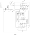
- Figure 1 shows the block diagram of the system for the realization of the method where: 4 - is the furnace chamber, 5 - is the front process gas/reagent collector, 6 - is the front process gas injection lance, 7 - is the front reagent injection lance/nozzle, 8 - is the convection part of the boiler, 9 - is the rear process gas collector, 10 - is the rear process gas injection lance, 11 - is the upper process gas/reagent collector, 12 - is the upper process gas injection lance, 13 - is the upper reagent injection lance, 15 - is the side process gas/reagent collector, 16 - is the side process gas injection lance, 17 - is the side reagent injection lance, 18 - is the process gas intake, 19 - is the control and shut-off component of the process gas feeder - air system, 20 - is the control and shut-off component of the process gas feeder - flue gas system, 21 - is the process gas fan, 22 - is the measuring system installed on the process gas collector, 23
- Figure 2 shows in a schematic and illustrative manner the place of installation of process gas and reagent injection lances, as well as the flow lines and swirl directions which occur during combustion in the furnace chamber of the equipment, preferably a grate boiler, where: 1 - is the sub-grate box of air, 2 - is the layer of fuel moving on the grate, 3 - is the grate, 4 - is the furnace chamber, 5 - is the front process gas/reagent collector, 6 - is the front process gas injection lance, 7 - is the front reagent injection lance/nozzle, 8 - is the convection part of the boiler, 9 - is the rear process gas collector, 10 - is the rear process gas injection lance, 11 - is the top process gas/reagent collector, 12 - is the top process gas injection lance, 13 - is the top injection lance of the reagent, 14 - is the temperature sensor, 15 - is the side collector of the process gas/reagent, 16 - is the side injection lance
- FIG. 2 The example embodiment according to the method will be illustrated by Fig. 2 in which A is the primary air pumped by the blast air fan to the control valves and then to the sub-grate boxes 1, whose task is to dose the oxidant in a controlled way to fuel 2 moving on the grate 3.
- A is the primary air pumped by the blast air fan to the control valves and then to the sub-grate boxes 1, whose task is to dose the oxidant in a controlled way to fuel 2 moving on the grate 3.
- fuel is burned and the amount of oxidant supplied in the form of primary air A ranges from 0.7 to 1.3 of the amount of stoichiometric air needed for full and complete combustion of fuel 2, preferably less than 1.0, moving on grate 3 as defined by the standards for this type of equipment.
- process gas (PG) or process gas and reagent (PG+R) are injected through collector 5 mounted outside the chamber, up to 60% of the process gas supplied to the system, through a series of lances 6 and 7 made and installed in such a way that the direction of injection of process gas (PG) or process gas with reagent (PG+R ) is opposite to the main direction of flow through the furnace chamber 4 with a jet deviation of +/-15° in the plane parallel to the longitudinal symmetry plane of the furnace chamber, whereby part of the process gas (PG) or process gas with reagent (PG+R ) accounting for up to 20% of the total amount of the process gas or process gas and reagent fed through
- process gas (PG) accounting for up to 60% of the process gas supplied to the system through collector 9 built in the convection part of boiler 8 and through lances 10 mounted on the rear wall of the furnace chamber 4, at the level of the lower edge of the boiler festoon is injected in the direction of grate 3 at an angle of 45°, and this angle is measured between the centre line of the jet and the back wall of the furnace chamber and another portion of process gas (PG) or process gas and reagent (PG+R) accounting for up to 25% of the process gas supplied to the system, via collector 11 mounted outside the boiler furnace chamber and through lances 12 and 13 mounted on the upper wall of the boiler furnace chamber 4 is injected in the opposite direction to the main direction of the FG flow through furnace chamber 4, whereby injection from each of lances 12 and/or 13 is made from at least one point, with a jet deviation of up to +/- 60° in the plane parallel to the longitudinal symmetry plane of the furnace chamber; the remaining process gas (PG) or process gas and
- the injection rate of process gas (PG) or reagent (R) is from 30 to 180 m/s, preferably 135 m/s, and the process gas stream accounts for up to 20% of the air stream necessary for full and complete combustion of the fuel as defined by the standards for this type of equipment; due to high speed, significant mass of the process gas stream and the way it is fed into the furnace chamber, a strong internal recirculation of iFGR flue gas inside furnace chamber 4 and a strong main swirl (MS) are produced, and depending on the boiler capacity, one or two additional swirls, one called upper swirl (US) and the other called down swirl (DS); the swirls rotate in a plane parallel to the longitudinal symmetry plane of the furnace chamber.
- PG process gas
- R reagent
- Lance 6 and 7 are shaped similarly to letter "L" and are introduced through deflections made in the front wall of furnace chamber 4. Thanks to the way in which lance 6 and 7 are fixed, it possible to change their position in the plane parallel to the longitudinal plane of symmetry of the boiler by +/- 15°.
- the back lances 10 are mounted directly in the boiler festoon or are introduced through the deflections made in the back wall of furnace chamber 4.
- the top lances 12 and 13 are mounted on the ceiling of furnace chamber 4 and are introduced through deflections made in this wall and each of the lances has at least one injection point.
- such a method of feeding process gas PG and reagent R is conducive to creating favourable conditions for conducting the process of nitrogen oxide reduction with very high efficiency due to the fact that the reagent after injection into furnace chamber 4 mixes with the injected process gas and combustion products moving in the direction of the temperature rise, i.e.
- the reduction reaction takes place in a temperature range from 850°C to 1050°C and in the presence of nitrogen oxides; the excess unreacted reagent R is transported to an area of increasingly higher temperature where the unreacted reagent reacts with oxygen and forms nitrogen oxides, which then, together with the products of combustion, head up the furnace chamber in a direction consistent with the main natural draught in the furnace chamber, where they encounter an unreacted reagent and suitable temperature conditions for the occurrence of the reduction reaction; part of the still unreacted reagent and unreduced nitrogen compounds (NOx) just before leaving the furnace chamber is returned to the area with suitable conditions for the reduction reaction by a strong stream of recirculating exhaust gas produced by the process gas stream.
- NOx nitrogen compounds
- the feeding of process gas and reagent in a manner according to the invention creates a strong main reverse swirl parallel to the longitudinal plane of symmetry of the furnace chamber and, depending on the boiler output, additionally an upward or downward swirl, which rotate in the same plane as the main swirl but in opposite directions; as a result, the system is, in a broad spectrum of operation, a selfregulating system, thus protecting itself against the ingress of unreacted reagent into the exhaust gases and ashes; moreover, the system according to the invention is hardly sensitive to fluctuations in the amount of nitrogen oxides produced in the process of burning fuel on the grate.
- the process gas is injected into the furnace chamber in the opposite direction to the natural direction of the flue gas movement in the furnace chamber and at high rate, it returns towards the grate, i.e. into the high-temperature area, particles of unburned coal, which in the hitherto known solutions, are entrained from the layer of coal moving on the grate by the blast air supplied from the grate and, as coal, enter together with fly ashes into the dust extraction systems, significantly reducing the overall equipment efficiency.
- the presented method significantly reduces carbon content in fly ashes, which directly contributes to the increase in boiler efficiency, as well as reduction in the amount of fly ashes captured by flue gases leaving the boiler and the content of unreacted reagent in such ashes entering the dedusting systems, resulting in the extension of the service life of these units due to the reduction of erosion and corrosion of the equipment and in newly built units allows for the use of smaller first-stage dedusting systems, reducing the related costs.
- the invention may be used in all applications where emphasis is placed on high quality of the combustion process, low emissions, especially of nitrogen oxides and carbon monoxide, investment savings, energy savings, and reagent savings, i.e. operating costs.
- the method presented in the description is intended for use in heating boilers and power boilers, especially grate-type boilers.
Landscapes
- Engineering & Computer Science (AREA)
- Mechanical Engineering (AREA)
- General Engineering & Computer Science (AREA)
- Chemical & Material Sciences (AREA)
- Combustion & Propulsion (AREA)
- Regulation And Control Of Combustion (AREA)
Claims (2)
- Verfahren zur Reduktion von Stickoxiden und Kohlenmonoxid in den Feuerrkammern (4) von Wasser- und Dampfkesseln, insbesondere Rostkesseln, bei dem Prozessgas - Luft, Rauchgas oder ein Gemisch davon, gegebenenfalls mit einem Reagenz vermischt, ist, durch Prozessgaseinspritzlanzen (6), die an der Stirnwand der Feuerkammer (4) auf einem bis drei Niveaus installiert sind, entgegen der natürlichen Hauptrichtung der Rauchgasströmung durch die Feuerkammer, in die Feuerkammer (4) eingespritzt wird, vorzugsweise von oben nach unten, mit einer Abweichung von +/-15°, wobei der Winkel zwischen der Mittellinie des Strahls und der Vorderwand der Feuerkammer in einer zur Längssymmetrieebene der Feuerkammer parallelen Ebene gemessen wird, d. h. in Richtung des Temperaturanstiegs in der Feuerkammer, wobei ein Teil, bis zu 20%, des von den an der Stirnwand der Feuerkammer (4) installierten Prozessgaseinspritzlanzen (6) eingespritzten Stroms, mit einer Abweichung von +/-15° senkrecht zur Stirnwand eingespritzt wird, wobei die Prozessgaseinspritzung aus den an der Rückwand der Feuerkammer (4) installierten Prozessgaseinspritzlanzen (10) zur Vorderwand hin in einem Winkel von 30° bis 60° erfolgt, und dieser Winkel zwischen der Strommittellinie und der Rückwand der Feuerkammer in einer zur Längssymmetrieebene der Feuerkammer parallelen Ebene gemessen wird, wobei die Prozessgaseinspritzung aus an der oberen Wand der Feuerkammer (4) installierten Prozessgaseinspritzlanzen (12) auf einem bis vier Niveaus erfolgt und ihre Richtung entgegengesetzt zur Hauptrichtung der Rauchgasströmung in der Feuerkammer (4) mit einer Abweichung des Strahls von +/-60° ist, wobei der Winkel zwischen der Mittellinie des Strahls und der Symmetrieachse der Einspritzlanze gemessen wird, die senkrecht zur Rostdecke in einer Ebene parallel zur Längssymmetrieebene der Feuerkammer des Feuerraums parallelen Ebene liegt, und diese Abweichung sowie die Anzahl der Einspritzpunkte je nach Kesselbelastung variiert; wobei die Einspritzung von Prozessgas aus Prozessgaseinspritzlanzen (16), die an den Seitenwänden der Feuerkammer (4) installiert sind, auf einem bis drei Niveaus erfolgt und die Einspritzrichtung senkrecht zu den Seitenwänden ist, d.h. sie ist senkrecht zur Hauptrichtung der Rauchgasströmung in der Feuerkammer, mit einer Abweichung von +/-20°, d.h. sie verläuft innerhalb eines Abwärtsdralls; wobei der Feuerkammer (4) Prozessgas mit einer Geschwindigkeit von 30 bis 180 m/s, vorzugsweise 135 m/s, in einer Menge von bis zu 20% des stöchiometrischen Luftbedarfs, der zur Verbrennung des dem Kessel zugeführten Brennstoffs erforderlich ist, vorzugsweise 15%, zugeführt wird, wobei bis zu 60% des Prozessgases durch die an der Vorderwand der Feuerkammer (4) installierten Prozessgaseinspritzlanzen (6) eingespritzt werden, wobei bis zu 60% des Prozessgases durch die an der Rückwand der Feuerkammer (a) installierten Prozessgaseinspritzlanzen (10) eingeblasen wird, wobei bis zu 25% des Prozessgases durch die an der oberen Wand der Feuerkammer (a) installierten Prozessgaseinspritzlanzen (12) eingespritzt wird und wobei bis zu 15% des Prozessgases durch die an der Seitenwand der Feuerkammer (a) installierten Prozessgaseinspritzlanzen (16) eingespritzt wird; wobei Reagenz mit einer Geschwindigkeit von 30 bis 180 m/s, vorzugsweise 135 m/s, in die Feuerkammer (4) eingespritzt wird, wobei das Reagenz über Einspritzpunkte eingespritzt wird, die sich an der Vorderwand der Feuerkammer (4), an der oberen Wand der Feuerkammer und an den Seitenwänden der Feuerkammer befinden, wobei die Anzahl der Reagenzeinspritzpunkte gleich oder verschieden von der Anzahl der Prozessgaseinspritzpunkte sein kann; wobei die Einspritzpunkte an der Vorderwand der Feuerkammer (4) bis zu 0,5 Tiefe der Feuerkammer von der Achse der Vorderwandrohre, vorzugsweise 0,1 und in einer Höhe von 0,2 bis 0,8 der Feuerkammer über dem Rostdeck, vorzugsweise 0,5, liegen; wobei die Einspritzpunkte an der oberen Wand der Feuerkammer (4) in einem Abstand von 0,05 bis 0,3 der Feuerkammertiefe von der Rohrachse der Rückwand, vorzugsweise 0,15, und in einer Höhe von 0,5 bis 1,5 der Festonhöhe von der Rohrachse der oberen Wand, vorzugsweise 0,9 der Festonhöhe, liegen, wobei die Einspritzpunkte an den Seitenwänden der Feuerkammer (4) in einem Abstand von 0,05 bis 0,5 der Feuerkammertiefe von der Rohrachse der Rückwand liegen und auf einem bis drei Niveaus liegen, vorzugsweise auf drei Niveaus, wobei jedes Niveau in gleichen oder unterschiedlichen Abständen von der Rückwand angeordnet ist, vorzugsweise das unterste Niveau in der Feuerkammer am weitesten von der Rückwand entfernt ist und die Einspritzpunkte in einer Höhe von 0,1 bis 0,7 der Feuerkammerhöhe über dem Rostdeck angeordnet sind, und wobei die Einspritzpunkte an der Rückwand der Feuerkammer (4) an der Unterkante des Kesselfestons, d.h. in Höhe des Endes der Rückwand mit einer möglichen Verschiebung in beide Richtungen bis zu 0,6 der Festonhöhe.
- Verfahren nach Anspruch 1, wobei die Menge des in die Feuerkammer eingespritzten Prozessgases bzw. Prozessgases und Reagenzes durch eine Steuereinheit nach einem vorgegebenen Regelschema in einem vollen Regelbereich, d.h. von 0 bis 100%, für einzelne Einspritzpunktgruppen bzw. Einspritzpunkte verändert wird, d.h. in Abhängigkeit von der Kesselbelastung sowie von den Messwerten: Temperatur und Anteil von O2, CO, oder NOX im Rauchgas, wobei diese Parameter durch in der Feuerkammer angebrachte Messgeräte in Form von Temperaturfühlern und/oder außerhalb der Feuerkammer angebrachte Geräte in Form von Rauchgasanalysatoren überwacht werden, und die Regelung mittels Stellantrieben individuell für jeden Einspritzpunkt oder jede Gruppe von Einspritzpunkten, die an einer gegebenen Wand der Feuerkammer, auf einem gegebenen Niveau oder mit einer gegebenen Einspritzrichtung angebracht sind, erfolgt.
Applications Claiming Priority (1)
| Application Number | Priority Date | Filing Date | Title |
|---|---|---|---|
| PL429343A PL246416B1 (pl) | 2019-03-21 | 2019-03-21 | Sposób redukcji tlenków azotu oraz tlenku węgla w komorach paleniskowych kotłów wodnych i kotłów parowych, szczególnie kotłów rusztowych oraz układ do redukcji tlenków azotu i tlenku węgla w komorach paleniskowych kotłów wodnych i kotłów parowych, szczególnie kotłów rusztowych |
Publications (3)
| Publication Number | Publication Date |
|---|---|
| EP3734158A1 EP3734158A1 (de) | 2020-11-04 |
| EP3734158B1 true EP3734158B1 (de) | 2024-07-31 |
| EP3734158C0 EP3734158C0 (de) | 2024-07-31 |
Family
ID=70779411
Family Applications (1)
| Application Number | Title | Priority Date | Filing Date |
|---|---|---|---|
| EP20020236.4A Active EP3734158B1 (de) | 2019-03-21 | 2020-05-19 | Verfahren zur Reduzierung von Stickoxiden und Kohlenmonoxid in Feuerkammern von Wasser- und Dampfkesseln, insbesondere Rostkesseln. |
Country Status (2)
| Country | Link |
|---|---|
| EP (1) | EP3734158B1 (de) |
| PL (1) | PL246416B1 (de) |
Families Citing this family (1)
| Publication number | Priority date | Publication date | Assignee | Title |
|---|---|---|---|---|
| CN116116201B (zh) * | 2023-01-18 | 2025-07-18 | 福建理工大学 | 一种逆推往复式垃圾焚烧锅炉配风协同sncr喷枪布置装置 |
Family Cites Families (12)
| Publication number | Priority date | Publication date | Assignee | Title |
|---|---|---|---|---|
| US5809910A (en) * | 1992-05-18 | 1998-09-22 | Svendssen; Allan | Reduction and admixture method in incineration unit for reduction of contaminants |
| SE502283C2 (sv) | 1993-12-03 | 1995-09-25 | Ulf Hagstroem | Sätt och tillförseldon för att reglera blandningsförhållanden i en förbrännings- eller förgasningsanläggning |
| SE515645C2 (sv) | 2000-01-14 | 2001-09-17 | Ecomb Ab | Kameraförsett tillförseldon för en fluid till en förbränningskammare |
| US20040185401A1 (en) | 2003-03-19 | 2004-09-23 | Goran Moberg | Mixing process for combustion furnaces |
| US6988454B2 (en) | 2003-09-09 | 2006-01-24 | Advanced Combustion Technology | Method and apparatus for adding reducing agent to secondary overfire air stream |
| CN101545630B (zh) * | 2009-04-30 | 2012-11-28 | 宁波怡诺能源科技有限公司 | 一种控制烟气含氧量燃煤锅炉 |
| AU2011310241B2 (en) * | 2010-09-29 | 2015-08-27 | Mitsubishi Power, Ltd. | Oxygen combustion system and method for operating same |
| WO2012042693A1 (ja) * | 2010-09-30 | 2012-04-05 | バブコック日立株式会社 | 酸素燃焼システム及びその運転方法 |
| US9120898B2 (en) | 2011-07-08 | 2015-09-01 | Baker Hughes Incorporated | Method of curing thermoplastic polymer for shape memory material |
| EP2962743A1 (de) | 2014-07-04 | 2016-01-06 | Alstom Technology Ltd | Kessel und Verfahren zur NOx-Ausstoßsteuerung aus einem Kessel mit SNCR |
| JP6260058B2 (ja) * | 2014-09-12 | 2018-01-17 | 三菱重工環境・化学エンジニアリング株式会社 | ストーカ式焼却炉 |
| CN106051749B (zh) * | 2016-05-27 | 2018-05-15 | 青岛金田热电有限公司 | 一种基于循环流化床锅炉的低氮燃烧工艺 |
-
2019
- 2019-03-21 PL PL429343A patent/PL246416B1/pl unknown
-
2020
- 2020-05-19 EP EP20020236.4A patent/EP3734158B1/de active Active
Also Published As
| Publication number | Publication date |
|---|---|
| EP3734158C0 (de) | 2024-07-31 |
| EP3734158A1 (de) | 2020-11-04 |
| PL429343A1 (pl) | 2020-10-05 |
| PL246416B1 (pl) | 2025-01-27 |
Similar Documents
| Publication | Publication Date | Title |
|---|---|---|
| US10760789B2 (en) | Boiler and a method for NOx emission control from a boiler | |
| CN105805730B (zh) | 实现低氮氧化物排放的循环流化床锅炉系统 | |
| JP2004205161A (ja) | 固体燃料ボイラ及びボイラ燃焼方法 | |
| CN104696948B (zh) | 糖厂蔗渣锅炉前端烟气三步法脱硝工艺 | |
| CN106352325B (zh) | 一种层燃炉氮氧化物排放量的复合控制系统 | |
| CN101545630A (zh) | 一种控制烟气含氧量燃煤锅炉 | |
| US20120244479A1 (en) | Combustion System Using Recycled Flue Gas to Boost Overfire Air | |
| EP3734158B1 (de) | Verfahren zur Reduzierung von Stickoxiden und Kohlenmonoxid in Feuerkammern von Wasser- und Dampfkesseln, insbesondere Rostkesseln. | |
| EP3431167B1 (de) | Verfahren und einrichtung zur selektiven, nicht-katalytischen reduktion von stickoxiden in rostkesseln | |
| CN201237236Y (zh) | 链条锅炉燃烧复合二次风装置 | |
| US7249946B2 (en) | Thermal generator and combustion method for limiting nitrogen oxides emissions by re-combustion of fumes | |
| CN103398397A (zh) | 一种锅炉燃烧系统及利用该系统燃烧的方法 | |
| JP2012229891A (ja) | 二段燃焼方法と該二段燃焼方法を用いるボイラ | |
| EP3717833B1 (de) | Verfahren zur reduktion von stickoxiden und kohlenmonoxid in brennkammern von wasser- und dampfkesseln, insbesondere von rostkesseln, und system zur reduktion von stickoxiden und kohlenmonoxid in brennkammern von wasser- und dampfkesseln, insbesondere von rostkesseln | |
| CN106678782A (zh) | 大型电站燃煤锅炉旋流燃烧的碗型或w型配风方法 | |
| Straitz III et al. | Combat NOx with better burner design | |
| KR101385851B1 (ko) | 유동층 보일러 및 이를 이용한 연소 제어방법 | |
| KR102328778B1 (ko) | 배가스가 화염제어유체로 적용된 연소시스템 | |
| Cremer et al. | Use of CFD Modeling to guide design and implementation of overfire air for NOx control in coal-fired boilers | |
| EP2863123A1 (de) | Verfahren zum Verbrennen von stickstoffhaltigen, niederkalorischen Gasen, wie z. B. NH3, HCN, C5H5N, in Brennkammern einer industriellen Energieerzeugungsanlage, und System zum Ausführen des Verfahrens | |
| JP3217470B2 (ja) | ボイラ装置 | |
| EP2664847B1 (de) | Kesselvorrichtung | |
| JPH09310807A (ja) | 微粉炭燃焼装置及び燃焼方法 | |
| CN110715444B (zh) | 一种分级回水层燃锅炉系统 | |
| von der Heide | Complying with New NOx Emission Standards–The Challenges of SNCR Technology and its Solutions |
Legal Events
| Date | Code | Title | Description |
|---|---|---|---|
| PUAI | Public reference made under article 153(3) epc to a published international application that has entered the european phase |
Free format text: ORIGINAL CODE: 0009012 |
|
| STAA | Information on the status of an ep patent application or granted ep patent |
Free format text: STATUS: REQUEST FOR EXAMINATION WAS MADE |
|
| 17P | Request for examination filed |
Effective date: 20200520 |
|
| AK | Designated contracting states |
Kind code of ref document: A1 Designated state(s): AL AT BE BG CH CY CZ DE DK EE ES FI FR GB GR HR HU IE IS IT LI LT LU LV MC MK MT NL NO PL PT RO RS SE SI SK SM TR |
|
| AX | Request for extension of the european patent |
Extension state: BA ME |
|
| STAA | Information on the status of an ep patent application or granted ep patent |
Free format text: STATUS: EXAMINATION IS IN PROGRESS |
|
| 17Q | First examination report despatched |
Effective date: 20220210 |
|
| GRAP | Despatch of communication of intention to grant a patent |
Free format text: ORIGINAL CODE: EPIDOSNIGR1 |
|
| STAA | Information on the status of an ep patent application or granted ep patent |
Free format text: STATUS: GRANT OF PATENT IS INTENDED |
|
| RAP3 | Party data changed (applicant data changed or rights of an application transferred) |
Owner name: ICS INDUSTRIAL COMPLETE SOLUTIONS S.A. |
|
| INTG | Intention to grant announced |
Effective date: 20240301 |
|
| GRAS | Grant fee paid |
Free format text: ORIGINAL CODE: EPIDOSNIGR3 |
|
| GRAL | Information related to payment of fee for publishing/printing deleted |
Free format text: ORIGINAL CODE: EPIDOSDIGR3 |
|
| GRAS | Grant fee paid |
Free format text: ORIGINAL CODE: EPIDOSNIGR3 |
|
| GRAA | (expected) grant |
Free format text: ORIGINAL CODE: 0009210 |
|
| STAA | Information on the status of an ep patent application or granted ep patent |
Free format text: STATUS: THE PATENT HAS BEEN GRANTED |
|
| AK | Designated contracting states |
Kind code of ref document: B1 Designated state(s): AL AT BE BG CH CY CZ DE DK EE ES FI FR GB GR HR HU IE IS IT LI LT LU LV MC MK MT NL NO PL PT RO RS SE SI SK SM TR |
|
| REG | Reference to a national code |
Ref country code: CH Ref legal event code: EP Ref country code: GB Ref legal event code: FG4D |
|
| REG | Reference to a national code |
Ref country code: DE Ref legal event code: R096 Ref document number: 602020034698 Country of ref document: DE |
|
| REG | Reference to a national code |
Ref country code: IE Ref legal event code: FG4D |
|
| U01 | Request for unitary effect filed |
Effective date: 20240823 |
|
| U07 | Unitary effect registered |
Designated state(s): AT BE BG DE DK EE FI FR IT LT LU LV MT NL PT RO SE SI Effective date: 20240902 |
|
| PG25 | Lapsed in a contracting state [announced via postgrant information from national office to epo] |
Ref country code: NO Free format text: LAPSE BECAUSE OF FAILURE TO SUBMIT A TRANSLATION OF THE DESCRIPTION OR TO PAY THE FEE WITHIN THE PRESCRIBED TIME-LIMIT Effective date: 20241031 |
|
| PG25 | Lapsed in a contracting state [announced via postgrant information from national office to epo] |
Ref country code: PL Free format text: LAPSE BECAUSE OF FAILURE TO SUBMIT A TRANSLATION OF THE DESCRIPTION OR TO PAY THE FEE WITHIN THE PRESCRIBED TIME-LIMIT Effective date: 20240731 Ref country code: GR Free format text: LAPSE BECAUSE OF FAILURE TO SUBMIT A TRANSLATION OF THE DESCRIPTION OR TO PAY THE FEE WITHIN THE PRESCRIBED TIME-LIMIT Effective date: 20241101 |
|
| PG25 | Lapsed in a contracting state [announced via postgrant information from national office to epo] |
Ref country code: IS Free format text: LAPSE BECAUSE OF FAILURE TO SUBMIT A TRANSLATION OF THE DESCRIPTION OR TO PAY THE FEE WITHIN THE PRESCRIBED TIME-LIMIT Effective date: 20241130 |
|
| PG25 | Lapsed in a contracting state [announced via postgrant information from national office to epo] |
Ref country code: HR Free format text: LAPSE BECAUSE OF FAILURE TO SUBMIT A TRANSLATION OF THE DESCRIPTION OR TO PAY THE FEE WITHIN THE PRESCRIBED TIME-LIMIT Effective date: 20240731 |
|
| PG25 | Lapsed in a contracting state [announced via postgrant information from national office to epo] |
Ref country code: ES Free format text: LAPSE BECAUSE OF FAILURE TO SUBMIT A TRANSLATION OF THE DESCRIPTION OR TO PAY THE FEE WITHIN THE PRESCRIBED TIME-LIMIT Effective date: 20240731 Ref country code: RS Free format text: LAPSE BECAUSE OF FAILURE TO SUBMIT A TRANSLATION OF THE DESCRIPTION OR TO PAY THE FEE WITHIN THE PRESCRIBED TIME-LIMIT Effective date: 20241031 |
|
| PG25 | Lapsed in a contracting state [announced via postgrant information from national office to epo] |
Ref country code: RS Free format text: LAPSE BECAUSE OF FAILURE TO SUBMIT A TRANSLATION OF THE DESCRIPTION OR TO PAY THE FEE WITHIN THE PRESCRIBED TIME-LIMIT Effective date: 20241031 Ref country code: PL Free format text: LAPSE BECAUSE OF FAILURE TO SUBMIT A TRANSLATION OF THE DESCRIPTION OR TO PAY THE FEE WITHIN THE PRESCRIBED TIME-LIMIT Effective date: 20240731 Ref country code: NO Free format text: LAPSE BECAUSE OF FAILURE TO SUBMIT A TRANSLATION OF THE DESCRIPTION OR TO PAY THE FEE WITHIN THE PRESCRIBED TIME-LIMIT Effective date: 20241031 Ref country code: IS Free format text: LAPSE BECAUSE OF FAILURE TO SUBMIT A TRANSLATION OF THE DESCRIPTION OR TO PAY THE FEE WITHIN THE PRESCRIBED TIME-LIMIT Effective date: 20241130 Ref country code: HR Free format text: LAPSE BECAUSE OF FAILURE TO SUBMIT A TRANSLATION OF THE DESCRIPTION OR TO PAY THE FEE WITHIN THE PRESCRIBED TIME-LIMIT Effective date: 20240731 Ref country code: GR Free format text: LAPSE BECAUSE OF FAILURE TO SUBMIT A TRANSLATION OF THE DESCRIPTION OR TO PAY THE FEE WITHIN THE PRESCRIBED TIME-LIMIT Effective date: 20241101 Ref country code: ES Free format text: LAPSE BECAUSE OF FAILURE TO SUBMIT A TRANSLATION OF THE DESCRIPTION OR TO PAY THE FEE WITHIN THE PRESCRIBED TIME-LIMIT Effective date: 20240731 |
|
| PG25 | Lapsed in a contracting state [announced via postgrant information from national office to epo] |
Ref country code: SM Free format text: LAPSE BECAUSE OF FAILURE TO SUBMIT A TRANSLATION OF THE DESCRIPTION OR TO PAY THE FEE WITHIN THE PRESCRIBED TIME-LIMIT Effective date: 20240731 |
|
| PG25 | Lapsed in a contracting state [announced via postgrant information from national office to epo] |
Ref country code: CZ Free format text: LAPSE BECAUSE OF FAILURE TO SUBMIT A TRANSLATION OF THE DESCRIPTION OR TO PAY THE FEE WITHIN THE PRESCRIBED TIME-LIMIT Effective date: 20240731 |
|
| PG25 | Lapsed in a contracting state [announced via postgrant information from national office to epo] |
Ref country code: SK Free format text: LAPSE BECAUSE OF FAILURE TO SUBMIT A TRANSLATION OF THE DESCRIPTION OR TO PAY THE FEE WITHIN THE PRESCRIBED TIME-LIMIT Effective date: 20240731 |
|
| PLBE | No opposition filed within time limit |
Free format text: ORIGINAL CODE: 0009261 |
|
| STAA | Information on the status of an ep patent application or granted ep patent |
Free format text: STATUS: NO OPPOSITION FILED WITHIN TIME LIMIT |
|
| U20 | Renewal fee for the european patent with unitary effect paid |
Year of fee payment: 6 Effective date: 20250526 |
|
| 26N | No opposition filed |
Effective date: 20250501 |
|
| REG | Reference to a national code |
Ref country code: CH Ref legal event code: H13 Free format text: ST27 STATUS EVENT CODE: U-0-0-H10-H13 (AS PROVIDED BY THE NATIONAL OFFICE) Effective date: 20251223 |
|
| PG25 | Lapsed in a contracting state [announced via postgrant information from national office to epo] |
Ref country code: CH Free format text: LAPSE BECAUSE OF NON-PAYMENT OF DUE FEES Effective date: 20250531 |
|
| GBPC | Gb: european patent ceased through non-payment of renewal fee |
Effective date: 20250519 |
|
| PG25 | Lapsed in a contracting state [announced via postgrant information from national office to epo] |
Ref country code: MC Free format text: LAPSE BECAUSE OF FAILURE TO SUBMIT A TRANSLATION OF THE DESCRIPTION OR TO PAY THE FEE WITHIN THE PRESCRIBED TIME-LIMIT Effective date: 20240731 |
|
| PG25 | Lapsed in a contracting state [announced via postgrant information from national office to epo] |
Ref country code: GB Free format text: LAPSE BECAUSE OF NON-PAYMENT OF DUE FEES Effective date: 20250519 |
|
| PG25 | Lapsed in a contracting state [announced via postgrant information from national office to epo] |
Ref country code: IE Free format text: LAPSE BECAUSE OF NON-PAYMENT OF DUE FEES Effective date: 20250519 |