EP3734133B1 - Fluid loading joint - Google Patents
Fluid loading joint Download PDFInfo
- Publication number
- EP3734133B1 EP3734133B1 EP18894254.4A EP18894254A EP3734133B1 EP 3734133 B1 EP3734133 B1 EP 3734133B1 EP 18894254 A EP18894254 A EP 18894254A EP 3734133 B1 EP3734133 B1 EP 3734133B1
- Authority
- EP
- European Patent Office
- Prior art keywords
- pipe
- flange
- passage
- sealing member
- blocking member
- Prior art date
- Legal status (The legal status is an assumption and is not a legal conclusion. Google has not performed a legal analysis and makes no representation as to the accuracy of the status listed.)
- Active
Links
Images


Classifications
-
- F—MECHANICAL ENGINEERING; LIGHTING; HEATING; WEAPONS; BLASTING
- F16—ENGINEERING ELEMENTS AND UNITS; GENERAL MEASURES FOR PRODUCING AND MAINTAINING EFFECTIVE FUNCTIONING OF MACHINES OR INSTALLATIONS; THERMAL INSULATION IN GENERAL
- F16L—PIPES; JOINTS OR FITTINGS FOR PIPES; SUPPORTS FOR PIPES, CABLES OR PROTECTIVE TUBING; MEANS FOR THERMAL INSULATION IN GENERAL
- F16L39/00—Joints or fittings for double-walled or multi-channel pipes or pipe assemblies
- F16L39/04—Joints or fittings for double-walled or multi-channel pipes or pipe assemblies allowing adjustment or movement
-
- B—PERFORMING OPERATIONS; TRANSPORTING
- B67—OPENING, CLOSING OR CLEANING BOTTLES, JARS OR SIMILAR CONTAINERS; LIQUID HANDLING
- B67D—DISPENSING, DELIVERING OR TRANSFERRING LIQUIDS, NOT OTHERWISE PROVIDED FOR
- B67D9/00—Apparatus or devices for transferring liquids when loading or unloading ships
-
- F—MECHANICAL ENGINEERING; LIGHTING; HEATING; WEAPONS; BLASTING
- F16—ENGINEERING ELEMENTS AND UNITS; GENERAL MEASURES FOR PRODUCING AND MAINTAINING EFFECTIVE FUNCTIONING OF MACHINES OR INSTALLATIONS; THERMAL INSULATION IN GENERAL
- F16L—PIPES; JOINTS OR FITTINGS FOR PIPES; SUPPORTS FOR PIPES, CABLES OR PROTECTIVE TUBING; MEANS FOR THERMAL INSULATION IN GENERAL
- F16L27/00—Adjustable joints; Joints allowing movement
- F16L27/08—Adjustable joints; Joints allowing movement allowing adjustment or movement only about the axis of one pipe
- F16L27/0804—Adjustable joints; Joints allowing movement allowing adjustment or movement only about the axis of one pipe the fluid passing axially from one joint element to another
- F16L27/0808—Adjustable joints; Joints allowing movement allowing adjustment or movement only about the axis of one pipe the fluid passing axially from one joint element to another the joint elements extending coaxially for some distance from their point of separation
- F16L27/0824—Adjustable joints; Joints allowing movement allowing adjustment or movement only about the axis of one pipe the fluid passing axially from one joint element to another the joint elements extending coaxially for some distance from their point of separation with ball or roller bearings
- F16L27/0828—Adjustable joints; Joints allowing movement allowing adjustment or movement only about the axis of one pipe the fluid passing axially from one joint element to another the joint elements extending coaxially for some distance from their point of separation with ball or roller bearings having radial bearings
-
- F—MECHANICAL ENGINEERING; LIGHTING; HEATING; WEAPONS; BLASTING
- F16—ENGINEERING ELEMENTS AND UNITS; GENERAL MEASURES FOR PRODUCING AND MAINTAINING EFFECTIVE FUNCTIONING OF MACHINES OR INSTALLATIONS; THERMAL INSULATION IN GENERAL
- F16L—PIPES; JOINTS OR FITTINGS FOR PIPES; SUPPORTS FOR PIPES, CABLES OR PROTECTIVE TUBING; MEANS FOR THERMAL INSULATION IN GENERAL
- F16L59/00—Thermal insulation in general
- F16L59/06—Arrangements using an air layer or vacuum
- F16L59/065—Arrangements using an air layer or vacuum using vacuum
-
- F—MECHANICAL ENGINEERING; LIGHTING; HEATING; WEAPONS; BLASTING
- F17—STORING OR DISTRIBUTING GASES OR LIQUIDS
- F17C—VESSELS FOR CONTAINING OR STORING COMPRESSED, LIQUEFIED OR SOLIDIFIED GASES; FIXED-CAPACITY GAS-HOLDERS; FILLING VESSELS WITH, OR DISCHARGING FROM VESSELS, COMPRESSED, LIQUEFIED, OR SOLIDIFIED GASES
- F17C2221/00—Handled fluid, in particular type of fluid
- F17C2221/01—Pure fluids
- F17C2221/012—Hydrogen
Definitions
- the present invention relates to a fluid loading joint intended for a low-temperature fluid and capable of rotatably connecting double pipes to each other.
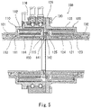
- Patent Literature 1 discloses a fluid loading joint 100 as shown in FIG. 5 , which is intended for liquefied hydrogen and connects vacuum double pipes to each other.
- the fluid loading joint 100 includes a first half 110, which is a movable side of the joint, and a second half 120, which is a fixed side of the joint.
- the first half 110 is provided at an end of a first vacuum double pipe 101
- the second half 120 is provided at an end of a second vacuum double pipe 102.
- the first half 110 includes a first inner pipe 111 and a first outer pipe 112.
- the first outer pipe 112 accommodates the first inner pipe111 therein.
- the second half 120 includes a second inner pipe 121 and a second outer pipe 122.
- the second outer pipe 122 accommodates the second inner pipe 121 therein.
- a first vacuum space 113 is formed between the first inner pipe 111 and the first outer pipe 112, and a first blocking member 114 blocks between the first inner pipe 111 and the first outer pipe 112.
- a second vacuum space 123 is formed between the second inner pipe 121 and the second outer pipe 122, and a second blocking member 124 blocks between the second inner pipe 121 and the second outer pipe 122.
- the first half 110 includes a holder 116, which holds the first outer pipe 112 via bearings, such that the first outer pipe 112 is rotatable.
- An outer flange 126 is provided at the distal end of the second outer pipe 122, and the outer flange 126 is fastened to the holder 116 by bolts 130.
- a first flange 115 is provided at the distal end of the first inner pipe 111, and a second flange 125 is provided at the distal end of the second inner pipe 121.
- the distal end surface of the second flange 125 is a sliding surface facing the first flange 115.
- An inner sealing member 141 and an outer sealing member 142 for preventing the liquefied hydrogen from leaking through a gap between the first flange 115 and the second flange 125 are disposed between the first flange 115 and the second flange 125.
- the first flange 115 is provided with an inner passage that leads a leaked fluid that has leaked beyond the inner sealing member 141 from between the inner sealing member 141 and the outer sealing member 142 to the outer circumferential surface of the first flange.
- the first outer pipe 112 is provided with an outer passage that leads the leaked fluid from the inner side to the outer side of the first outer pipe 112.
- the inner passage and the outer passage are connected by a leakage pipe 150.
- Patent Literature 2 also discloses a known fluid joint.
- PTL 1 Japanese Laid-Open Patent Application Publication No. 2017-19531
- PTL 2 DE 23 31 707 A1
- an object of the present invention is to provide a fluid loading joint whose first half has a simplified structure.
- a fluid loading joint for rotatably connecting double pipes to each other, the fluid loading joint including: a first half including a first inner pipe, a first outer pipe, and a holder, the first inner pipe being provided with a first flange, the first outer pipe accommodating the first inner pipe therein, the holder holding the first outer pipe such that the first outer pipe is rotatable; a second half including a sliding surface facing the first flange, the second half including a second inner pipe and a second outer pipe, the second inner pipe being provided with a second flange, the second outer pipe accommodating the second inner pipe therein and being provided with an outer flange that is fastened to the holder; an inner sealing member and an outer sealing member that are disposed between the first flange and the sliding surface; an inner passage provided in the second flange, the inner passage leading a leaked fluid from between the inner sealing member and the outer sealing member to an outer circumferential surface of the second
- the discharge route of the leaked fluid is formed in the fixed-side second half. This makes it possible to simplify the structure of the movable-side first half, which incorporates bearings therein.
- the outer passage may be located at a position that is different from a position of the inner passage in a circumferential direction.
- the leakage pipe may connect the inner passage and the outer passage while bending.
- the fluid flowing through the inside of the first inner pipe and the second inner pipe is a fluid having an extremely low temperature, such as liquefied hydrogen
- the first inner pipe and the second inner pipe thermally contract to a great degree.
- the leakage pipe since the leakage pipe includes bend portions, the thermal contraction of the second inner pipe can be absorbed by bending deformation occurring at the bend portions.
- the first half may include a first blocking member that blocks between the first inner pipe and the first outer pipe.
- the second half may include a second blocking member that blocks between the second inner pipe and the second outer pipe, the second blocking member forming a gas space between the first blocking member and the second blocking member, the gas space being filled with gas.
- the leakage pipe may be disposed in the gas space.
- the second half may include: an annular spacer interposed between the first flange and the second flange and forming the sliding surface; and an annular insulator sandwiched between the spacer and the second flange.
- the insulator may be provided with a through-hole that communicates with the inner passage.
- the spacer may be provided with an introduction passage that is open at the sliding surface between the inner sealing member and the outer sealing member, the introduction passage communicating with the through-hole. This configuration makes it possible to electrically insulate between the first flange and the second flange.
- the present invention provides a fluid loading joint whose first half has a simplified structure.
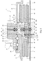
- FIG. 1 to FIG. 3 show a fluid loading joint 1 intended for a low-temperature fluid according to one embodiment of the present invention.
- the fluid loading joint 1 is incorporated in fluid loading equipment (a loading arm) that is installed at, for example, a harbor or port and that is connected to, for example, a liquefied gas carrier ship.
- fluid loading equipment a loading arm
- the low-temperature fluid for which the fluid loading joint 1 is intended, is liquefied hydrogen.
- the low-temperature fluid may be a different low-temperature liquid, such as LNG, or may be low-temperature gas.
- the fluid loading joint 1 rotatably connects a first vacuum double pipe 11 and a second vacuum double pipe 14 to each other.
- the fluid loading joint 1 includes a first half 2, which is a movable side of the joint, and a second half 3, which is a fixed side of the joint.
- the first half 2 is provided at an end of the first vacuum double pipe 11.
- the second half 3 is provided at an end of the second vacuum double pipe 14.
- the first vacuum double pipe 11 includes a first conduit pipe 12 and a first accommodating pipe 13.
- the liquefied hydrogen flows through the inside of the first conduit pipe 12.
- the first accommodating pipe 13 accommodates the first conduit pipe 12 therein.
- a vacuum is drawn on the space between the first conduit pipe 12 and the first accommodating pipe 13.
- the second vacuum double pipe 14 includes a second conduit pipe 15 and a second accommodating pipe 16.
- the liquefied hydrogen flows through the inside of the second conduit pipe 15.
- the second accommodating pipe 16 accommodates the second conduit pipe 15 therein. A vacuum is drawn on the space between the second conduit pipe 15 and the second accommodating pipe 16.
- the first half 2 includes a first inner pipe 21 and a first outer pipe 22.
- the first outer pipe 22 accommodates the first inner pipe 21 therein.
- the first conduit pipe 12 is joined, for example by welding, to the proximal end of the first inner pipe 21 (i.e., the opposite end from the second half 3).
- the first accommodating pipe 13 is joined, for example by welding, to the proximal end of the first outer pipe 22.
- a first vacuum space 23 is formed between the first inner pipe 21 and the first outer pipe 22. It should be noted that the position of the proximal end of the first inner pipe 21 and the position of the proximal end of the first outer pipe 22 may be shifted from each other in the axial direction.
- the second half 3 includes a second inner pipe 31 and a second outer pipe 32.
- the second outer pipe 32 accommodates the second inner pipe 31 therein.
- the second conduit pipe 15 is joined, for example by welding, to the proximal end of the second inner pipe 31 (i.e., the opposite end from the first half 2).
- the second accommodating pipe 16 is joined, for example by welding, to the proximal end of the second outer pipe 32.
- a second vacuum space 33 is formed between the second inner pipe 31 and the second outer pipe 32. It should be noted that the position of the proximal end of the second inner pipe 31 and the position of the proximal end of the second outer pipe 32 may be shifted from each other in the axial direction.
- the first half 2 further includes a cylindrical holder 25, which holds the first outer pipe 22 via bearings 26, such that the first outer pipe 22 is rotatable. Meanwhile, an outer flange 35 expanding outward in the radial direction is provided at the distal end of the second outer pipe 32 of the second half 3 (i.e., the end facing the first half 2).
- the outer flange 35 is fastened to the holder 25 by bolts 91. That is, the holder 25 is provided with screw holes in which the bolts 91 are screwed. Alternatively, instead of the screw holes, the holder 25 may be provided with insertion holes intended for the bolts 91, and in this case, nuts may be used.
- a first flange 24 expanding outward in the radial direction is provided at the distal end of the first inner pipe 21 (i.e., the end facing the second half 3).
- a second flange 34 expanding outward in the radial direction is provided at the distal end of the second inner pipe 31.
- the first outer pipe 22 and the second outer pipe 32 expand in diameter, except at their proximal end portions. It should be noted that the second outer pipe 32 expands in diameter to a greater degree than the first outer pipe 22, such that the internal diameter of the distal end portion of the second outer pipe 32 is substantially the same as the internal diameter of the holder 25.
- An annular first blocking member 41 blocks between the first inner pipe 21 and the first outer pipe 22.
- the first blocking member 41 is located at a position deeper than the distal end surface of the first flange 24 and the distal end surface of the holder 25.
- the inner end portion of the first blocking member 41 is joined to the proximal end surface of the first flange 24, and the outer end portion of the first blocking member 41 is joined to the inner circumferential surface of the first outer pipe 22 at a position that is slightly shifted from the distal end of the first outer pipe 22 toward the proximal end of the first outer pipe 22.
- the first blocking member 41 includes at least one annular groove 42, which is recessed into the first vacuum space 23 along the first inner pipe 21. It should be noted that, desirably, a plurality of concentric annular grooves 42 are provided such that the first blocking member 41 is bellows-shaped when seen in a cross-sectional view. In the present embodiment, the first blocking member 41 includes two concentric annular grooves 42.
- the space between the first blocking member 41 and the first inner pipe 21, the space between the first blocking member 41 and the first outer pipe 22, and the space between the annular grooves 42 of the first blocking member 41 are part of the aforementioned first vacuum space 23.
- the inside of the annular grooves 42 is filled with helium gas. In this manner, vacuum layers and helium gas layers are alternately formed by the first blocking member 41 in the radial direction.
- an annular second blocking member 43 blocks between the second inner pipe 31 and the second outer pipe 32.
- the second blocking member 43 is located at a position deeper than the distal end surface of the second flange 34 and the distal end surface of the outer flange 35.
- the inner end portion of the second blocking member 43 is joined to the proximal end surface of the second flange 34, and the outer end portion of the second blocking member 43 is joined to the inner circumferential surface of the second outer pipe 32 at a position that is slightly shifted from the distal end of the second outer pipe 32 toward the proximal end of the second outer pipe 32.
- the second blocking member 43 includes at least one annular groove 44, which is recessed into the second vacuum space 33 along the second inner pipe 31. It should be noted that, desirably, a plurality of concentric annular grooves 44 are provided such that the second blocking member 43 is bellows-shaped when seen in a sectional view. In the present embodiment, the second blocking member 43 includes three concentric annular grooves 44.
- the space between the second blocking member 43 and the second inner pipe 31, the space between the second blocking member 43 and the second outer pipe 32, and the spaces between the annular grooves 44 of the second blocking member 43 are part of the aforementioned second vacuum space 33.
- the inside of the annular grooves 44 is filled with helium gas. In this manner, vacuum layers and helium gas layers are alternately formed by the second blocking member 43 in the radial direction.
- the second half 3 is configured to electrically insulate the first vacuum double pipe 11 and the second vacuum double pipe 14 from each other.
- the second half 3 includes: an annular inner spacer 61 and an annular inner insulator 51, which are interposed between the first flange 24 and the second flange 34; and an annular outer spacer 62 and an annular outer insulator 52, which are interposed between the holder 25 and the outer flange 35.
- the inner insulator 51 is sandwiched between the second flange 34 and the inner spacer 61.
- the inner spacer 61 forms a sliding surface 3a. That is, the distal end surface of the inner spacer 61 is the sliding surface 3a facing the first flange 24.
- the inner spacer 61 is fastened to the second flange 34 by bolts 92.
- the inner insulator 51 is provided with insertion holes for the bolts 92.
- the outer insulator 52 is sandwiched between the outer flange 35 and the outer spacer 62.
- the outer insulator 52 and the outer spacer 62 are provided with insertion holes for the aforementioned bolts 91.
- the thickness of the inner insulator 51 is the same as the thickness of the outer insulator 52, and a gap is formed between the inner insulator 51 and the outer insulator 52.
- the thickness of the inner spacer 61 is the same as the thickness of the outer spacer 62, and a gap is formed between the inner spacer 61 and the outer spacer 62.
- the inner insulator 51 and the outer insulator 52 may have different thicknesses from each other, and the inner spacer 61 and the outer spacer 62 may have different thicknesses from each other.
- Each of the inner insulator 51 and the outer insulator 52 is made of an insulating material (e.g., a resin such as commodity plastic or engineering plastic).
- Each of the inner spacer 61 and the outer spacer 62 is made of a metal.
- An inner sealing member 71 and an outer sealing member 72 for preventing the liquefied hydrogen from leaking through a gap between the first flange 24 and the inner spacer 61 (sliding surface 3a) are disposed between the first flange 24 and the inner spacer 61 (sliding surface 3a).
- both the inner sealing member 71 and the outer sealing member 72 are held by the first flange 24.
- one of or both the inner sealing member 71 and the outer sealing member 72 may be held by the inner spacer 61.
- a slight clearance is formed between the first flange 24 and the inner spacer 61, and the inner sealing member 71 and the outer sealing member 72 held by the first flange 24 slide on the inner spacer 61.
- a ring 46 is fitted to the distal end of the first inner pipe 21, such that the ring 46 obscures the inner sealing member 71 from the inside.
- Sealing members 73 for preventing the liquefied hydrogen from leaking through a gap between the inner spacer 61 and the inner insulator 51 are disposed between the inner spacer 61 and the inner insulator 51, and sealing members 74 for preventing the liquefied hydrogen from leaking through a gap between the inner insulator 51 and the second flange 34 are disposed between the inner insulator 51 and the second flange 34.
- These gaps and spaces constitute a gas space 45.
- the gas space 45 is formed between the first blocking member 41 and the second blocking member 43.
- the gas space 45 is filled with helium gas.
- Port members 27 for supplying the helium gas to the gas space 45 through a gap between the first outer pipe 22 and the holder 25 are mounted to the holder 25.
- a sealing member 75 for preventing the entry of outside water is disposed between the first outer pipe 22 and the holder 25.
- Sealing members 76 to 78 for preventing hydrogen gas from leaking to the outside are disposed between the holder 25, the outer spacer 62, the outer insulator 52, and the outer flange 35 so that the hydrogen gas will be prevented from leaking to the outside even when the liquefied hydrogen has leaked into the gas space 45 beyond the sealing members 71 to 74.
- These sealing members 75 to 78 also serve to prevent the helium gas from leaking to the outside.
- the aforementioned bolts 91 which fasten the outer flange 35 to the holder 25, are made of a metal. Accordingly, sleeves 93 made of an insulating material are inserted in the aforementioned insertion holes for the bolts 91, the insertion holes being provided in the outer insulator 52 and the outer spacer 62. Seats 94 made of an insulating material are disposed between the outer flange 35 and washers 95, which contact the heads of the respective bolts 91.
- the aforementioned bolts 92 which fasten the inner spacer 61 to the second flange 34, are made of an insulating material.
- the bolts 92 may be made of a metal, and the same insulation measures as those adopted for the bolts 91 may be adopted for the bolts 92.
- the present embodiment further adopts a configuration for discharging, to the outside, a leaked fluid present between the inner sealing member 71 and the outer sealing member 72 at the sliding part between the first flange 24 and the inner spacer 61 (sliding surface 3a).
- the leaked fluid is either the liquefied hydrogen that has leaked beyond the inner sealing member 71 or hydrogen gas that results from evaporation of the liquefied hydrogen that has leaked beyond the inner sealing member 71.
- the inner spacer 61 is provided with an introduction passage 63; the inner insulator 51 is provided with a through-hole 53; and the second flange 34 is provided with an inner passage 36.
- the outer flange 35 is provided with an outer passage 37. Between the second flange 34 and the outer flange 35, the inner passage 36 and the outer passage 37 are connected by a leakage pipe 8.
- the leakage pipe 8 is disposed in the gas space 45.
- the introduction passage 63 provided in the inner spacer 61 is open at the sliding surface 3a between the inner sealing member 71 and the outer sealing member 72, and extends from the sliding surface 3a in the axial direction of the second inner pipe 31. Specifically, the introduction passage 63 leads the leaked fluid, which has leaked beyond the inner sealing member 71, from between the inner sealing member 71 and the outer sealing member 72 to the proximal end surface of the inner spacer 61.
- the through-hole 53 provided in the inner insulator 51 communicates with the introduction passage 63.
- the inner passage 36 provided in the second flange 34 communicates with the through-hole 53, and leads the leaked fluid to the outer circumferential surface of the second flange 34.
- the inner passage 36 extends from the distal end surface of the second flange 34 in the axial direction of the second inner pipe 31, and then bends by 90 degrees toward the outer circumferential surface of the second flange 34.
- the outer circumferential surface of the second flange 34 is provided with a recess 34a, and the downstream end of the inner passage 36 is open at the bottom of the recess 34a.
- the outer passage 37 leads the leaked fluid from the inner side to the outer side of the second outer pipe 32.
- the upstream end of the outer passage 37 is open at the inner circumferential surface of the outer flange 35, and the downstream end of the outer passage 37 is open at the outer circumferential surface of the outer flange 35.
- the downstream end of the outer passage 37 may be open at the proximal end surface of the outer flange 35.
- An unshown discharge pipe is connected to the downstream end of the outer passage 37.
- the outer passage 37 is located at a position that is different from the position of the inner passage 36 in the circumferential direction. Specifically, in the circumferential direction, the outer passage 37 is located at a position that is shifted from the inner passage 36 by 90 degrees. Further, in the present embodiment, as shown in FIG. 2 , the position of the outer passage 37 is different from the position of the inner passage 36 also in the axial direction of the second inner pipe 31.
- the leakage pipe 8 connects the inner passage 36 and the outer passage 37 while bending.
- the leakage pipe 8 includes at least one L-shaped portion.
- the leakage pipe 8 includes: a first L-shaped portion 81 connected to the second flange 34; a second L-shaped portion 83 connected to the outer flange 35; and a straight transition portion 82 positioned between the first L-shaped portion 81 and the second L-shaped portion 83.
- the first L-shaped portion 81 includes a first bend portion that bends by 90 degrees between two straight portions.
- a portion that connects the first L-shaped portion 81 and the transition portion 82 is a second bend portion that bends by about 45 degrees.
- a portion that connects the transition portion 82 and the second L-shaped portion 83 is a third bend portion that bends by about 45 degrees.
- the second L-shaped portion 83 includes a fourth bend portion that bends by 90 degrees between two straight portions.
- the outer circumferential surface of the second flange 34 is provided also with a recess 34b at a position corresponding to the outer passage 37.
- the outer circumferential surface of the second flange 34 is provided with a cutout 34c between the recess 34a and the recess 34b in order to avoid interference with the transition portion 82.
- the discharge route of the leaked fluid is formed in the fixed-side second half 3. This makes it possible to simplify the structure of the movable-side first half 2, which incorporates the bearings 26 therein.
- the fluid flowing through the inside of the first inner pipe 21 and the second inner pipe 31 is liquefied hydrogen having an extremely low temperature.
- the leakage pipe 8 since the leakage pipe 8 includes the bend portions, thermal contraction of the second inner pipe 31 can be absorbed by bending deformation occurring at the bend portions.
- the second half 3 includes the inner spacer 61, which is provided with the introduction passage 63, and the inner insulator 51, which is provided with the through-hole 53. This makes it possible to electrically insulate between the first flange 24 and the second flange 34.
- the outer spacer 62 may be eliminated, and either one of the first outer pipe 22 or the second outer pipe 32 may be made longer by a length corresponding to the thickness of the outer spacer 62.
- the inner and outer spacers 61 and 62 as well as the inner and outer insulators 51 and 52 may be eliminated, and the distal end surface of the second flange 34 may serve as the sliding surface 3a.
- the gas that fills the gas space 45 can be suitably selected (e.g., nitrogen gas) in accordance with the low-temperature fluid for which the fluid loading joint 1 is intended.
- the fluid loading joint 1 does not necessarily connect vacuum double pipes to each other, but may connect other types of double pipes to each other.
Landscapes
- Engineering & Computer Science (AREA)
- General Engineering & Computer Science (AREA)
- Mechanical Engineering (AREA)
- Joints Allowing Movement (AREA)
- Quick-Acting Or Multi-Walled Pipe Joints (AREA)
- Thermal Insulation (AREA)
- Loading And Unloading Of Fuel Tanks Or Ships (AREA)
Applications Claiming Priority (2)
| Application Number | Priority Date | Filing Date | Title |
|---|---|---|---|
| JP2017254140A JP7137309B2 (ja) | 2017-12-28 | 2017-12-28 | 流体荷役継手 |
| PCT/JP2018/047907 WO2019131784A1 (ja) | 2017-12-28 | 2018-12-26 | 流体荷役継手 |
Publications (3)
| Publication Number | Publication Date |
|---|---|
| EP3734133A1 EP3734133A1 (en) | 2020-11-04 |
| EP3734133A4 EP3734133A4 (en) | 2021-09-29 |
| EP3734133B1 true EP3734133B1 (en) | 2022-11-02 |
Family
ID=67066522
Family Applications (1)
| Application Number | Title | Priority Date | Filing Date |
|---|---|---|---|
| EP18894254.4A Active EP3734133B1 (en) | 2017-12-28 | 2018-12-26 | Fluid loading joint |
Country Status (6)
| Country | Link |
|---|---|
| US (1) | US11608923B2 (enExample) |
| EP (1) | EP3734133B1 (enExample) |
| JP (1) | JP7137309B2 (enExample) |
| CN (1) | CN111601996B (enExample) |
| DK (1) | DK3734133T3 (enExample) |
| WO (1) | WO2019131784A1 (enExample) |
Families Citing this family (4)
| Publication number | Priority date | Publication date | Assignee | Title |
|---|---|---|---|---|
| GB2607013A (en) | 2021-05-20 | 2022-11-30 | Airbus Operations Ltd | Coupling for vacuum-insulated piping |
| FR3128759A1 (fr) * | 2021-10-28 | 2023-05-05 | Airbus | Ensemble de connexion optimise entre deux portions d’une canalisation cryogenique, comprenant une double barriere d’etancheite, une chambre d’expansion de fluide et un detecteur de presence du fluide dans ladite chambre. |
| CN114593289A (zh) * | 2022-03-31 | 2022-06-07 | 中海石油气电集团有限责任公司 | 一种lng低温卸料系统旋转接头装置 |
| NL2031473B1 (en) | 2022-04-01 | 2023-10-24 | Kanon Loading Equipment B V | Fluid loading coupling for rotatable coupling of fluid conduits for cryogenic fluids |
Family Cites Families (23)
| Publication number | Priority date | Publication date | Assignee | Title |
|---|---|---|---|---|
| US236519A (en) * | 1881-01-11 | Hamilton Mark K | Receptable | |
| US2957709A (en) * | 1946-03-01 | 1960-10-25 | Charles W Skarstrom | Sealing means for relatively rotatable members |
| US2877026A (en) * | 1954-02-09 | 1959-03-10 | Crane Packing Co | Sealing device for a swivel joint having plural fluid passages |
| FR1230498A (fr) * | 1959-02-12 | 1960-09-16 | Prec Ind | Broche de machine-outil à moteur hydraulique incorporé |
| US3180661A (en) * | 1962-12-06 | 1965-04-27 | Gordon H Porath | Rotary hydraulic fitting |
| FR1399258A (fr) * | 1964-06-19 | 1965-05-14 | Worthington Corp | Raccord pour canalisation de transport de fluide |
| US3775989A (en) * | 1971-03-31 | 1973-12-04 | Amtek Inc | Rotary cryogenic couplings |
| JPS5026935A (enExample) * | 1973-06-16 | 1975-03-20 | ||
| US4040338A (en) * | 1976-06-14 | 1977-08-09 | Logansport Machine Co., Inc. | Fluid supply distributor |
| FR2418405A1 (fr) * | 1978-02-23 | 1979-09-21 | Fmc Corp | Joint d'articulation pour tubes, notamment pour tubes de transport de produits dangereux |
| JPS5518443U (enExample) * | 1978-07-25 | 1980-02-05 | ||
| JPS5669318A (en) * | 1979-11-10 | 1981-06-10 | Nippon Steel Corp | Rotating joint for converter |
| DE3819390C2 (de) * | 1988-06-07 | 1994-05-26 | Glyco Antriebstechnik Gmbh | Hydrostatische Drehdurchführung |
| DE4103376C1 (enExample) * | 1991-02-05 | 1992-08-06 | Ott Maschinentechnik Gmbh, 8960 Kempten, De | |
| WO1998015772A1 (en) * | 1996-10-08 | 1998-04-16 | Process Systems International, Inc. | Swivel bayonet joint, system and method for cryogenic fluids |
| JP2975923B1 (ja) * | 1998-05-22 | 1999-11-10 | 日本ピラー工業株式会社 | 回転継手装置 |
| JP4189181B2 (ja) * | 2002-08-22 | 2008-12-03 | イーグル工業株式会社 | ロータリージョイント |
| WO2007074721A1 (ja) * | 2005-12-28 | 2007-07-05 | Eagle Industry Co., Ltd. | ロータリージョイント |
| CN103090181B (zh) * | 2013-02-04 | 2015-04-22 | 连云港远洋流体装卸设备有限公司 | 船用低温流体装卸设备 |
| CN103629459A (zh) * | 2013-12-16 | 2014-03-12 | 羊宸机械(上海)有限公司 | 轴向密封真空绝热式超低温旋转接头 |
| JP6396264B2 (ja) * | 2015-07-10 | 2018-09-26 | 東京貿易エンジニアリング株式会社 | 液体水素用流体荷役装置 |
| CN105972360B (zh) * | 2016-07-06 | 2018-08-21 | 大连沃森达智能仪器有限公司 | Lng专用快速接头 |
| MX2020003712A (es) * | 2017-10-09 | 2020-07-22 | Deublin Co | Union giratoria de pasaje multiple. |
-
2017
- 2017-12-28 JP JP2017254140A patent/JP7137309B2/ja active Active
-
2018
- 2018-12-26 EP EP18894254.4A patent/EP3734133B1/en active Active
- 2018-12-26 WO PCT/JP2018/047907 patent/WO2019131784A1/ja not_active Ceased
- 2018-12-26 US US16/958,816 patent/US11608923B2/en active Active
- 2018-12-26 DK DK18894254.4T patent/DK3734133T3/da active
- 2018-12-26 CN CN201880083746.XA patent/CN111601996B/zh active Active
Also Published As
| Publication number | Publication date |
|---|---|
| JP7137309B2 (ja) | 2022-09-14 |
| EP3734133A4 (en) | 2021-09-29 |
| CN111601996A (zh) | 2020-08-28 |
| US20210071795A1 (en) | 2021-03-11 |
| JP2019120287A (ja) | 2019-07-22 |
| US11608923B2 (en) | 2023-03-21 |
| EP3734133A1 (en) | 2020-11-04 |
| CN111601996B (zh) | 2022-05-17 |
| WO2019131784A1 (ja) | 2019-07-04 |
| DK3734133T3 (da) | 2023-01-23 |
Similar Documents
| Publication | Publication Date | Title |
|---|---|---|
| EP3734131B1 (en) | Fluid loading joint and fluid loading equipment | |
| EP3734133B1 (en) | Fluid loading joint | |
| JP2021113614A (ja) | 追加的な真空エンクロージャを備えるジョンストンカプリング | |
| EP3875827B1 (en) | Emergency release mechanism for fluid loading equipment | |
| CN113329939A (zh) | 船舶发动机燃料供给用液化天然气输送管 | |
| JP6480693B2 (ja) | 低温流体用真空断熱二重管の継手構造 | |
| EP3798495B1 (en) | Insulation device for low-temperature pipe | |
| JP6053941B2 (ja) | 加圧下の流体を移送する導管結合体 | |
| US4106796A (en) | Connector for duct systems for low temperature fluids | |
| JP2021113615A (ja) | ガルバニック絶縁を有するジョンストンカプリング | |
| US10113683B2 (en) | Transfer line for cryogenic liquid | |
| EP1837970B1 (en) | Superconducting cable terminal structure | |
| JP5952714B2 (ja) | 冷媒給排装置およびそれを備えた超電導回転機装置 | |
| JP7692389B2 (ja) | 蓄圧器 | |
| JP7667286B2 (ja) | 深冷容器の圧力増加装置及び深冷容器 | |
| CN112460471A (zh) | 低温储罐 | |
| WO2024079830A1 (ja) | 極低温流体移送用配管ユニット | |
| CN102147037A (zh) | 新型复合式补偿器 | |
| CN211013276U (zh) | 一种氮化硅热电偶保护管 | |
| AU2023369085A1 (en) | Storage container | |
| CN118896198A (zh) | 一种真空绝热双壁管的支撑结构及lng燃料罐用双壁管 | |
| ITTO20120322A1 (it) | Giunto per compensare azioni di torsione in una tubazione |
Legal Events
| Date | Code | Title | Description |
|---|---|---|---|
| STAA | Information on the status of an ep patent application or granted ep patent |
Free format text: STATUS: THE INTERNATIONAL PUBLICATION HAS BEEN MADE |
|
| PUAI | Public reference made under article 153(3) epc to a published international application that has entered the european phase |
Free format text: ORIGINAL CODE: 0009012 |
|
| STAA | Information on the status of an ep patent application or granted ep patent |
Free format text: STATUS: REQUEST FOR EXAMINATION WAS MADE |
|
| 17P | Request for examination filed |
Effective date: 20200715 |
|
| AK | Designated contracting states |
Kind code of ref document: A1 Designated state(s): AL AT BE BG CH CY CZ DE DK EE ES FI FR GB GR HR HU IE IS IT LI LT LU LV MC MK MT NL NO PL PT RO RS SE SI SK SM TR |
|
| AX | Request for extension of the european patent |
Extension state: BA ME |
|
| DAV | Request for validation of the european patent (deleted) | ||
| DAX | Request for extension of the european patent (deleted) | ||
| RAP1 | Party data changed (applicant data changed or rights of an application transferred) |
Owner name: KAWASAKI JUKOGYO KABUSHIKI KAISHA Owner name: TB GLOBAL TECHNOLOGIES LTD. |
|
| A4 | Supplementary search report drawn up and despatched |
Effective date: 20210827 |
|
| RIC1 | Information provided on ipc code assigned before grant |
Ipc: B67D 9/00 20100101ALI20210823BHEP Ipc: F16L 59/075 20060101ALI20210823BHEP Ipc: F16L 39/04 20060101ALI20210823BHEP Ipc: F16L 27/08 20060101AFI20210823BHEP |
|
| GRAP | Despatch of communication of intention to grant a patent |
Free format text: ORIGINAL CODE: EPIDOSNIGR1 |
|
| STAA | Information on the status of an ep patent application or granted ep patent |
Free format text: STATUS: GRANT OF PATENT IS INTENDED |
|
| INTG | Intention to grant announced |
Effective date: 20220513 |
|
| GRAS | Grant fee paid |
Free format text: ORIGINAL CODE: EPIDOSNIGR3 |
|
| GRAA | (expected) grant |
Free format text: ORIGINAL CODE: 0009210 |
|
| STAA | Information on the status of an ep patent application or granted ep patent |
Free format text: STATUS: THE PATENT HAS BEEN GRANTED |
|
| AK | Designated contracting states |
Kind code of ref document: B1 Designated state(s): AL AT BE BG CH CY CZ DE DK EE ES FI FR GB GR HR HU IE IS IT LI LT LU LV MC MK MT NL NO PL PT RO RS SE SI SK SM TR |
|
| REG | Reference to a national code |
Ref country code: GB Ref legal event code: FG4D |
|
| REG | Reference to a national code |
Ref country code: CH Ref legal event code: EP Ref country code: AT Ref legal event code: REF Ref document number: 1528971 Country of ref document: AT Kind code of ref document: T Effective date: 20221115 |
|
| REG | Reference to a national code |
Ref country code: DE Ref legal event code: R096 Ref document number: 602018042720 Country of ref document: DE |
|
| REG | Reference to a national code |
Ref country code: IE Ref legal event code: FG4D |
|
| REG | Reference to a national code |
Ref country code: NL Ref legal event code: FP |
|
| REG | Reference to a national code |
Ref country code: DK Ref legal event code: T3 Effective date: 20230118 |
|
| REG | Reference to a national code |
Ref country code: SE Ref legal event code: TRGR |
|
| REG | Reference to a national code |
Ref country code: LT Ref legal event code: MG9D |
|
| REG | Reference to a national code |
Ref country code: BE Ref legal event code: PD Owner name: T.EN LOADING SYSTEMS S.A.S.; FR Free format text: DETAILS ASSIGNMENT: CHANGE OF OWNER(S), ASSIGNMENT Effective date: 20230213 |
|
| RAP2 | Party data changed (patent owner data changed or rights of a patent transferred) |
Owner name: T.EN LOADING SYSTEMS S.A.S. Owner name: TB GLOBAL TECHNOLOGIES LTD. Owner name: KAWASAKI JUKOGYO KABUSHIKI KAISHA |
|
| REG | Reference to a national code |
Ref country code: NL Ref legal event code: PD Owner name: T.EN LOADING SYSTEMS S.A.S.; FR Free format text: DETAILS ASSIGNMENT: CHANGE OF OWNER(S), ASSIGNMENT; FORMER OWNER NAME: TB GLOBAL TECHNOLOGIES LTD. Effective date: 20230221 |
|
| REG | Reference to a national code |
Ref country code: GB Ref legal event code: 732E Free format text: REGISTERED BETWEEN 20230216 AND 20230222 |
|
| REG | Reference to a national code |
Ref country code: NO Ref legal event code: T2 Effective date: 20221102 |
|
| REG | Reference to a national code |
Ref country code: DE Ref legal event code: R081 Ref document number: 602018042720 Country of ref document: DE Owner name: TB GLOBAL TECHNOLOGIES LTD., JP Free format text: FORMER OWNERS: KAWASAKI JUKOGYO KABUSHIKI KAISHA, KOBE-SHI, HYOGO, JP; TB GLOBAL TECHNOLOGIES LTD., TOKYO, JP Ref country code: DE Ref legal event code: R081 Ref document number: 602018042720 Country of ref document: DE Owner name: T.EN LOADING SYSTEMS S.A.S., FR Free format text: FORMER OWNERS: KAWASAKI JUKOGYO KABUSHIKI KAISHA, KOBE-SHI, HYOGO, JP; TB GLOBAL TECHNOLOGIES LTD., TOKYO, JP Ref country code: DE Ref legal event code: R081 Ref document number: 602018042720 Country of ref document: DE Owner name: KAWASAKI JUKOGYO KABUSHIKI KAISHA, KOBE-SHI, JP Free format text: FORMER OWNERS: KAWASAKI JUKOGYO KABUSHIKI KAISHA, KOBE-SHI, HYOGO, JP; TB GLOBAL TECHNOLOGIES LTD., TOKYO, JP |
|
| REG | Reference to a national code |
Ref country code: AT Ref legal event code: MK05 Ref document number: 1528971 Country of ref document: AT Kind code of ref document: T Effective date: 20221102 |
|
| PG25 | Lapsed in a contracting state [announced via postgrant information from national office to epo] |
Ref country code: PT Free format text: LAPSE BECAUSE OF FAILURE TO SUBMIT A TRANSLATION OF THE DESCRIPTION OR TO PAY THE FEE WITHIN THE PRESCRIBED TIME-LIMIT Effective date: 20230302 Ref country code: LT Free format text: LAPSE BECAUSE OF FAILURE TO SUBMIT A TRANSLATION OF THE DESCRIPTION OR TO PAY THE FEE WITHIN THE PRESCRIBED TIME-LIMIT Effective date: 20221102 Ref country code: FI Free format text: LAPSE BECAUSE OF FAILURE TO SUBMIT A TRANSLATION OF THE DESCRIPTION OR TO PAY THE FEE WITHIN THE PRESCRIBED TIME-LIMIT Effective date: 20221102 Ref country code: ES Free format text: LAPSE BECAUSE OF FAILURE TO SUBMIT A TRANSLATION OF THE DESCRIPTION OR TO PAY THE FEE WITHIN THE PRESCRIBED TIME-LIMIT Effective date: 20221102 Ref country code: AT Free format text: LAPSE BECAUSE OF FAILURE TO SUBMIT A TRANSLATION OF THE DESCRIPTION OR TO PAY THE FEE WITHIN THE PRESCRIBED TIME-LIMIT Effective date: 20221102 |
|
| PG25 | Lapsed in a contracting state [announced via postgrant information from national office to epo] |
Ref country code: RS Free format text: LAPSE BECAUSE OF FAILURE TO SUBMIT A TRANSLATION OF THE DESCRIPTION OR TO PAY THE FEE WITHIN THE PRESCRIBED TIME-LIMIT Effective date: 20221102 Ref country code: PL Free format text: LAPSE BECAUSE OF FAILURE TO SUBMIT A TRANSLATION OF THE DESCRIPTION OR TO PAY THE FEE WITHIN THE PRESCRIBED TIME-LIMIT Effective date: 20221102 Ref country code: LV Free format text: LAPSE BECAUSE OF FAILURE TO SUBMIT A TRANSLATION OF THE DESCRIPTION OR TO PAY THE FEE WITHIN THE PRESCRIBED TIME-LIMIT Effective date: 20221102 Ref country code: IS Free format text: LAPSE BECAUSE OF FAILURE TO SUBMIT A TRANSLATION OF THE DESCRIPTION OR TO PAY THE FEE WITHIN THE PRESCRIBED TIME-LIMIT Effective date: 20230302 Ref country code: HR Free format text: LAPSE BECAUSE OF FAILURE TO SUBMIT A TRANSLATION OF THE DESCRIPTION OR TO PAY THE FEE WITHIN THE PRESCRIBED TIME-LIMIT Effective date: 20221102 Ref country code: GR Free format text: LAPSE BECAUSE OF FAILURE TO SUBMIT A TRANSLATION OF THE DESCRIPTION OR TO PAY THE FEE WITHIN THE PRESCRIBED TIME-LIMIT Effective date: 20230203 |
|
| PG25 | Lapsed in a contracting state [announced via postgrant information from national office to epo] |
Ref country code: SM Free format text: LAPSE BECAUSE OF FAILURE TO SUBMIT A TRANSLATION OF THE DESCRIPTION OR TO PAY THE FEE WITHIN THE PRESCRIBED TIME-LIMIT Effective date: 20221102 Ref country code: RO Free format text: LAPSE BECAUSE OF FAILURE TO SUBMIT A TRANSLATION OF THE DESCRIPTION OR TO PAY THE FEE WITHIN THE PRESCRIBED TIME-LIMIT Effective date: 20221102 Ref country code: EE Free format text: LAPSE BECAUSE OF FAILURE TO SUBMIT A TRANSLATION OF THE DESCRIPTION OR TO PAY THE FEE WITHIN THE PRESCRIBED TIME-LIMIT Effective date: 20221102 Ref country code: CZ Free format text: LAPSE BECAUSE OF FAILURE TO SUBMIT A TRANSLATION OF THE DESCRIPTION OR TO PAY THE FEE WITHIN THE PRESCRIBED TIME-LIMIT Effective date: 20221102 |
|
| REG | Reference to a national code |
Ref country code: CH Ref legal event code: PL |
|
| REG | Reference to a national code |
Ref country code: DE Ref legal event code: R097 Ref document number: 602018042720 Country of ref document: DE |
|
| PG25 | Lapsed in a contracting state [announced via postgrant information from national office to epo] |
Ref country code: SK Free format text: LAPSE BECAUSE OF FAILURE TO SUBMIT A TRANSLATION OF THE DESCRIPTION OR TO PAY THE FEE WITHIN THE PRESCRIBED TIME-LIMIT Effective date: 20221102 Ref country code: LU Free format text: LAPSE BECAUSE OF NON-PAYMENT OF DUE FEES Effective date: 20221226 Ref country code: AL Free format text: LAPSE BECAUSE OF FAILURE TO SUBMIT A TRANSLATION OF THE DESCRIPTION OR TO PAY THE FEE WITHIN THE PRESCRIBED TIME-LIMIT Effective date: 20221102 |
|
| PLBE | No opposition filed within time limit |
Free format text: ORIGINAL CODE: 0009261 |
|
| STAA | Information on the status of an ep patent application or granted ep patent |
Free format text: STATUS: NO OPPOSITION FILED WITHIN TIME LIMIT |
|
| 26N | No opposition filed |
Effective date: 20230803 |
|
| PG25 | Lapsed in a contracting state [announced via postgrant information from national office to epo] |
Ref country code: LI Free format text: LAPSE BECAUSE OF NON-PAYMENT OF DUE FEES Effective date: 20221231 Ref country code: IE Free format text: LAPSE BECAUSE OF NON-PAYMENT OF DUE FEES Effective date: 20221226 Ref country code: CH Free format text: LAPSE BECAUSE OF NON-PAYMENT OF DUE FEES Effective date: 20221231 |
|
| PG25 | Lapsed in a contracting state [announced via postgrant information from national office to epo] |
Ref country code: SI Free format text: LAPSE BECAUSE OF FAILURE TO SUBMIT A TRANSLATION OF THE DESCRIPTION OR TO PAY THE FEE WITHIN THE PRESCRIBED TIME-LIMIT Effective date: 20221102 |
|
| PG25 | Lapsed in a contracting state [announced via postgrant information from national office to epo] |
Ref country code: CY Free format text: LAPSE BECAUSE OF FAILURE TO SUBMIT A TRANSLATION OF THE DESCRIPTION OR TO PAY THE FEE WITHIN THE PRESCRIBED TIME-LIMIT Effective date: 20221102 |
|
| PG25 | Lapsed in a contracting state [announced via postgrant information from national office to epo] |
Ref country code: MK Free format text: LAPSE BECAUSE OF FAILURE TO SUBMIT A TRANSLATION OF THE DESCRIPTION OR TO PAY THE FEE WITHIN THE PRESCRIBED TIME-LIMIT Effective date: 20221102 Ref country code: HU Free format text: LAPSE BECAUSE OF FAILURE TO SUBMIT A TRANSLATION OF THE DESCRIPTION OR TO PAY THE FEE WITHIN THE PRESCRIBED TIME-LIMIT; INVALID AB INITIO Effective date: 20181226 |
|
| PG25 | Lapsed in a contracting state [announced via postgrant information from national office to epo] |
Ref country code: MC Free format text: LAPSE BECAUSE OF FAILURE TO SUBMIT A TRANSLATION OF THE DESCRIPTION OR TO PAY THE FEE WITHIN THE PRESCRIBED TIME-LIMIT Effective date: 20221102 |
|
| PG25 | Lapsed in a contracting state [announced via postgrant information from national office to epo] |
Ref country code: MC Free format text: LAPSE BECAUSE OF FAILURE TO SUBMIT A TRANSLATION OF THE DESCRIPTION OR TO PAY THE FEE WITHIN THE PRESCRIBED TIME-LIMIT Effective date: 20221102 |
|
| PG25 | Lapsed in a contracting state [announced via postgrant information from national office to epo] |
Ref country code: BG Free format text: LAPSE BECAUSE OF FAILURE TO SUBMIT A TRANSLATION OF THE DESCRIPTION OR TO PAY THE FEE WITHIN THE PRESCRIBED TIME-LIMIT Effective date: 20221102 |
|
| PG25 | Lapsed in a contracting state [announced via postgrant information from national office to epo] |
Ref country code: MT Free format text: LAPSE BECAUSE OF FAILURE TO SUBMIT A TRANSLATION OF THE DESCRIPTION OR TO PAY THE FEE WITHIN THE PRESCRIBED TIME-LIMIT Effective date: 20221102 |
|
| PGFP | Annual fee paid to national office [announced via postgrant information from national office to epo] |
Ref country code: DE Payment date: 20241029 Year of fee payment: 7 |
|
| PGFP | Annual fee paid to national office [announced via postgrant information from national office to epo] |
Ref country code: NO Payment date: 20241211 Year of fee payment: 7 |
|
| PGFP | Annual fee paid to national office [announced via postgrant information from national office to epo] |
Ref country code: DK Payment date: 20241212 Year of fee payment: 7 |
|
| PGFP | Annual fee paid to national office [announced via postgrant information from national office to epo] |
Ref country code: BE Payment date: 20241120 Year of fee payment: 7 |
|
| PGFP | Annual fee paid to national office [announced via postgrant information from national office to epo] |
Ref country code: GB Payment date: 20241107 Year of fee payment: 7 |
|
| PGFP | Annual fee paid to national office [announced via postgrant information from national office to epo] |
Ref country code: FR Payment date: 20241111 Year of fee payment: 7 |
|
| PGFP | Annual fee paid to national office [announced via postgrant information from national office to epo] |
Ref country code: IT Payment date: 20241112 Year of fee payment: 7 |
|
| PGFP | Annual fee paid to national office [announced via postgrant information from national office to epo] |
Ref country code: SE Payment date: 20241114 Year of fee payment: 7 |
|
| PG25 | Lapsed in a contracting state [announced via postgrant information from national office to epo] |
Ref country code: TR Free format text: LAPSE BECAUSE OF FAILURE TO SUBMIT A TRANSLATION OF THE DESCRIPTION OR TO PAY THE FEE WITHIN THE PRESCRIBED TIME-LIMIT Effective date: 20221102 |
|
| PGFP | Annual fee paid to national office [announced via postgrant information from national office to epo] |
Ref country code: NL Payment date: 20251112 Year of fee payment: 8 |