EP3734004B1 - Vehicle door latch device - Google Patents
Vehicle door latch device Download PDFInfo
- Publication number
- EP3734004B1 EP3734004B1 EP18893757.7A EP18893757A EP3734004B1 EP 3734004 B1 EP3734004 B1 EP 3734004B1 EP 18893757 A EP18893757 A EP 18893757A EP 3734004 B1 EP3734004 B1 EP 3734004B1
- Authority
- EP
- European Patent Office
- Prior art keywords
- latch
- ratchet
- restraint
- vehicle door
- lever
- Prior art date
- Legal status (The legal status is an assumption and is not a legal conclusion. Google has not performed a legal analysis and makes no representation as to the accuracy of the status listed.)
- Active
Links
Images










Classifications
-
- E—FIXED CONSTRUCTIONS
- E05—LOCKS; KEYS; WINDOW OR DOOR FITTINGS; SAFES
- E05B—LOCKS; ACCESSORIES THEREFOR; HANDCUFFS
- E05B81/00—Power-actuated vehicle locks
- E05B81/24—Power-actuated vehicle locks characterised by constructional features of the actuator or the power transmission
- E05B81/32—Details of the actuator transmission
- E05B81/42—Cams
-
- E—FIXED CONSTRUCTIONS
- E05—LOCKS; KEYS; WINDOW OR DOOR FITTINGS; SAFES
- E05B—LOCKS; ACCESSORIES THEREFOR; HANDCUFFS
- E05B81/00—Power-actuated vehicle locks
- E05B81/12—Power-actuated vehicle locks characterised by the function or purpose of the powered actuators
- E05B81/14—Power-actuated vehicle locks characterised by the function or purpose of the powered actuators operating on bolt detents, e.g. for unlatching the bolt
-
- E—FIXED CONSTRUCTIONS
- E05—LOCKS; KEYS; WINDOW OR DOOR FITTINGS; SAFES
- E05B—LOCKS; ACCESSORIES THEREFOR; HANDCUFFS
- E05B83/00—Vehicle locks specially adapted for particular types of wing or vehicle
- E05B83/36—Locks for passenger or like doors
-
- E—FIXED CONSTRUCTIONS
- E05—LOCKS; KEYS; WINDOW OR DOOR FITTINGS; SAFES
- E05B—LOCKS; ACCESSORIES THEREFOR; HANDCUFFS
- E05B85/00—Details of vehicle locks not provided for in groups E05B77/00 - E05B83/00
- E05B85/20—Bolts or detents
- E05B85/24—Bolts rotating about an axis
- E05B85/243—Bolts rotating about an axis with a bifurcated bolt
-
- E—FIXED CONSTRUCTIONS
- E05—LOCKS; KEYS; WINDOW OR DOOR FITTINGS; SAFES
- E05B—LOCKS; ACCESSORIES THEREFOR; HANDCUFFS
- E05B85/00—Details of vehicle locks not provided for in groups E05B77/00 - E05B83/00
- E05B85/20—Bolts or detents
- E05B85/24—Bolts rotating about an axis
- E05B85/26—Cooperation between bolts and detents
Definitions
- the present invention relates to a vehicle door latch apparatus.
- the present invention relates to a vehicle door latch apparatus that reduces release operation force that is required to disengage a ratchet from a latch.
- a ratchet engages a latch that has rotated from an unlatched position to a full-latched position, and thereby prevents the latch from rotating in a releasing direction in order to keep the vehicle door closed (in the full-latched state). Further, in the vehicle door latch apparatus, the ratchet is rotated in the latch releasing direction (a direction opposite to the latch engaging direction), by a manual release operation force from a door opening handle or by an electric release operation force from a power release mechanism, to disengage the ratchet from the latch, and thereby allows the latch to rotate in the releasing direction to make the vehicle door openable.
- the latch is strongly pressed against the ratchet in the full-latched state by being strongly biased in the releasing direction by the resilient force of a latch spring and by the repulsive force of a seal member that is provided between the door and the vehicle body.
- the ratchet is also biased in the latch engaging direction by the resilient force of a ratchet spring.
- the friction force, which is generated by the latch being pressed against ratchet, and the elasticity of the ratchet spring act as resistive force against the release operation force, resulting in degradation of the operation feeling when operating the door opening handle and in an increase in the size of the power release mechanism.
- Patent Document 1 discloses a vehicle door latch apparatus that reduces the release operation force for releasing a ratchet from a latch.
- FIG. 13 shows the mechanism for reducing the release operation force in Patent Document 1.
- Latch A is held in the full-latched position by engagement with ratchet B, and ratchet B is prevented from rotating in the latch releasing direction by abutting against ratchet restraint C that is provided on the side of ratchet B.
- ratchet restraint C that is provided on the side of ratchet B.
- Release component force E is set to be higher than the engagement keeping force that keeps ratchet B engaged with latch A, specifically, the sum of the friction force that is generated between latch A and ratchet B and the resilient force of the ratchet spring that biases ratchet B in the latch engaging direction. Therefore, when ratchet restraint C is rotated clockwise by the manual release operation force or by the electric release operation force in order to disengage ratchet restraint C from ratchet B, ratchet B is rotated in the latch releasing direction by release component force E and is pushed out from the latch engaging position to a latch disengaging position. As a result, ratchet B is disengaged from latch A, and the door is made openable.
- the friction force that is generated between ratchet restraint C and ratchet B acts as force that is resistive against the release operation force.
- the resistive force is considerably reduced as compared to the force that is resistive against the release operation force in a conventional apparatus, that is, the friction force that is generated by the latch pressing the ratchet and the resistive force that arises from the elasticity of the ratchet spring, and accordingly, the release operation force can be reduced considerably.
- ratchet B cannot rotate in the latch releasing direction unless ratchet restraint C is rotated clockwise by the manual release operation force or by the electric release operation force in order to disengage ratchet restraint C from ratchet B. Due to this structural limitation, latch A can only be provided with one engaging portion F that engages ratchet B.
- the present invention provides a vehicle door latch apparatus as defined in the appended independent claims.
- Optional features are defined in the appended dependent claims.
- a vehicle door latch apparatus according to a first aspect of the disclosure comprises:
- the latch has a full latch engaging portion that is arranged together with the half latch engaging portion.
- the ratchet restraint has a blocking surface, which is an arc surface whose center is positioned at the pin, and an inclined cam surface that extends contiguous with the blocking surface and whose radius from the pin gradually decreases.
- the pole lever is pressed against the base lever in a latch engaging direction by resilient force of a ratchet spring, a coil portion of the ratchet spring is supported by the connecting shaft, one of spring legs of the ratchet spring is engaged with ratchet shaft, and the other is engaged with the pole lever.
- the base lever in the disclosure of the vehicle door latch apparatus of the third aspect, can be rotated from a restricted position, where the base lever is in contact with the blocking surface, to a non-restricted position by the releasing component force.
- the ratchet restraint includes a cam biasing spring that biases the ratchet restraint from the release position toward the block position.
- the inclined cam surface of the ratchet restraint returns the base lever from the unrestricted position to the restricted position when the ratchet restraint is returned to the block position from the release position by resilient force of the cam biasing spring.
- the ratchet restraint can be shifted from either the block position or the release position to the other by manual release operation force.
- pawl portion 15a of ratchet member 15 can be disengaged from latch 13 while holding ratchet restraint 21 at the block position.
- pole lever 20 can be independently moved relative to base lever 19.
- half latch engaging portion 13c and full latch engaging portion 13d can be arranged side by side in latch 13.
- blocking surface 21c ensures that ratchet member 15 is prevented from moving to the latch releasing position, and ratchet member 15 can be easily returned by inclined cam surface 21d.
- ratchet spring 17 can be rationally arranged without exerting a spring force on base lever 19.
- pawl portion 15a can be easily disengaged from latch 13 by rotating base lever 19.
- ratchet restraint 21 can be returned to the block position, which is the initial position, by cam biasing spring 23.
- base lever 19 can be returned from the non-restricted position to the restricted position by the resilient force of cam biasing spring 23.
- ratchet restraint 21 can be operated by the manual releasing operation force, even if the electric operation is not available, the door opening operation and the door closing operation can still be performed.
- FIG. 1 shows the front view of vehicle door latch apparatus 10 in the unlatched state (the state in which the door is opened).
- Latch 13 is rotatably supported on base plate 11 of vehicle door latch apparatus 10 by latch shaft 12.
- Latch 13 is biased in the door opening direction (the releasing direction, or the counterclockwise direction) by latch spring 14 (shown by an arrow indicating the direction of resilience).
- base plate 11 is fixed to a vehicle door (not shown).
- Ratchet member 15 is rotatably supported on the lower part of base plate 11 by ratchet shaft 16. Ratchet member 15 is biased in the latch engaging direction by ratchet spring 17 (shown by an arrow indicating the direction of resilience). In the unlatched state shown in FIG. 1 , pawl portion 15a of ratchet member 15 is in contact with outer circumference 13a of latch 13 due to the resilient force of ratchet spring 17.
- latch 13 When the vehicle door is moved in the door closing direction, striker 18 that is fixed to the vehicle body (not shown) relatively enters horizontal striker entrance 11a that is formed in base plate 11 to abut against U-shaped striker engaging groove 13b of latch 13. Striker S then rotates latch 13 in the door closing direction (the full-latching direction, or the clockwise direction) against the resilient force of latch spring 14.
- latch 13 has half latch engaging portion 13c and full latch engaging portion 13d that are arranged on the outer circumference thereof.
- Latch 13 normally rotates from the unlatched position shown in FIG. 1 to the over rotating position shown in FIG. 3C through the half-latched position ( FIG. 3A ), where pawl portion 15a can be engaged with half latch engaging portion 13c, and through the full-latched position ( FIG. 3B ), where pawl portion 15a can be engaged with full latch engaging portion 13d.
- FIG. 3C pawl portion 15a is moved to the latch engaging position by the resilient force of ratchet spring 17.
- latch 13 After rotating to the over rotating position, latch 13 is returned in the releasing direction (the counterclockwise direction) by the resilient force of latch spring 14 and by the repulsive force of a seal member (not shown) that is provided between the door and the vehicle body. Full latch engaging portion 13d of latch 13 then abuts against pawl portion 15a at the latch engaging position, as shown in FIG. 3D .
- the force that pushes back latch 13 in the releasing direction is referred to hereinafter as "latch return force" or "return force".
- FIGS. 3A to 3D show that the state changes in the order of FIG. 3A , FIG.3B , FIG.3C and FIG.3D . In the following explanation, FIGS. 3A to 3D may be collectively referred to as FIG. 3 .
- the return force that is transmitted from full latch engaging portion 13d to pawl portion 15a is largely received as main component force F1 by ratchet shaft 16, as will be described later, but part of the return force is set to act as release component force F2 in a direction in which ratchet member 15 is pushed out in the latch releasing direction (the direction opposite to the latch engaging direction).
- ratchet member 15 of the present embodiment is divided into base lever 19 and pole lever 20.
- Base lever 19 and pole lever 20 are both insert molded products each including metal plate 19a or 20a, which is a structural element, and resin cover 19b or 20b. Resin cover 19b is omitted in FIGS. 3A to 3D and in FIGS. 4A to 4E .
- FIGS. 4A to 4E show that the state changes in the order of FIG. 4A , FIG. 4B , FIG. 4C , FIG. 4D and FIG. 4E . In the following explanation, FIGS. 4A to 4E may be collectively referred to as FIG. 4 .
- connection shaft 15b is formed integral with pole lever 20, and connecting shaft 15b is inserted into shaft hole 19c that is formed in resin cover 19b.
- Pawl portion 15a is formed in metal plate 20a of pole lever 20.
- Bifurcated portion 19d is formed at the end portion of metal plate 19a of base lever 19. Connecting shaft 15b of pole lever 20 is arranged inside of bifurcated portion 19d. Gap 24 that is formed between bifurcated portion 19d and pole lever 20 (see FIG. 6 ) allows pole lever 20 to rotate relative to base lever 19 within a predetermined rotation angle.
- ratchet spring 17 is preferably made of a torsion coil spring. Center coil portion 17a is disposed around the outer circumference of connecting shaft 15b. One spring leg portion 17b is in contact with ratchet shaft 16, and the other spring leg portion 17c is in contact with pole lever 20. According to this spring arrangement, the resilient force of ratchet spring 17 does not substantially act on base lever 19, and the resilient force acts exclusively on bias pole lever 20 about connecting shaft 15b in the latch engaging direction.
- Ratchet member 15 has connecting shaft 15b that is arranged at an intermediate position in the length direction thereof and that rotataby supports base lever 19 and pole lever 20. Therefore, when release component force F2 is generated in ratchet member 15, release component force F2 that is directed in the latch releasing direction acts exclusively on connecting shaft 15b that is positioned at the intermediate position, to bend ratchet member 15 at the intermediate position, and disengages pawl portion 15a from full latch engaging portion 13d. Therefore, it is impossible for ratchet member 15 alone to keep latch 13 at the full-latched position.
- Ratchet restraint 21 is disposed in the vicinity of the side of ratchet member 15. Ratchet restraint 21 keeps ratchet member 15 engaged with latch 13 by preventing ratchet member 15 from moving in the latch releasing direction. Ratchet restraint 21 is rotatably supported on base plate 11 by pin 22. Ratchet restraint 21 is an insert molded product that includes metal plate 21a and resin cover 21b. Resin cover 21b is omitted in FIGS. 3A to 3D and in FIGS. 4A to 4E .
- Metallic plate 21a of ratchet restraint 21 is formed to be a rotating cam.
- arc-shaped blocking surface 21c whose center is positioned at pin 22 and inclined cam surface 21d that extends contiguous with blocking surface 21c are formed.
- Inclined cam surface 21d is a cam surface whose radius from pin 22 gradually decreases. Blocking surface 21c and inclined cam surface 21d abut against one of outer walls 19e of bifurcated portion 19d of metal plate 19a.
- Ratchet restraint 21 is rotatable between the block position shown in FIGS. 1 to 3 and the release position shown in FIG. 4D .
- the block position corresponds to the initial position of ratchet restraint 21.
- Ratchet restraint 21 is preferably biased from the release position towards the block position by the resilient force of cam biasing spring 23 (shown by an arrow indicating the direction of resilience).
- Manual release operation force from the door opening handle, a door key cylinder or the like, or electric release operation force from a power release mechanism is transmitted to ratchet restraint 21.
- Ratchet restraint 21 is rotated in the releasing direction from the block position to the release position by the manual or electric release operation force.
- ratchet restraint 21 When the release operation force is not exerted, ratchet restraint 21 is held at the block position that corresponds to the initial position by the resilient force of cam biasing spring 23. At the block position, blocking surface 21c of ratchet restraint 21 is located on an extension line along which connecting shaft 15b of ratchet member 15 is moved by release component force F2.
- ratchet member 15 is not bent at the intermediate position, maintains the engagement between pawl portion 15a and full latch engaging portion 13d, and keeps the door closed.
- the position where outer wall 19e abuts against blocking surface 21c at the block position is the restricted position of base lever 19.
- FIG. 4 shows in detail how ratchet member 15 operates as ratchet restraint 21 is rotated in the releasing direction.
- ratchet restraint 21 When ratchet restraint 21 is rotated in the releasing direction, blocking surface 21c that faces and that is in contact with outer wall 19e moves out of the line of action of release component force F2 that acts on connecting shaft 15b. Then, base lever 19 (metallic plate 19a) rotates in the latch releasing direction such that it can move from the restricted position to the unrestricted position and such that connecting shaft 15b can move in the latch releasing direction along releasing component force F2. As a result, ratchet member 15 is bent at the intermediate position. Pawl portion 15a is flipped out of full latch engaging portion 13d in the latch releasing direction, and, as shown in FIG. 4D , latch 13 rotates in the releasing direction to open the door. The non-restricted position of base lever 19 is a position where connecting shaft 15b is moved in the latch releasing direction and where ratchet member 15 is bent at the intermediate position.
- ratchet restraint 21 After latch 13 is rotated in the latch releasing direction, the manual release operation force or the electric release operation force acting on ratchet restraint 21 is disconnected. Then, ratchet restraint 21 is rotated in the direction opposite to the latch releasing direction back to the block position by the resilient force of cam biasing spring 23. Inclined cam surface 21d that is rotated in the direction opposite to the releasing direction then presses outer wall 19e to return base lever 19 from the non-restricted position to the restricted position by pushing base lever 19 in the latch engaging direction. As shown in FIG. 4E , pawl portion 15a of ratchet member 15 then abuts against outer circumference 13a of latch 13 in order to restore the unlatched state shown in FIG. 1 .
- outer wall 19e of base lever 19 is in contact with blocking surface 21c at the block position. Further, outer wall 19e continues to be in contact with blocking surface 21c until latch 13 reaches the over rotating position shown in FIG. 3D .
- pole lever 20 is independently movable in the latch engaging direction due to gap 24 that is formed between pole lever 20 and bifurcated portion 19d. Therefore, pole lever 20 is movable to the latch engaging position due to the resilient force of ratchet spring 17 even in the state shown in FIGS. 3A and 3B .
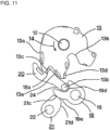
- pawl lever 20 moves to the latch engaging position due to the resilient force of ratchet spring 17, and as shown in FIG. 11 , pawl portion 15a of pawl lever 20 may be half-latched by engaging half latch engaging portion 13c. Even in this half latch state, ratchet restraint 21 holds ratchet member 15 at the latch engaged position, thereby prevents latch 13 from rotating in the releasing direction and avoids unexpected opening of the vehicle door.
- pawl portion 15a can be disengaged from half latch engaging portion 13c by rotating latch 13 toward the full-latched position.
- connecting slope 13e that is formed between half latch engaging portion 13c and full latch engaging portion 13d abuts against pole lever 20. Since gap 24 is formed between pole lever 20 and bifurcated portion 19d, pole lever 20 is then independently pushed out in the latch releasing direction, without rotating base lever 19, due to contact with connecting slope 13e. As a result, pawl portion 15a is disengaged from half latch engaging portion 13c.
- half latch engaging portion 13c and half latch engaging portion 13d can be arranged on the outer circumference of latch 13.
- cam biasing spring 23 may be omitted.
- the power release mechanism After rotating ratchet restraint 21 from the block position to the release position, the power release mechanism returns ratchet restraint 21 from the release position to the block position.
- rotational position control such as a limit switch or a contact stopper, or time-controlled rotational position control.
- the power release mechanism it is also possible to rotate ratchet restraint 21 360 degrees from the block position and to stop ratchet restraint 21 again at the block position. This configuration is advantageous in terms of both the structural and control aspects because the rotation is limited to one direction.
- ratchet restraint 21 In the case of rotating ratchet restraint 21 360 degrees, in addition to inclined cam surface 21d that is detached from base lever 19 to allow base lever 19 to move to the non-restricted position, ratchet restraint 21 has an additional inclined cam surface that pushes base lever 19 back to the restricted position.
- FIG. 12 An embodiment in which ratchet restraint 21 is connected to door key cylinder 25 is shown in FIG. 12 .
- arc-shaped slot 21e is formed in plastic cover 21b of ratchet restraint 21, and slot 21e is connected to pivoting link 26 of door key cylinders 25 via rod 27.
- Rod 27 is positioned at an intermediate part of slot 21e in the longitudinal direction thereof to provide a predetermined space on both sides. This enables ratchet restraint 21 to rotate between the block position and the release position without being affected by door key cylinder 25.
- door key cylinder 25 to rotate pivoting link 26 from the neutral position in the releasing direction or in the returning direction and then to rotate pivoting link 26 back to the neutral position, it is possible to move ratchet restraint 21 to the release position or to the block position, respectively.
- ratchet restraint 21 be coupled both to the power release mechanism and to door key cylinder 25. By doing so, even if the power release mechanism becomes inoperable during operation, it is possible to rotate door key cylinder 25 in the releasing direction to move ratchet restraint 21 to the release position, thereby to move ratchet member 15 to the latch releasing position, and thereby to release latch 13 to make the vehicle door openable. In addition, since ratchet restraint 21 can be returned to the block position, which is the initial position, by rotating back door key cylinder 25 after the vehicle door is opened, the vehicle door can be stably closed next time.
- the friction force between ratchet member 15 and ratchet restraint 21, which is generated when ratchet restraint 21 is rotated from the block position in FIG. 2 to the release position, can be effectively reduced, as compared to a conventional apparatus, and further reduction in the release operation force for rotating ratchet 21 can be expected.
- the latch returning force for latch 13 is transmitted as external force P1 from the contact point between full latch engaging portion 13d and pawl portion 15a to connecting shaft 15b, and is then transmitted as external force P2 from connecting shaft 15b to ratchet shaft 16. These external forces P1 and P2 are separated into main component force F1 and release component force F2.
- Pawl portion 15a may engage full latch engaging portion 13d either at a deep position or at a shallow position. Therefore, in a strict sense, the contact point of pawl portion 15a is different each time. Such variation of the contact point leads to the variation of the direction and the strength of external force P1 that is transmitted to connecting shaft 15b. The same applies to the direction of external force P2. As a result, main component force F1 and release component force F2 are variable.
- pawl portion 15a of the present embodiment is formed as an arc surface whose center is positioned at connecting shaft 15b.
- external force P1 always acts on the axial center of connecting shaft 15b.
- main component force F1 and release component force F2 can be prevented. Since release component force F2 becomes constant, the contact pressure between ratchet restraint 21 and ratchet member 15 becomes constant, and the release operation force of ratchet restraint 21 stably acts on ratchet member 15.
- the latch returning force is transmitted to ratchet member 15 both from full latch engaging portion 13d and from half latch engaging portion 13c.
Landscapes
- Lock And Its Accessories (AREA)
Description
- This application claims priority from
Japanese Patent Application No. 2017-248491 filed on Dec. 25, 2017 - The present invention relates to a vehicle door latch apparatus. In particular, the present invention relates to a vehicle door latch apparatus that reduces release operation force that is required to disengage a ratchet from a latch.
- In a typical prior art vehicle door latch apparatus, a ratchet engages a latch that has rotated from an unlatched position to a full-latched position, and thereby prevents the latch from rotating in a releasing direction in order to keep the vehicle door closed (in the full-latched state). Further, in the vehicle door latch apparatus, the ratchet is rotated in the latch releasing direction (a direction opposite to the latch engaging direction), by a manual release operation force from a door opening handle or by an electric release operation force from a power release mechanism, to disengage the ratchet from the latch, and thereby allows the latch to rotate in the releasing direction to make the vehicle door openable.
- The latch is strongly pressed against the ratchet in the full-latched state by being strongly biased in the releasing direction by the resilient force of a latch spring and by the repulsive force of a seal member that is provided between the door and the vehicle body. The ratchet is also biased in the latch engaging direction by the resilient force of a ratchet spring. The friction force, which is generated by the latch being pressed against ratchet, and the elasticity of the ratchet spring act as resistive force against the release operation force, resulting in degradation of the operation feeling when operating the door opening handle and in an increase in the size of the power release mechanism.
- Patent Document 1 discloses a vehicle door latch apparatus that reduces the release operation force for releasing a ratchet from a latch.
FIG. 13 shows the mechanism for reducing the release operation force in Patent Document 1. Latch A is held in the full-latched position by engagement with ratchet B, and ratchet B is prevented from rotating in the latch releasing direction by abutting against ratchet restraint C that is provided on the side of ratchet B. In the full-latched state shown inFIG. 13 , the pressure that is transmitted from latch A to ratchet B is largely supported by ratchet shaft D of ratchet B, but part of the pressure acts on ratchet B as release component force E that rotates ratchet B in the latch releasing direction. - Release component force E is set to be higher than the engagement keeping force that keeps ratchet B engaged with latch A, specifically, the sum of the friction force that is generated between latch A and ratchet B and the resilient force of the ratchet spring that biases ratchet B in the latch engaging direction. Therefore, when ratchet restraint C is rotated clockwise by the manual release operation force or by the electric release operation force in order to disengage ratchet restraint C from ratchet B, ratchet B is rotated in the latch releasing direction by release component force E and is pushed out from the latch engaging position to a latch disengaging position. As a result, ratchet B is disengaged from latch A, and the door is made openable.
- In the configuration disclosed in Patent Document 1, the friction force that is generated between ratchet restraint C and ratchet B acts as force that is resistive against the release operation force. However, the resistive force is considerably reduced as compared to the force that is resistive against the release operation force in a conventional apparatus, that is, the friction force that is generated by the latch pressing the ratchet and the resistive force that arises from the elasticity of the ratchet spring, and accordingly, the release operation force can be reduced considerably.
-
- Patent Document 1:
DE102007045228A1 - Patent Document 2:
US 2014/0621 00A1 discloses a latch device that includes: a base plate; an open lever rotatably attached to the base plate; a biasing unit that biases the open lever; and an electric release unit to be installed in an electric release type latch device in which the open lever is operated by power and a manual release unit to be installed in a manual release type latch device in which the open lever is manually operated are capable of being selectively installed in the base plate. The open lever includes an action end portion to press a ratchet engaged with a latch and disengaging the ratchet from the latch. The biasing unit biases the open lever. The manual release unit is provided with a manual release stopping unit to abut against a driven portion. - Patent Document 3:
DE 10 2009029023A1 - In the configuration of
FIG. 13 , ratchet B cannot rotate in the latch releasing direction unless ratchet restraint C is rotated clockwise by the manual release operation force or by the electric release operation force in order to disengage ratchet restraint C from ratchet B. Due to this structural limitation, latch A can only be provided with one engaging portion F that engages ratchet B. - Here, suppose that another engaging portion, specifically, a half latch engaging portion is arranged together with engaging portion F. Per this assumption, when ratchet B engages the half latch engaging portion, ratchet B, which is held by ratchet restraint C such that it cannot be disengaged from the latch, is mechanically locked by the half latch engaging portion. Therefore, the mechanically locked state of ratchet B cannot be released by a normal operation, and it is necessary to rotate ratchet restraint C by the manual release operation force or by the electric release operation force. This makes it difficult to use a typical latch that has a half latch engaging portion and a full latch engaging portion that are arranged on the outer circumference thereof.
- The present invention provides a vehicle door latch apparatus as defined in the appended independent claims. Optional features are defined in the appended dependent claims.
- A vehicle door latch apparatus according to a first aspect of the disclosure comprises:
- a latch that is engaged with a striker and that is rotatable from an unlatched position to a full-latched over rotating position;
- a ratchet member that is rotatably supported by a ratchet shaft and that has a pawl portion, wherein the pawl portion is movable between a latch engaging position, where the pawl portion can face a half latch engaging portion of the latch, and a latch releasing position, where the pawl portion is not in contact with the half latch engaging portion, wherein release component force is generated in a latch releasing direction when latch return force is applied in a releasing direction at the latch engaging position, and the ratchet member is pushed out from the latch engaging position to the latch releasing position by the release component force;
- a ratchet restraint that is arranged on a side of the ratchet member and that can be moved about a pin between a block position and a release position, wherein at the block position, the ratchet restraint abuts against the ratchet member to prevent the ratchet member from moving from a latch engaging position, where the ratchet member engages the latch due to the release component force, to a latch disengaging position, and at the release position, the ratchet restraint is detached from the latch member to allow the latch member to move from the latch engaging position to the latch disengaging position,
- the ratchet restraint has a pole lever, wherein the pole lever can be disengaged from the full latch engaging portion by rotating about a connecting shaft in a latch disengaging direction when the ratchet restraint is at the block position, and
- the ratchet member has a base lever that is rotatably supported by a ratchet shaft, and the pole lever is rotatably supported on the base lever by the connecting shaft.
- According to the vehicle door latch apparatus of the second aspect of the disclosure, in the disclosure of the vehicle door latch apparatus of the first aspect, the latch has a full latch engaging portion that is arranged together with the half latch engaging portion.
- According to the vehicle door latch apparatus of the third aspect of the disclosure, in the disclosure of the vehicle door latch apparatus of the first or second aspect, the ratchet restraint has a blocking surface, which is an arc surface whose center is positioned at the pin, and an inclined cam surface that extends contiguous with the blocking surface and whose radius from the pin gradually decreases.
- According to the vehicle door latch apparatus of the fourth aspect of the disclosure, in the disclosure of the vehicle door latch apparatus of the third aspect, the pole lever is pressed against the base lever in a latch engaging direction by resilient force of a ratchet spring, a coil portion of the ratchet spring is supported by the connecting shaft, one of spring legs of the ratchet spring is engaged with ratchet shaft, and the other is engaged with the pole lever.
- According to the vehicle door latch apparatus of the fifth aspect of the disclosure, in the disclosure of the vehicle door latch apparatus of the third aspect, the base lever can be rotated from a restricted position, where the base lever is in contact with the blocking surface, to a non-restricted position by the releasing component force.
- According to the vehicle door latch apparatus of the sixth aspect of the disclosure, in the disclosure of the vehicle door latch apparatus of the fifth aspect, the ratchet restraint includes a cam biasing spring that biases the ratchet restraint from the release position toward the block position.
- According to the vehicle door latch apparatus of the seventh aspect of the disclosure, in the disclosure of the vehicle door latch apparatus of the third aspect, the inclined cam surface of the ratchet restraint returns the base lever from the unrestricted position to the restricted position when the ratchet restraint is returned to the block position from the release position by resilient force of the cam biasing spring.
- According to the vehicle door latch apparatus of the eighth aspect of the disclosure, in the disclosure of the vehicle door latch apparatus of any one of the first to seventh aspects, the ratchet restraint can be shifted from either the block position or the release position to the other by manual release operation force.
- According to the vehicle door latch apparatus of the first aspect of the present disclosure, in the configuration in which
ratchet member 15 is prevented from moving to the latch releasing position by ratchet restraint 21,pawl portion 15a ofratchet member 15 can be disengaged fromlatch 13 while holding ratchet restraint 21 at the block position. Further, according to the vehicle door latch apparatus of the first aspect of the present disclosure,pole lever 20 can be independently moved relative tobase lever 19. - According to the vehicle door latch apparatus of the second aspect of the present disclosure, half
latch engaging portion 13c and fulllatch engaging portion 13d can be arranged side by side inlatch 13. - According to the vehicle door latch apparatus of the third aspect of the present disclosure, blocking
surface 21c ensures thatratchet member 15 is prevented from moving to the latch releasing position, andratchet member 15 can be easily returned byinclined cam surface 21d. - According to the vehicle door latch apparatus of the fourth aspect of the present disclosure,
ratchet spring 17 can be rationally arranged without exerting a spring force onbase lever 19. - According to the vehicle door latch apparatus of the fifth aspect of the present disclosure,
pawl portion 15a can be easily disengaged fromlatch 13 by rotatingbase lever 19. - According to the vehicle door latch apparatus of the sixth aspect of the present disclosure,
ratchet restraint 21 can be returned to the block position, which is the initial position, bycam biasing spring 23. - According to the vehicle door latch apparatus of the seventh aspect of the present disclosure,
base lever 19 can be returned from the non-restricted position to the restricted position by the resilient force ofcam biasing spring 23. - According to the vehicle door latch apparatus of the eighth aspect of the present disclosure, since
ratchet restraint 21 can be operated by the manual releasing operation force, even if the electric operation is not available, the door opening operation and the door closing operation can still be performed. -
-
FIG. 1 is a front view of the vehicle door latch apparatus of the present embodiment showing the unlatched state (the state in which the door is open); -
FIG. 2 is a front view of the vehicle door latch apparatus of the present embodiment showing the full-latched state (the state in which the door is closed); -
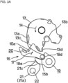
FIG. 3A is a view showing the door closing operation of the vehicle door latch apparatus of the present embodiment, wherein the latch is positioned at the half-latched position after rotation; -
FIG. 3B is a view showing the door closing operation of the vehicle door latch apparatus of the present embodiment, wherein the latch is positioned at the full-latched position after rotation; -
FIG. 3C is a view showing the door closing operation of the vehicle door latch apparatus of the present embodiment, wherein the latch is positioned at the over rotating position after rotation; -
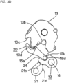
Fig. 3D is a view showing the door closing operation of the vehicle door latch apparatus of the present embodiment, wherein the latch is returned to the full-latched position and engages the ratchet member; -
FIG. 4A is a view showing the door opening operation of the vehicle door latch apparatus of the present embodiment, wherein the ratchet restraint is at an early stage of rotation in the releasing direction; -
FIG. 4B is a view showing the door opening operation of the vehicle door latch apparatus of the present embodiment, wherein the ratchet member is bent at the maximum angle, and (C) shows that the ratchet member is disengaged from the latch; -
FIG. 4C is a view showing the door opening operation of the vehicle door latch apparatus of the present embodiment, wherein the ratchet member is disengaged from the latch; -
FIG. 4D is a view showing the door opening operation of the vehicle door latch apparatus of the present embodiment, wherein the ratchet restraint is rotated at the maximum angle in the releasing direction; -
FIG. 4E is a view showing the door opening operation of the vehicle door latch apparatus of the present embodiment, wherein the ratchet restraint is returned to the block position, where the ratchet member abuts against the outer circumference of the latch; -
FIG. 5 is an exploded perspective view of the ratchet member of the present embodiment; -
FIG. 6 is a longitudinal cross-sectional view of the ratchet member of the present embodiment, wherein the ratchet spring is shown by the imaginary line; -
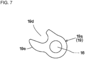
FIG. 7 is a front view of the metallic plate of the base lever of the ratchet member of the present embodiment; -
FIG. 8 is a front view of the metallic plate of the pole lever of the ratchet member of the present embodiment; -
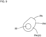
FIG. 9 is a front view of the metallic plate of the ratchet restraint of the present embodiment; -
FIG. 10 is an enlarged front view of the latch of the present embodiment; -
FIG. 11 is a front view showing the half latch state in which the pawl portion of the ratchet member is engaged with the half latch engaging portion of the latch of the present embodiment; -
FIG. 12 is a schematic diagram showing coupling means to couple the ratchet restraint to the door key cylinder in the present embodiment, and -
FIG. 13 is a view of a known example showing a conventional mechanism for reducing release operation force. - The foregoing and other objects, features and advantages of the present application will become apparent from the following detailed description with reference to the accompanying drawings that illustrate the present application.
- The present embodiment (one embodiment of the present invention) will be explained with reference to the drawings.
FIG. 1 shows the front view of vehicledoor latch apparatus 10 in the unlatched state (the state in which the door is opened).Latch 13 is rotatably supported onbase plate 11 of vehicledoor latch apparatus 10 bylatch shaft 12.Latch 13 is biased in the door opening direction (the releasing direction, or the counterclockwise direction) by latch spring 14 (shown by an arrow indicating the direction of resilience). Typically,base plate 11 is fixed to a vehicle door (not shown). -
Ratchet member 15 is rotatably supported on the lower part ofbase plate 11 byratchet shaft 16.Ratchet member 15 is biased in the latch engaging direction by ratchet spring 17 (shown by an arrow indicating the direction of resilience). In the unlatched state shown inFIG. 1 ,pawl portion 15a ofratchet member 15 is in contact withouter circumference 13a oflatch 13 due to the resilient force ofratchet spring 17. - When the vehicle door is moved in the door closing direction,
striker 18 that is fixed to the vehicle body (not shown) relatively entershorizontal striker entrance 11a that is formed inbase plate 11 to abut against U-shapedstriker engaging groove 13b oflatch 13. Striker S then rotateslatch 13 in the door closing direction (the full-latching direction, or the clockwise direction) against the resilient force oflatch spring 14. Like typical well-known latches, latch 13 has halflatch engaging portion 13c and fulllatch engaging portion 13d that are arranged on the outer circumference thereof. -
Latch 13 normally rotates from the unlatched position shown inFIG. 1 to the over rotating position shown inFIG. 3C through the half-latched position (FIG. 3A ), wherepawl portion 15a can be engaged with halflatch engaging portion 13c, and through the full-latched position (FIG. 3B ), wherepawl portion 15a can be engaged with fulllatch engaging portion 13d. InFIG. 3C ,pawl portion 15a is moved to the latch engaging position by the resilient force ofratchet spring 17. - After rotating to the over rotating position, latch 13 is returned in the releasing direction (the counterclockwise direction) by the resilient force of
latch spring 14 and by the repulsive force of a seal member (not shown) that is provided between the door and the vehicle body. Fulllatch engaging portion 13d oflatch 13 then abuts againstpawl portion 15a at the latch engaging position, as shown inFIG. 3D . The force that pushes backlatch 13 in the releasing direction is referred to hereinafter as "latch return force" or "return force". As explained above,FIGS. 3A to 3D show that the state changes in the order ofFIG. 3A ,FIG.3B ,FIG.3C andFIG.3D . In the following explanation,FIGS. 3A to 3D may be collectively referred to asFIG. 3 . - The return force that is transmitted from full
latch engaging portion 13d topawl portion 15a is largely received as main component force F1 byratchet shaft 16, as will be described later, but part of the return force is set to act as release component force F2 in a direction in whichratchet member 15 is pushed out in the latch releasing direction (the direction opposite to the latch engaging direction). - As shown in
FIGS. 5 to 8 ,ratchet member 15 of the present embodiment is divided intobase lever 19 andpole lever 20.Base lever 19 andpole lever 20 are both insert molded products each includingmetal plate resin cover Resin cover 19b is omitted inFIGS. 3A to 3D and inFIGS. 4A to 4E . Note thatFIGS. 4A to 4E show that the state changes in the order ofFIG. 4A ,FIG. 4B ,FIG. 4C ,FIG. 4D andFIG. 4E . In the following explanation,FIGS. 4A to 4E may be collectively referred to asFIG. 4 . - The base portion of
base lever 19 is rotatably supported byratchet shaft 16, and the base portion ofpole lever 20 is rotatably supported on the end portion ofbase lever 19 by connectingshaft 15b. In the present embodiment, connectingshaft 15b is formed integral withpole lever 20, and connectingshaft 15b is inserted intoshaft hole 19c that is formed inresin cover 19b.Pawl portion 15a is formed inmetal plate 20a ofpole lever 20. - Bifurcated
portion 19d is formed at the end portion ofmetal plate 19a ofbase lever 19.Connecting shaft 15b ofpole lever 20 is arranged inside ofbifurcated portion 19d.Gap 24 that is formed betweenbifurcated portion 19d and pole lever 20 (seeFIG. 6 ) allowspole lever 20 to rotate relative tobase lever 19 within a predetermined rotation angle. - As shown in
FIG. 6 , ratchetspring 17 is preferably made of a torsion coil spring.Center coil portion 17a is disposed around the outer circumference of connectingshaft 15b. Onespring leg portion 17b is in contact withratchet shaft 16, and the otherspring leg portion 17c is in contact withpole lever 20. According to this spring arrangement, the resilient force ofratchet spring 17 does not substantially act onbase lever 19, and the resilient force acts exclusively onbias pole lever 20 about connectingshaft 15b in the latch engaging direction. - .
Ratchet member 15 has connectingshaft 15b that is arranged at an intermediate position in the length direction thereof and that rotataby supportsbase lever 19 andpole lever 20. Therefore, when release component force F2 is generated inratchet member 15, release component force F2 that is directed in the latch releasing direction acts exclusively on connectingshaft 15b that is positioned at the intermediate position, to bendratchet member 15 at the intermediate position, and disengagespawl portion 15a from fulllatch engaging portion 13d. Therefore, it is impossible forratchet member 15 alone to keeplatch 13 at the full-latched position. -
Ratchet restraint 21 is disposed in the vicinity of the side ofratchet member 15.Ratchet restraint 21 keepsratchet member 15 engaged withlatch 13 by preventingratchet member 15 from moving in the latch releasing direction.Ratchet restraint 21 is rotatably supported onbase plate 11 bypin 22.Ratchet restraint 21 is an insert molded product that includesmetal plate 21a andresin cover 21b.Resin cover 21b is omitted inFIGS. 3A to 3D and inFIGS. 4A to 4E . -
Metallic plate 21a ofratchet restraint 21 is formed to be a rotating cam. On the outer circumference ofmetal plate 21a, arc-shapedblocking surface 21c whose center is positioned atpin 22 andinclined cam surface 21d that extends contiguous with blockingsurface 21c are formed.Inclined cam surface 21d is a cam surface whose radius frompin 22 gradually decreases. Blockingsurface 21c andinclined cam surface 21d abut against one ofouter walls 19e ofbifurcated portion 19d ofmetal plate 19a. -
Ratchet restraint 21 is rotatable between the block position shown inFIGS. 1 to 3 and the release position shown inFIG. 4D . The block position corresponds to the initial position ofratchet restraint 21.Ratchet restraint 21 is preferably biased from the release position towards the block position by the resilient force of cam biasing spring 23 (shown by an arrow indicating the direction of resilience). Manual release operation force from the door opening handle, a door key cylinder or the like, or electric release operation force from a power release mechanism is transmitted to ratchetrestraint 21.Ratchet restraint 21 is rotated in the releasing direction from the block position to the release position by the manual or electric release operation force. - When the release operation force is not exerted, ratchet
restraint 21 is held at the block position that corresponds to the initial position by the resilient force ofcam biasing spring 23. At the block position, blockingsurface 21c ofratchet restraint 21 is located on an extension line along which connectingshaft 15b ofratchet member 15 is moved by release component force F2. - In the door closed state in
FIG. 2 ,outer wall 19e ofbase lever 19 is in contact with blockingsurface 21c at the block position. Therefore, even if the latch returning force acting onlatch 13 is transmitted topawl portion 15a ofratchet member 15 via fulllatch engaging portion 13d, and release component force F2 to push ratchet member 15 (in particular, connectingshaft 15b) in the latch releasing direction is generated inratchet member 15,outer wall 19e that is on the line of action of release component force F2 that acts on connectingshaft 15b faces and abuts against blockingsurface 21c at the block position. Therefore, connectingshaft 15b is prevented from moving in the latch releasing direction, and is held where it is positioned. As a result,ratchet member 15 is not bent at the intermediate position, maintains the engagement betweenpawl portion 15a and fulllatch engaging portion 13d, and keeps the door closed. The position whereouter wall 19e abuts against blockingsurface 21c at the block position is the restricted position ofbase lever 19. - In the door closed state in
FIG. 2 , when the manual release operation force or the electric release operation force is transmitted to ratchetrestraint 21, ratchetrestraint 21 is rotated in the releasing direction against the resilient force ofcam biasing spring 23.FIG. 4 shows in detail howratchet member 15 operates asratchet restraint 21 is rotated in the releasing direction. - When
ratchet restraint 21 is rotated in the releasing direction, blockingsurface 21c that faces and that is in contact withouter wall 19e moves out of the line of action of release component force F2 that acts on connectingshaft 15b. Then, base lever 19 (metallic plate 19a) rotates in the latch releasing direction such that it can move from the restricted position to the unrestricted position and such that connectingshaft 15b can move in the latch releasing direction along releasing component force F2. As a result,ratchet member 15 is bent at the intermediate position.Pawl portion 15a is flipped out of fulllatch engaging portion 13d in the latch releasing direction, and, as shown inFIG. 4D ,latch 13 rotates in the releasing direction to open the door. The non-restricted position ofbase lever 19 is a position where connectingshaft 15b is moved in the latch releasing direction and whereratchet member 15 is bent at the intermediate position. - After
latch 13 is rotated in the latch releasing direction, the manual release operation force or the electric release operation force acting onratchet restraint 21 is disconnected. Then, ratchetrestraint 21 is rotated in the direction opposite to the latch releasing direction back to the block position by the resilient force ofcam biasing spring 23.Inclined cam surface 21d that is rotated in the direction opposite to the releasing direction then pressesouter wall 19e to returnbase lever 19 from the non-restricted position to the restricted position by pushingbase lever 19 in the latch engaging direction. As shown inFIG. 4E ,pawl portion 15a ofratchet member 15 then abuts againstouter circumference 13a oflatch 13 in order to restore the unlatched state shown inFIG. 1 . - In the door opened state shown in
FIG. 1 ,outer wall 19e ofbase lever 19 is in contact with blockingsurface 21c at the block position. Further,outer wall 19e continues to be in contact with blockingsurface 21c untillatch 13 reaches the over rotating position shown inFIG. 3D . In the meantime,pole lever 20 is independently movable in the latch engaging direction due togap 24 that is formed betweenpole lever 20 andbifurcated portion 19d. Therefore,pole lever 20 is movable to the latch engaging position due to the resilient force ofratchet spring 17 even in the state shown inFIGS. 3A and3B . - When
latch 13 is at the half-latched position shown inFIG. 3A ,pawl lever 20 moves to the latch engaging position due to the resilient force ofratchet spring 17, and as shown inFIG. 11 ,pawl portion 15a ofpawl lever 20 may be half-latched by engaging halflatch engaging portion 13c. Even in this half latch state, ratchetrestraint 21 holdsratchet member 15 at the latch engaged position, thereby preventslatch 13 from rotating in the releasing direction and avoids unexpected opening of the vehicle door. - In the half latch state,
pawl portion 15a can be disengaged from halflatch engaging portion 13c by rotatinglatch 13 toward the full-latched position. By pushing outlatch 13 toward the full-latched position, connectingslope 13e that is formed between halflatch engaging portion 13c and fulllatch engaging portion 13d abuts againstpole lever 20. Sincegap 24 is formed betweenpole lever 20 andbifurcated portion 19d,pole lever 20 is then independently pushed out in the latch releasing direction, without rotatingbase lever 19, due to contact with connectingslope 13e. As a result,pawl portion 15a is disengaged from halflatch engaging portion 13c. - Therefore, in the configuration in which
ratchet restraint 21 preventsratchet member 15 from moving in the latch releasing direction, halflatch engaging portion 13c and halflatch engaging portion 13d can be arranged on the outer circumference oflatch 13. - When
ratchet restraint 21 is mainly rotated by the power release mechanism,cam biasing spring 23 may be omitted. In this case, after rotatingratchet restraint 21 from the block position to the release position, the power release mechanism returns ratchetrestraint 21 from the release position to the block position. In this control operation, it is possible to use rotational position control, such as a limit switch or a contact stopper, or time-controlled rotational position control. When the power release mechanism is used, it is also possible to rotateratchet restraint 21 360 degrees from the block position and to stopratchet restraint 21 again at the block position. This configuration is advantageous in terms of both the structural and control aspects because the rotation is limited to one direction. In the case ofrotating ratchet restraint 21 360 degrees, in addition toinclined cam surface 21d that is detached frombase lever 19 to allowbase lever 19 to move to the non-restricted position, ratchetrestraint 21 has an additional inclined cam surface that pushesbase lever 19 back to the restricted position. - An embodiment in which
ratchet restraint 21 is connected to doorkey cylinder 25 is shown inFIG. 12 . As shown inFIG. 12 , arc-shapedslot 21e is formed inplastic cover 21b ofratchet restraint 21, andslot 21e is connected to pivotinglink 26 of doorkey cylinders 25 viarod 27.Rod 27 is positioned at an intermediate part ofslot 21e in the longitudinal direction thereof to provide a predetermined space on both sides. This enables ratchetrestraint 21 to rotate between the block position and the release position without being affected by doorkey cylinder 25. Further, by using doorkey cylinder 25 to rotate pivotinglink 26 from the neutral position in the releasing direction or in the returning direction and then to rotate pivotinglink 26 back to the neutral position, it is possible to moveratchet restraint 21 to the release position or to the block position, respectively. - Since electrical components, such as a power release mechanism that is coupled to ratchet
restraint 21, cannot be completely free of electrical problems, it is desirable thatratchet restraint 21 be coupled both to the power release mechanism and to doorkey cylinder 25. By doing so, even if the power release mechanism becomes inoperable during operation, it is possible to rotate doorkey cylinder 25 in the releasing direction to moveratchet restraint 21 to the release position, thereby to moveratchet member 15 to the latch releasing position, and thereby to releaselatch 13 to make the vehicle door openable. In addition, sinceratchet restraint 21 can be returned to the block position, which is the initial position, by rotating back doorkey cylinder 25 after the vehicle door is opened, the vehicle door can be stably closed next time. - In the above description, the friction force between
ratchet member 15 and ratchetrestraint 21, which is generated whenratchet restraint 21 is rotated from the block position inFIG. 2 to the release position, can be effectively reduced, as compared to a conventional apparatus, and further reduction in the release operation force for rotatingratchet 21 can be expected. - The latch returning force for
latch 13 is transmitted as external force P1 from the contact point between fulllatch engaging portion 13d andpawl portion 15a to connectingshaft 15b, and is then transmitted as external force P2 from connectingshaft 15b to ratchetshaft 16. These external forces P1 and P2 are separated into main component force F1 and release component force F2. -
Pawl portion 15a may engage fulllatch engaging portion 13d either at a deep position or at a shallow position. Therefore, in a strict sense, the contact point ofpawl portion 15a is different each time. Such variation of the contact point leads to the variation of the direction and the strength of external force P1 that is transmitted to connectingshaft 15b. The same applies to the direction of external force P2. As a result, main component force F1 and release component force F2 are variable. - In order to avoid such variation,
pawl portion 15a of the present embodiment is formed as an arc surface whose center is positioned at connectingshaft 15b. By forming pawl portion 15a as an arc surface, even if the position wherepawl portion 15a engages fulllatch engaging portion 13d is shifted, external force P1 always acts on the axial center of connectingshaft 15b. As a result, the direction and the strength of external force P1 is stabilized, and a change in external force P2, main component force F1 and release component force F2 can be prevented. Since release component force F2 becomes constant, the contact pressure betweenratchet restraint 21 and ratchetmember 15 becomes constant, and the release operation force ofratchet restraint 21 stably acts onratchet member 15. - The latch returning force is transmitted to ratchet
member 15 both from fulllatch engaging portion 13d and from halflatch engaging portion 13c. Although some part of the above explanation only refers to the relationship between fulllatch engaging portion 13d andpawl portion 15a, the same applies to the relationship between halflatch engaging portion 13c andpawl portion 15a. -
- 10
- Vehicle door latch apparatus
- 11
- Base plate
- 11a
- Striker entrance
- 12
- Latch shaft
- 13
- Latch
- 13a
- Outer circumference
- 13b
- Striker engaging groove
- 13c
- Half latch engaging portion
- 13d
- Full latch engaging portion
- 13e
- Connecting slope
- 14
- Latch spring
- 15
- Ratchet member
- 15a
- Pawl portion
- 15b
- Connecting shaft
- 16
- Ratchet shaft
- 17
- Ratchet spring
- 17a
- Coil portion
- 17b
- Spring leg portion
- 17c
- Spring leg portion
- 18
- Striker
- 19
- Base lever
- 19a
- Metal plate
- 19b
- Resin cover
- 19c
- Shaft hole
- 19d
- Bifurcated portion
- 19e
- Outer wall
- 20
- Pole lever
- 20a
- Metal plate
- 20b
- Resin cover
- 21
- Ratchet restraint
- 21a
- Metal plate
- 21b
- Resin cover
- 21c
- Blocking surface
- 21d
- Inclined cam surface
- 21e
- Slot
- 22
- Pin
- 23
- Cam biasing spring
- 24
- Gap
- 25
- Door key cylinder
- 26
- Pivoting link
- 27
- Rod
- F1
- Main component force
- F2
- Release component force
- P1
- External force
- P2
- External force
Claims (8)
- A vehicle door latch apparatus (10) comprising:a latch (13) that is engaged with a striker (18) and that is rotatable from an unlatched position to an over rotating position;a ratchet member (15) that is rotatably supported by a ratchet shaft (16) and that has a pawl portion (15a), wherein the pawl portion (15a) is movable between a latch engaging position, where the pawl portion (15a) can face a half latch engaging portion (13c) of the latch (13), and a latch releasing position, where the pawl portion (15a) is not in contact with the half latch engaging portion (13c), wherein release component force is generated in a latch releasing direction when latch return force is applied in a releasing direction at the latch engaging position, and the ratchet member (15) is pushed out from the latch engaging position to the latch releasing position by the release component force;a ratchet restraint (21) that is arranged on a side of the ratchet member (15) and that can be moved about a pin (22) between a block position and a release position, wherein at the block position, the ratchet restraint (21) abuts against the ratchet member (15) to prevent the pawl portion (15a) of the ratchet member (15) from moving from the latch engaging position to the latch releasing position due to the release component force, and at the release position, the ratchet restraint (21) is detached from the ratchet member (15) to allow the pawl portion (15a) of the ratchet member (15) to move from the latch engaging position to the latch releasing position,the ratchet member (15) has a pole lever (20) having the pawl portion (15a), wherein the pole lever (20) can be disengaged from the half latch engaging portion (13c) by rotating about a connecting shaft (15b) in a latch disengaging direction when the ratchet restraint (21) is at the block position, andthe ratchet member (15) has a base lever (19) that is rotatably supported by the ratchet shaft (16), and the pole lever (20) is rotatably supported on the base lever (19) by the connecting shaft (15b),characterized in that the base lever (19) includes a bifurcated portion (19d), and the connecting shaft (15b) is arranged inside of the bifurcated portion (19d) such that a gap (24) is formed between the bifurcated portion (19d) and the pole lever (20), wherein the gap (24) allows the pole lever (20) to rotate relative to the base lever (19) within a predetermined rotation angle.
- The vehicle door latch apparatus (10) according to claim 1, wherein the latch (13) has a full latch engaging portion (13d) that is arranged together with the half latch engaging portion (13c) on an outer circumference of the latch (13a).
- The vehicle door latch apparatus (10) according to claim 1 or 2, wherein the ratchet restraint (21) has a blocking surface (21c), which is an arc surface whose center is positioned at the pin (22), and an inclined cam surface (21d) that extends contiguous with the blocking surface (21c) and whose radius from the pin (22) gradually decreases.
- The vehicle door latch apparatus (10) according to claim 3, wherein the pole lever (20) is pressed against the base lever in a latch engaging direction by resilient force of a ratchet spring (17), a coil portion (17a) of the ratchet spring (17) is supported by the connecting shaft (15b), one of spring legs (17b, 17c) of the ratchet spring (17) is engaged with the ratchet shaft (16), and the other is engaged with the pole lever (20).
- The vehicle door latch apparatus (10) according to claim 3, wherein the base lever (19) can be rotated from a restricted position, where the base lever (19) is in contact with the blocking surface (21c), to a non-restricted position by the releasing component force.
- The vehicle door latch apparatus (10) according to claim 5, wherein the ratchet restraint (21) includes a cam biasing spring (23) that biases the ratchet restraint (21) from the release position toward the block position.
- The vehicle door latch apparatus (10) according to claim 6, wherein the inclined cam surface (21d) of the ratchet restraint (21) returns the base lever (19) from the non-restricted position to the restricted position when the ratchet restraint (21) is returned to the block position from the release position by resilient force of the cam biasing spring (23).
- The vehicle door latch apparatus (10) according to any one of claims 1 to 3 and 4 to 7, wherein the ratchet restraint (21) can be shifted from either the block position or the release position to the other by manual release operation force.
Applications Claiming Priority (2)
| Application Number | Priority Date | Filing Date | Title |
|---|---|---|---|
| JP2017248491A JP6884094B2 (en) | 2017-12-25 | 2017-12-25 | Vehicle door latch device |
| PCT/JP2018/010866 WO2019130607A1 (en) | 2017-12-25 | 2018-03-19 | Vehicle door latch device |
Publications (3)
| Publication Number | Publication Date |
|---|---|
| EP3734004A1 EP3734004A1 (en) | 2020-11-04 |
| EP3734004A4 EP3734004A4 (en) | 2021-09-08 |
| EP3734004B1 true EP3734004B1 (en) | 2025-01-08 |
Family
ID=67066800
Family Applications (1)
| Application Number | Title | Priority Date | Filing Date |
|---|---|---|---|
| EP18893757.7A Active EP3734004B1 (en) | 2017-12-25 | 2018-03-19 | Vehicle door latch device |
Country Status (5)
| Country | Link |
|---|---|
| US (1) | US11674341B2 (en) |
| EP (1) | EP3734004B1 (en) |
| JP (2) | JP6884094B2 (en) |
| CN (1) | CN111566299B (en) |
| WO (1) | WO2019130607A1 (en) |
Families Citing this family (12)
| Publication number | Priority date | Publication date | Assignee | Title |
|---|---|---|---|---|
| JP6884094B2 (en) | 2017-12-25 | 2021-06-09 | 三井金属アクト株式会社 | Vehicle door latch device |
| WO2019130618A1 (en) | 2017-12-25 | 2019-07-04 | 三井金属アクト株式会社 | Vehicle door latch device |
| DE102019105631A1 (en) * | 2019-03-06 | 2020-09-10 | Kiekert Aktiengesellschaft | Motor vehicle lock |
| DE102019107229A1 (en) * | 2019-03-21 | 2020-09-24 | Kiekert Aktiengesellschaft | Door lock, in particular motor vehicle door lock |
| FR3102498B1 (en) * | 2019-10-29 | 2021-12-10 | U Shin France | Motor vehicle door lock |
| JP7283015B2 (en) * | 2019-11-12 | 2023-05-30 | 三井金属アクト株式会社 | door latch device |
| JP7443951B2 (en) * | 2020-06-19 | 2024-03-06 | 三井金属アクト株式会社 | Vehicle door latch device |
| DE102021102105A1 (en) * | 2021-01-29 | 2022-08-04 | Brose Schließsysteme GmbH & Co. Kommanditgesellschaft | motor vehicle lock |
| DE102021123441A1 (en) * | 2021-09-10 | 2023-03-16 | Kiekert Aktiengesellschaft | Motor vehicle lock, in particular motor vehicle door lock |
| JP7795698B2 (en) * | 2022-03-03 | 2026-01-08 | 株式会社ハイレックスアクト | Vehicle door latch device |
| CN115992627B (en) * | 2023-02-28 | 2024-12-13 | 麦格纳汽车系统(苏州)有限公司 | Door locks and vehicles |
| KR102971872B1 (en) * | 2024-04-19 | 2026-06-04 | 피에이치에이 주식회사 | Latch apparatus for vehicle |
Family Cites Families (28)
| Publication number | Priority date | Publication date | Assignee | Title |
|---|---|---|---|---|
| IT217128Z2 (en) * | 1989-07-04 | 1991-11-12 | Fiat Auto Spa | LOCK WITH REDUCED OPENING LOAD |
| DE4102049A1 (en) * | 1991-01-24 | 1992-07-30 | Kiekert Gmbh Co Kg | MOTOR VEHICLE DOOR LOCK |
| DE19913666B4 (en) * | 1999-03-25 | 2010-08-05 | Witte-Velbert Gmbh & Co. Kg | Motor-openable rotary latch closure, especially for tailgates of motor vehicles |
| RU2398948C2 (en) | 2005-02-18 | 2010-09-10 | Меритор Текнолоджи, Инк. | Latch |
| DE102007003948A1 (en) * | 2006-11-22 | 2008-05-29 | Kiekert Ag | Locking unit with multipart pawl |
| FR2916788B1 (en) * | 2007-06-01 | 2013-02-15 | Valeo Securite Habitacle | ELECTRIC LOCK WITH CLOSURE ASSIST FOR OPENING OF A MOTOR VEHICLE |
| DE102007045228A1 (en) | 2007-09-21 | 2008-02-28 | Daimler Ag | Vehicle door lock has rotary latch, which clutches locking bolt during closing of vehicle door, where rotary latch is lockable in closed condition of the vehicle door of locking device |
| EP2310601B1 (en) * | 2008-05-26 | 2016-02-24 | Magna Closures SpA | Double pawl vehicle latch |
| US8596694B2 (en) * | 2008-09-04 | 2013-12-03 | Magna Closures S.P.A. | Vehicle latch with secondary engagement between cam and auxiliary pawl |
| CA2697768A1 (en) | 2009-03-25 | 2010-09-25 | Magna Closures Inc. | Closure latch for vehicle door |
| US8235428B2 (en) * | 2009-07-14 | 2012-08-07 | Kiekert Ag | Lock unit having a slotted pawl |
| DE102009029041B4 (en) | 2009-08-31 | 2017-08-24 | Kiekert Ag | Motor vehicle lock |
| DE102009029023A1 (en) | 2009-08-31 | 2011-03-03 | Kiekert Ag | Lock for motor vehicle, has locking gear comprising rotary latch for retaining closing pin and ratchet pawl, where ratchet pawl is provided with rotatably mounted carrier handle and closing handle that is connected by joint |
| EP3567196A1 (en) * | 2010-02-05 | 2019-11-13 | Magna Closures SpA | Vehicular latch with double pawl arrangement |
| BR112012020794B1 (en) * | 2010-02-19 | 2019-08-20 | Aisin Seiki Kabushiki Kaisha | AUTOMOTIVE DOOR LOCK DEVICE |
| JP5614332B2 (en) * | 2011-02-28 | 2014-10-29 | アイシン精機株式会社 | Vehicle locking device |
| DE202011003497U1 (en) | 2011-03-04 | 2012-06-05 | Kiekert Ag | Motor vehicle door lock |
| DE112012002272T5 (en) * | 2011-05-27 | 2014-03-13 | Magna Closures S.P.A. | Double rotary latch and double pawl vehicle lock with reset soft stop |
| US9309699B2 (en) | 2012-08-28 | 2016-04-12 | Mitsui Kinzoku Act Corporation | Latch device |
| JP6069763B2 (en) | 2013-04-25 | 2017-02-01 | 株式会社ホンダロック | Latch control device for vehicle door |
| ITTO20130781A1 (en) * | 2013-09-30 | 2015-03-31 | Magna Closures Spa | LOCK FOR A DOOR OF A MOTOR VEHICLE |
| KR101434980B1 (en) * | 2013-10-08 | 2014-08-27 | 평화정공(주) | Latch apparatus |
| EP3260635B1 (en) | 2015-02-17 | 2019-10-16 | Gecom Corporation | Automobile door latch apparatus |
| DE102016218299A1 (en) * | 2015-09-29 | 2017-03-30 | Magna Closures S.P.A. | One-motor locking arrangement with power-tightening and power-unlocking with a soft opening function |
| JP6665384B2 (en) | 2016-06-15 | 2020-03-13 | 三井金属アクト株式会社 | Latch device for vehicle back door |
| DE102017124517A1 (en) | 2017-10-20 | 2019-04-25 | Kiekert Ag | Motor vehicle locking system with electrical opening device |
| JP6884094B2 (en) | 2017-12-25 | 2021-06-09 | 三井金属アクト株式会社 | Vehicle door latch device |
| JP6777679B2 (en) | 2018-04-18 | 2020-10-28 | 三井金属アクト株式会社 | Vehicle door latch device |
-
2017
- 2017-12-25 JP JP2017248491A patent/JP6884094B2/en active Active
-
2018
- 2018-03-19 CN CN201880083926.8A patent/CN111566299B/en active Active
- 2018-03-19 US US16/761,705 patent/US11674341B2/en active Active
- 2018-03-19 EP EP18893757.7A patent/EP3734004B1/en active Active
- 2018-03-19 WO PCT/JP2018/010866 patent/WO2019130607A1/en not_active Ceased
-
2021
- 2021-05-07 JP JP2021079277A patent/JP7036356B2/en active Active
Also Published As
| Publication number | Publication date |
|---|---|
| EP3734004A4 (en) | 2021-09-08 |
| JP2021119290A (en) | 2021-08-12 |
| JP7036356B2 (en) | 2022-03-15 |
| US11674341B2 (en) | 2023-06-13 |
| EP3734004A1 (en) | 2020-11-04 |
| JP2019112875A (en) | 2019-07-11 |
| US20210180372A1 (en) | 2021-06-17 |
| JP6884094B2 (en) | 2021-06-09 |
| WO2019130607A1 (en) | 2019-07-04 |
| CN111566299A (en) | 2020-08-21 |
| CN111566299B (en) | 2021-10-22 |
Similar Documents
| Publication | Publication Date | Title |
|---|---|---|
| EP3734004A1 (en) | Vehicle door latch device | |
| US8789861B2 (en) | Vehicle door operating mechanism | |
| EP2130715B1 (en) | Locking device | |
| US11555337B2 (en) | Vehicle door latch apparatus | |
| CN102057119B (en) | Door lock device | |
| US11608664B2 (en) | Vehicle door latch apparatus | |
| CN103703200A (en) | Lock device for opening/closing member | |
| JP7127242B2 (en) | Automotive door latch device | |
| GB2337295A (en) | Anti-panic vehicle door latch device | |
| US12270228B2 (en) | Catch mechanism for a locking device | |
| CN107542334B (en) | Door lock device | |
| KR101806612B1 (en) | vehicle door latch for preventing locking | |
| JP6186604B2 (en) | Flap or door lock | |
| KR100535053B1 (en) | Door latch for automobile | |
| CN109653616B (en) | vehicle door lock | |
| JP5602369B2 (en) | Cylinder lock | |
| JP5420950B2 (en) | Vehicle door handle device | |
| US20250179842A1 (en) | Lock device of opened back door for vehicle | |
| US20190119961A1 (en) | Vehicle door lock device | |
| JPH11141207A (en) | Latch lock | |
| CN220382025U (en) | Closing holding mechanism for electrical switches and electrical switches | |
| CN110306882A (en) | door lock | |
| JP6089299B2 (en) | Door latch device for automobile | |
| JP2019167755A (en) | Latch device for vehicle door | |
| AU2018317489B2 (en) | A lock assembly |
Legal Events
| Date | Code | Title | Description |
|---|---|---|---|
| STAA | Information on the status of an ep patent application or granted ep patent |
Free format text: STATUS: THE INTERNATIONAL PUBLICATION HAS BEEN MADE |
|
| PUAI | Public reference made under article 153(3) epc to a published international application that has entered the european phase |
Free format text: ORIGINAL CODE: 0009012 |
|
| STAA | Information on the status of an ep patent application or granted ep patent |
Free format text: STATUS: REQUEST FOR EXAMINATION WAS MADE |
|
| 17P | Request for examination filed |
Effective date: 20200713 |
|
| AK | Designated contracting states |
Kind code of ref document: A1 Designated state(s): AL AT BE BG CH CY CZ DE DK EE ES FI FR GB GR HR HU IE IS IT LI LT LU LV MC MK MT NL NO PL PT RO RS SE SI SK SM TR |
|
| AX | Request for extension of the european patent |
Extension state: BA ME |
|
| DAV | Request for validation of the european patent (deleted) | ||
| DAX | Request for extension of the european patent (deleted) | ||
| A4 | Supplementary search report drawn up and despatched |
Effective date: 20210810 |
|
| RIC1 | Information provided on ipc code assigned before grant |
Ipc: E05B 81/42 20140101ALI20210804BHEP Ipc: E05B 81/14 20140101ALI20210804BHEP Ipc: E05B 85/26 20140101AFI20210804BHEP |
|
| RIN1 | Information on inventor provided before grant (corrected) |
Inventor name: KABURAKI, MAKOTO Inventor name: OKAWA, SHINTARO Inventor name: KAKUMAE, TAKUYA Inventor name: NISHIJIMA, HIROTAKA Inventor name: ISHIGURO, KATSUYUKI |
|
| GRAP | Despatch of communication of intention to grant a patent |
Free format text: ORIGINAL CODE: EPIDOSNIGR1 |
|
| STAA | Information on the status of an ep patent application or granted ep patent |
Free format text: STATUS: GRANT OF PATENT IS INTENDED |
|
| INTG | Intention to grant announced |
Effective date: 20240816 |
|
| GRAS | Grant fee paid |
Free format text: ORIGINAL CODE: EPIDOSNIGR3 |
|
| GRAA | (expected) grant |
Free format text: ORIGINAL CODE: 0009210 |
|
| STAA | Information on the status of an ep patent application or granted ep patent |
Free format text: STATUS: THE PATENT HAS BEEN GRANTED |
|
| AK | Designated contracting states |
Kind code of ref document: B1 Designated state(s): AL AT BE BG CH CY CZ DE DK EE ES FI FR GB GR HR HU IE IS IT LI LT LU LV MC MK MT NL NO PL PT RO RS SE SI SK SM TR |
|
| REG | Reference to a national code |
Ref country code: GB Ref legal event code: FG4D |
|
| P01 | Opt-out of the competence of the unified patent court (upc) registered |
Free format text: CASE NUMBER: APP_64391/2024 Effective date: 20241204 |
|
| REG | Reference to a national code |
Ref country code: CH Ref legal event code: EP |
|
| REG | Reference to a national code |
Ref country code: DE Ref legal event code: R096 Ref document number: 602018078443 Country of ref document: DE |
|
| REG | Reference to a national code |
Ref country code: IE Ref legal event code: FG4D |
|
| REG | Reference to a national code |
Ref country code: LT Ref legal event code: MG9D |
|
| REG | Reference to a national code |
Ref country code: NL Ref legal event code: MP Effective date: 20250108 |
|
| REG | Reference to a national code |
Ref country code: AT Ref legal event code: MK05 Ref document number: 1758419 Country of ref document: AT Kind code of ref document: T Effective date: 20250108 |
|
| PG25 | Lapsed in a contracting state [announced via postgrant information from national office to epo] |
Ref country code: NL Free format text: LAPSE BECAUSE OF FAILURE TO SUBMIT A TRANSLATION OF THE DESCRIPTION OR TO PAY THE FEE WITHIN THE PRESCRIBED TIME-LIMIT Effective date: 20250108 |
|
| PG25 | Lapsed in a contracting state [announced via postgrant information from national office to epo] |
Ref country code: RS Free format text: LAPSE BECAUSE OF FAILURE TO SUBMIT A TRANSLATION OF THE DESCRIPTION OR TO PAY THE FEE WITHIN THE PRESCRIBED TIME-LIMIT Effective date: 20250408 |
|
| PG25 | Lapsed in a contracting state [announced via postgrant information from national office to epo] |
Ref country code: FI Free format text: LAPSE BECAUSE OF FAILURE TO SUBMIT A TRANSLATION OF THE DESCRIPTION OR TO PAY THE FEE WITHIN THE PRESCRIBED TIME-LIMIT Effective date: 20250108 |
|
| PG25 | Lapsed in a contracting state [announced via postgrant information from national office to epo] |
Ref country code: PL Free format text: LAPSE BECAUSE OF FAILURE TO SUBMIT A TRANSLATION OF THE DESCRIPTION OR TO PAY THE FEE WITHIN THE PRESCRIBED TIME-LIMIT Effective date: 20250108 |
|
| PG25 | Lapsed in a contracting state [announced via postgrant information from national office to epo] |
Ref country code: ES Free format text: LAPSE BECAUSE OF FAILURE TO SUBMIT A TRANSLATION OF THE DESCRIPTION OR TO PAY THE FEE WITHIN THE PRESCRIBED TIME-LIMIT Effective date: 20250108 |
|
| PG25 | Lapsed in a contracting state [announced via postgrant information from national office to epo] |
Ref country code: NO Free format text: LAPSE BECAUSE OF FAILURE TO SUBMIT A TRANSLATION OF THE DESCRIPTION OR TO PAY THE FEE WITHIN THE PRESCRIBED TIME-LIMIT Effective date: 20250408 Ref country code: IS Free format text: LAPSE BECAUSE OF FAILURE TO SUBMIT A TRANSLATION OF THE DESCRIPTION OR TO PAY THE FEE WITHIN THE PRESCRIBED TIME-LIMIT Effective date: 20250508 |
|
| PG25 | Lapsed in a contracting state [announced via postgrant information from national office to epo] |
Ref country code: HR Free format text: LAPSE BECAUSE OF FAILURE TO SUBMIT A TRANSLATION OF THE DESCRIPTION OR TO PAY THE FEE WITHIN THE PRESCRIBED TIME-LIMIT Effective date: 20250108 |
|
| PG25 | Lapsed in a contracting state [announced via postgrant information from national office to epo] |
Ref country code: LV Free format text: LAPSE BECAUSE OF FAILURE TO SUBMIT A TRANSLATION OF THE DESCRIPTION OR TO PAY THE FEE WITHIN THE PRESCRIBED TIME-LIMIT Effective date: 20250108 Ref country code: PT Free format text: LAPSE BECAUSE OF FAILURE TO SUBMIT A TRANSLATION OF THE DESCRIPTION OR TO PAY THE FEE WITHIN THE PRESCRIBED TIME-LIMIT Effective date: 20250508 |
|
| PG25 | Lapsed in a contracting state [announced via postgrant information from national office to epo] |
Ref country code: GR Free format text: LAPSE BECAUSE OF FAILURE TO SUBMIT A TRANSLATION OF THE DESCRIPTION OR TO PAY THE FEE WITHIN THE PRESCRIBED TIME-LIMIT Effective date: 20250409 Ref country code: BG Free format text: LAPSE BECAUSE OF FAILURE TO SUBMIT A TRANSLATION OF THE DESCRIPTION OR TO PAY THE FEE WITHIN THE PRESCRIBED TIME-LIMIT Effective date: 20250108 |
|
| PG25 | Lapsed in a contracting state [announced via postgrant information from national office to epo] |
Ref country code: AT Free format text: LAPSE BECAUSE OF FAILURE TO SUBMIT A TRANSLATION OF THE DESCRIPTION OR TO PAY THE FEE WITHIN THE PRESCRIBED TIME-LIMIT Effective date: 20250108 |
|
| PG25 | Lapsed in a contracting state [announced via postgrant information from national office to epo] |
Ref country code: SE Free format text: LAPSE BECAUSE OF FAILURE TO SUBMIT A TRANSLATION OF THE DESCRIPTION OR TO PAY THE FEE WITHIN THE PRESCRIBED TIME-LIMIT Effective date: 20250108 |
|
| REG | Reference to a national code |
Ref country code: DE Ref legal event code: R119 Ref document number: 602018078443 Country of ref document: DE |
|
| PG25 | Lapsed in a contracting state [announced via postgrant information from national office to epo] |
Ref country code: SM Free format text: LAPSE BECAUSE OF FAILURE TO SUBMIT A TRANSLATION OF THE DESCRIPTION OR TO PAY THE FEE WITHIN THE PRESCRIBED TIME-LIMIT Effective date: 20250108 |
|
| PG25 | Lapsed in a contracting state [announced via postgrant information from national office to epo] |
Ref country code: DK Free format text: LAPSE BECAUSE OF FAILURE TO SUBMIT A TRANSLATION OF THE DESCRIPTION OR TO PAY THE FEE WITHIN THE PRESCRIBED TIME-LIMIT Effective date: 20250108 |
|
| PG25 | Lapsed in a contracting state [announced via postgrant information from national office to epo] |
Ref country code: MC Free format text: LAPSE BECAUSE OF FAILURE TO SUBMIT A TRANSLATION OF THE DESCRIPTION OR TO PAY THE FEE WITHIN THE PRESCRIBED TIME-LIMIT Effective date: 20250108 |
|
| PG25 | Lapsed in a contracting state [announced via postgrant information from national office to epo] |
Ref country code: EE Free format text: LAPSE BECAUSE OF FAILURE TO SUBMIT A TRANSLATION OF THE DESCRIPTION OR TO PAY THE FEE WITHIN THE PRESCRIBED TIME-LIMIT Effective date: 20250108 Ref country code: CZ Free format text: LAPSE BECAUSE OF FAILURE TO SUBMIT A TRANSLATION OF THE DESCRIPTION OR TO PAY THE FEE WITHIN THE PRESCRIBED TIME-LIMIT Effective date: 20250108 |
|
| REG | Reference to a national code |
Ref country code: CH Ref legal event code: H13 Free format text: ST27 STATUS EVENT CODE: U-0-0-H10-H13 (AS PROVIDED BY THE NATIONAL OFFICE) Effective date: 20251023 |
|
| PG25 | Lapsed in a contracting state [announced via postgrant information from national office to epo] |
Ref country code: RO Free format text: LAPSE BECAUSE OF FAILURE TO SUBMIT A TRANSLATION OF THE DESCRIPTION OR TO PAY THE FEE WITHIN THE PRESCRIBED TIME-LIMIT Effective date: 20250108 |
|
| PG25 | Lapsed in a contracting state [announced via postgrant information from national office to epo] |
Ref country code: SK Free format text: LAPSE BECAUSE OF FAILURE TO SUBMIT A TRANSLATION OF THE DESCRIPTION OR TO PAY THE FEE WITHIN THE PRESCRIBED TIME-LIMIT Effective date: 20250108 |
|
| PLBE | No opposition filed within time limit |
Free format text: ORIGINAL CODE: 0009261 |
|
| STAA | Information on the status of an ep patent application or granted ep patent |
Free format text: STATUS: NO OPPOSITION FILED WITHIN TIME LIMIT |
|
| PG25 | Lapsed in a contracting state [announced via postgrant information from national office to epo] |
Ref country code: LU Free format text: LAPSE BECAUSE OF NON-PAYMENT OF DUE FEES Effective date: 20250319 |
|
| REG | Reference to a national code |
Ref country code: BE Ref legal event code: MM Effective date: 20250331 |
|
| 26N | No opposition filed |
Effective date: 20251009 |
|
| GBPC | Gb: european patent ceased through non-payment of renewal fee |
Effective date: 20250408 |
|
| PG25 | Lapsed in a contracting state [announced via postgrant information from national office to epo] |
Ref country code: DE Free format text: LAPSE BECAUSE OF NON-PAYMENT OF DUE FEES Effective date: 20251001 |
|
| PG25 | Lapsed in a contracting state [announced via postgrant information from national office to epo] |
Ref country code: GB Free format text: LAPSE BECAUSE OF NON-PAYMENT OF DUE FEES Effective date: 20250408 |
|
| PG25 | Lapsed in a contracting state [announced via postgrant information from national office to epo] |
Ref country code: BE Free format text: LAPSE BECAUSE OF NON-PAYMENT OF DUE FEES Effective date: 20250331 |
|
| PG25 | Lapsed in a contracting state [announced via postgrant information from national office to epo] |
Ref country code: CH Free format text: LAPSE BECAUSE OF NON-PAYMENT OF DUE FEES Effective date: 20250331 |
|
| PG25 | Lapsed in a contracting state [announced via postgrant information from national office to epo] |
Ref country code: IE Free format text: LAPSE BECAUSE OF NON-PAYMENT OF DUE FEES Effective date: 20250319 |
|
| PG25 | Lapsed in a contracting state [announced via postgrant information from national office to epo] |
Ref country code: IT Free format text: LAPSE BECAUSE OF FAILURE TO SUBMIT A TRANSLATION OF THE DESCRIPTION OR TO PAY THE FEE WITHIN THE PRESCRIBED TIME-LIMIT Effective date: 20250108 |
|
| PGFP | Annual fee paid to national office [announced via postgrant information from national office to epo] |
Ref country code: FR Payment date: 20260209 Year of fee payment: 9 |
|
| PG25 | Lapsed in a contracting state [announced via postgrant information from national office to epo] |
Ref country code: CY Free format text: LAPSE BECAUSE OF FAILURE TO SUBMIT A TRANSLATION OF THE DESCRIPTION OR TO PAY THE FEE WITHIN THE PRESCRIBED TIME-LIMIT Effective date: 20250108 |
|
| PG25 | Lapsed in a contracting state [announced via postgrant information from national office to epo] |
Ref country code: LT Free format text: LAPSE BECAUSE OF FAILURE TO SUBMIT A TRANSLATION OF THE DESCRIPTION OR TO PAY THE FEE WITHIN THE PRESCRIBED TIME-LIMIT Effective date: 20250108 |
|
| PG25 | Lapsed in a contracting state [announced via postgrant information from national office to epo] |
Ref country code: TR Free format text: LAPSE BECAUSE OF FAILURE TO SUBMIT A TRANSLATION OF THE DESCRIPTION OR TO PAY THE FEE WITHIN THE PRESCRIBED TIME-LIMIT Effective date: 20250108 |