EP3733463A1 - Spray gun and car washing machine provided with same - Google Patents
Spray gun and car washing machine provided with same Download PDFInfo
- Publication number
- EP3733463A1 EP3733463A1 EP18897749.0A EP18897749A EP3733463A1 EP 3733463 A1 EP3733463 A1 EP 3733463A1 EP 18897749 A EP18897749 A EP 18897749A EP 3733463 A1 EP3733463 A1 EP 3733463A1
- Authority
- EP
- European Patent Office
- Prior art keywords
- spray gun
- operating handle
- passage
- gas outlet
- main body
- Prior art date
- Legal status (The legal status is an assumption and is not a legal conclusion. Google has not performed a legal analysis and makes no representation as to the accuracy of the status listed.)
- Granted
Links
- 239000007921 spray Substances 0.000 title claims abstract description 154
- 238000005406 washing Methods 0.000 title description 2
- 238000007789 sealing Methods 0.000 claims abstract description 82
- 238000005192 partition Methods 0.000 claims abstract description 62
- 239000012530 fluid Substances 0.000 claims abstract description 22
- 238000004891 communication Methods 0.000 claims description 17
- 230000000694 effects Effects 0.000 description 11
- 238000003825 pressing Methods 0.000 description 8
- 230000009471 action Effects 0.000 description 4
- XLYOFNOQVPJJNP-UHFFFAOYSA-N water Substances O XLYOFNOQVPJJNP-UHFFFAOYSA-N 0.000 description 4
- 238000004140 cleaning Methods 0.000 description 2
- 230000006872 improvement Effects 0.000 description 2
- 238000012986 modification Methods 0.000 description 2
- 230000004048 modification Effects 0.000 description 2
- 230000003749 cleanliness Effects 0.000 description 1
- 238000011161 development Methods 0.000 description 1
- 238000010586 diagram Methods 0.000 description 1
- 238000001035 drying Methods 0.000 description 1
- 238000004134 energy conservation Methods 0.000 description 1
- 230000007613 environmental effect Effects 0.000 description 1
- 230000036541 health Effects 0.000 description 1
- 238000012423 maintenance Methods 0.000 description 1
- 230000007246 mechanism Effects 0.000 description 1
- 238000000034 method Methods 0.000 description 1
- 239000003973 paint Substances 0.000 description 1
- 230000008569 process Effects 0.000 description 1
- 239000002351 wastewater Substances 0.000 description 1
Images

Classifications
-
- B—PERFORMING OPERATIONS; TRANSPORTING
- B60—VEHICLES IN GENERAL
- B60S—SERVICING, CLEANING, REPAIRING, SUPPORTING, LIFTING, OR MANOEUVRING OF VEHICLES, NOT OTHERWISE PROVIDED FOR
- B60S3/00—Vehicle cleaning apparatus not integral with vehicles
- B60S3/04—Vehicle cleaning apparatus not integral with vehicles for exteriors of land vehicles
- B60S3/044—Hand-held cleaning arrangements with liquid or gas distributing means
-
- B—PERFORMING OPERATIONS; TRANSPORTING
- B60—VEHICLES IN GENERAL
- B60S—SERVICING, CLEANING, REPAIRING, SUPPORTING, LIFTING, OR MANOEUVRING OF VEHICLES, NOT OTHERWISE PROVIDED FOR
- B60S3/00—Vehicle cleaning apparatus not integral with vehicles
- B60S3/04—Vehicle cleaning apparatus not integral with vehicles for exteriors of land vehicles
- B60S3/045—Other hand-held cleaning arrangements, e.g. with sponges, brushes, scrapers or the like
- B60S3/047—Other hand-held cleaning arrangements, e.g. with sponges, brushes, scrapers or the like using liquid or gas distributing means
-
- B—PERFORMING OPERATIONS; TRANSPORTING
- B05—SPRAYING OR ATOMISING IN GENERAL; APPLYING FLUENT MATERIALS TO SURFACES, IN GENERAL
- B05B—SPRAYING APPARATUS; ATOMISING APPARATUS; NOZZLES
- B05B1/00—Nozzles, spray heads or other outlets, with or without auxiliary devices such as valves, heating means
- B05B1/30—Nozzles, spray heads or other outlets, with or without auxiliary devices such as valves, heating means designed to control volume of flow, e.g. with adjustable passages
- B05B1/3013—Nozzles, spray heads or other outlets, with or without auxiliary devices such as valves, heating means designed to control volume of flow, e.g. with adjustable passages the controlling element being a lift valve
-
- B—PERFORMING OPERATIONS; TRANSPORTING
- B05—SPRAYING OR ATOMISING IN GENERAL; APPLYING FLUENT MATERIALS TO SURFACES, IN GENERAL
- B05B—SPRAYING APPARATUS; ATOMISING APPARATUS; NOZZLES
- B05B12/00—Arrangements for controlling delivery; Arrangements for controlling the spray area
- B05B12/002—Manually-actuated controlling means, e.g. push buttons, levers or triggers
- B05B12/0022—Manually-actuated controlling means, e.g. push buttons, levers or triggers associated with means for restricting their movement
- B05B12/0024—Manually-actuated controlling means, e.g. push buttons, levers or triggers associated with means for restricting their movement to a single position
- B05B12/0026—Manually-actuated controlling means, e.g. push buttons, levers or triggers associated with means for restricting their movement to a single position to inhibit delivery
-
- F—MECHANICAL ENGINEERING; LIGHTING; HEATING; WEAPONS; BLASTING
- F16—ENGINEERING ELEMENTS AND UNITS; GENERAL MEASURES FOR PRODUCING AND MAINTAINING EFFECTIVE FUNCTIONING OF MACHINES OR INSTALLATIONS; THERMAL INSULATION IN GENERAL
- F16K—VALVES; TAPS; COCKS; ACTUATING-FLOATS; DEVICES FOR VENTING OR AERATING
- F16K3/00—Gate valves or sliding valves, i.e. cut-off apparatus with closing members having a sliding movement along the seat for opening and closing
- F16K3/22—Gate valves or sliding valves, i.e. cut-off apparatus with closing members having a sliding movement along the seat for opening and closing with sealing faces shaped as surfaces of solids of revolution
- F16K3/24—Gate valves or sliding valves, i.e. cut-off apparatus with closing members having a sliding movement along the seat for opening and closing with sealing faces shaped as surfaces of solids of revolution with cylindrical valve members
-
- B—PERFORMING OPERATIONS; TRANSPORTING
- B05—SPRAYING OR ATOMISING IN GENERAL; APPLYING FLUENT MATERIALS TO SURFACES, IN GENERAL
- B05B—SPRAYING APPARATUS; ATOMISING APPARATUS; NOZZLES
- B05B9/00—Spraying apparatus for discharge of liquids or other fluent material, without essentially mixing with gas or vapour
- B05B9/01—Spray pistols, discharge devices
Definitions
- the disclosure relates to a field of vehicle maintenance, in particular to a spray gun and a car washer with the spray gun.
- a car washer is a machine using a computer to control a brush and high-pressure water to clean cars.
- the car washer is mainly composed of a control system, a circuit, an air passage, a water passage and a mechanical structure.
- the car washer has the characteristics of simple operation, elegant appearance, and small damage to car paint. In recent years, the car washer has been widely used in the automobile service industry.
- steam car washer is that: first of all, the steam thoroughly cleans all parts of the car; and most importantly, steam car washer is not just a process of using high-pressure cold water to wash, but through the drying property of the steam, every small part of the car is thoroughly cleaned, sterilized, disinfected and deodorized at right pressure and temperature, so that a better car washing cleanliness is achieved. To improve simple cleaning to fine cleaning is closely related to a car owner's health.
- the spray gun of the car washer in the art known to inventors does not ensure a sealing effect between a gas outlet pipe and a gas inlet pipe, and then the normal operation of the spray gun does not be ensured.
- Some embodiments of the disclosure provide a spray gun and a car washer with the spray gun, solve a problem of low safety performance of the spray gun known to inventors.
- An embodiment of the present disclosure provides a spray gun, which includes a spray gun housing and an operating handle.
- the operating handle is provided on the spray gun housing to control connection and disconnection of a fluid in the spray gun by pulling the operating handle.
- the spray gun further includes: a spray gun main body; a sealing assembly, at least a part of the sealing assembly being movably provided in the spray gun main body of the spray gun to control the connection and disconnection of a fluid in the spray gun main body, and the operating handle being connected with the sealing assembly, so as to drive the sealing assembly to move by pulling the operating handle, so that the connection and disconnection of the fluid in the spray gun main body is controlled; and a locking switch, mounted on the spray gun housing in a position-adjustable manner, the locking switch being located on one side of the operating handle and cooperating with the operating handle in a limiting manner, so as to prevent the operating handle from being pulled when the spray gun is in a non-operating state.
- the sealing assembly includes a partition flange used for cutting off a fluid passage in the spray gun main body and an elastic member connected with the partition flange; and the elastic member is provided in a retractable way to press the partition flange to a position for that cuts off the fluid passage of the spray gun main body.
- the spray gun further includes: a connecting rod.
- One end of the connecting rod is connected with the sealing assembly, and the other end of the connecting rod is connected with the operating handle, so that the operating handle drives, through the connecting rod, the sealing assembly to move.
- the locking switch is provided with a locking portion.
- the locking switch is movably provided along a direction close to or away from the operating handle, so that the locking portion is abutted against the operating handle, or the locking portion avoids the operating handle to make the operating handle move.
- the locking switch is provided with a locking position used for limiting the operating handle and an avoiding position used for avoiding the operating handle.
- the locking switch is movably provided between the locking position and the avoiding position.
- the spray gun further includes a cushion block.
- the cushion block is mounted on the spray gun housing. When the locking switching is located at the locking position, the cushion block is located on a side, far away from the operating handle, of the locking portion and is abutted against the locking portion, so as to lock the locking switch at the locking position.
- the spray gun further includes a gas inlet pipe and a gas outlet pipe. Both the gas inlet pipe and the gas outlet pipe are mounted on the spray gun main body.
- a gas inlet passage used for being in communication with a pipe cavity of the gas inlet pipe and a gas outlet passage used for being in communication with a pipe cavity of the gas outlet pipe are provided on the spray gun main body.
- At least a part of the sealing assembly is movably provided between the gas inlet passage and the gas outlet passage, so as to cut off the gas inlet passage and the gas outlet passage, or communicate the gas inlet passage and the gas outlet passage.
- a partition passage is provided on the spray gun main body.
- the partition passage is located between the gas inlet passage and the gas outlet passage.
- the partition passage is in communication with both the gas inlet passage and the gas outlet passage.
- the partition flange is provided in the partition passage in a position-adjustable manner, so as to cut off the gas inlet passage and the gas outlet passage.
- the partition passage is a stepped hole including a first hole section and a second hole section.
- the first hole section is in communication with the gas outlet passage
- the second hole section is in communication with the gas inlet passage
- the partition passage is occluded at a joint between the first hole section and the second hole section.
- the sealing assembly further includes a sealing base.
- One end of the elastic member is abutted against the sealing base, and the other end of the elastic member is abutted against the partition flange.
- the spray gun further includes an ejector pin.
- the ejector pin is connected with the partition flange, so that the partition flange is pushed to move through the ejector pin.
- Another embodiment of the present disclosure provides a car washer, which includes a steam generator and the spray gun abovementioned, wherein the spray gun is connected with the steam generator.
- the spray gun in some embodiments of the disclosure includes the spray gun housing, the operating handle, and the locking switch.
- the operating handle is provided on the spray gun housing to control the connection and disconnection of the fluid of the spray gun by pulling the operating handle.
- the locking switch is mounted on the spray gun housing in a position-adjustable manner, and the locking switch is located on one side of the operating handle and cooperated with the operating handle in a limiting manner. In this way, when the spray gun is in the non-operating state, the operating handle is prevented from being pulled, to prevent a user from pulling the operating handle due to a misoperation, thereby preventing the damage of the spray gun to the user, and solving the problem of low safety performance of the spray gun known to inventors.
- the disclosure provides a spray gun housing, which includes a spray gun housing 10 and an operating handle 20.
- the operating handle 20 is provided on the spray gun housing 10 to control connection and disconnection of a fluid of the spray gun by pulling the operating handle 20.
- the spray gun further includes: a locking switch 30.
- the locking switch 30 is mounted on the spray gun housing 10 in a position-adjustable manner, and the locking switch 30 is located on one side of the operating handle 20 and cooperates with the operating handle 20 in a limiting manner, so as to prevent the operating handle 20 from being pulled when the spray gun is in a non-operating state.
- the spray gun in the disclosure includes the spray gun housing 10, the operating handle 20, and the locking switch 30.
- the operating handle 20 is provided on the spray gun housing 10 to control the connection and disconnection of the fluid of the spray gun by pulling the operating handle 20.
- the locking switch 30 is mounted on the spray gun housing 10 in a position-adjustable manner, and the locking switch 30 is located on one side of the operating handle 20 and cooperates with the operating handle 20 in a limiting manner. In this way, when the spray gun is in the non-operating state, the operating handle 20 is prevented from being pulled, to prevent a user from pulling the operating handle 20 due to a misoperation, thereby preventing a damage of the spray gun to the user, and solving a problem of low safety performance of the spray gun known to inventors.
- the spray gun in the disclosure includes a gas inlet pipe 110 and a gas outlet pipe 120.
- the spray gun further includes: a spray gun main body 40, both the gas inlet pipe 110 and the gas outlet pipe 120 being mounted on the spray gun main body 40, and a gas inlet passage 41 used for being in communicating with a pipe cavity of the gas inlet pipe 110 and a gas outlet passage 42 used for communicating with a pipe cavity of the gas outlet pipe 120 being provided on the spray gun main body 40; and a sealing assembly, at least a part of the sealing assembly being movably provided between the gas inlet passage 41 and the gas outlet passage 42, so as to cut off the gas inlet passage 41 and the gas outlet passage 42 or communicate the gas inlet passage 41 with the gas outlet passage 42.
- the sealing assembly includes a partition flange 141 used for cutting off the gas inlet passage 41 and the gas outlet passage 42 and an elastic member 150 connected with the partition flange 141.
- the elastic member 150 is provided in a retractable way to press the partition flange 141 to a position that cutting off the gas inlet passage 41 and the gas outlet passage 42.
- the spray gun in the disclosure includes the gas inlet pipe 110, the gas outlet pipe 120, and the spray gun main body 40. Both the gas inlet pipe 110 and the gas outlet pipe 120 are mounted on the spray gun main body 40.
- the gas inlet passage 41 used for being in communication with the pipe cavity of the gas inlet pipe 110 and the gas outlet passage 42 used for being in communication with the pipe cavity of the gas outlet pipe 120 are provided on the spray gun main body 40.
- the spray gun further includes the sealing assembly. At least a part of the sealing assembly is movably provided between the gas inlet passage 41 and the gas outlet passage 42, so as to cut off the gas inlet passage and the gas outlet passage, or communicate the gas inlet passage and the gas outlet passage.
- the sealing assembly includes the partition flange 141 for cutting off the gas inlet passage 41 and the gas outlet passage 42 and the elastic member 150 connected with the partition flange 141.
- the partition flange 141 is pressed, under the action of the elastic member 150, at a position that cuts off the gas inlet passage 41 and the gas outlet passage 42, thereby the gas inlet passage 41 and the gas outlet passage 42 are not communicated fluidly; and only when acted upon by an external force, the partition flange 141 overcomes the action of the elastic member 150 to communicate the gas inlet passage 41 and the gas outlet passage 42; in this way, the sealing effect of the spray gun main body 40 is enhanced, and the problem that the sealing effect between the gas outlet pipe and the gas inlet pipe of the spray gun of the car washer known to inventors cannot be ensured is solved.
- the spray gun further includes: the spray gun main body 40, the spray gun main body 40 being provided in the spray gun housing 10; and the sealing assembly 50, at least a part of the sealing assembly 50 is movably provided in the spray gun main body 40, to control the connection and disconnection of the fluid in the spray gun main body 40.
- the operating handle 20 is connected with the sealing assembly 50 to drive the sealing assembly 50 to move by pulling the operating handle 20, so as to control the connection and disconnection of the fluid in the spray gun main body 40.
- connection and disconnection of the fluid in the spray gun main body 40 is controlled conveniently by pulling the operating handle 20, and then the opening or closing of the spray gun is controlled conveniently.
- the spray gun further includes: a connecting rod 60.
- One end of the connecting rod 60 is connected with the sealing assembly 50, and the other end of the connecting rod 60 is connected to the operating handle 20, so that the operating handle 20 drives, through the connecting rod 60, the sealing assembly 50 to move.
- the sealing assembly 50 includes an ejector rod 51 and a sealing part connected with the ejector rod 51; the sealing part is provided in the fluid passage of the spray gun main body 40 to control the connection and disconnection of the fluid passage; and the connecting rod 60 is connected with the ejector rod 51 to drive the ejector rod 51 to move. In this way, by making the ejector rod 51 to move, the connection and disconnection of the fluid in the spray gun main body 40 is controlled conveniently.
- the locking switch 30 is at a side, far away from the sealing assembly 50, of the operating handle 20. In this way, the operating handle 20 is locked conveniently, to prevent the operating handle 20 from moving when the spray gun is in the non-operating state.
- the locking switch 30 has a locking portion 31; the locking switch 30 is movably provided along a direction close to or away from the operating handle 20, so that the locking portion 31 is abutted against the operating handle 20, or the locking portion 31 avoids the operating handle 20 to make the operating handle 20 move.
- the locking switch 30 has a locking position used for limiting the operating handle 20 and an avoiding position used for avoiding the operating handle 20.
- the locking switch 30 is movably provided between the locking position and the avoiding position.
- the spray gun further includes a cushion block 70.
- the cushion block 70 is mounted on the spray gun housing 10. When the locking switching 30 is located at the locking position, the cushion block 70 is located on a side, far away from the operating handle 20, of the locking portion 31 and is abutted against the locking portion 31, so as to lock the locking switch 30 at the locking position.
- the cushion block 70 is located between a locking position and an avoiding position of the locking switch 30.
- the cushion block 70 is an elastic member, so that the locking switch 30 compresses the cushion block 70 to pass through the cushion block 70 when moving between the locking position and the avoiding position of the locking switch 30.
- the cushion block 70 is a rubber block.
- a pressing part 311 is provided on the locking portion 31.
- the pressing part 311 is pressed on the cushion block 70; when the locking switch 30 moves towards the avoiding position, the pressing part 311 compresses the cushion block 70 so as to make it shrink.
- an operating head is provided on the locking switch 30.
- the main structure of the spray gun main body 40 is as follows.
- a partition passage 43 is provided on the spray gun main body 40.
- the partition passage 43 is located between the gas inlet passage 41 and the gas outlet passage 42.
- the partition passage 43 is in communication with both the gas inlet passage 41 and the gas outlet passage 42.
- the partition flange 141 is provided in the partition passage 43 in a position-adjustable manner, so as to uncommunicate the gas inlet passage 41 and the gas outlet passage 42.
- the specific structure of the partition passage 43 in the disclosure is that: the partition passage 43 is a stepped hole including a first hole section 431 and a second hole section 432; the first hole section 431 is in communication with the gas outlet passage 42; the second hole section 432 is in communication with the gas inlet passage 41; and the partition passage 43 is occluded at a joint between the first hole section 431 and the second hole section 432.
- the sealing assembly further includes a sealing base 160.
- One end of the elastic member 150 is abutted against the sealing base 160, and the other end of the elastic member 150 is abutted against the partition flange 141.
- the sealing base 160 is a sealing nut.
- the sealing assembly further includes a sealing ejector block 140.
- the partition flange 141 is provided on the sealing ejector block 140, and the elastic member 150 is provided on the sealing ejector block 140 in a sleeving manner.
- the elastic member 150 is a spring.
- the sealing ejector block 140 has a rod body portion, and the spring is provided on the rod body portion in a sleeving manner.
- the sealing assembly further includes a first sealing ring 170.
- the first sealing ring 170 is mounted on the partition flange 141, so as to enhance a partition effect between the gas outlet passage 42 and the gas inlet passage 41.
- the sealing effect of the sealing assembly is enhanced, thereby ensuring the partition effect between the gas outlet passage 42 and the gas inlet passage 41.
- the spray gun further includes an ejector pin 180.
- the ejector pin 180 is connected to the partition flange 141, so that the partition flange 141 is pushed by the ejector pin 180 to move.
- the spray gun further includes a mounting base 190.
- the mounting base 190 is provided on the ejector pin 180 in a sleeving manner and connected with the spray gun main body 40, so that the ejector pin 180 is mounted on the spray gun main body 40 through the mounting base 190.
- the ejector pin 180 is in threaded connection with the mounting base 190 to make the ejector pin 180 stretch and retract toward the partition flange 141 by rotation, so as to drive the partition flange 141 to stretch and retract to communicate the gas outlet passage 42 and the gas inlet passage 41.
- a mounting chamber is provided on the mount base 190, a second sealing ring 191 is provided in the mounting chamber, and the mounting base 190 is in sealed connection with the spray gun main body 40 through the second sealing ring 191.
- the spray gun further includes a pressing block 192.
- the pressing block 192 is provided in the mounting chamber and pressed on the second sealing ring 191. In this way, the sealing effect is enhanced.
- an ejector block 193 is provided on one end, far away from the partition flange 141, of the ejector pin 180. By setting the ejector block 193, the ejector pin 180 is operated conveniently.
- Some embodiments of the disclosure also provide a car washer, which includes a steam generator and the spray gun abovementioned, wherein the spray gun is connected with the steam generator.
- the spray gun in some embodiments of the disclosure includes the gas inlet pipe 110, the gas outlet pipe 120, and the spray gun main body 40. Both the gas inlet pipe 110 and the gas outlet pipe 120 are mounted on the spray gun main body 40.
- the gas inlet passage 41 used for being in communication with the pipe cavity of the gas inlet pipe 110 and the gas outlet passage 42 used for being in communication with the pipe cavity of the gas outlet pipe 120 are provided on the spray gun main body 40.
- the spray gun further includes the sealing assembly. At least a part of the sealing assembly is movably provided between the gas inlet passage 41 and the gas outlet passage 42, so as to cut off the gas inlet passage 41 and the gas outlet passage 42, or communicate the gas inlet passage 41 and the gas outlet passage 42.
- the sealing assembly includes the partition flange 141 for cutting off the gas inlet passage 41 and the gas outlet passage 42 and the elastic member 150 connected with the partition flange 141.
- the partition flange 141 is pressed, under the action of the elastic member 150, at the position that cuts off the gas inlet passage 41 and the gas outlet passage 42, thereby cutting off the gas inlet passage 41 and the gas outlet passage 42; and only when acted upon by an external force, the partition flange 141 overcomes the action of the elastic member 150 to turn on the gas inlet passage 41 and the gas outlet passage 42; in this way, the sealing effect of the spray gun main body 40 is enhanced, and the problem that the sealing effect between the gas outlet pipe and the gas inlet pipe of the spray gun of the car washer known to inventors cannot be ensured is solved.
Landscapes
- Engineering & Computer Science (AREA)
- Mechanical Engineering (AREA)
- General Engineering & Computer Science (AREA)
- Nozzles (AREA)
Abstract
Description
- The disclosure relates to a field of vehicle maintenance, in particular to a spray gun and a car washer with the spray gun.
- Inventors know that, a car washer is a machine using a computer to control a brush and high-pressure water to clean cars. The car washer is mainly composed of a control system, a circuit, an air passage, a water passage and a mechanical structure. The car washer has the characteristics of simple operation, elegant appearance, and small damage to car paint. In recent years, the car washer has been widely used in the automobile service industry.
- With an improvement of international energy conservation and environmental protection mechanism and awareness, the way of using high-pressure water to wash car causes massive wastewater pollution and has other disadvantages; steam car washer just solves those problems, and steam car washer will become a new trend of development.
- The main concept of steam car washer is that: first of all, the steam thoroughly cleans all parts of the car; and most importantly, steam car washer is not just a process of using high-pressure cold water to wash, but through the drying property of the steam, every small part of the car is thoroughly cleaned, sterilized, disinfected and deodorized at right pressure and temperature, so that a better car washing cleanliness is achieved. To improve simple cleaning to fine cleaning is closely related to a car owner's health.
- However, the spray gun of the car washer in the art known to inventors does not ensure a sealing effect between a gas outlet pipe and a gas inlet pipe, and then the normal operation of the spray gun does not be ensured.
- In addition, when a connecting rod and a handle of the spray gun of the car washer known to inventors are in a naturally stress-free state, the handle does not be locked effectively, and just pressing the handle will make the spray gun work, so if a person who is not familiar with the spray gun holds the spray gun, a misoperation will occur, which affects the safety of operators. Therefore, the safety performance of the spray gun known to inventors is low, and it is easy to cause danger.
- Some embodiments of the disclosure provide a spray gun and a car washer with the spray gun, solve a problem of low safety performance of the spray gun known to inventors.
- An embodiment of the present disclosure provides a spray gun, which includes a spray gun housing and an operating handle. The operating handle is provided on the spray gun housing to control connection and disconnection of a fluid in the spray gun by pulling the operating handle. The spray gun further includes: a spray gun main body; a sealing assembly, at least a part of the sealing assembly being movably provided in the spray gun main body of the spray gun to control the connection and disconnection of a fluid in the spray gun main body, and the operating handle being connected with the sealing assembly, so as to drive the sealing assembly to move by pulling the operating handle, so that the connection and disconnection of the fluid in the spray gun main body is controlled; and a locking switch, mounted on the spray gun housing in a position-adjustable manner, the locking switch being located on one side of the operating handle and cooperating with the operating handle in a limiting manner, so as to prevent the operating handle from being pulled when the spray gun is in a non-operating state. The sealing assembly includes a partition flange used for cutting off a fluid passage in the spray gun main body and an elastic member connected with the partition flange; and the elastic member is provided in a retractable way to press the partition flange to a position for that cuts off the fluid passage of the spray gun main body.
- In an exemplary embodiment, the spray gun further includes: a connecting rod. One end of the connecting rod is connected with the sealing assembly, and the other end of the connecting rod is connected with the operating handle, so that the operating handle drives, through the connecting rod, the sealing assembly to move.
- In an exemplary embodiment, the locking switch is provided with a locking portion. The locking switch is movably provided along a direction close to or away from the operating handle, so that the locking portion is abutted against the operating handle, or the locking portion avoids the operating handle to make the operating handle move.
- In an exemplary embodiment, the locking switch is provided with a locking position used for limiting the operating handle and an avoiding position used for avoiding the operating handle. The locking switch is movably provided between the locking position and the avoiding position. The spray gun further includes a cushion block. The cushion block is mounted on the spray gun housing. When the locking switching is located at the locking position, the cushion block is located on a side, far away from the operating handle, of the locking portion and is abutted against the locking portion, so as to lock the locking switch at the locking position.
- In an exemplary embodiment, the spray gun further includes a gas inlet pipe and a gas outlet pipe. Both the gas inlet pipe and the gas outlet pipe are mounted on the spray gun main body. A gas inlet passage used for being in communication with a pipe cavity of the gas inlet pipe and a gas outlet passage used for being in communication with a pipe cavity of the gas outlet pipe are provided on the spray gun main body. At least a part of the sealing assembly is movably provided between the gas inlet passage and the gas outlet passage, so as to cut off the gas inlet passage and the gas outlet passage, or communicate the gas inlet passage and the gas outlet passage.
- In an exemplary embodiment, a partition passage is provided on the spray gun main body. The partition passage is located between the gas inlet passage and the gas outlet passage. The partition passage is in communication with both the gas inlet passage and the gas outlet passage. The partition flange is provided in the partition passage in a position-adjustable manner, so as to cut off the gas inlet passage and the gas outlet passage.
- In an exemplary embodiment, the partition passage is a stepped hole including a first hole section and a second hole section. The first hole section is in communication with the gas outlet passage, the second hole section is in communication with the gas inlet passage, and the partition passage is occluded at a joint between the first hole section and the second hole section.
- In an exemplary embodiment, the sealing assembly further includes a sealing base. One end of the elastic member is abutted against the sealing base, and the other end of the elastic member is abutted against the partition flange.
- In an exemplary embodiment, the spray gun further includes an ejector pin. The ejector pin is connected with the partition flange, so that the partition flange is pushed to move through the ejector pin.
- Another embodiment of the present disclosure provides a car washer, which includes a steam generator and the spray gun abovementioned, wherein the spray gun is connected with the steam generator.
- The spray gun in some embodiments of the disclosure includes the spray gun housing, the operating handle, and the locking switch. The operating handle is provided on the spray gun housing to control the connection and disconnection of the fluid of the spray gun by pulling the operating handle. The locking switch is mounted on the spray gun housing in a position-adjustable manner, and the locking switch is located on one side of the operating handle and cooperated with the operating handle in a limiting manner. In this way, when the spray gun is in the non-operating state, the operating handle is prevented from being pulled, to prevent a user from pulling the operating handle due to a misoperation, thereby preventing the damage of the spray gun to the user, and solving the problem of low safety performance of the spray gun known to inventors.
- The accompanying drawings constituting a part of the application are used for providing further understanding of the disclosure. Schematic embodiments of the disclosure and description thereof are used for illustrating the disclosure and not intended to form an improper limit to the disclosure. In the accompanying drawings:
-
Fig. 1 illustrates a structure diagram of an embodiment of a spray gun according to the disclosure; -
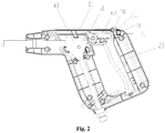
Fig. 2 illustrates a front view of the embodiment of the spray gun inFig. 1 ; and -
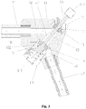
Fig. 3 illustrates an assembly drawing of a sealing assembly and a spray gun main body of the spray gun inFig. 1 . - The above accompanying drawings include the following reference numbers:
- 10. spray gun housing; 20. operating handle; 30. locking switch; 31. locking portion; 311. pressing part; 40. spray gun main body; 50. sealing assembly; 51. ejector rod; 60. connecting rod; 70. cushion block;
- 110. gas inlet pipe; 120. gas outlet pipe; 41. gas inlet passage; 42. gas outlet passage; 43. partition passage; 431. first hole section; 432. second hole section; 140. sealing ejector block; 141. partition flange; 150. elastic member; 160. sealing base; 170. first sealing ring; 180. ejector pin; 190. mounting base; 191. second sealing ring; 192. pressing block; 193. ejector block.
- It is to be noted that the embodiments in the application and the characteristics in the embodiments are combined under the condition of no conflicts. The disclosure is elaborated below with reference to the accompanying drawings and embodiments.
- The disclosure provides a spray gun housing, which includes a
spray gun housing 10 and anoperating handle 20. Referring toFig. 1 to Fig. 3 , the operatinghandle 20 is provided on thespray gun housing 10 to control connection and disconnection of a fluid of the spray gun by pulling theoperating handle 20. The spray gun further includes: a lockingswitch 30. The lockingswitch 30 is mounted on thespray gun housing 10 in a position-adjustable manner, and the lockingswitch 30 is located on one side of theoperating handle 20 and cooperates with the operatinghandle 20 in a limiting manner, so as to prevent the operating handle 20 from being pulled when the spray gun is in a non-operating state. - The spray gun in the disclosure includes the
spray gun housing 10, the operatinghandle 20, and the lockingswitch 30. The operatinghandle 20 is provided on thespray gun housing 10 to control the connection and disconnection of the fluid of the spray gun by pulling theoperating handle 20. The lockingswitch 30 is mounted on thespray gun housing 10 in a position-adjustable manner, and the lockingswitch 30 is located on one side of theoperating handle 20 and cooperates with the operatinghandle 20 in a limiting manner. In this way, when the spray gun is in the non-operating state, the operatinghandle 20 is prevented from being pulled, to prevent a user from pulling the operating handle 20 due to a misoperation, thereby preventing a damage of the spray gun to the user, and solving a problem of low safety performance of the spray gun known to inventors. - The spray gun in the disclosure includes a
gas inlet pipe 110 and agas outlet pipe 120. Referring toFig. 3 , the spray gun further includes: a spray gunmain body 40, both thegas inlet pipe 110 and thegas outlet pipe 120 being mounted on the spray gunmain body 40, and agas inlet passage 41 used for being in communicating with a pipe cavity of thegas inlet pipe 110 and agas outlet passage 42 used for communicating with a pipe cavity of thegas outlet pipe 120 being provided on the spray gunmain body 40; and a sealing assembly, at least a part of the sealing assembly being movably provided between thegas inlet passage 41 and thegas outlet passage 42, so as to cut off thegas inlet passage 41 and thegas outlet passage 42 or communicate thegas inlet passage 41 with thegas outlet passage 42. The sealing assembly includes apartition flange 141 used for cutting off thegas inlet passage 41 and thegas outlet passage 42 and anelastic member 150 connected with thepartition flange 141. Theelastic member 150 is provided in a retractable way to press thepartition flange 141 to a position that cutting off thegas inlet passage 41 and thegas outlet passage 42. - The spray gun in the disclosure includes the
gas inlet pipe 110, thegas outlet pipe 120, and the spray gunmain body 40. Both thegas inlet pipe 110 and thegas outlet pipe 120 are mounted on the spray gunmain body 40. Thegas inlet passage 41 used for being in communication with the pipe cavity of thegas inlet pipe 110 and thegas outlet passage 42 used for being in communication with the pipe cavity of thegas outlet pipe 120 are provided on the spray gunmain body 40. The spray gun further includes the sealing assembly. At least a part of the sealing assembly is movably provided between thegas inlet passage 41 and thegas outlet passage 42, so as to cut off the gas inlet passage and the gas outlet passage, or communicate the gas inlet passage and the gas outlet passage. To communicate or uncommunicate thegas inlet passage 41 and thegas outlet passage 42 fluidly, the sealing assembly includes thepartition flange 141 for cutting off thegas inlet passage 41 and thegas outlet passage 42 and theelastic member 150 connected with thepartition flange 141. By providing theelastic member 150 in a retractable way, thepartition flange 141 is pressed, under the action of theelastic member 150, at a position that cuts off thegas inlet passage 41 and thegas outlet passage 42, thereby thegas inlet passage 41 and thegas outlet passage 42 are not communicated fluidly; and only when acted upon by an external force, thepartition flange 141 overcomes the action of theelastic member 150 to communicate thegas inlet passage 41 and thegas outlet passage 42; in this way, the sealing effect of the spray gunmain body 40 is enhanced, and the problem that the sealing effect between the gas outlet pipe and the gas inlet pipe of the spray gun of the car washer known to inventors cannot be ensured is solved. - The main structure of the spray gun in the present embodiment is as follows. As shown in
Fig. 1 andFig. 2 , the spray gun further includes: the spray gunmain body 40, the spray gunmain body 40 being provided in thespray gun housing 10; and the sealingassembly 50, at least a part of the sealingassembly 50 is movably provided in the spray gunmain body 40, to control the connection and disconnection of the fluid in the spray gunmain body 40. The operatinghandle 20 is connected with the sealingassembly 50 to drive the sealingassembly 50 to move by pulling theoperating handle 20, so as to control the connection and disconnection of the fluid in the spray gunmain body 40. - It can be seen that the connection and disconnection of the fluid in the spray gun
main body 40 is controlled conveniently by pulling theoperating handle 20, and then the opening or closing of the spray gun is controlled conveniently. - To implement the connection between the operating
handle 20 and the sealingassembly 50, as shown inFig. 1 andFig. 2 , the spray gun further includes: a connectingrod 60. One end of the connectingrod 60 is connected with the sealingassembly 50, and the other end of the connectingrod 60 is connected to theoperating handle 20, so that the operating handle 20 drives, through the connectingrod 60, the sealingassembly 50 to move. - The specific form of the sealing
assembly 50 in the present embodiment is as follows: the sealingassembly 50 includes anejector rod 51 and a sealing part connected with theejector rod 51; the sealing part is provided in the fluid passage of the spray gunmain body 40 to control the connection and disconnection of the fluid passage; and the connectingrod 60 is connected with theejector rod 51 to drive theejector rod 51 to move. In this way, by making theejector rod 51 to move, the connection and disconnection of the fluid in the spray gunmain body 40 is controlled conveniently. - In the present embodiment, the locking
switch 30 is at a side, far away from the sealingassembly 50, of theoperating handle 20. In this way, the operatinghandle 20 is locked conveniently, to prevent the operating handle 20 from moving when the spray gun is in the non-operating state. - To lock the
operating handle 20, as shown inFig. 1 andFig. 2 , the lockingswitch 30 has a lockingportion 31; the lockingswitch 30 is movably provided along a direction close to or away from the operatinghandle 20, so that the lockingportion 31 is abutted against the operatinghandle 20, or the lockingportion 31 avoids the operatinghandle 20 to make the operating handle 20 move. - In an exemplary embodiment, the locking
switch 30 has a locking position used for limiting theoperating handle 20 and an avoiding position used for avoiding theoperating handle 20. The lockingswitch 30 is movably provided between the locking position and the avoiding position. The spray gun further includes acushion block 70. Thecushion block 70 is mounted on thespray gun housing 10. When the locking switching 30 is located at the locking position, thecushion block 70 is located on a side, far away from the operatinghandle 20, of the lockingportion 31 and is abutted against the lockingportion 31, so as to lock the lockingswitch 30 at the locking position. - To limit the locking
switch 30, as shown inFig. 1 andFig. 2 , thecushion block 70 is located between a locking position and an avoiding position of the lockingswitch 30. Thecushion block 70 is an elastic member, so that the lockingswitch 30 compresses thecushion block 70 to pass through thecushion block 70 when moving between the locking position and the avoiding position of the lockingswitch 30. - In some embodiments, the
cushion block 70 is a rubber block. - To compress the
cushion block 70 to move to the avoiding position after passing through thecushion block 70, apressing part 311 is provided on the lockingportion 31. When the lockingswitch 30 is located at the locking position, thepressing part 311 is pressed on thecushion block 70; when the lockingswitch 30 moves towards the avoiding position, thepressing part 311 compresses thecushion block 70 so as to make it shrink. - In an exemplary embodiment, an operating head is provided on the locking
switch 30. - The main structure of the spray gun
main body 40 is as follows. - To communicate or uncommunicate the
gas inlet passage 41 and thegas outlet passage 42, as shown inFig. 3 , apartition passage 43 is provided on the spray gunmain body 40. Thepartition passage 43 is located between thegas inlet passage 41 and thegas outlet passage 42. Thepartition passage 43 is in communication with both thegas inlet passage 41 and thegas outlet passage 42. Thepartition flange 141 is provided in thepartition passage 43 in a position-adjustable manner, so as to uncommunicate thegas inlet passage 41 and thegas outlet passage 42. - As shown in
Fig. 3 , the specific structure of thepartition passage 43 in the disclosure is that: thepartition passage 43 is a stepped hole including afirst hole section 431 and a second hole section 432; thefirst hole section 431 is in communication with thegas outlet passage 42; the second hole section 432 is in communication with thegas inlet passage 41; and thepartition passage 43 is occluded at a joint between thefirst hole section 431 and the second hole section 432. - To fix the whole sealing assembly, the sealing assembly further includes a
sealing base 160. One end of theelastic member 150 is abutted against the sealingbase 160, and the other end of theelastic member 150 is abutted against thepartition flange 141. - In some embodiments, the sealing
base 160 is a sealing nut. - To facilitate the sealing of the partition passage, as shown in
Fig. 3 , the sealing assembly further includes a sealingejector block 140. Thepartition flange 141 is provided on the sealingejector block 140, and theelastic member 150 is provided on the sealingejector block 140 in a sleeving manner. - In an exemplary embodiment, the
elastic member 150 is a spring. The sealingejector block 140 has a rod body portion, and the spring is provided on the rod body portion in a sleeving manner. - In some embodiments, the sealing assembly further includes a
first sealing ring 170. Thefirst sealing ring 170 is mounted on thepartition flange 141, so as to enhance a partition effect between thegas outlet passage 42 and thegas inlet passage 41. By setting thefirst sealing ring 170, the sealing effect of the sealing assembly is enhanced, thereby ensuring the partition effect between thegas outlet passage 42 and thegas inlet passage 41. - To push the
partition flange 141 to connect thegas outlet passage 42 and thegas inlet passage 41, as shown inFig. 3 , the spray gun further includes anejector pin 180. Theejector pin 180 is connected to thepartition flange 141, so that thepartition flange 141 is pushed by theejector pin 180 to move. - To locate the
ejector pin 180, as shown inFig. 3 , the spray gun further includes a mountingbase 190. The mountingbase 190 is provided on theejector pin 180 in a sleeving manner and connected with the spray gunmain body 40, so that theejector pin 180 is mounted on the spray gunmain body 40 through the mountingbase 190. - In an exemplary embodiment, the
ejector pin 180 is in threaded connection with the mountingbase 190 to make theejector pin 180 stretch and retract toward thepartition flange 141 by rotation, so as to drive thepartition flange 141 to stretch and retract to communicate thegas outlet passage 42 and thegas inlet passage 41. - To achieve the sealing effect between the spray gun
main body 40 and the mountingbase 190 and theejector pin 180, as shown inFig. 3 , a mounting chamber is provided on themount base 190, asecond sealing ring 191 is provided in the mounting chamber, and the mountingbase 190 is in sealed connection with the spray gunmain body 40 through thesecond sealing ring 191. - In some embodiments, the spray gun further includes a
pressing block 192. Thepressing block 192 is provided in the mounting chamber and pressed on thesecond sealing ring 191. In this way, the sealing effect is enhanced. - In some embodiments, an
ejector block 193 is provided on one end, far away from thepartition flange 141, of theejector pin 180. By setting theejector block 193, theejector pin 180 is operated conveniently. - Some embodiments of the disclosure also provide a car washer, which includes a steam generator and the spray gun abovementioned, wherein the spray gun is connected with the steam generator.
- It can be seen from above description that the above embodiments of the disclosure achieve the following technical effects.
- The spray gun in some embodiments of the disclosure includes the
gas inlet pipe 110, thegas outlet pipe 120, and the spray gunmain body 40. Both thegas inlet pipe 110 and thegas outlet pipe 120 are mounted on the spray gunmain body 40. Thegas inlet passage 41 used for being in communication with the pipe cavity of thegas inlet pipe 110 and thegas outlet passage 42 used for being in communication with the pipe cavity of thegas outlet pipe 120 are provided on the spray gunmain body 40. The spray gun further includes the sealing assembly. At least a part of the sealing assembly is movably provided between thegas inlet passage 41 and thegas outlet passage 42, so as to cut off thegas inlet passage 41 and thegas outlet passage 42, or communicate thegas inlet passage 41 and thegas outlet passage 42. To communicate or uncommunicate thegas inlet passage 41 and thegas outlet passage 42, the sealing assembly includes thepartition flange 141 for cutting off thegas inlet passage 41 and thegas outlet passage 42 and theelastic member 150 connected with thepartition flange 141. By providing theelastic member 150 in a retractable way, thepartition flange 141 is pressed, under the action of theelastic member 150, at the position that cuts off thegas inlet passage 41 and thegas outlet passage 42, thereby cutting off thegas inlet passage 41 and thegas outlet passage 42; and only when acted upon by an external force, thepartition flange 141 overcomes the action of theelastic member 150 to turn on thegas inlet passage 41 and thegas outlet passage 42; in this way, the sealing effect of the spray gunmain body 40 is enhanced, and the problem that the sealing effect between the gas outlet pipe and the gas inlet pipe of the spray gun of the car washer known to inventors cannot be ensured is solved. - The above is only some embodiments of the disclosure and not intended to limit the disclosure; for those skilled in the art, the disclosure has various modifications and changes. Any modifications, equivalent replacements, improvements and the like within the spirit and principle of the disclosure should fall within the protection scope of the claims of the disclosure.
Claims (10)
- A spray gun, comprising: a spray gun housing (10) and an operating handle (20), the operating handle (20) being provided on the spray gun housing (10) to control connection and disconnection of a fluid in the spray gun by pulling the operating handle (20); wherein the spray gun further comprises:a spray gun main body (40);a sealing assembly (50), at least a part of the sealing assembly (50) being movably provided in the spray gun main body (40) of the spray gun to control the connection and disconnection of a fluid in the spray gun main body (40), and the operating handle (20) being connected with the sealing assembly (50), so as to drive the sealing assembly (50) to move by pulling the operating handle (20), so that the connection and disconnection of the fluid in the spray gun main body is controlled; anda locking switch (30), mounted on the spray gun housing (10) in a position-adjustable manner, the locking switch (30) being located on one side of the operating handle (20) and cooperating with the operating handle (20) in a limiting manner, so as to prevent the operating handle (20) from being pulled when the spray gun is in a non-operating state;wherein the sealing assembly (50) comprises a partition flange (141) used for cutting off a fluid passage in the spray gun main body (40) and an elastic member (150) connected with the partition flange (141); and the elastic member (150) is provided in a retractable way to press the partition flange (141) to a position that cuts off the fluid passage of the spray gun main body (40).
- The spray gun as claimed in claim 1, further comprising:
a connecting rod (60), one end of the connecting rod (60) being connected with the sealing assembly (50), and the other end of the connecting rod (60) being connected with the operating handle (20), so that the operating handle (20) drives, through the connecting rod (60), the sealing assembly (50) to move. - The spray gun as claimed in claim 1, wherein the locking switch (30) is provided with a locking portion (31); the locking switch (30) is movably provided along a direction close to or away from the operating handle (20), so that the locking portion (31) is abutted against the operating handle (20), or the locking portion (31) avoids the operating handle (20) to make the operating handle (20) move.
- The spray gun as claimed in claim 3, wherein the locking switch (30) is provided with a locking position used for limiting the operating handle (20) and an avoiding position used for avoiding the operating handle (20); the locking switch (30) is movably provided between the locking position and the avoiding position; the spray gun further comprises a cushion block (70), the cushion block (70) being mounted on the spray gun housing (10); when the locking switching (30) is located at the locking position, the cushion block (70) is located on a side, far away from the operating handle (20), of the locking portion (31) and is abutted against the locking portion (31), so as to lock the locking switch (30) at the locking position.
- The spray gun as claimed in claim 1, further comprising: a gas inlet pipe (110) and a gas outlet pipe (120); both the gas inlet pipe (110) and the gas outlet pipe (120) are mounted on the spray gun main body (40); a gas inlet passage (41) used for being in communication with a pipe cavity of the gas inlet pipe (110) and a gas outlet passage (42) used for being in communication with a pipe cavity of the gas outlet pipe (120) are provided on the spray gun main body (40); wherein, at least a part of the sealing assembly is movably provided between the gas inlet passage (41) and the gas outlet passage (42), so as to cut off the gas inlet passage (41) and the gas outlet passage (42), or communicate the gas inlet passage (41) and the gas outlet passage (42).
- The spray gun as claimed in claim 5, wherein a partition passage (43) is provided on the spray gun main body (40); the partition passage (43) is located between the gas inlet passage (41) and the gas outlet passage (42); the partition passage (43) is in communication with both the gas inlet passage (41) and the gas outlet passage (42); the partition flange (141) is provided in the partition passage (43) in a position-adjustable manner, so as to cut off the gas inlet passage (41) and the gas outlet passage (42).
- The spray gun as claimed in claim 6, wherein the partition passage (43) is a stepped hole comprising a first hole section (431) and a second hole section (432); the first hole section (431) is in communication with the gas outlet passage (42); the second hole section (432) is in communication with the gas inlet passage (41); and the partition passage (43) is occluded at a joint between the first hole section (431) and the second hole section (432).
- The spray gun as claimed in claim 1, wherein the sealing assembly further comprises a sealing base (160); one end of the elastic member (150) is abutted against the sealing base (160), and the other end of the elastic member (150) is abutted against the partition flange (141).
- The spray gun as claimed in claim 1, further comprising: an ejector pin (180); the ejector pin (180) is connected with the partition flange (141), so that the partition flange (141) is pushed to move through the ejector pin (180).
- A car washer, comprising a steam generator and the spray gun as claimed in any one of claims 1 to 9, wherein the spray gun is connected with the steam generator.
Applications Claiming Priority (2)
| Application Number | Priority Date | Filing Date | Title |
|---|---|---|---|
| CN201711498450.8A CN108128281B (en) | 2017-12-28 | 2017-12-28 | Spray gun and car washer with same |
| PCT/CN2018/097969 WO2019128224A1 (en) | 2017-12-28 | 2018-08-01 | Spray gun and car washing machine provided with same |
Publications (3)
| Publication Number | Publication Date |
|---|---|
| EP3733463A1 true EP3733463A1 (en) | 2020-11-04 |
| EP3733463A4 EP3733463A4 (en) | 2021-10-06 |
| EP3733463B1 EP3733463B1 (en) | 2023-11-22 |
Family
ID=62399329
Family Applications (1)
| Application Number | Title | Priority Date | Filing Date |
|---|---|---|---|
| EP18897749.0A Active EP3733463B1 (en) | 2017-12-28 | 2018-08-01 | Spray gun and car washing machine provided with same |
Country Status (4)
| Country | Link |
|---|---|
| US (1) | US20200290573A1 (en) |
| EP (1) | EP3733463B1 (en) |
| CN (1) | CN108128281B (en) |
| WO (1) | WO2019128224A1 (en) |
Families Citing this family (4)
| Publication number | Priority date | Publication date | Assignee | Title |
|---|---|---|---|---|
| CN108128281B (en) * | 2017-12-28 | 2024-03-08 | 珠海格力智能装备有限公司 | Spray gun and car washer with same |
| CN109398325B (en) * | 2018-12-17 | 2024-03-08 | 珠海格力智能装备有限公司 | Spray gun and steam car washer with same |
| CN110508558B (en) * | 2019-09-19 | 2024-05-03 | 吴海 | Spring-free dust blowing gun |
| IT202100010073A1 (en) * | 2021-04-21 | 2022-10-21 | Tecomec Srl | GUN FOR PRESSURE WASHER |
Family Cites Families (20)
| Publication number | Priority date | Publication date | Assignee | Title |
|---|---|---|---|---|
| GB726778A (en) * | 1950-12-12 | 1955-03-23 | Bruno Agosti | An apparatus for continuously preparing and distributing detergent foamy solutions, especially for washing glossy surfaces such as vehicle bodies, glass surfaces and thelike |
| NZ184873A (en) * | 1976-08-27 | 1980-02-21 | Tricentrol Mfg Pty Ltd | Spray gun means to regulate flow of air from high pressure source to air galleries of gun |
| US4483483A (en) * | 1980-11-12 | 1984-11-20 | Champion Spark Plug Company | Gun for supplying compressed fluid |
| DE3407744C2 (en) * | 1984-03-02 | 1986-01-23 | Alfred Kärcher GmbH & Co, 7057 Winnenden | Hand spray gun for a high pressure cleaning device |
| JPH07171447A (en) * | 1993-12-22 | 1995-07-11 | Kitagawa Ind Co Ltd | Additional liquid feeder and sprinkler nozzle |
| US5529245A (en) * | 1994-06-23 | 1996-06-25 | Insta-Foam Products | Low cost dispenser for multi-component foams |
| US7124965B1 (en) * | 2004-09-27 | 2006-10-24 | Shin Tai Spurt Water Of The Garden Tools Co., Ltd. | Spraying gun |
| WO2007126998A2 (en) * | 2006-03-29 | 2007-11-08 | Spraying Systems Co. | Hand held trigger-operated spray gun |
| CN201419147Y (en) * | 2009-03-31 | 2010-03-10 | 厦门建霖工业有限公司 | Control structure for spray gun switch |
| US9192950B2 (en) * | 2009-11-20 | 2015-11-24 | Wagner Spray Tech Corporation | Sprayer for a fluid delivery system |
| CN201823660U (en) * | 2010-09-25 | 2011-05-11 | 孟丽娟 | Speedy PU (polyurethane) spray gun locking device |
| CN102371975B (en) * | 2011-08-26 | 2013-06-19 | 台州市黄岩科丰机电有限公司 | Car washing device spray gun with cleaning liquid and multi-orifice shower nozzle |
| CN103406224B (en) * | 2013-08-01 | 2015-10-21 | 宁波大叶园林科技有限公司 | A kind of hydraulic giant of antifreeze far-end sealing |
| US10130962B2 (en) * | 2013-10-10 | 2018-11-20 | Briggs & Stratton Corporation | Wirelessly controlled trigger start and chemical tank change-over for pressure washers |
| CN204107718U (en) * | 2014-07-11 | 2015-01-21 | 张恒彪 | Multifunctional car-washing hydraulic giant |
| CN204279370U (en) * | 2014-11-22 | 2015-04-22 | 广西凯纵机械制造有限公司 | A kind of car washing gun |
| CN108128282B (en) * | 2017-12-28 | 2024-02-27 | 珠海格力智能装备有限公司 | Car washer |
| CN207809346U (en) * | 2017-12-28 | 2018-09-04 | 珠海格力智能装备有限公司 | Spray gun and car washer with same |
| CN108128281B (en) * | 2017-12-28 | 2024-03-08 | 珠海格力智能装备有限公司 | Spray gun and car washer with same |
| CN207809342U (en) * | 2017-12-28 | 2018-09-04 | 珠海格力智能装备有限公司 | Car washer |
-
2017
- 2017-12-28 CN CN201711498450.8A patent/CN108128281B/en active Active
-
2018
- 2018-08-01 EP EP18897749.0A patent/EP3733463B1/en active Active
- 2018-08-01 US US16/651,207 patent/US20200290573A1/en not_active Abandoned
- 2018-08-01 WO PCT/CN2018/097969 patent/WO2019128224A1/en unknown
Also Published As
| Publication number | Publication date |
|---|---|
| EP3733463B1 (en) | 2023-11-22 |
| US20200290573A1 (en) | 2020-09-17 |
| WO2019128224A1 (en) | 2019-07-04 |
| CN108128281A (en) | 2018-06-08 |
| CN108128281B (en) | 2024-03-08 |
| EP3733463A4 (en) | 2021-10-06 |
Similar Documents
| Publication | Publication Date | Title |
|---|---|---|
| EP3733463B1 (en) | Spray gun and car washing machine provided with same | |
| US8632021B2 (en) | Pump head assembly and pressure washer with such pump head assembly | |
| CN212397045U (en) | Shower head with spray gun | |
| CN109350236B (en) | Electric coagulation shear and clamp head processing technology thereof | |
| US11571720B2 (en) | Carwash machine | |
| KR20080002531U (en) | Bidet | |
| US3058668A (en) | Cleaning apparatus | |
| WO2019137400A1 (en) | Exhaust hood, joint assembly for exhaust hood, and cleaning system | |
| CN215019440U (en) | Tooth flushing device | |
| CN104701040B (en) | A kind of cleaning machine with switch box structure | |
| CN108128283B (en) | Spray gun and car washer with same | |
| CN107552474A (en) | A kind of binary channels substation cleaning device | |
| CN207463723U (en) | A kind of binary channels substation cleaning device | |
| CN108787552B (en) | High-pressure cleaning machine | |
| CN209975653U (en) | Sanitary flushing control system for toilet cover | |
| CN209316662U (en) | A kind of Vigina cleaner | |
| CN104863227A (en) | Manual and automatic button for water discharge valve | |
| CN204863527U (en) | Water toothpick | |
| CN217502757U (en) | Labor-saving water outlet device capable of switching water supply and water supply cut-off | |
| CN112071688B (en) | Double-acting flushing button switch, excrement collecting system and method | |
| KR200151413Y1 (en) | Injection struction in washer in automobile | |
| JP3538966B2 (en) | Fluid supply device for cleaning | |
| DE19530187C1 (en) | Power-on device for vacuum cleaner | |
| JP3053670U (en) | Can crusher equipment | |
| CN207033672U (en) | Jetting machine |
Legal Events
| Date | Code | Title | Description |
|---|---|---|---|
| STAA | Information on the status of an ep patent application or granted ep patent |
Free format text: STATUS: THE INTERNATIONAL PUBLICATION HAS BEEN MADE |
|
| PUAI | Public reference made under article 153(3) epc to a published international application that has entered the european phase |
Free format text: ORIGINAL CODE: 0009012 |
|
| STAA | Information on the status of an ep patent application or granted ep patent |
Free format text: STATUS: REQUEST FOR EXAMINATION WAS MADE |
|
| 17P | Request for examination filed |
Effective date: 20200312 |
|
| AK | Designated contracting states |
Kind code of ref document: A1 Designated state(s): AL AT BE BG CH CY CZ DE DK EE ES FI FR GB GR HR HU IE IS IT LI LT LU LV MC MK MT NL NO PL PT RO RS SE SI SK SM TR |
|
| AX | Request for extension of the european patent |
Extension state: BA ME |
|
| DAV | Request for validation of the european patent (deleted) | ||
| DAX | Request for extension of the european patent (deleted) | ||
| A4 | Supplementary search report drawn up and despatched |
Effective date: 20210903 |
|
| RIC1 | Information provided on ipc code assigned before grant |
Ipc: F16K 3/24 20060101ALI20210830BHEP Ipc: B60S 3/04 20060101AFI20210830BHEP |
|
| STAA | Information on the status of an ep patent application or granted ep patent |
Free format text: STATUS: EXAMINATION IS IN PROGRESS |
|
| 17Q | First examination report despatched |
Effective date: 20230117 |
|
| GRAP | Despatch of communication of intention to grant a patent |
Free format text: ORIGINAL CODE: EPIDOSNIGR1 |
|
| STAA | Information on the status of an ep patent application or granted ep patent |
Free format text: STATUS: GRANT OF PATENT IS INTENDED |
|
| P01 | Opt-out of the competence of the unified patent court (upc) registered |
Effective date: 20230530 |
|
| INTG | Intention to grant announced |
Effective date: 20230703 |
|
| GRAS | Grant fee paid |
Free format text: ORIGINAL CODE: EPIDOSNIGR3 |
|
| GRAA | (expected) grant |
Free format text: ORIGINAL CODE: 0009210 |
|
| STAA | Information on the status of an ep patent application or granted ep patent |
Free format text: STATUS: THE PATENT HAS BEEN GRANTED |
|
| AK | Designated contracting states |
Kind code of ref document: B1 Designated state(s): AL AT BE BG CH CY CZ DE DK EE ES FI FR GB GR HR HU IE IS IT LI LT LU LV MC MK MT NL NO PL PT RO RS SE SI SK SM TR |
|
| REG | Reference to a national code |
Ref country code: GB Ref legal event code: FG4D |
|
| REG | Reference to a national code |
Ref country code: CH Ref legal event code: EP |
|
| REG | Reference to a national code |
Ref country code: DE Ref legal event code: R096 Ref document number: 602018061641 Country of ref document: DE |
|
| REG | Reference to a national code |
Ref country code: IE Ref legal event code: FG4D |
|
| REG | Reference to a national code |
Ref country code: LT Ref legal event code: MG9D |
|
| REG | Reference to a national code |
Ref country code: NL Ref legal event code: MP Effective date: 20231122 |
|
| PG25 | Lapsed in a contracting state [announced via postgrant information from national office to epo] |
Ref country code: GR Free format text: LAPSE BECAUSE OF FAILURE TO SUBMIT A TRANSLATION OF THE DESCRIPTION OR TO PAY THE FEE WITHIN THE PRESCRIBED TIME-LIMIT Effective date: 20240223 |
|
| PG25 | Lapsed in a contracting state [announced via postgrant information from national office to epo] |
Ref country code: IS Free format text: LAPSE BECAUSE OF FAILURE TO SUBMIT A TRANSLATION OF THE DESCRIPTION OR TO PAY THE FEE WITHIN THE PRESCRIBED TIME-LIMIT Effective date: 20240322 |
|
| PG25 | Lapsed in a contracting state [announced via postgrant information from national office to epo] |
Ref country code: LT Free format text: LAPSE BECAUSE OF FAILURE TO SUBMIT A TRANSLATION OF THE DESCRIPTION OR TO PAY THE FEE WITHIN THE PRESCRIBED TIME-LIMIT Effective date: 20231122 |
|
| REG | Reference to a national code |
Ref country code: AT Ref legal event code: MK05 Ref document number: 1633558 Country of ref document: AT Kind code of ref document: T Effective date: 20231122 |
|
| PG25 | Lapsed in a contracting state [announced via postgrant information from national office to epo] |
Ref country code: NL Free format text: LAPSE BECAUSE OF FAILURE TO SUBMIT A TRANSLATION OF THE DESCRIPTION OR TO PAY THE FEE WITHIN THE PRESCRIBED TIME-LIMIT Effective date: 20231122 |
|
| PG25 | Lapsed in a contracting state [announced via postgrant information from national office to epo] |
Ref country code: AT Free format text: LAPSE BECAUSE OF FAILURE TO SUBMIT A TRANSLATION OF THE DESCRIPTION OR TO PAY THE FEE WITHIN THE PRESCRIBED TIME-LIMIT Effective date: 20231122 |
|
| PG25 | Lapsed in a contracting state [announced via postgrant information from national office to epo] |
Ref country code: ES Free format text: LAPSE BECAUSE OF FAILURE TO SUBMIT A TRANSLATION OF THE DESCRIPTION OR TO PAY THE FEE WITHIN THE PRESCRIBED TIME-LIMIT Effective date: 20231122 |
|
| PG25 | Lapsed in a contracting state [announced via postgrant information from national office to epo] |
Ref country code: NL Free format text: LAPSE BECAUSE OF FAILURE TO SUBMIT A TRANSLATION OF THE DESCRIPTION OR TO PAY THE FEE WITHIN THE PRESCRIBED TIME-LIMIT Effective date: 20231122 Ref country code: LT Free format text: LAPSE BECAUSE OF FAILURE TO SUBMIT A TRANSLATION OF THE DESCRIPTION OR TO PAY THE FEE WITHIN THE PRESCRIBED TIME-LIMIT Effective date: 20231122 Ref country code: IS Free format text: LAPSE BECAUSE OF FAILURE TO SUBMIT A TRANSLATION OF THE DESCRIPTION OR TO PAY THE FEE WITHIN THE PRESCRIBED TIME-LIMIT Effective date: 20240322 Ref country code: GR Free format text: LAPSE BECAUSE OF FAILURE TO SUBMIT A TRANSLATION OF THE DESCRIPTION OR TO PAY THE FEE WITHIN THE PRESCRIBED TIME-LIMIT Effective date: 20240223 Ref country code: ES Free format text: LAPSE BECAUSE OF FAILURE TO SUBMIT A TRANSLATION OF THE DESCRIPTION OR TO PAY THE FEE WITHIN THE PRESCRIBED TIME-LIMIT Effective date: 20231122 Ref country code: BG Free format text: LAPSE BECAUSE OF FAILURE TO SUBMIT A TRANSLATION OF THE DESCRIPTION OR TO PAY THE FEE WITHIN THE PRESCRIBED TIME-LIMIT Effective date: 20240222 Ref country code: AT Free format text: LAPSE BECAUSE OF FAILURE TO SUBMIT A TRANSLATION OF THE DESCRIPTION OR TO PAY THE FEE WITHIN THE PRESCRIBED TIME-LIMIT Effective date: 20231122 Ref country code: PT Free format text: LAPSE BECAUSE OF FAILURE TO SUBMIT A TRANSLATION OF THE DESCRIPTION OR TO PAY THE FEE WITHIN THE PRESCRIBED TIME-LIMIT Effective date: 20240322 |
|
| PG25 | Lapsed in a contracting state [announced via postgrant information from national office to epo] |
Ref country code: SE Free format text: LAPSE BECAUSE OF FAILURE TO SUBMIT A TRANSLATION OF THE DESCRIPTION OR TO PAY THE FEE WITHIN THE PRESCRIBED TIME-LIMIT Effective date: 20231122 Ref country code: RS Free format text: LAPSE BECAUSE OF FAILURE TO SUBMIT A TRANSLATION OF THE DESCRIPTION OR TO PAY THE FEE WITHIN THE PRESCRIBED TIME-LIMIT Effective date: 20231122 Ref country code: PL Free format text: LAPSE BECAUSE OF FAILURE TO SUBMIT A TRANSLATION OF THE DESCRIPTION OR TO PAY THE FEE WITHIN THE PRESCRIBED TIME-LIMIT Effective date: 20231122 Ref country code: NO Free format text: LAPSE BECAUSE OF FAILURE TO SUBMIT A TRANSLATION OF THE DESCRIPTION OR TO PAY THE FEE WITHIN THE PRESCRIBED TIME-LIMIT Effective date: 20240222 Ref country code: LV Free format text: LAPSE BECAUSE OF FAILURE TO SUBMIT A TRANSLATION OF THE DESCRIPTION OR TO PAY THE FEE WITHIN THE PRESCRIBED TIME-LIMIT Effective date: 20231122 Ref country code: HR Free format text: LAPSE BECAUSE OF FAILURE TO SUBMIT A TRANSLATION OF THE DESCRIPTION OR TO PAY THE FEE WITHIN THE PRESCRIBED TIME-LIMIT Effective date: 20231122 |
|
| PG25 | Lapsed in a contracting state [announced via postgrant information from national office to epo] |
Ref country code: DK Free format text: LAPSE BECAUSE OF FAILURE TO SUBMIT A TRANSLATION OF THE DESCRIPTION OR TO PAY THE FEE WITHIN THE PRESCRIBED TIME-LIMIT Effective date: 20231122 |
|
| PG25 | Lapsed in a contracting state [announced via postgrant information from national office to epo] |
Ref country code: CZ Free format text: LAPSE BECAUSE OF FAILURE TO SUBMIT A TRANSLATION OF THE DESCRIPTION OR TO PAY THE FEE WITHIN THE PRESCRIBED TIME-LIMIT Effective date: 20231122 |
|
| PG25 | Lapsed in a contracting state [announced via postgrant information from national office to epo] |
Ref country code: SK Free format text: LAPSE BECAUSE OF FAILURE TO SUBMIT A TRANSLATION OF THE DESCRIPTION OR TO PAY THE FEE WITHIN THE PRESCRIBED TIME-LIMIT Effective date: 20231122 |
|
| PG25 | Lapsed in a contracting state [announced via postgrant information from national office to epo] |
Ref country code: SM Free format text: LAPSE BECAUSE OF FAILURE TO SUBMIT A TRANSLATION OF THE DESCRIPTION OR TO PAY THE FEE WITHIN THE PRESCRIBED TIME-LIMIT Effective date: 20231122 Ref country code: SK Free format text: LAPSE BECAUSE OF FAILURE TO SUBMIT A TRANSLATION OF THE DESCRIPTION OR TO PAY THE FEE WITHIN THE PRESCRIBED TIME-LIMIT Effective date: 20231122 Ref country code: RO Free format text: LAPSE BECAUSE OF FAILURE TO SUBMIT A TRANSLATION OF THE DESCRIPTION OR TO PAY THE FEE WITHIN THE PRESCRIBED TIME-LIMIT Effective date: 20231122 Ref country code: IT Free format text: LAPSE BECAUSE OF FAILURE TO SUBMIT A TRANSLATION OF THE DESCRIPTION OR TO PAY THE FEE WITHIN THE PRESCRIBED TIME-LIMIT Effective date: 20231122 Ref country code: EE Free format text: LAPSE BECAUSE OF FAILURE TO SUBMIT A TRANSLATION OF THE DESCRIPTION OR TO PAY THE FEE WITHIN THE PRESCRIBED TIME-LIMIT Effective date: 20231122 Ref country code: DK Free format text: LAPSE BECAUSE OF FAILURE TO SUBMIT A TRANSLATION OF THE DESCRIPTION OR TO PAY THE FEE WITHIN THE PRESCRIBED TIME-LIMIT Effective date: 20231122 Ref country code: CZ Free format text: LAPSE BECAUSE OF FAILURE TO SUBMIT A TRANSLATION OF THE DESCRIPTION OR TO PAY THE FEE WITHIN THE PRESCRIBED TIME-LIMIT Effective date: 20231122 |