EP3733078A1 - Écarteur - Google Patents
Écarteur Download PDFInfo
- Publication number
- EP3733078A1 EP3733078A1 EP20180562.9A EP20180562A EP3733078A1 EP 3733078 A1 EP3733078 A1 EP 3733078A1 EP 20180562 A EP20180562 A EP 20180562A EP 3733078 A1 EP3733078 A1 EP 3733078A1
- Authority
- EP
- European Patent Office
- Prior art keywords
- blade
- axis
- retractor
- clause
- blades
- Prior art date
- Legal status (The legal status is an assumption and is not a legal conclusion. Google has not performed a legal analysis and makes no representation as to the accuracy of the status listed.)
- Withdrawn
Links
- 230000007246 mechanism Effects 0.000 claims description 95
- 239000000523 sample Substances 0.000 claims description 82
- 230000033001 locomotion Effects 0.000 claims description 36
- 238000000034 method Methods 0.000 abstract description 38
- 230000000712 assembly Effects 0.000 abstract description 23
- 238000000429 assembly Methods 0.000 abstract description 23
- 210000001519 tissue Anatomy 0.000 description 28
- 238000001356 surgical procedure Methods 0.000 description 11
- 238000003780 insertion Methods 0.000 description 10
- 230000037431 insertion Effects 0.000 description 10
- 230000014759 maintenance of location Effects 0.000 description 7
- 230000013011 mating Effects 0.000 description 6
- 238000013519 translation Methods 0.000 description 5
- 239000000463 material Substances 0.000 description 4
- 230000008901 benefit Effects 0.000 description 3
- 238000004891 communication Methods 0.000 description 3
- 238000003384 imaging method Methods 0.000 description 3
- 239000007943 implant Substances 0.000 description 3
- 210000005036 nerve Anatomy 0.000 description 3
- 239000000919 ceramic Substances 0.000 description 2
- 230000000295 complement effect Effects 0.000 description 2
- 230000035876 healing Effects 0.000 description 2
- 229910052751 metal Inorganic materials 0.000 description 2
- 239000002184 metal Substances 0.000 description 2
- 230000001954 sterilising effect Effects 0.000 description 2
- 238000004659 sterilization and disinfection Methods 0.000 description 2
- 241001279686 Allium moly Species 0.000 description 1
- 229910000684 Cobalt-chrome Inorganic materials 0.000 description 1
- RTAQQCXQSZGOHL-UHFFFAOYSA-N Titanium Chemical compound [Ti] RTAQQCXQSZGOHL-UHFFFAOYSA-N 0.000 description 1
- 208000027418 Wounds and injury Diseases 0.000 description 1
- 239000000853 adhesive Substances 0.000 description 1
- 230000001070 adhesive effect Effects 0.000 description 1
- 238000004873 anchoring Methods 0.000 description 1
- 239000000560 biocompatible material Substances 0.000 description 1
- 210000000988 bone and bone Anatomy 0.000 description 1
- 239000010952 cobalt-chrome Substances 0.000 description 1
- 230000008878 coupling Effects 0.000 description 1
- 238000010168 coupling process Methods 0.000 description 1
- 238000005859 coupling reaction Methods 0.000 description 1
- 238000005520 cutting process Methods 0.000 description 1
- 230000006378 damage Effects 0.000 description 1
- 230000007423 decrease Effects 0.000 description 1
- 238000002594 fluoroscopy Methods 0.000 description 1
- 230000004927 fusion Effects 0.000 description 1
- 238000010348 incorporation Methods 0.000 description 1
- 208000014674 injury Diseases 0.000 description 1
- 230000003993 interaction Effects 0.000 description 1
- 238000005304 joining Methods 0.000 description 1
- 210000004705 lumbosacral region Anatomy 0.000 description 1
- 150000002739 metals Chemical class 0.000 description 1
- 229920000642 polymer Polymers 0.000 description 1
- 230000002980 postoperative effect Effects 0.000 description 1
- 238000003825 pressing Methods 0.000 description 1
- 210000002097 psoas muscle Anatomy 0.000 description 1
- 238000011084 recovery Methods 0.000 description 1
- 230000004044 response Effects 0.000 description 1
- 230000000717 retained effect Effects 0.000 description 1
- 230000007480 spreading Effects 0.000 description 1
- 238000003892 spreading Methods 0.000 description 1
- 239000010935 stainless steel Substances 0.000 description 1
- 229910001220 stainless steel Inorganic materials 0.000 description 1
- 230000004936 stimulating effect Effects 0.000 description 1
- 238000006467 substitution reaction Methods 0.000 description 1
- 239000003356 suture material Substances 0.000 description 1
- 239000010936 titanium Substances 0.000 description 1
- 229910052719 titanium Inorganic materials 0.000 description 1
Images


Classifications
-
- A—HUMAN NECESSITIES
- A61—MEDICAL OR VETERINARY SCIENCE; HYGIENE
- A61B—DIAGNOSIS; SURGERY; IDENTIFICATION
- A61B17/00—Surgical instruments, devices or methods, e.g. tourniquets
- A61B17/02—Surgical instruments, devices or methods, e.g. tourniquets for holding wounds open; Tractors
- A61B17/0206—Surgical instruments, devices or methods, e.g. tourniquets for holding wounds open; Tractors with antagonistic arms as supports for retractor elements
-
- A—HUMAN NECESSITIES
- A61—MEDICAL OR VETERINARY SCIENCE; HYGIENE
- A61B—DIAGNOSIS; SURGERY; IDENTIFICATION
- A61B17/00—Surgical instruments, devices or methods, e.g. tourniquets
- A61B17/02—Surgical instruments, devices or methods, e.g. tourniquets for holding wounds open; Tractors
- A61B17/025—Joint distractors
-
- A—HUMAN NECESSITIES
- A61—MEDICAL OR VETERINARY SCIENCE; HYGIENE
- A61B—DIAGNOSIS; SURGERY; IDENTIFICATION
- A61B5/00—Measuring for diagnostic purposes; Identification of persons
- A61B5/48—Other medical applications
- A61B5/4887—Locating particular structures in or on the body
- A61B5/4893—Nerves
-
- A—HUMAN NECESSITIES
- A61—MEDICAL OR VETERINARY SCIENCE; HYGIENE
- A61N—ELECTROTHERAPY; MAGNETOTHERAPY; RADIATION THERAPY; ULTRASOUND THERAPY
- A61N1/00—Electrotherapy; Circuits therefor
- A61N1/02—Details
- A61N1/04—Electrodes
- A61N1/05—Electrodes for implantation or insertion into the body, e.g. heart electrode
- A61N1/0551—Spinal or peripheral nerve electrodes
-
- A—HUMAN NECESSITIES
- A61—MEDICAL OR VETERINARY SCIENCE; HYGIENE
- A61B—DIAGNOSIS; SURGERY; IDENTIFICATION
- A61B17/00—Surgical instruments, devices or methods, e.g. tourniquets
- A61B17/02—Surgical instruments, devices or methods, e.g. tourniquets for holding wounds open; Tractors
- A61B17/025—Joint distractors
- A61B2017/0256—Joint distractors for the spine
- A61B2017/0262—Joint distractors for the spine with a provision for protecting nerves
Definitions
- the present application relates to surgical methods and tools, and more particularly to a retractor and a method of operating a retractor.
- Retractors are surgical devices used to spread bodily tissues in order to allow a surgeon or surgical assistant to see and access a part of the body that is to be surgically treated.
- retractors comprise a pair of jaws or blades that grip the bodily tissue and push it apart under the force generated by an actuator, such as a pair of scissor-like arms having a distal end and a proximal end.
- the proximal end generally defines a pair of handles and the distal end attaches to the pair of blades so that manipulation of the handles causes the blades to move apart from one another.
- the blades are inserted into the incision and the actuator is manipulated to move the blades of the retractor apart, thus spreading the tissue and providing an aperture through which the surgeon can access visualize the tissue to be surgically treated.
- the aperture size is generally limited by the size of the incision, meaning that a large aperture requires a relatively large incision.
- the drawback to this arrangement is that larger incisions result in the need for longer periods for healing of the incision. There is thus a need for a surgical retractor that is capable of creating a relatively large aperture using a relatively small incision, thereby reducing the invasiveness of the surgical procedure, post-operative healing times and patient discomfort.
- the retractor of the illustrated embodiment allows a person to insert a relatively compact set of retractor blades into an incision having a short length.
- the compact set of retractor blades e.g., a first blade, a second blade, a third blade
- the compact set of retractor blades are of such a size that they can be inserted within the incision so that they are snugly embraced by the side walls of the incision (e.g. a closed position).
- an actuator causes the first blade and the second blade to move apart (e.g., to an opened position) in a direction that can be essentially parallel to the length of the incision. This can cause the tissue to stretch in one direction (e.g., along the length of the incision), creating an opening having a length in that direction that is substantially longer than the incision.
- the actuator may be locked open.
- a rotation mechanism on the first and/or second blades may be manipulated to rotate the blades (e.g., to a rotated position), for example, pulling the incised tissue apart in one or more directions that are not parallel to the incision.
- a pivot mechanism on the first and/or second blades can be manipulated to pivot the blades (e.g., to a pivoted position), pulling the incised tissue apart in one or more directions that are not parallel to the incision.
- an adjuster on the first and/or second arms can be manipulated to slide or otherwise translate the arms (e.g., to a slide position), pulling the incised tissue apart in directions that are not parallel to the incision. In some embodiments, these directions may be perpendicular, substantially perpendicular or oblique to the incision.
- the retractor can be used to open up an aperture that is substantially longer and/or wider than the incision, and is substantially larger than would be possible using a prior art device and/or in a manner that is easier to use and/or requiring less steps and/or less complicated steps.
- the surgeon can use a smaller incision, and in some cases a much smaller incision, than would have been required with a prior art device.
- removal of the retractor e.g. by closing the blades, closing the arms and removing the blades from the incision, can allow the incision to relax back to a size that is much smaller than would have resulted from use of the prior art retractor.
- steps performed by the surgeon to retract the tissue can be simplified, easier to use and/or involve less steps as compared to prior art devices.
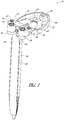
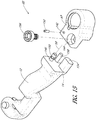
- FIG. 1 there is shown a perspective view of a retractor 10 having a body 26.
- the retractor 10 comprises a first arm 12, having a distal end 14 to which can be coupled a first blade assembly 16 comprising a first blade 18.
- the first blade assembly 16 can include a first rotation mechanism 20 to rotate the first blade 18.
- the first blade assembly 16 can also include a first pivot mechanism 22 to pivot the first blade 18.
- the first arm 12 has a proximal end 24 which is coupled to the body 26.
- the retractor 10 can include a second arm 32, having a distal end 34, to which can be coupled a second blade assembly 36 comprising a second blade 38.
- the second blade assembly 36 can include a second rotation mechanism 40 to rotate the second blade 38.
- the second blade assembly 36 can include a second pivot mechanism 42 to pivot the second blade 38.
- the second arm 32 has a proximal end 44 which is coupled to the body 26.
- the retractor can include a third blade 46 coupled to the body 26.
- the third blade 46 can include a longitudinally extending slot 48 sized to accept a probe 400, described herein.
- the probe 400 can be configured to be inserted from the tip of the third blade 46 toward the body 26.
- Other configurations are contemplated.
- the third blade 46 can include a connector 50.
- the connector 50 is a male connector.
- the body 26 can include a connector 28, which in the illustrated embodiment is a female connector.
- the connector 50 of the third blade 46 coupled with the connector 28 of the body 26 to hold the third blade 46 stationary in relation to the body 26.
- the third blade 46 is configured to be inserted from underneath the body 26.
- the connectors 50, 28 interlock to securely couple the third blade 46 to the body.
- the connectors 50, 28 form a snap fit.
- the connectors 50, 28 make an audible noise when the third blade 46 is coupled to the body 26.
- Other configurations for coupling these two components together are contemplated, such as, for example reversing the male/female connection and/or permanently connecting the parts and/or forming the parts out of more or less components.
- the first rotation mechanism 20 rotates the first blade 18 about a first axis 52.
- the second rotation mechanism 40 rotates the second blade 38 about a second axis 54.
- the first axis 52 passes vertically or substantially vertically through the first blade 18, and the second axis passes vertically or substantially vertically through second blade 38.
- the first and second axes may be substantially coplanar with one another. Indeed in some embodiments, the first and second axes are not only coplanar but also substantially parallel to one another. In particular embodiments, the first and second axes are coplanar with, parallel to, or at some pre-determined skew angle with respect to one another.
- substantially vertically, parallel, coplanar and/or perpendicular.
- substantially can mean within plus or minus 25 degrees from the given orientation, in other embodiments, within plus or minus 10 degrees from the given orientation, and in other embodiments, within plus or minus 5 degrees from the given orientation.
- first blade assembly 16 and the second blade assembly 36 can translate along a third axis 56 (see e.g., Figure 3 ).
- first blade assembly 16 and the second blade assembly 36 can move relative to one another along an arc.
- their general direction of motion relative to one another, and the direction of motion can be along the common third axis 56 that is generally defined by a line passing through the first axis 52 and the second axis 54.
- the first blade assembly 16 and the second blade assembly 36 can rotate about different axes (e.g., axes that are parallel to each other or slightly skewed).
- the third axis is perpendicular or substantially perpendicular to the first axis, the second axis or both the first and second axes. In particular embodiments, the third axis is substantially perpendicular or perpendicular to both the first axis and the second axis. In some embodiments, the third axis is substantially perpendicular or perpendicular to the first axis, the second axis or both the first and second axes. In some embodiments, the third axis is perpendicular or substantially perpendicular to both the first and second axes. In some embodiments, the retractor described herein possesses a mechanism (e.g., set screw, set pin, clamp, detent, ratchet mechanism etc.) for locking the arms 12, 32 in at least one predetermined position along the third axis 56.
- a mechanism e.g., set screw, set pin, clamp, detent, ratchet mechanism etc.
- the first pivot mechanism 22 can pivot the first blade 18 about a fourth axis 58.
- the second pivot mechanism 42 can pivot the second blade 38 about a fifth axis 60.
- the fourth axis 58 and the fifth axis 60 may be substantially coplanar or coplanar with one another. Indeed in some embodiments, the fourth axis 58 and the fifth axis 60 are not only coplanar but also substantially parallel or parallel to one another. In particular embodiments, the fourth axis 58 and the fifth axis 60 are substantially coplanar with, coplanar with, substantially parallel to, parallel to, or at some pre-determined skew angle with respect to one another.
- first blade assembly 16 and the second blade assembly 36 can slide along a sixth axis 62 (see e.g., Figure 3 ).
- first blade assembly 16 and the second blade assembly 36 can move together in a proximal-distal direction.
- first blade assembly 16 and the second blade assembly 36 can slide about different axes (e.g., axes that are parallel to each other or slightly skewed).
- the sixth axis 62 is perpendicular or substantially perpendicular to the first axis 52, the second axis 54, or the third axis 56.
- the sixth axis 62 is substantially perpendicular or perpendicular to both the first axis 52 and the second axis 54. In some embodiments, the sixth axis 62 is substantially parallel or parallel to the fourth axis 58, the fifth axis 60 or both the fourth and fifth axes.
- the retractor described herein possesses a mechanism (e.g., set screw, set pin, clamp, detent, ratchet mechanism etc.) for locking the arms 12, 32 in at least one predetermined position along the third axis 56. In the illustrated embodiment, through all the additional movements about the axes 52, 54, 56, 58, 60, 62 the third blade 46 can remain stationary and fixed relative to the body 26.
- the third blade 26 can remain immobile.
- the third blade 46 can move relative to the first blade 18 and the second blade 38.
- the third blade 46 can move along the sixth axis 62, such as through a carriage system, while the first blade 18 and the second blade 38 remain stationary.
- the third blade 46 can pivot relative to the first blade 18 and the second blade 38.
- the third blade 46 can be hingedly connected to the body 26 and can pivot toward the proximal direction to help create an enlarged aperture in the incised tissue.
- the blades 18, 38, 46 may have a variety of configurations.
- at least one blade is substantially flat.
- at least one blade is bent or beveled in order to enhance the ability of the blades to lie flat when the blades are in the closed position. This arrangement can allow the first and second blades 18, 38 to exert force on the skin about an incision in opposing directions substantially perpendicular to the blade axes and perpendicular or oblique to a cord defined by the points at which the blade axes intersect the arms 12, 32 of the retractor 10.
- one or more blades 18, 38, 46 can be fan shaped.
- two of the blades are of substantially different sizes in at least one dimension.
- the at least two blades of different sizes are the first blade 18 and second blade 38.
- the at least two blades of different sizes are the first blade 18 and the third blade 46.
- the at least two blades of different sizes are the second blade 38 and the third blade 46.
- at least one of the blades 18, 38, 46 is a comb-shaped blade.
- at least one of the blades 18, 38, 46 is a substantially flat blade.
- the retractor 10 can include at least one removable blade.
- the first blade 18 and the second blade 38 are removable.
- the first blade 18 can include a first bridge 95 and the second blade 38 can include a second bridge 96.
- the blades 18, 38 can have a variety of lengths of bridges 95, 96.
- the bridges 95, 96 can allow the blade 18, 38 to be smaller than the length of the retractor 10.
- the blade assemblies 16, 36 can be removed from the arms 12, 32. In some arrangement, it can be convenient to remove the blade assemblies 16, 36 in order to expedite sterilization of the blade assemblies 16, 36 and/or in order to exchange one or both blade assemblies 16, 36 for other blade assemblies (e.g. blade assemblies with different size blades, different configuration of blades, etc.) as discussed in more detail herein.
- the retractor 10 is shown in the "closed position,” meaning that the first blade 18, the second blade 38, and the third blade 46 are aligned and relatively close to one another so as to provide a smaller cross-sectional area as compared to an "open position". While the application uses the phrase "the closed position,” it is understood that one or more positions may be described as closed.
- the blades 18, 38, 46 may be aligned, substantially aligned, stacked, substantially stacked, close together, relatively close together, the first blade 18 encloses the second blade 38, the second blade encloses the third blade 46, the first blade 18 encloses the third blade 46, one or more blades 18, 38, 46 enclose the probe 400, or any other closed positions.
- the first blade 18, the second blade 38, and the third blade 46 can be substantially parallel or parallel in the closed position.
- the longitudinal axes of the first blade 18, the second blade 38, and the third blade 46 can be aligned on substantially the same or the same plane in the closed position.
- the length of the three blades 18, 38, 46 in this configuration can be approximately equal to the length of one blade, such as the length of the first blade 18.
- the first blade 18, the second blade 38, and the third blade 46 can have a stacked configuration.
- the first blade 18 can be in front (e.g., distal), the second blade 38 can be in the middle, and the third blade 46 can be in back (e.g., proximal).
- the first blade 18 can have a first rail 64 that aligns one side of the blades 18, 38, 46.
- the first rail 64 can extend from the proximal surface of the first blade 18 toward the body 26.
- the second blade 38 can have a second rail 66 that can extend from both distal surface and the proximal surface of the second blade 38.
- the first rail 64 can extend on the left side of the first blade 18 and the second rail 66 can extend on the right side of the second blade 38. This configuration permits the first blade 18 to slide relative to the second blade 38 without interference of the rails 66, 68.
- the rails 66, 68 can have a width equal to the width of the stacked blades 18, 38, 46.
- the retractor 10 is shown in the "opened position,” meaning that the first blade 18 is translated relative to the third blade 46 and the second blade 38 is translated relative to the third blade 46.
- the first blade 18 is moved apart from the second blade 38, while the third blade 46 can remain stationary.
- the first blade 18, the second blade 38, and the third blade 46 can have an overlapped configuration in the opened position, as shown. While the application uses the phrase "the opened position,” it is understood that one or more positions may be described as opened.
- the blades 18, 38 may be slightly spaced apart, greatly spaced apart, overlapping, not overlapping, adjacent, with a gap between, without a gap between, at any spaced apart location along the third axis 56, wherein the total length in the opened position is greater than the incision length L, or any other opened positions.
- the motion of the first blade 18 can be coupled to the motion of the second blade 38 such that actuation of a single actuator moves both the first blade 18 and the second blade 38.
- each of the first blade 18 and the second blade 38 is separately actuated.
- the first blade 18 can be in front (e.g., distal), the second blade 38 can be in the middle, and the third blade 46 can be in back (e.g., proximal).
- the length L' of the three blades 18, 38, 46 in this configuration is greater than the length L of one blade, such as the length of the first blade 18.
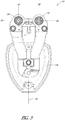
- the first blade 18 When viewed from the distal end of the retractor 10 (shown in FIG. 4 ).
- the first blade 18 can translate a first distance to the left of the third blade 46.
- the second blade 38 can translate a second distance to the right of the third blade 46.
- the first distance can be equal to the second distance, but need not be.
- the configuration of the rails 66, 68 permits the first blade 18 to translate relative to the second blade 38 without interference of the rails 66, 68.
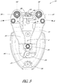
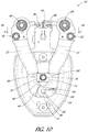
- FIG. 5 shows the top view of the retractor 10.
- the proximal ends 24, 44 of the arms 12, 32 can be coupled to the body 26.
- the arms 12, 32 are coupled to the body 26 at the pivot 72.
- the retractor 10 can include an actuator 74.
- the actuator 74 interacts with the arms 12, 32 to spread the arms 12, 32.
- One embodiment of the actuator is shown in FIG. 10 . Depression of the actuator 74, in the direction of the arrow A in FIG. 5 (i.e., into the page) results in the arms 12, 32 and therefore the blade assemblies 16, 36 moving apart along the directional arrows B and C, causing retractor 10 to assume the opened position depicted in FIG. 5 .
- the third axis 56 forms an arc due in part to the pivot 72.
- the first blade 18 will follow an arced path away from the third blade 46.
- the second blade 38 will follow an arced path away from the third blade 46.
- the first blade 18 will follow an arced path in separating from the second blade 38.
- the first blade 18 and the second blade 38 translate when the arms 12, 32 rotate about the pivot 72.
- the third axis 56 can be substantially perpendicular or perpendicular to the first axis 52 and the second axis 54.
- the third axis 56 can extend perpendicularly or substantially perpendicularly through the first axis 52 and the second axis 54.
- the retractor 10 comprises a pair of arms 12 and 32 connected via a pivot 72.
- an actuator may be used.
- scissor-like actuators are known in the clamp and retractor arts.
- the actuator comprises a pair of handles (not shown) coupled to the arms 12 and 32.
- the handles can be roughly parallel and joined together at a pivot point 72.
- the handles can be crossed (e.g. scissor-like) handles and joined together at a pivot point 72.
- the actuator is a scissor-like embodiment, the motion of blade assemblies 16 and 36 traverse an arc rather than a straight line upon opening of the retractor 10.
- the spatial relationship of the two blade assemblies 16 and 36 can be conceptualized as changing along a line described by arrows B and C, which for the purpose of brevity is referred to herein as an axis, and in particular the third axis 56.
- While the illustrated embodiment uses a mechanism for moving the first blade 18 to the second blade 38 comprising a pair of arms 12, 32 joined to one another at a pivot 72, other configurations are contemplated.
- the proximal ends 24, 44 of the arms 12, 32 can be joined in alternative ways to the body 26 such that the movement of the arms 12, 32 is not a pivoting motion about pivot 72.
- arms 12, 32 can be joined one to another by a cross member (not shown). The cross member holds the arms 12, 32 in parallel and stabilizes the arms 12, 32.
- One or more arms 12, 32 can be moved along the cross member in order to translate the first blade 18 away from the third blade 46 and to translate the second blade 38 away from the third blade 46.
- the first arm 12 linearly translates relative to the second arm 32, rather the rotating about the pivot 72.
- the third axis 56 defines a geometric line passing through and joining the first axis 52 and the second axis 54.
- the first blade 18 follows a straight path away from the second blade 38.
- the retractor described herein possesses a device for locking the arms 12, 32 in at least one predetermined position along the third axis 56.
- the device for locking the arms 12, 32 can be a ratchet (not shown).
- the device for locking the arms 12, 32 can be a detent and recess configuration.
- the device for locking the arms 12, 32 can be disposed on the pivot 72 or the cross member (not shown).
- the arms 12, 32 may be removed from the body 26.
- the pivot 72 can be removed to remove the arms 12, 32 from the body 26. This may occur at any time, e.g. prior to or during sterilization of the retractor 10 or during a surgical procedure once the retractor 10 has been opened. Removal of the body 26 during surgery may afford a member of the surgical team greater freedom of motion, an improved field of view or both.
- Insertion of the blades 18, 38, 46 into an incision in the closed position (as in FIGS. 1-3 ) and translating the first blade 18 and the second blade 38 to an opened position (as in FIGS. 4-5 ) results in a stretching of the incision along the third axis.
- This stretching increases the length of the incision from a length approximately equal to the length L of a single blade (e.g., the first blade 18) to a length L' greater than the length L of a single blade (e.g., the first blade 18).
- the retractor 10 is in the opened position, meaning that the first blade 18 is relatively separated from the second blade 38 along the third axis 56.
- the blade assembly 16 moves along the directional arrow B and blade assembly 36 moves along the directional arrow C, they exert force in the direction of lines B and C, respectively.
- the retractor 10 is shown in the "rotated position,” meaning that the first blade 18 is rotated relative to the third blade 46 and/or the second blade 38 is rotated relative to the third blade 46 and/or rotated with respect to the third blade 46 in a first position. While the application uses the phrase "the rotated position,” it is understood that one or more positions may be described as rotated.
- the first blade 18 can be rotated at any angle relative to the third blade 46 greater than zero (e.g., 5°, 10°, 15°, 20°, 25°, 30°, 35°, 40°, 45°, 50°, 55°, 60°, 65°, 70°, 75°, 80°, 85°, 90°, 95°, 100°, 105°, 110°, 115°, 120°, 125°, 130°, 135°, 140°, 145°, 150°, 155°, 160°, 165°, 170°, 175°, 180°, between 10-40°, between 20-50°, between 30-60°, between 40-70°, between 50-80°, between 60-90°, between 70-100°, between 80-110°, etc.), the second blade 38 can be rotated at any angle relative to the third blade 46 greater than zero (e.g., 5°, 10°, 15°, 20°, 25°, 30°, 35°, 40°, 45°, 50°, 55°, 60°, 60
- the width W' of the three blades 18, 38, 46 in this configuration is greater than the width W of any one blade, such as the width of the first blade 18 and the rail 64.
- the first blade 18 can rotate in a clockwise direction about the first axis 52.
- the second blade 38 can rotate in a counterclockwise direction about the second axis 54.
- the motion of the first blade 18 can be independent of the motion of the second blade 38. In other embodiments, the motion of the first blade 18 can be coupled to the motion of the second blade 38 such that rotation is controlled by a single rotation mechanism.
- the first blade 18 is rotated by a first rotation mechanism 20 and the second blade 38 is rotated by a second rotation mechanism 40.
- the first blade 18 can rotate in an opposite direction as the second blade 38 such that both blades open relative to the third blade 46.
- the first rotation mechanism 20 can be identical, substantially similar, or a mirror image of the second rotation mechanism 40.
- One embodiment of the first rotation mechanism 20 is shown in FIG. 11-13 .
- Other embodiments are contemplated for rotating the first and/or second blades (e.g., various linkages, hinges and /or cams).
- first rotation mechanism 20 results in rotation of the first blade 18.
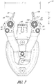
- second rotation mechanism 40 results in rotation of the second blade 38, respectively, as depicted in FIG. 7 .
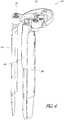
- rotating the first blade 18 causes the first blade 18 to exert force in the direction of direction arrow F
- rotating the second blade 38 causes the second blade 38 to exert force in the direction of direction arrow G.
- the first axis 52 and second axis 54 may be substantially coplanar with one another. Indeed in some embodiments, the first axis 52 and second axis 54 are not only coplanar but also substantially parallel to one another. In particular embodiments, the first axis 52 and second axis 54 are coplanar with, parallel to, or at some pre-determined skew angle with respect to one another.
- the first blade 18 is rotated and/or the second blade 38 is rotated after the first blade 18 is translated relative to the third blade 46 and the second blade 38 is translated relative to the third blade 46.
- the retractor 10 is opened by the first blade 18 and the second blade 38 translating relative to the third blade 46 along the third axis 56 to achieve the opened position.
- the first blade 18 is rotated relative to the third blade 46 about the first axis 52 and/or the second blade 38 is rotated about the second axis 54 relative to the third blade 46 to achieve the rotated position.
- the first blade 18 and/or the second blade 38 is rotated before the first blade 18 is translated relative to the third blade 46 and the second blade 38 is translated relative to the third blade 46.
- the first blade 18 is rotated about the first axis 52 relative to the third blade 46 and/or the second blade 38 is rotated the second axis 54 relative to the third blade 46 to achieve the rotated position.
- the retractor 10 is opened by the first blade 18 and the second blade 38 translating relative to the third blade 46 along the third axis 56 to achieve the opened position.
- the first blade 18 and/or the second blade 38 is rotated again relative to the third blade 46 to achieve the rotated position (e.g., another rotated position within the broad definition of the "rotated position").
- the rotated position creates and maintains an aperture in the incised tissue that is wider W' (i.e. dimensionally larger in a direction perpendicular or oblique to the direction of the incision) than the incision.
- W' i.e. dimensionally larger in a direction perpendicular or oblique to the direction of the incision
- the retractor 10 creates and maintains an aperture in the incised tissue that is both longer L' due to the translation (i.e. dimensionally larger in the direction of the incision,) and wider W' due to the rotation (i.e. dimensionally larger in a direction perpendicular or oblique to the direction of the incision) than the incision.
- the incision is a straight line incision of about 0.1 to about 3 inches in length
- it can apply to any shape of incision (e.g. an arc, a sinusoid, etc.) of any length.
- the contemplated size of the incision is about 0.5 to 2 inches in length and the blades 18, 38, 46 are appropriately sized so that when the retractor 10 is in the closed position the blade blades 18, 38, 46 fit lengthwise within the incision without requiring substantial stretching of the incised tissue prior to opening of the retractor 10.
- the blades 18, 38, 46 are sized to snugly fit within the incision when the retractor 10 is in the closed position.
- the retractor 10 is shown in the "pivoted position,” meaning that the first blade 18 is pivoted relative to the third blade 46 and/or the second blade 38 is pivoted relative to the third blade 46. While the application uses the phrase “the pivoted position,” it is understood that one or more positions may be described as pivoted.
- the first blade 18 can be pivoted at any angle relative to the third blade 46 greater than zero (e.g., 5°, 10°, 15°, 20°, 25°, 30°, 35°, 40°, 45°, 50°, 55°, 60°, 65°, 70°, 75°, 80°, 85°, 90°, 95°, 100°, 105°, 110°, 115°, 120°, 125°, 130°, 135°, 140°, 145°, 150°, 155°, 160°, 165°, 170°, 175°, 180°, between 10-40°, between 20-50°, between 30-60°, between 40-70°, between 50-80°, between 60-90°, between 70-100°, between 80-110°, etc.), the second blade 38 can be pivoted at any angle relative to the third blade 46 greater than zero (e.g., 5°, 10°, 15°, 20°, 25°, 30°, 35°, 40°, 45°, 50°, 55°, 60°, 60
- the width W" of the three blades 18, 38, 46 in this configuration is greater than the width W of any one blade, such as the width of the first blade 18 and the rail 64.
- the length L" of the three blades 18, 38, 46 in this configuration is greater than the length L of any one blade, such as the length of the first blade 18.
- the first blade 18 can pivot in a clockwise direction about the fourth axis 58.
- the second blade 38 can pivot in a counterclockwise direction about the fifth axis 60.
- the motion of the first blade 18 can be independent of the motion of the second blade 38. In other embodiments, the motion of the first blade 18 can be coupled to the motion of the second blade 38 such that pivoting is controlled by a single pivot mechanism.
- the pivoted position creates and maintains an aperture in the incised tissue that is both longer L" (i.e. dimensionally larger in the direction of the incision,) and wider W" (i.e. dimensionally larger in a direction perpendicular or oblique to the direction of the incision) than the incision.
- the fourth axis 58 is perpendicular to the first axis 52.
- the first blade 18 can rotate about the first axis 52 and pivot about the fourth axis 58. This provides at least two degrees of freedom for the first blade 18 and allows the first blade 18 to be positioned in a variety of locations within the incision.
- the fifth axis 60 is perpendicular to the second axis 54.
- the second blade 38 can rotate about the second axis 54 and pivot about the fifth axis 60. This provides at least two degrees of freedom for the second blade 38 and allows the second blade 38 to be positioned in a variety of locations within the incision.
- the fourth axis 58 and the fifth axis 60 are perpendicular to the third axis 56. The movement along the third axis 56 provides an extra degree of freedom.
- the first blade 18 is pivoted by a first pivot mechanism 22 and the second blade 38 is pivoted by a second pivot mechanism 42.
- the first blade 18 can pivot in an opposite direction as the second blade 38 such that both blades open relative to the third blade 46.
- the first pivot mechanism 22 can be identical, substantially similar, or a mirror image of the second pivot mechanism 42.
- One embodiment of the first pivot mechanism 22 is shown in in FIGS. 14-15 .
- Other embodiments are contemplated for providing the described pivoting motions such as, for example, various linkages, cams and/or hinges.
- Pivoting the first pivot mechanism 22 about the fourth axis 58 in the direction of adjustment arrow H results in rotation of the first blade 18.
- Turning the second pivot mechanism 42 about the fifth axis 60 in the direction of adjustment arrow I results in rotation of the second blade 38, respectively, as depicted in FIG. 9 .
- Pivoting the first blade 18 causes the first blade 18 to exert force in the direction of direction arrow J
- pivoting the second blade 38 causes the second blade 38 to exert force in the direction of direction arrow K.
- the first axis 52 is substantially perpendicular or perpendicular to the fourth axis 58. In particular embodiments, the first axis 52 is at some pre-determined skew angle with respect to the fourth axis 58.
- the second axis 54 is substantially perpendicular or perpendicular to the fifth axis 60. In particular embodiments, the second axis 54 is at some pre-determined skew angle with respect the fifth axis 60.
- the third axis 56 is substantially perpendicular or perpendicular to the fourth axis 58, the fifth axis 60 or both the fourth axis 58 and the fifth axis 60.
- the third axis 56 is substantially perpendicular or perpendicular to both the fourth axis 58 and the fifth axis 60. In some embodiments, the third axis 56 is perpendicular or substantially perpendicular to the fourth axis 58, the fifth axis 60 or both the fourth axis 58 and the fifth axis 60. In some embodiments, the third axis 56 is perpendicular or substantially perpendicular to both the fourth axis 58 and the fifth axis 60.
- the third blade 46 can be pivoted about a seventh axis (not shown) that is parallel to the third axis 56 and extends from near the connection between the third blade 46 and the body 26.
- the connector 28 can have a hinge that pivots the third blade 46.
- the third blade 46 can be pivoted at any angle relative to the vertical plane greater than zero (e.g., 5°, 10°, 15°, 20°, 25°, 30°, 35°, 40°, 45°, 50°, 55°, 60°, 65°, 70°, 75°, 80°, 85°, 90°, 95°, 100°, 105°, 110°, 115°, 120°, 125°, 130°, 135°, 140°, 145°, 150°, 155°, 160°, 165°, 170°, 175°, 180°, between 10-40°, between 20-50°, between 30-60°, between 40-70°, between 50-80°, between 60-90°, between 70-100°, between 80-110°, etc.).
- zero e.g., 5°, 10°, 15°, 20°, 25°, 30°, 35°, 40°, 45°, 50°, 55°, 60°, 65°, 70°, 75°, 80°, 85°, 90°, 95
- the third blade 46 can be pivoted a same angle or a different angle as the first blade 18 and/or second blade 38, wherein the length L" and/or the width W" in the pivoted position is greater than the incision length or width or the length or width of any of the blades 18, 38, 46, or other pivoted positions.
- the seventh axis is described in some embodiments as substantially parallel or parallel to the third axis 56. In other embodiments, the seventh axis can be at some pre-determined skew angle with respect to the third axis 56.
- the width W" of the three blades 18, 38, 46 in this configuration is greater than the width W of any one blade, such as the width of the third blade 46.
- the length L" of the three blades 18, 38, 46 in this configuration is greater than the length L of any one blade, such as the length of the third blade 46.
- the first blade 18 can pivot in a clockwise direction about the fourth axis 58.
- the second blade 38 can pivot in a counterclockwise direction about the fifth axis 60.
- the third blade 46 can pivot about the seventh axis toward the proximal direction.
- the motion of the third blade 46 can be independent of the motion of the first blade 18 and the second blade 38.
- the motion of the third blade 46 can be coupled to the motion of the first blade 18 and/or the second blade 38 such that pivoting is controlled by a single pivot mechanism.
- the pivoted position creates and maintains an aperture in the incised tissue that is both longer L" (i.e. dimensionally larger in the direction of the incision,) and wider W" (i.e. dimensionally larger in a direction perpendicular or oblique to the direction of the incision) than the incision.
- the third blade 46 can be pivoted by a pivot mechanism that is identical or substantially similar to the pivot mechanism described herein for the first blade 18 and second blade 38.
- Other embodiments are contemplated for providing the described pivoting motions such as, for example, various linkages, cams, hinges, gears and/or levers.
- the first blade 18 is pivoted and/or the second blade 38 is pivoted after the first blade 18 is rotated and/or the second blade 38 is rotated and after the first blade 18 is translated relative to the third blade 46 and the second blade 38 is translated relative to the third blade 46.
- the retractor 10 is opened by the first blade 18 and the second blade 38 translating along the third axis 56 relative to the third blade 46 to achieve the opened position.
- the first blade 18 is rotated about the first axis 52 relative to the third blade 46 and/or the second blade 38 is rotated about the second axis 54 relative to the third blade 46 to achieve the rotated position.
- the first blade 18 is pivoted about the fourth axis 58 relative to the third blade 46 and/or the second blade 38 is pivoted about the fifth axis 60 relative to the third blade 46 to achieve the pivoted position.
- the third blade 46 is pivoted about the third axis 56 toward the proximal direction. However, this depicts only some methods of use.
- first blade 18 is pivoted and/or the second blade 38 is pivoted and/or the third blade 46 is pivoted before the first blade 18 and/or the second blade 38 is rotated. In some methods, the first blade 18 is pivoted and/or the second blade 38 and/or the third blade 46 is pivoted is pivoted before the first blade 18 is translated relative to the third blade 46 and the second blade 38 is translated relative to the third blade 46.
- FIGS. 10-15 show embodiments of the actuator 74, the rotation mechanism 20, and the pivot mechanism 22.
- the actuator 74 is a device for translating the first blade 18 and the second blade 38 about the third axis 56.
- the rotation mechanism 20 is a device for rotating the first blade 18 about the first axis 52.
- the rotation mechanism 40 can be identical, substantially similar or a mirror image of the rotation mechanism 20.
- the pivot mechanism 22 is a device for pivoting the first blade 18 about the fourth axis 58.
- the pivot mechanism 42 can be identical, substantially similar or a mirror image of the pivot mechanism 22.
- Other configurations are possible for rotating the blades as described herein e.g., various levers, knobs, cams, etc.
- FIG. 10 shows one embodiment of the actuator 74.
- the actuator 74 comprises a screw 76.
- the screw 76 can be configured to mate with a washer (not shown) in the body 26.
- the washer allows the screw 76 to rotate without translation (e.g., rotate in place).
- the actuator 74 comprises a block 78.
- the block 78 has a through lumen 80.
- the through lumen 80 is threaded.
- the through lumen 80 is not threaded.
- the through lumen 80 is sized to accept the screw 76.
- the through lumen 80 can include a counter sunk opening sized to accept the head of the screw 76.
- the first arm 12 has a first mating surface 82 and the second arm 32 has a second mating surface 84.
- the mating surfaces 82, 84 interact with the side surfaces of the block 78.
- the mating surfaces 82, 84 are ramped or angled inward and the side surfaces of the block 78 are flat.
- the mating surfaces 82, 84 are flat and the side surfaces of the block 78 are ramped or angled inward.
- the pivot 72 can include a pivot post 86.
- the pivot post 86 extends along a longitudinal axis.
- the proximal end 24 of the first arm 12 has a first connecting hole 88 sized to accept the pivot post 86 and the proximal end 44 of the second arm 32 has a second connecting hole (not shown) sized to accept the pivot post 86.
- the first arm 12 and the second arm 32 rotate about the longitudinal axis of the pivot post 86.
- the first arm 12 rotates clockwise and the second arm 32 rotates counterclockwise about the longitudinal axis of the pivot post 86. This causes the first blade assembly 16 and the second blade assembly 36 to generally translate along a third axis 56.
- the retractor 10 can include a spring 94.
- the spring 94 wraps around the pivot post 86.
- the first connecting hole 88 and/or the second connecting hole are sized to accept a portion of the spring 94, for instance the portion of the spring that is wrapped around the pivot post 86.
- the spring 94 biases the first arm 12 and the second arm 32 in the closed position.
- the actuator 74 overcomes this biasing force to pivot the first arm 12 and the second arm 32 about pivot 72, which causes the first blade assembly 16 and the second blade assembly 36 to generally translate along a third axis 56.
- the spring 94 tends to bias the arms 12 and 32 together.
- the spring 94 biases the first arm 12 and the second arm 32 apart. This biasing force decreases the force needed by the actuator 74 to translate the first blade assembly 16 and the second blade assembly 36 along the third axis 56.
- FIGS. 11-12 are perspective views of the second blade 38 in the closed position and the rotated position, respectively.
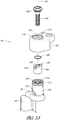
- FIG. 13 is an exploded view of the rotation mechanism 40.
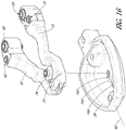
- FIGS. 1 , 6-7 depict an embodiment of a second blade assembly 38, which comprises the second blade 38.
- the second blade assembly 36 comprises a hub 98.
- the hub 98 is coupled to the distal end 34 of the second arm 32.
- the hub 98 houses both the rotation mechanism 40 and the pivot mechanism 42.
- the second axis 54 to achieve the rotated position.
- the second blade 38 is adapted to rotate about the second axis 54.
- FIG. 6 shows a perspective view of the retractor 10 with the first blade 18 and the second blade 38 in a rotated position.
- FIG. 7 shows a top view of FIG. 6 .
- the hub 98 can have a first connecting hole 100.
- the first connecting hole 100 can be non-threaded.
- the hub 98 is coupled to an inner barrel 102.
- the inner barrel 102 is integrally formed with the second blade 38.
- the inner barrel 102 can be coupled with the second blade 38.
- the second blade 38 can be connected to the second bridge 96 which can be connected to the inner barrel 102.
- the inner barrel 102 can be sized to be accepted within the first connecting hole 100 of the hub 98.
- the second rotation mechanism 40 can include a screw 104.
- the second rotation mechanism 40 can include a collar 106.
- the collar 106 can include a threaded bore 108 sized to receive the screw 104.
- the screw 104 and the collar 106 are sized to be received in a lumen 110 of the inner barrel 102.
- the inner barrel 102 can have a first slot 112 and a second slot 114 cut into the upper portion 116 of the inner barrel 102.
- the first slot 112 can be offset 180 degrees from the second slot 114.
- the upper portion 116 of the inner barrel 102 is that portion of the inner barrel 102 above the highest point at which the second bridge 96 connects to the inner barrel 102.
- the first slot 112 and second slot 114 can extend from near the top of the inner barrel 102 to the bottom of the inner barrel 102.
- the slots 112, 114 extend diagonally across the upper portion 116. Although two slots 112, 114 are shown, other configurations are contemplated (e.g., one slot, three slots, four slots, five slots).
- the one or more slots may have the same slope and extend in the same direction.
- the inner barrel 102 can have an engagement groove 118 circumscribing the inner barrel 102 above the slots 112, 114.
- the hub 98 can have a complementary engagement groove 120 circumscribing the connecting hole 100.
- An appropriately sized retention member such as an o-ring can be received within the grooves 118, 120. The retention member allows the inner barrel 102 to rotate but not translate within the first connecting hole 100.
- the lumen 110 can have an engagement groove 124 circumscribing the lumen 110 above the slots 112, 114.
- the screw 104 can have a complementary engagement groove 126 circumscribing the head of the screw 104.
- An appropriately sized retention member 128 such as an o-ring can be received within the grooves 124, 126. The retention member 128 allows the screw 104 to rotate but not translate within the inner barrel 102.
- FIGS. 11-13 further depict a first connector pin 134 and second connector pin 136.
- the number of pins equals the number of slots.
- the connector pins 134, 136 extend outward from the collar 106.
- the first connector pin 134 is offset 180 degrees from the second connector pin 136.
- Other configurations are contemplated.
- the first connector pin 134 is sized to extend through the first slot 112 and the second connector pin 136 is sized to extend through the second slot 114.
- the screw 104 fits within the threaded bore 108 of the collar 106, as depicted in FIGS. 11-12 .
- the first slot 112 forms a passage through which the first connector pin 134 fits.
- the second slot 114 forms a passage through which the second connector pin 136 fits.
- the second blade 38 can be in the closed position when the first connector pin 134 is at the bottom of the first slot 112 and the second connector pin 136 is at the bottom of the second slot 114.
- FIG. 4 it is seen that the second blade 38, and the third blade 46 stack to form a substantially planar blade set.
- the retention member 128 prevents the screw 104 from translating.
- the connector pins 134, 136 can be rigidly coupled to the collar 106. At least one connector pin 134 or 136 can be retained in the channel 122 of the hub 98, which prevents the collar 106 from rotating. Rotating the screw 104 will force the collar 106 to rise since the screw 104 cannot translate and the collar 106 cannot rotate.
- the connector pins 134, 136 will similarly rise with the collar 106. As the connector pins 134, 136 rise, they act upon the slots 112, 114.
- the inner barrel 102 will rotate as the connector pins 134, 136 rise. Rotation of the inner barrel 102 also rotates the second blade 38. In other words, rotating the screw 104 forces the connector pins 134, 136 to rise and act upon the slots 112, 114, thereby causing the inner barrel 102 to rotate, and also rotate the second blade 38 about the second axis 54.
- the first blade 18 can be rotated in the other direction (e.g., counterclockwise to close the first blade 18).
- the assembly of inner barrel 102, the collar 106, the screw 104, and the connector pins 134, 136 fits through the first connecting hole 100 of the hub 98.
- the head of the screw 104 is visible through the hub 98 allowing the screw 104 to be manipulated.
- the connector pins 134, 136 engage the slots 112, 114, thereby permitting the inner barrel 102 to freely turn about the second axis 54.
- the retention member (not shown) prevents the inner barrel 102 from moving up or down along the second axis 54.
- the retention member 128 can prevent the screw 104 from moving up or down along the second axis 54.
- Turning the screw 104 about the second axis 54 in one direction can cause the collar 106 to move upward along the second axis 54, while turning the screw 104 in the opposite direction can cause the collar 106 to move downward along the second axis 54.
- movement of the collar 106 forces movement of the connector pins 134, 136 up and down the second axis 54. Movement of the connector pins 134, 136 in one direction can create force in one direction on the slots 112, 114 in the inner barrel 102 causing the inner barrel 102 to rotate.
- the screw 104 can be turned to rotate the second blade 38 toward or away from the third blade 46.
- the second blade 38 is connected to a second bridge 96, which in turn is connected to the inner barrel 102 such that rotating the inner barrel 102 about second axis 54 clockwise can result in the second blade 38 also turning to clockwise.
- the first blade assembly 16 can be substantially similar to the embodiment described herein.
- the first blade assembly 16 can include an inner barrel similar to inner barrel 102, screw similar to screw 104, collar similar to collar 106, and connecting pins similar to connecting pins 134, 136.
- the first blade assembly 16 rotates clockwise about the first axis 52 away from the third blade 46 and the second blade assembly 36 rotates counterclockwise about the second axis 54 away from the third blade 46.
- the inner barrel of the second blade assembly 36 can be a mirror image of the first blade assembly 16.
- the first blade assembly 16 can have one slot which is the mirror image of first slot 112 and another slot which is the mirror image of second slot 114. This slot configuration allows the first blade 18 to rotate clockwise, the opposite direction as the second blade 38 described herein.
- the function of the connector pins of the first blade assembly 16 and the method of rotation can be substantially similar.
- FIG. 14 is a perspective view of the first blade assembly 16 in the pivoted position.
- FIG. 15 is an exploded view of the pivot mechanism 22.
- FIGS. 8-9 depict an embodiment of a first blade assembly 16, which comprises the first blade 18.
- the first blade assembly 16 comprises the hub 97.
- the hub 97 can be similar, identical or a mirror image of the hub 98 described with respect to FIGS. 11-13 .
- the hub 97 is coupled to the distal end 14 of the first arm 12.
- the hub 97 houses both the rotation mechanism 20 and the pivot mechanism 22.
- the hub 97 can have a second connecting hole 142 and a third connecting hole 144.
- the second connecting hole 142 can be non-threaded.
- the third connecting hole 144 can be threaded.
- the distal end 14 of the first arm 12 can include a post 146.
- the post 146 can be accepted into a bore (not shown) of the hub 97.
- the post 146 of the first arm 12 and the bore of the hub 97 interact to couple the first arm 12 to the first blade assembly 16.
- the post 146 has a round cross-section but other shapes are contemplated.
- the post 146 has a groove 150 circumscribing post 146.
- the groove 150 is along the distal end of the post 146 that extends into the bore.
- the second connecting hole 142 is sized to accept a pin 152.
- the upper portion of the pin 152 fits within the second connecting hole 142.
- the lower portion of the pin 142 fits within the groove 150 of the post 146.
- the distal end 14 of the first arm 12 can include a ledge 154.
- the ledge 154 can be adjacent to a surface of the hub 98. Unlike the post 146, the ledge 154 is not accepted into the hub 98.
- the ledge 154 has a substantially square cross-section but other shapes are contemplated.
- the first pivot mechanism 22 can include a screw 156.
- the screw 156 is accepted into the third connecting hole 144 which is threaded.
- the bottom portion of the screw 156 abuts the ledge 154.
- the ledge 154 prevents the screw 156 from translating when the screw 156 is rotated.
- the second blade assembly 36 can be similar to the embodiments described herein.
- the second blade assembly can include a post similar to post 146, a pin similar to pin 152, and a screw similar to screw 156.
- the first blade assembly 16 rotates counterclockwise about the post 146 and the second blade assembly 36 rotates clockwise about a similar post.
- the second blade assembly 36 can be a mirror image of the first blade assembly 16.
- the second connecting hole of the second blade assembly 36 can be closer to the third blade 46 and the third connecting hole of the second blade assembly 36 can be further away from the third blade 46.
- These configurations of the connecting holes allow the second blade 38 to pivot in the opposite direction as the first blade 18 described herein.
- the function of the pins and the posts of the second blade assembly 36 and the method of rotation of the screw can be similar.
- the retractor 10 can be in the "slid position,” meaning that the first arm 12 and the second arm 32 are displaced in the proximal-distal direction relative to the third blade 46 along a sixth axis 62. While the application uses the phrase "the slid position,” it is understood that one or more positions may be described as slid. For instance, the first arm 12 can be slid at any position along the body 26, the second arm 32 can be slid at any position along the body 26, the first arm 12 can be slid approximately the same distance as the second arm 32, wherein the width in the slid position is greater than the incision width or the width of any of the blades 18, 38, 46, or other slid positions.
- FIG. 16 depicts an embodiment of a slide mechanism 162 that provides an additionally degree of freedom.
- the slide mechanism 162 can include a carriage 164.
- the carriage 164 can be attached to the body 26 via a track 166.
- the track 166 can be linear and/or parallel to the width of the blades 18, 38, 46.
- the track 166 can extend from the proximal end of body 26 to the distal end of the body 26, or over a portion therewithin.
- the first arm 12 and the second arm 32 can be coupled to the carriage 164.
- the pivot 72 can be coupled to the carriage 164.
- the slide mechanism 162 can include an actuator (not shown) that permits the carriage 164 to slide along the track 166.
- the track 166 can define the sixth axis 62.
- the actuator can include a screw that abuts a proximal end of the carriage 164. Rotation of the actuator causes the carriage 164 to translate from the proximal end of the body 26 to the distal end of the body 26 along the sixth axis 62.
- the slide mechanism 162 permits the arms 12, 32 to extend a greater distance from the distal end of the body 26.
- the slide mechanism 162 permits the first blade 18 and the second blade 38 to slide relative to the third blade 46.
- the third blade 46 is not coupled to the sliding mechanism, but is coupled to the body 26 described herein. This permits the first blade 18 and the second blade 38 to slide relative to the third blade 46.
- the slide mechanism 162 permits the incision to be stretched along the width of the incision to create an opening width greater than width W".
- slide mechanism 162 causes the first arm 12 and the second arm 32 to slide relative to the body 26. Sliding the first arm 12 and the second arm 32 will also slide the first blade 18 and the second blade 38.
- the pivot 72 can be received within the carriage 164, allowing the arms 12, 32 to move about the pivot 72 and allow the blade assemblies 16, 36 to translate along the third axis 56.
- the actuator 74 can translate the blades 18, 38 irrespective of the location of the carriage 164.
- the rotation mechanisms 20, 40 can rotate the blades 18, 38 irrespective of the location of the carriage 164.
- the pivot mechanisms 22, 42 can pivot the blades 18, 38 irrespective of the location of the carriage 164.
- the carriage 164 can slide in either direction.
- the third blade 46 can be coupled to the carriage 164 and can be movable relative to the arms 12, 32, which can be coupled to the body 26. Rotation of the actuator can cause the carriage 164 to translate from the distal end of the body 26 to the proximal end of the body 26 along the sixth axis 62.
- the slide mechanism 162 permits the third blade 46 to move a distance toward the proximal end of the body 26, permitting the incision to be stretched along the width of the incision to create an opening width greater than width W".
- the pivot mechanism of the third blade 46 can pivot the third blade 46 irrespective of the location of the carriage 164.
- the carriage 164 can slide in either proximal or distal directions.
- kits comprising a retractor 10.
- the kit comprises a plurality of removable and exchangeable blade assemblies 16, 36. Each blade assembly may comprise a different actuator, a different rotation mechanism, a different pivot mechanism and/or a different slide mechanism. Each blade assembly may comprise a different blade.
- the kit comprises at least three blade assemblies having amongst the three blade assemblies at least two distinct blade configurations. In other embodiments, the kit comprises from 3 to 12 blade assemblies having amongst the several blade assemblies from 2 to 12 distinct blade configurations.
- the kit comprises at least two pairs of identical, substantially similar, or mirror image blade assemblies. In some embodiments, the kit comprises at least two pairs of mirror image blade assemblies. In other embodiments, the kit comprises from 2 to 10, especially about 2 to 5 such pairs of blade assemblies.
- the retractor 10 may be provided to a surgeon or surgical personnel in the form of a kit comprising additional surgical articles and optionally instructions for the use and handling of the retractor.
- additional surgical articles may include one or more of: scalpels, suture needles, pedicle screws, suture material, spinal implant material, spinal fusion rods, biocompatible adhesive and closure staples.
- the blades 18, 38, 46 are removable. In some embodiments, the blades 18, 38, 46 may take on a variety of shapes and sizes. In some embodiments, a kit is provided comprising a plurality of retractors having blades of various sizes, shapes or both. In some embodiments, a kit is provided comprising one or more arms and two or more blade assemblies (optionally of varying blade sizes and/or shapes). In some embodiments, a kit is provided comprising a retractor, optionally more than two blades assemblies, at least two of which differ from one another in size, shape or both, and one or more pedicle screws for performing lumbar surgery. Thus, a variety of surgical kits for performing surgery, especially back surgery, are contemplated and methods of using the retractor to perform surgery, especially back surgery, are contemplated
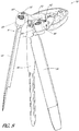
- FIGS. 17A-17D illustrate a probe 400 and a method for its use in conjunction with the retractor 10.
- FIG. 17A illustrates a probe 400 and a portion of a spine, including a first vertebra 440, a second vertebra 450, and a disc 460 disposed between the first vertebra 440 and the second vertebra 450.
- the probe 400 can have a probe body 410, a proximal end 413, a distal end 412, an anchor tip 430, and a distal shoulder 420.
- the anchor tip 430 can be disposed at the distal end 412 of the probe body 410.
- the distal shoulders 420 can be located at the distal end 412 of the probe 400 at the base of the anchor tip 430.
- the probe 400 can have a distal end of a different shape.
- the distal end 412 can be formed without the shoulder 420 and/or without the tip 430 and/or one of both elements can be modified in shape.
- the probe 400 can be rectangular in horizontal cross section (i.e., the plane bisecting the probe 400 perpendicular to the axis formed by the proximal end 413 and the distal end 412). In other embodiments, the probe 400 can be circular in horizontal cross section or oval cross section.
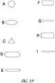
- FIG. 19A-19I illustrate some representative cross sectional shape the probe 400 can have, including: a circle (shown in FIG. 19A ); an oval (shown in FIG. 19B ); a triangle (shown in FIG. 19C ); a flattened oval (shown in FIG. 19D ); a thin flattened oval (shown in FIG. 19E ); a rounded rectangle (shown in FIG.
- the probe 400 can be any other appropriate shape, including but not limited to square, triangular, and ellipsoid.
- a rectangular cross-sectional shape can include a shape in which the corners of the device are rounded and/or arrangements in which the adjacent sides are not exactly perpendicular (e.g., plus or minus 10 degrees, 5 degrees, 1 degrees or .1 degrees from perpendicular) and/or when the sides of the probe have ridges, bends that deviate 10%, 5%, 1% or .1% from the width or length of a side.
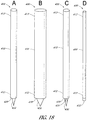
- FIG. 18A and 18B illustrate a probe 400 with circular cross section and a probe 400 with an oval cross section respectively.
- the probe 400 can be constructed out of a biocompatible metal, such as but not limited to stainless steel, titanium, and cobalt chrome moly. In other embodiments, the probe 400 can be constructed out of a biocompatible ceramic. In still other embodiments, the probe 400 can be constructed out of any stiff, biocompatible material, including such classes of materials as metals, ceramics, and polymers, or any combinations thereof.
- the probe 400 can have a vertical length (i.e., length from the distal end 412 to the proximal end 413) in the range of about 5-50cm, about 6-40cm, about 7-30cm, about 7-20cm and about 8-10cm or any other range which is appropriate to allow the probe 400 to function as desired.
- the probe 400 can have a width in its largest, non-vertical dimension, in the range of about 5mm-5cm, about 6mm-4cm, about 7mm-3cm, and about 8mm-2cm, including about 1.5cm.
- the distal shoulders 420 can extend horizontally in from the edges of the probe 400 in the range of about 0.1-5mm, about 0.2-4mm, about 0.3-3mm, about 0.4-2mm, about 0.5-1mm, and about 0.6-0.8mm.
- the external corners where the distal shoulders 420 meet the vertical edges of the probe 400 can be squared.
- the external corners where the distal shoulders 420 meet the vertical edges of the probe 400 can be rounded or smoothed.
- the distal shoulders 420 can be machined flat on the bottom (particularly in such embodiments in which the probe 400 is a shape other than rectangular).
- the distal shoulders 420 can be sharpened across their entire length to form a blade along their entire length.
- the distal shoulders can be are sharpened across only a portion of their length to form a blade along only a portion of their length.
- only half of each distal shoulder 420 is sharpened (e.g., either the half of the distal shoulders 420 abutting the anchor tip 430 or the half of the distal shoulders 420 abutting the edges of the probe 400).
- the anchor tip 430 can extend downward from the distal end 412 of the probe 400.
- the anchor tip 430 can be substantially triangular (illustrated in FIG. 17A ).
- the anchor tip 430 can be substantially parabolic.
- the anchor tip 430 can be a small cylindrical member, such as a trocar.
- the anchor tip 430 can be any shape which allows anchoring of the probe 400 in tissue.
- the edges of the anchor tip 430 can be machined to be substantially smooth. In other embodiments, the edges of the anchor tip 430 can be sharpened to form a blade.
- At least a portion of the vertical edges of the probe 400 can be sharpened.
- the portion of the edges of the probe 400 which are sharpened can be disposed near the distal end 412 of the probe 400.
- 1-5cm of the edges of the probe 400 extending up from the distal end 412 and distal shoulders 420 can be sharpened to form a blade to facilitate insertion of the probe 400 into corporeal tissue of a patient.
- the probe 400 can be inserted into a patient, preferably into an anchorable location, such as a collagenous tissue, bone, or vertebral disc.
- FIG. 17A illustrates the probe 400 being inserted into a patient (not fully shown) toward the spine (only a first vertebra 440, second vertebra 450, and disc 460 are illustrated in this representative example).
- the probe 400 illustrated in FIG. 17A is a thin, blade like rectangular probe 400 with a triangular anchor tip 430 and squared corners where the distal shoulders 420 meet the edges of the probe 400.
- the structure of the probe 400 can facilitate its passage through tissues of a patient (e.g., psoas muscles) which can run parallel to the flat surfaces of the probe.
- a physician can select a location in which he desires to use a retractor 10 to form an operative channel in the tissues of the patient (the spine will be used in this example for illustration purposes only).
- a location is preferably selected that provides adequate access to an intervertebral disc space, yet minimizes the risk of injury to the nerves extending from the intervertebral foramen.
- the surgeon selects the location for retractor 10 placement, he can make an incision in the skin and insert the probe 400 by placing the anchor tip 430 against the surface of the patient and applying pressure to the proximal end 413. The physician can then continue to apply pressure, thereby pushing the probe 400 through the tissue of the patient, until the probe 400 is fully in place.
- an imaging modality can be used during the insertion of the probe 400.
- X-ray fluoroscopy can be used during insertion of the probe 400 to ensure correct placement.
- Any appropriate imaging modality can be used to monitor the placement of the probe 400.
- a surgeon can make an incision with another instrument, such as a scalpel, prior to the insertion of the probe 400, into which the probe 400 is inserted.
- a K-wire i.e., guide wire
- the probe 400 can have a passage extending through its longitudinal length to receive the K-wire when the probe 400 is inserted at the surgical location.
- the K-wire advantageously provides improved accuracy in placement of the probe 400 and can also help stabilize the probe 400 during insertion through the patient tissue.
- FIG. 17B illustrates the probe 400 fully in place in a patient.
- the probe 400 has been inserted into the side of the spinal column (here defined by a first vertebra 440, a second vertebra 450, and the disc 460 between them).
- FIG. 17B illustrates the placement of the probe 400 in a location in which the anchor tip 430 can anchor the probe 400.
- the probe 400 has been inserted into the patient until the anchor tip 430 has sunk at least some distance into the disc 460 between the first vertebra 440 and second vertebra 450.
- the anchor tip 430 has sunk into the disc 460 up until the distal shoulders 420 of the probe 400.
- the distal shoulders 420 serve in this example to limit the possible insertion depth of the anchor tip 430 of the probe 400.
- FIG. 17C illustrates the third blade 46 of the retractor 10 (as disclosed herein) and a placed probe 400.
- the third blade 46 can include a longitudinally extending slot 48 sized to accept the probe 40.
- the third blade 46 can fit substantially closely around the probe 400.
- the third blade can be any type of blade as described above, including but not limited to a substantially flat blade.
- An incision I having a length L is made in a suitable tissue, such as the skin overlying or in proximity to the lumbar region of the spine.
- FIG. 17D illustrates the third blade 46 and placed probe 400 of FIG. 17C where the first blade 18 and the second blade 38 of the retractor 10 in their closed configuration have been placed near the third blade 46.
- the blades 18, 38, 46 will be in their stacked configuration when coupled.
- the blades 18, 38, 46 are in the closed position and aligned relatively parallel to one another.
- the connector 50 of the third blade 46 can couple with the connector 28 of the body 26.
- FIG. 17D shows the retractor 10 still in the closed position.
- the retractor 10 of FIG. 17D is manipulated to achieve the opened position, as shown and described in FIGS. 4-5 .
- the incision can be stretched along the length of the incision to pull open the incision.
- translation about the third axis 56 results in the retractor 10 opening: i.e. the first blade 18 and the second blade 38 move apart from one another in the general directions of directional arrows B, C, respectively.
- the incision can be stretched open in the direction of the directional arrows B and C so that it obtains a length L' greater than length L of the incision.
- the retractor 10 of FIG. 17D is manipulated to achieve the rotated position, as shown and described in FIGS. 6-7 .
- the incision can be stretched along the width of the incision.
- the aperture can be opened to a width W'. If the retractor is previously opened as shown in FIG. 4-5 , then the aperture would provide an access area of dimensions L' by W' for surgical personnel to view the operating field, to pass instruments, sutures, implants and other surgical materials through the aperture.
- the retractor 10 of FIG. 17D is manipulated to achieve the pivoted position, as shown and described in FIGS. 8-9 .
- the incision can be stretched along the width and/or length of the incision.
- Turning the pivot mechanism 22, 42 pivots the first blade assembly 16 and second blade assembly 36 in the direction of the arrows H and I about the fourth axis 58 and the fifth axis 60, respectively results in the pivoting of the first blade 18 and the second blade 38, further stretching the incision.
- the aperture can be opened to a length L" and a width W".
- the aperture can provide an access area of dimensions L" by W" for surgical personnel to view the operating field, to pass instruments, sutures, implants and other surgical materials through the aperture.
- the retractor 10 of FIG. 17D is manipulated to achieve the slid position, as shown and described in FIG. 16 .
- the incision can be stretched along the width of the incision.
- Moving the sliding mechanism 162 respectively results in the translation of the arms 12, 32, and therefore the translation of the blades 18, 38, causing the incision to open.
- the aperture A can be opened to a width wider than width W".
- the probe 400 can be removed prior to any of these steps or left in place during the procedure.
- the probe 400 can allow a surgeon to easily and quickly insert a retractor 10 without cutting an incision all the way to the surgery site prior to inserting the retractor 10 into the desired location to access the surgery site. Rather, the surgeon can quickly and easily insert the probe 400 into the desired location, anchor the probe 400 using the anchor tip 430 in the desired location, slip the third blade 46 of the retractor 10 around the probe 400, and then simply slip the retractor 10 into place. From this position, the first blade 18 and/or the second blade 38 can be moved in any of the ways described herein. From this position, the first arm 12 and the second arm 32 can be moved in any of the ways described herein.
- the probe 400 comprises at least one electrode, wherein the at least one electrode is capable of stimulating a nerve to provoke an electromyographic response in the nerve.
- FIG. 18C illustrates a probe 400 with an electrode 431 disposed at the distal end 412 of the probe 400 on the anchor tip 430. In some embodiments, only one electrode is used. In other embodiments, a plurality of electrodes can be used, including about 1-10 electrodes, about 2-8 electrodes, about 3-6 electrodes and about 4-5 electrodes. In some embodiments, at least one electrode can be disposed on the anchor tip 430. In some embodiments, at least one electrode can be disposed on the probe body 410.
- the electrode 431 can be allowed to any of the embodiments described herein.
- the probe 400 comprises an endoscope 499, wherein the endoscope 499 can comprise an imaging element 432 at the distal end 412 of the endoscope 499 as shown in FIG. 18D .
- the endoscope 499 can be configured to both allow a surgeon to visualize the placement of the probe 400 as well as allow a surgeon to slide a retractor 10 down over the probe 400 and into place as described herein to create an operative channel.
- the endoscope 499 can include an anchor tip 430. Such an endoscope can be applied to any of the embodiments described herein.
Landscapes
- Health & Medical Sciences (AREA)
- Life Sciences & Earth Sciences (AREA)
- Surgery (AREA)
- Veterinary Medicine (AREA)
- Engineering & Computer Science (AREA)
- Biomedical Technology (AREA)
- Heart & Thoracic Surgery (AREA)
- Animal Behavior & Ethology (AREA)
- General Health & Medical Sciences (AREA)
- Public Health (AREA)
- Medical Informatics (AREA)
- Molecular Biology (AREA)
- Nuclear Medicine, Radiotherapy & Molecular Imaging (AREA)
- Neurology (AREA)
- Physics & Mathematics (AREA)
- Biophysics (AREA)
- Pathology (AREA)
- Neurosurgery (AREA)
- Orthopedic Medicine & Surgery (AREA)
- Cardiology (AREA)
- Radiology & Medical Imaging (AREA)
- Surgical Instruments (AREA)
- Devices For Conveying Motion By Means Of Endless Flexible Members (AREA)
- Automotive Seat Belt Assembly (AREA)
- Particle Formation And Scattering Control In Inkjet Printers (AREA)
Applications Claiming Priority (3)
| Application Number | Priority Date | Filing Date | Title |
|---|---|---|---|
| US201462048639P | 2014-09-10 | 2014-09-10 | |
| EP15840714.8A EP3190982B1 (fr) | 2014-09-10 | 2015-09-09 | Écarteur |
| PCT/US2015/049211 WO2016040497A1 (fr) | 2014-09-10 | 2015-09-09 | Écarteur |
Related Parent Applications (1)
| Application Number | Title | Priority Date | Filing Date |
|---|---|---|---|
| EP15840714.8A Division EP3190982B1 (fr) | 2014-09-10 | 2015-09-09 | Écarteur |
Publications (1)
| Publication Number | Publication Date |
|---|---|
| EP3733078A1 true EP3733078A1 (fr) | 2020-11-04 |
Family
ID=55459521
Family Applications (2)
| Application Number | Title | Priority Date | Filing Date |
|---|---|---|---|
| EP20180562.9A Withdrawn EP3733078A1 (fr) | 2014-09-10 | 2015-09-09 | Écarteur |
| EP15840714.8A Active EP3190982B1 (fr) | 2014-09-10 | 2015-09-09 | Écarteur |
Family Applications After (1)
| Application Number | Title | Priority Date | Filing Date |
|---|---|---|---|
| EP15840714.8A Active EP3190982B1 (fr) | 2014-09-10 | 2015-09-09 | Écarteur |
Country Status (6)
| Country | Link |
|---|---|
| US (3) | US10426450B2 (fr) |
| EP (2) | EP3733078A1 (fr) |
| JP (2) | JP6957347B2 (fr) |
| AU (3) | AU2015315166B2 (fr) |
| CA (1) | CA2960818A1 (fr) |
| WO (1) | WO2016040497A1 (fr) |
Families Citing this family (45)
| Publication number | Priority date | Publication date | Assignee | Title |
|---|---|---|---|---|
| EP1814474B1 (fr) | 2004-11-24 | 2011-09-14 | Samy Abdou | Dispositifs de placement d'un dispositif orthopedique intervertebral |
| US8142355B2 (en) | 2006-09-25 | 2012-03-27 | Spinal Elements, Inc. | Surgical tissue retractor |
| US8764806B2 (en) | 2009-12-07 | 2014-07-01 | Samy Abdou | Devices and methods for minimally invasive spinal stabilization and instrumentation |
| US8845728B1 (en) | 2011-09-23 | 2014-09-30 | Samy Abdou | Spinal fixation devices and methods of use |
| US20130226240A1 (en) | 2012-02-22 | 2013-08-29 | Samy Abdou | Spinous process fixation devices and methods of use |
| US9198767B2 (en) | 2012-08-28 | 2015-12-01 | Samy Abdou | Devices and methods for spinal stabilization and instrumentation |
| US9320617B2 (en) | 2012-10-22 | 2016-04-26 | Cogent Spine, LLC | Devices and methods for spinal stabilization and instrumentation |
| US9408596B2 (en) | 2013-03-11 | 2016-08-09 | Spinal Elements, Inc. | Method of using a surgical tissue retractor |
| EP3733078A1 (fr) | 2014-09-10 | 2020-11-04 | Spinal Elements, Inc. | Écarteur |
| US10857003B1 (en) | 2015-10-14 | 2020-12-08 | Samy Abdou | Devices and methods for vertebral stabilization |
| EP3426163A4 (fr) * | 2016-03-09 | 2019-12-11 | Spinal Elements Inc. | Écarteur |
| US10420542B2 (en) * | 2016-06-14 | 2019-09-24 | Lsi Solutions, Inc. | Surgical rib retractor |
| US11166709B2 (en) | 2016-08-23 | 2021-11-09 | Stryker European Operations Holdings Llc | Instrumentation and methods for the implantation of spinal implants |
| US10744000B1 (en) | 2016-10-25 | 2020-08-18 | Samy Abdou | Devices and methods for vertebral bone realignment |
| US10973648B1 (en) | 2016-10-25 | 2021-04-13 | Samy Abdou | Devices and methods for vertebral bone realignment |
| US10716553B2 (en) | 2017-04-19 | 2020-07-21 | Pantheon Spinal, Llc | Spine surgery retractor system and related methods |
| US11806250B2 (en) | 2018-02-22 | 2023-11-07 | Warsaw Orthopedic, Inc. | Expandable spinal implant system and method of using same |
| US11134936B2 (en) * | 2018-03-12 | 2021-10-05 | Life Spine, Inc. | Orthopedic retractor for lateral spine surgery |
| US11191532B2 (en) | 2018-03-30 | 2021-12-07 | Stryker European Operations Holdings Llc | Lateral access retractor and core insertion |
| US11179248B2 (en) | 2018-10-02 | 2021-11-23 | Samy Abdou | Devices and methods for spinal implantation |
| US10624623B1 (en) | 2019-02-12 | 2020-04-21 | Edward Rustamzadeh | Lateral retractor system for minimizing muscle damage in spinal surgery |
| US10631842B1 (en) | 2019-02-12 | 2020-04-28 | Edward Rustamzadeh | Lateral retraction system for minimizing muscle damage in spinal surgery |
| US10363023B1 (en) | 2019-02-12 | 2019-07-30 | Edward Rustamzadeh | Lateral retractor system for minimizing muscle damage in spinal surgery |
| US10925593B2 (en) | 2019-02-12 | 2021-02-23 | Edward Rustamzadeh | Lateral retractor system for minimizing muscle damage in spinal surgery |
| US11246582B2 (en) | 2019-02-12 | 2022-02-15 | Edward Rustamzadeh | Dual-motion rotation and retraction system for minimizing muscle damage in spinal surgery |
| US20220031298A2 (en) | 2019-02-12 | 2022-02-03 | Edward Rustamzadeh | Lateral retractor system for minimizing muscle damage in spinal surgery |
| US11517298B2 (en) | 2019-08-14 | 2022-12-06 | Lsi Solutions, Inc. | Surgical rib retractor |
| US11564674B2 (en) | 2019-11-27 | 2023-01-31 | K2M, Inc. | Lateral access system and method of use |
| US11944286B2 (en) | 2020-01-24 | 2024-04-02 | Lsi Solutions, Inc. | Surgical rib retractor |
| US11224415B1 (en) | 2020-07-10 | 2022-01-18 | Warsaw Orthopedic, Inc. | Tissue retractor |
| US11638653B2 (en) | 2020-11-05 | 2023-05-02 | Warsaw Orthopedic, Inc. | Surgery instruments with a movable handle |
| US11963881B2 (en) | 2020-11-05 | 2024-04-23 | Warsaw Orthopedic, Inc. | Expandable inter-body device, system, and method |
| US11291554B1 (en) | 2021-05-03 | 2022-04-05 | Medtronic, Inc. | Unibody dual expanding interbody implant |
| US11517443B2 (en) | 2020-11-05 | 2022-12-06 | Warsaw Orthopedic, Inc. | Dual wedge expandable implant, system and method of use |
| US11564724B2 (en) | 2020-11-05 | 2023-01-31 | Warsaw Orthopedic, Inc. | Expandable inter-body device, system and method |
| US11285014B1 (en) | 2020-11-05 | 2022-03-29 | Warsaw Orthopedic, Inc. | Expandable inter-body device, system, and method |
| US11395743B1 (en) | 2021-05-04 | 2022-07-26 | Warsaw Orthopedic, Inc. | Externally driven expandable interbody and related methods |
| US11833059B2 (en) | 2020-11-05 | 2023-12-05 | Warsaw Orthopedic, Inc. | Expandable inter-body device, expandable plate system, and associated methods |
| US11376134B1 (en) | 2020-11-05 | 2022-07-05 | Warsaw Orthopedic, Inc. | Dual expanding spinal implant, system, and method of use |
| AU2022269077A1 (en) * | 2021-05-07 | 2023-11-30 | Astura Medical Inc. | Spring loaded translating lateral retractor blade |
| CN113413222B (zh) * | 2021-06-22 | 2023-03-28 | 昆明市延安医院 | 一种显微根尖手术用3d打印拉钩 |
| US11612499B2 (en) | 2021-06-24 | 2023-03-28 | Warsaw Orthopedic, Inc. | Expandable interbody implant |
| USD1002842S1 (en) | 2021-06-29 | 2023-10-24 | Edward Rustamzadeh | Combination surgical spinal dilator and retractor system |
| US11730608B2 (en) | 2021-07-13 | 2023-08-22 | Warsaw Orthopedic, Inc. | Monoblock expandable interbody implant |
| US11850163B2 (en) | 2022-02-01 | 2023-12-26 | Warsaw Orthopedic, Inc. | Interbody implant with adjusting shims |
Citations (4)
| Publication number | Priority date | Publication date | Assignee | Title |
|---|---|---|---|---|
| WO2006042241A2 (fr) * | 2004-10-08 | 2006-04-20 | Nuvasive, Inc. | Procedes et systeme d'acces a un site chirurgical |
| US20080077171A1 (en) * | 2006-09-25 | 2008-03-27 | Spinal Elements, Inc. | Retractor |
| US20110224497A1 (en) * | 2010-03-11 | 2011-09-15 | Mark Weiman | Tissue Retractor and Methods Of Use |
| US20120245432A1 (en) * | 2006-06-06 | 2012-09-27 | Edward Karpowicz | Surgical Retractor System |
Family Cites Families (101)
| Publication number | Priority date | Publication date | Assignee | Title |
|---|---|---|---|---|
| US1311313A (en) | 1919-07-29 | Ptantxiraph | ||
| US569839A (en) | 1896-10-20 | John t | ||
| US1613141A (en) | 1923-05-26 | 1927-01-04 | Herbert E Stein | Surgical retractor instrument |
| US1822280A (en) | 1929-06-26 | 1931-09-08 | John F Ervay | Carpenter's hammer |
| US2002021A (en) | 1934-02-27 | 1935-05-21 | Rouse Howard | Surgical fracture extension appliance |
| US2693795A (en) | 1950-09-09 | 1954-11-09 | Herman R Grieshaber | Surgical retractor |
| US2670731A (en) | 1952-02-11 | 1954-03-02 | Zoll Carl Michael | Abdominal retractor attachment |
| US2850008A (en) | 1957-06-10 | 1958-09-02 | Mueller & Company V | Retractor |
| US3168093A (en) | 1961-12-22 | 1965-02-02 | William K Gauthier | Abdominal retractor device |
| US3384078A (en) | 1965-11-01 | 1968-05-21 | William K. Gauthier | Adjustable retractor blade |
| US3522799A (en) | 1967-06-21 | 1970-08-04 | William K Gauthier | Surgical retractor device |
| US3747592A (en) * | 1970-06-30 | 1973-07-24 | M Santos | Multiply adjustable surgical retractor |
| US3782370A (en) | 1972-07-12 | 1974-01-01 | B Mcdonald | Surgical retractor |
| US3965890A (en) | 1974-10-18 | 1976-06-29 | William Kohlmann Gauthier | Surgical retractor |
| US4156424A (en) | 1978-05-01 | 1979-05-29 | Burgin Kermit H | Locking adjustable speculum |
| DE3509787A1 (de) | 1984-04-04 | 1985-10-31 | Aesculap-Werke Ag Vormals Jetter & Scheerer, 7200 Tuttlingen | Chirurgisches instrument zum spreizen von wundraendern |
| DE3736066C1 (de) | 1987-10-24 | 1988-11-10 | Aesculap Werke Ag | Wundhaken |
| AU7139994A (en) | 1988-06-13 | 1995-01-03 | Karlin Technology, Inc. | Apparatus and method of inserting spinal implants |
| DE4021153A1 (de) | 1990-07-03 | 1992-01-16 | Wolf Gmbh Richard | Organmanipulator |
| US5980455A (en) | 1993-02-22 | 1999-11-09 | Heartport, Inc. | Method for manipulating a tissue structure within a thoracic cavity |
| US5363841A (en) | 1993-07-02 | 1994-11-15 | Coker Wesley L | Retractor for spinal surgery |
| DE4415074C1 (de) | 1994-04-29 | 1995-08-17 | Aesculap Ag | Chirurgisches Instrument |
| US5681265A (en) | 1994-09-02 | 1997-10-28 | Yufu Seiki Co., Ltd. | Cylindrical anal retractor |
| US6264650B1 (en) | 1995-06-07 | 2001-07-24 | Arthrocare Corporation | Methods for electrosurgical treatment of intervertebral discs |
| US5931778A (en) | 1996-09-25 | 1999-08-03 | Genzyme Corporation | Rib retractor |
| US6042540A (en) | 1997-08-18 | 2000-03-28 | Pacific Surgical Innovations, Inc. | Side-loading surgical retractor |
| US6206826B1 (en) | 1997-12-18 | 2001-03-27 | Sdgi Holdings, Inc. | Devices and methods for percutaneous surgery |
| US5931777A (en) | 1998-03-11 | 1999-08-03 | Sava; Gerard A. | Tissue retractor and method for use |
| US5928139A (en) | 1998-04-24 | 1999-07-27 | Koros; Tibor B. | Retractor with adjustable length blades and light pipe guides |
| US6139493A (en) | 1998-07-08 | 2000-10-31 | Koros; Tibor B. | Retractor with adjustable length blades and light pipe guides |
| US6074343A (en) * | 1999-04-16 | 2000-06-13 | Nathanson; Michael | Surgical tissue retractor |
| EP1355578A1 (fr) | 2001-01-29 | 2003-10-29 | Stephen Ritland | Ecarteur et procede servant a placer une vis de pedicule vertebral |
| US7087055B2 (en) | 2002-06-25 | 2006-08-08 | Sdgi Holdings, Inc. | Minimally invasive expanding spacer and method |
| WO2004002291A2 (fr) | 2002-06-26 | 2004-01-08 | Nuvasive, Inc. | Systeme de remplacement integral d'un disque et procedes associes |
| US7582058B1 (en) | 2002-06-26 | 2009-09-01 | Nuvasive, Inc. | Surgical access system and related methods |
| AU2002335737A1 (en) | 2002-09-11 | 2004-04-30 | Nuvasive, Inc. | Systems and methods for removing body tissue |
| US8137284B2 (en) | 2002-10-08 | 2012-03-20 | Nuvasive, Inc. | Surgical access system and related methods |
| US7390298B2 (en) | 2003-01-06 | 2008-06-24 | City Of Hope | Expandable surgical retractor for internal body spaces approached with minimally invasive incisions or through existing orifices |
| US7691057B2 (en) | 2003-01-16 | 2010-04-06 | Nuvasive, Inc. | Surgical access system and related methods |
| US7819801B2 (en) | 2003-02-27 | 2010-10-26 | Nuvasive, Inc. | Surgical access system and related methods |
| US7481766B2 (en) | 2003-08-14 | 2009-01-27 | Synthes (U.S.A.) | Multiple-blade retractor |
| WO2005030318A1 (fr) | 2003-09-25 | 2005-04-07 | Nuvasive, Inc. | Systeme d'acces chirurgical et procedes correspondant |
| US7905840B2 (en) | 2003-10-17 | 2011-03-15 | Nuvasive, Inc. | Surgical access system and related methods |
| US20050102029A1 (en) | 2003-10-28 | 2005-05-12 | Nu Vasive, Inc. | Total disc replacement system and related methods |
| US20050107877A1 (en) | 2003-10-30 | 2005-05-19 | Nu Vasive, Inc. | System and methods for restoring the structural integrity of bone |
| EP2332468B1 (fr) | 2003-12-18 | 2016-11-09 | DePuy Spine, Inc. | Systèmes écarteurs chirurgicaux |
| US7846183B2 (en) | 2004-02-06 | 2010-12-07 | Spinal Elements, Inc. | Vertebral facet joint prosthesis and method of fixation |
| CA2802131C (fr) | 2004-02-10 | 2015-10-06 | Spinal Elements, Inc. | Systeme et procede de protection de structures neurovasculaires |
| US7229408B2 (en) | 2004-06-30 | 2007-06-12 | Ethicon, Inc. | Low profile surgical retractor |
| FR2874496B1 (fr) | 2004-09-02 | 2006-11-24 | Spinevision Sa | Retracteur de tissus permettant l'obtention d'un canal operatoire elargi |
| US20120191003A1 (en) * | 2004-10-15 | 2012-07-26 | Robert Garabedian | Flexible neural localization devices and methods |
| US7594888B2 (en) | 2004-10-29 | 2009-09-29 | Depuy Spine, Inc. | Expandable ports and methods for minimally invasive surgery |
| US7785253B1 (en) | 2005-01-31 | 2010-08-31 | Nuvasive, Inc. | Surgical access system and related methods |
| US20060224044A1 (en) * | 2005-03-31 | 2006-10-05 | Depuy Spine, Inc. | Surgical retractors and methods of use |
| US20060235423A1 (en) | 2005-04-01 | 2006-10-19 | Cantu Alberto R | Apparatus having at least one actuatable planar surface and method using the same for a spinal procedure |
| US7537565B2 (en) | 2005-09-27 | 2009-05-26 | Daniel Bass | Surgical retractor with rotating blades |
| US8480576B2 (en) | 2005-12-07 | 2013-07-09 | Faheem A. Sandhu | Access system for minimally invasive spinal surgery |
| US8876687B2 (en) | 2006-03-08 | 2014-11-04 | Zimmer Spine, Inc. | Surgical retractor and retractor assembly |
| US8882661B2 (en) | 2006-09-22 | 2014-11-11 | Alphatec Spine, Inc. | Retractor |
| US7931589B2 (en) * | 2006-11-09 | 2011-04-26 | Ebi, Llc | Surgical retractor device and related methods |
| US7922658B2 (en) | 2006-11-09 | 2011-04-12 | Ebi, Llc | Surgical retractor device and related methods |
| US20080132766A1 (en) | 2006-12-05 | 2008-06-05 | Zimmer Spine, Inc. | Surgical Access System And Method Of Using Same |
| US20080188718A1 (en) | 2007-01-26 | 2008-08-07 | James Spitler | Surgical retractor with adjustable blades and method of use |
| US8062217B2 (en) | 2007-01-26 | 2011-11-22 | Theken Spine, Llc | Surgical retractor with removable blades and method of use |
| US8454622B2 (en) | 2007-04-25 | 2013-06-04 | Spinal Elements, Inc. | Spinal implant distractor/inserter |
| US8062304B2 (en) | 2007-04-25 | 2011-11-22 | Spinal Elements, Inc. | Spinal implant distractor/inserter |
| US20110022449A1 (en) * | 2007-04-27 | 2011-01-27 | The Regents Of The University Of California | Multimedia User Interfaces For Documents And Associated Digital Videos |
| US8864770B2 (en) | 2008-03-12 | 2014-10-21 | Spinal Elements, Inc. | Offset opposing arm spinal implant distractor/inserter |
| US9044280B1 (en) | 2008-10-13 | 2015-06-02 | Nuvasive, Inc. | Surgical access system and related methods |
| US20100114110A1 (en) | 2008-10-30 | 2010-05-06 | Arthrocare Corporation | Intervertebral disc access assembly |
| US20120035730A1 (en) | 2008-12-26 | 2012-02-09 | Scott Spann | Minimally-invasive retroperitoneal lateral approach for spinal surgery |
| US8062218B2 (en) | 2009-02-27 | 2011-11-22 | Warsaw Orthopedic, Inc. | Surgical access instrument |
| US8409087B2 (en) | 2009-04-13 | 2013-04-02 | Lanx, Inc. | Expandable retractor and methods incorporating the same |
| CN102821673B (zh) * | 2009-11-10 | 2016-06-08 | 纽瓦西弗公司 | 牵开器系统 |
| US9138217B2 (en) | 2009-11-11 | 2015-09-22 | Nu Vasive, Inc. | Surgical access system and related methods |
| US9861273B2 (en) * | 2010-03-11 | 2018-01-09 | Globus Medical, Inc. | Tissue retractor and method of use |
| US8353826B2 (en) | 2010-03-11 | 2013-01-15 | Globus Medical, Inc. | Tissue retractor and method of use |
| US9737288B2 (en) | 2010-03-11 | 2017-08-22 | Globus Medical, Inc | Tissue retractor and methods of use |
| GB2541563B (en) | 2010-08-23 | 2017-08-16 | Nuvasive Inc | A retractor assembly for creating an operative corridor to a spinal surgical target |
| US9615818B2 (en) * | 2010-09-20 | 2017-04-11 | DePuy Synthes Products, Inc. | Spinal access retractor |
| US8449463B2 (en) | 2010-10-08 | 2013-05-28 | K2M, Inc. | Lateral access system and method of use |
| WO2013033630A1 (fr) * | 2011-08-31 | 2013-03-07 | Lanx, Inc. | Système écarteur latéral et procédés d'utilisation |
| US10149671B2 (en) * | 2011-12-20 | 2018-12-11 | Life Spine, Inc. | Retractor with modular handles |
| US9386916B2 (en) | 2011-12-20 | 2016-07-12 | Life Spine, Inc. | Three-blade spinal retractor |
| US10178987B2 (en) | 2011-12-20 | 2019-01-15 | Life Spine, Inc. | Retractor |
| US9271711B2 (en) * | 2012-03-30 | 2016-03-01 | DePuy Synthes Products, Inc. | Methods and devices for tissue retraction |
| US9265490B2 (en) | 2012-04-16 | 2016-02-23 | DePuy Synthes Products, Inc. | Detachable dilator blade |
| US10835228B2 (en) | 2012-07-17 | 2020-11-17 | Warsaw Orthopedic, Inc. | Surgical retractor and method of use |
| EP2705799B1 (fr) | 2012-09-06 | 2015-05-13 | Medacta International S.A. | Dispositif chirurgical pour soudure spinale minimalement invasive et système chirurgical comprenant celui-ci |
| US11259737B2 (en) * | 2012-11-06 | 2022-03-01 | Nuvasive, Inc. | Systems and methods for performing neurophysiologic monitoring during spine surgery |
| US9408596B2 (en) | 2013-03-11 | 2016-08-09 | Spinal Elements, Inc. | Method of using a surgical tissue retractor |
| US10285680B2 (en) * | 2014-02-18 | 2019-05-14 | Globus Medical, Inc. | Retracting tissue |
| US10039539B2 (en) | 2014-02-18 | 2018-08-07 | Globus Medical, Inc. | Retracting tissue |
| JP6464182B2 (ja) | 2014-03-03 | 2019-02-06 | アルファテック スパイン, インコーポレイテッド | 軟組織リトラクター |
| US9955959B2 (en) | 2014-03-05 | 2018-05-01 | Boss Instruments, Ltd | Rotating retractor arm |
| US9381008B2 (en) * | 2014-03-06 | 2016-07-05 | Amendia, Inc. | Retractor device |
| US9549723B2 (en) * | 2014-03-19 | 2017-01-24 | Warsaw Othropedic, Inc. | Surgical instrumentation and method |
| US9636097B2 (en) * | 2014-07-31 | 2017-05-02 | Tedan Surgical Innovations, LLC. | Surgical retractor with a locking retractor blade |
| EP3733078A1 (fr) | 2014-09-10 | 2020-11-04 | Spinal Elements, Inc. | Écarteur |
| US9848863B2 (en) | 2015-02-25 | 2017-12-26 | Globus Medical, Inc | Surgical retractor systems and methods |
| EP3426163A4 (fr) | 2016-03-09 | 2019-12-11 | Spinal Elements Inc. | Écarteur |
-
2015
- 2015-09-09 EP EP20180562.9A patent/EP3733078A1/fr not_active Withdrawn
- 2015-09-09 EP EP15840714.8A patent/EP3190982B1/fr active Active
- 2015-09-09 US US15/504,581 patent/US10426450B2/en active Active
- 2015-09-09 JP JP2017513531A patent/JP6957347B2/ja active Active
- 2015-09-09 AU AU2015315166A patent/AU2015315166B2/en not_active Ceased
- 2015-09-09 WO PCT/US2015/049211 patent/WO2016040497A1/fr active Application Filing
- 2015-09-09 CA CA2960818A patent/CA2960818A1/fr active Pending
-
2019
- 2019-06-28 US US16/456,526 patent/US11179146B2/en active Active
-
2020
- 2020-05-19 AU AU2020203261A patent/AU2020203261B2/en not_active Ceased
-
2021
- 2021-10-06 JP JP2021164806A patent/JP2022020644A/ja active Pending
- 2021-10-26 US US17/511,008 patent/US20220096072A1/en active Pending
-
2022
- 2022-10-17 AU AU2022256078A patent/AU2022256078A1/en not_active Abandoned
Patent Citations (4)
| Publication number | Priority date | Publication date | Assignee | Title |
|---|---|---|---|---|
| WO2006042241A2 (fr) * | 2004-10-08 | 2006-04-20 | Nuvasive, Inc. | Procedes et systeme d'acces a un site chirurgical |
| US20120245432A1 (en) * | 2006-06-06 | 2012-09-27 | Edward Karpowicz | Surgical Retractor System |
| US20080077171A1 (en) * | 2006-09-25 | 2008-03-27 | Spinal Elements, Inc. | Retractor |
| US20110224497A1 (en) * | 2010-03-11 | 2011-09-15 | Mark Weiman | Tissue Retractor and Methods Of Use |
Also Published As
| Publication number | Publication date |
|---|---|
| CA2960818A1 (fr) | 2016-03-17 |
| JP6957347B2 (ja) | 2021-11-02 |
| JP2022020644A (ja) | 2022-02-01 |
| JP2017527382A (ja) | 2017-09-21 |
| AU2015315166A1 (en) | 2017-03-09 |
| US20220096072A1 (en) | 2022-03-31 |
| AU2022256078A1 (en) | 2022-11-17 |
| US20190350573A1 (en) | 2019-11-21 |
| US11179146B2 (en) | 2021-11-23 |
| EP3190982A4 (fr) | 2018-03-14 |
| AU2020203261A1 (en) | 2020-06-11 |
| US10426450B2 (en) | 2019-10-01 |
| EP3190982B1 (fr) | 2020-06-24 |
| AU2015315166B2 (en) | 2020-02-27 |
| WO2016040497A1 (fr) | 2016-03-17 |
| AU2020203261B2 (en) | 2022-07-21 |
| US20170231614A1 (en) | 2017-08-17 |
| EP3190982A1 (fr) | 2017-07-19 |
Similar Documents
| Publication | Publication Date | Title |
|---|---|---|
| AU2020203261B2 (en) | Retractor | |
| US20220079573A1 (en) | Retractor | |
| US11801042B2 (en) | Method of using a surgical tissue retractor | |
| US11413081B2 (en) | Tarsal-metatarsal joint procedure utilizing fulcrum | |
| US9585649B2 (en) | Retractor | |
| US20240008863A1 (en) | Retractor |
Legal Events
| Date | Code | Title | Description |
|---|---|---|---|
| PUAI | Public reference made under article 153(3) epc to a published international application that has entered the european phase |
Free format text: ORIGINAL CODE: 0009012 |
|
| STAA | Information on the status of an ep patent application or granted ep patent |
Free format text: STATUS: THE APPLICATION HAS BEEN PUBLISHED |
|
| AC | Divisional application: reference to earlier application |
Ref document number: 3190982 Country of ref document: EP Kind code of ref document: P |
|
| AK | Designated contracting states |
Kind code of ref document: A1 Designated state(s): AL AT BE BG CH CY CZ DE DK EE ES FI FR GB GR HR HU IE IS IT LI LT LU LV MC MK MT NL NO PL PT RO RS SE SI SK SM TR |
|
| STAA | Information on the status of an ep patent application or granted ep patent |
Free format text: STATUS: REQUEST FOR EXAMINATION WAS MADE |
|
| 17P | Request for examination filed |
Effective date: 20210504 |
|
| RBV | Designated contracting states (corrected) |
Designated state(s): AL AT BE BG CH CY CZ DE DK EE ES FI FR GB GR HR HU IE IS IT LI LT LU LV MC MK MT NL NO PL PT RO RS SE SI SK SM TR |
|
| STAA | Information on the status of an ep patent application or granted ep patent |
Free format text: STATUS: EXAMINATION IS IN PROGRESS |
|
| 17Q | First examination report despatched |
Effective date: 20230728 |
|
| STAA | Information on the status of an ep patent application or granted ep patent |
Free format text: STATUS: THE APPLICATION IS DEEMED TO BE WITHDRAWN |
|
| 18D | Application deemed to be withdrawn |
Effective date: 20231208 |