EP3733059B1 - Bereichsgesteuerter physiologischer funkfrequenzsensor - Google Patents
Bereichsgesteuerter physiologischer funkfrequenzsensor Download PDFInfo
- Publication number
- EP3733059B1 EP3733059B1 EP20164431.7A EP20164431A EP3733059B1 EP 3733059 B1 EP3733059 B1 EP 3733059B1 EP 20164431 A EP20164431 A EP 20164431A EP 3733059 B1 EP3733059 B1 EP 3733059B1
- Authority
- EP
- European Patent Office
- Prior art keywords
- radio frequency
- switched
- circuit
- oscillator
- signal
- Prior art date
- Legal status (The legal status is an assumption and is not a legal conclusion. Google has not performed a legal analysis and makes no representation as to the accuracy of the status listed.)
- Active
Links
Images


Classifications
-
- A—HUMAN NECESSITIES
- A61—MEDICAL OR VETERINARY SCIENCE; HYGIENE
- A61B—DIAGNOSIS; SURGERY; IDENTIFICATION
- A61B5/00—Measuring for diagnostic purposes; Identification of persons
- A61B5/02—Detecting, measuring or recording for evaluating the cardiovascular system, e.g. pulse, heart rate, blood pressure or blood flow
- A61B5/0205—Simultaneously evaluating both cardiovascular conditions and different types of body conditions, e.g. heart and respiratory condition
-
- A—HUMAN NECESSITIES
- A61—MEDICAL OR VETERINARY SCIENCE; HYGIENE
- A61B—DIAGNOSIS; SURGERY; IDENTIFICATION
- A61B5/00—Measuring for diagnostic purposes; Identification of persons
- A61B5/05—Detecting, measuring or recording for diagnosis by means of electric currents or magnetic fields; Measuring using microwaves or radio waves
- A61B5/0507—Detecting, measuring or recording for diagnosis by means of electric currents or magnetic fields; Measuring using microwaves or radio waves using microwaves or terahertz waves
-
- A—HUMAN NECESSITIES
- A61—MEDICAL OR VETERINARY SCIENCE; HYGIENE
- A61B—DIAGNOSIS; SURGERY; IDENTIFICATION
- A61B5/00—Measuring for diagnostic purposes; Identification of persons
- A61B5/103—Measuring devices for testing the shape, pattern, colour, size or movement of the body or parts thereof, for diagnostic purposes
- A61B5/11—Measuring movement of the entire body or parts thereof, e.g. head or hand tremor or mobility of a limb
-
- A—HUMAN NECESSITIES
- A61—MEDICAL OR VETERINARY SCIENCE; HYGIENE
- A61B—DIAGNOSIS; SURGERY; IDENTIFICATION
- A61B5/00—Measuring for diagnostic purposes; Identification of persons
- A61B5/103—Measuring devices for testing the shape, pattern, colour, size or movement of the body or parts thereof, for diagnostic purposes
- A61B5/11—Measuring movement of the entire body or parts thereof, e.g. head or hand tremor or mobility of a limb
- A61B5/1126—Measuring movement of the entire body or parts thereof, e.g. head or hand tremor or mobility of a limb using a particular sensing technique
-
- A—HUMAN NECESSITIES
- A61—MEDICAL OR VETERINARY SCIENCE; HYGIENE
- A61B—DIAGNOSIS; SURGERY; IDENTIFICATION
- A61B5/00—Measuring for diagnostic purposes; Identification of persons
- A61B5/103—Measuring devices for testing the shape, pattern, colour, size or movement of the body or parts thereof, for diagnostic purposes
- A61B5/11—Measuring movement of the entire body or parts thereof, e.g. head or hand tremor or mobility of a limb
- A61B5/113—Measuring movement of the entire body or parts thereof, e.g. head or hand tremor or mobility of a limb occurring during breathing
- A61B5/1135—Measuring movement of the entire body or parts thereof, e.g. head or hand tremor or mobility of a limb occurring during breathing by monitoring thoracic expansion
-
- A—HUMAN NECESSITIES
- A61—MEDICAL OR VETERINARY SCIENCE; HYGIENE
- A61B—DIAGNOSIS; SURGERY; IDENTIFICATION
- A61B5/00—Measuring for diagnostic purposes; Identification of persons
- A61B5/48—Other medical applications
- A61B5/4836—Diagnosis combined with treatment in closed-loop systems or methods
-
- A—HUMAN NECESSITIES
- A61—MEDICAL OR VETERINARY SCIENCE; HYGIENE
- A61B—DIAGNOSIS; SURGERY; IDENTIFICATION
- A61B5/00—Measuring for diagnostic purposes; Identification of persons
- A61B5/72—Signal processing specially adapted for physiological signals or for diagnostic purposes
- A61B5/7225—Details of analogue processing, e.g. isolation amplifier, gain or sensitivity adjustment, filtering, baseline or drift compensation
-
- G—PHYSICS
- G01—MEASURING; TESTING
- G01S—RADIO DIRECTION-FINDING; RADIO NAVIGATION; DETERMINING DISTANCE OR VELOCITY BY USE OF RADIO WAVES; LOCATING OR PRESENCE-DETECTING BY USE OF THE REFLECTION OR RERADIATION OF RADIO WAVES; ANALOGOUS ARRANGEMENTS USING OTHER WAVES
- G01S13/00—Systems using the reflection or reradiation of radio waves, e.g. radar systems; Analogous systems using reflection or reradiation of waves whose nature or wavelength is irrelevant or unspecified
- G01S13/02—Systems using reflection of radio waves, e.g. primary radar systems; Analogous systems
- G01S13/06—Systems determining position data of a target
- G01S13/08—Systems for measuring distance only
- G01S13/10—Systems for measuring distance only using transmission of interrupted, pulse modulated waves
- G01S13/18—Systems for measuring distance only using transmission of interrupted, pulse modulated waves wherein range gates are used
-
- G—PHYSICS
- G01—MEASURING; TESTING
- G01S—RADIO DIRECTION-FINDING; RADIO NAVIGATION; DETERMINING DISTANCE OR VELOCITY BY USE OF RADIO WAVES; LOCATING OR PRESENCE-DETECTING BY USE OF THE REFLECTION OR RERADIATION OF RADIO WAVES; ANALOGOUS ARRANGEMENTS USING OTHER WAVES
- G01S13/00—Systems using the reflection or reradiation of radio waves, e.g. radar systems; Analogous systems using reflection or reradiation of waves whose nature or wavelength is irrelevant or unspecified
- G01S13/02—Systems using reflection of radio waves, e.g. primary radar systems; Analogous systems
- G01S13/50—Systems of measurement based on relative movement of target
- G01S13/52—Discriminating between fixed and moving objects or between objects moving at different speeds
- G01S13/56—Discriminating between fixed and moving objects or between objects moving at different speeds for presence detection
-
- G—PHYSICS
- G01—MEASURING; TESTING
- G01S—RADIO DIRECTION-FINDING; RADIO NAVIGATION; DETERMINING DISTANCE OR VELOCITY BY USE OF RADIO WAVES; LOCATING OR PRESENCE-DETECTING BY USE OF THE REFLECTION OR RERADIATION OF RADIO WAVES; ANALOGOUS ARRANGEMENTS USING OTHER WAVES
- G01S7/00—Details of systems according to groups G01S13/00, G01S15/00, G01S17/00
- G01S7/02—Details of systems according to groups G01S13/00, G01S15/00, G01S17/00 of systems according to group G01S13/00
- G01S7/28—Details of pulse systems
- G01S7/282—Transmitters
-
- H—ELECTRICITY
- H03—ELECTRONIC CIRCUITRY
- H03B—GENERATION OF OSCILLATIONS, DIRECTLY OR BY FREQUENCY-CHANGING, BY CIRCUITS EMPLOYING ACTIVE ELEMENTS WHICH OPERATE IN A NON-SWITCHING MANNER; GENERATION OF NOISE BY SUCH CIRCUITS
- H03B5/00—Generation of oscillations using amplifier with regenerative feedback from output to input
- H03B5/18—Generation of oscillations using amplifier with regenerative feedback from output to input with frequency-determining element comprising distributed inductance and capacitance
- H03B5/1864—Generation of oscillations using amplifier with regenerative feedback from output to input with frequency-determining element comprising distributed inductance and capacitance the frequency-determining element being a dielectric resonator
- H03B5/187—Generation of oscillations using amplifier with regenerative feedback from output to input with frequency-determining element comprising distributed inductance and capacitance the frequency-determining element being a dielectric resonator the active element in the amplifier being a semiconductor device
-
- A—HUMAN NECESSITIES
- A61—MEDICAL OR VETERINARY SCIENCE; HYGIENE
- A61B—DIAGNOSIS; SURGERY; IDENTIFICATION
- A61B5/00—Measuring for diagnostic purposes; Identification of persons
- A61B5/02—Detecting, measuring or recording for evaluating the cardiovascular system, e.g. pulse, heart rate, blood pressure or blood flow
- A61B5/024—Measuring pulse rate or heart rate
-
- A—HUMAN NECESSITIES
- A61—MEDICAL OR VETERINARY SCIENCE; HYGIENE
- A61B—DIAGNOSIS; SURGERY; IDENTIFICATION
- A61B5/00—Measuring for diagnostic purposes; Identification of persons
- A61B5/08—Measuring devices for evaluating the respiratory organs
- A61B5/0816—Measuring devices for examining respiratory frequency
-
- A—HUMAN NECESSITIES
- A61—MEDICAL OR VETERINARY SCIENCE; HYGIENE
- A61B—DIAGNOSIS; SURGERY; IDENTIFICATION
- A61B5/00—Measuring for diagnostic purposes; Identification of persons
- A61B5/103—Measuring devices for testing the shape, pattern, colour, size or movement of the body or parts thereof, for diagnostic purposes
- A61B5/11—Measuring movement of the entire body or parts thereof, e.g. head or hand tremor or mobility of a limb
- A61B5/1102—Ballistocardiography
-
- A—HUMAN NECESSITIES
- A61—MEDICAL OR VETERINARY SCIENCE; HYGIENE
- A61B—DIAGNOSIS; SURGERY; IDENTIFICATION
- A61B5/00—Measuring for diagnostic purposes; Identification of persons
- A61B5/48—Other medical applications
- A61B5/4806—Sleep evaluation
- A61B5/4809—Sleep detection, i.e. determining whether a subject is asleep or not
Definitions
- the present technology relates to circuits and sensors for detection of characteristics of moving objects and living subjects. More particularly, it relates to such sensors for generating range gated radio frequency pulses for motion sensing, with particular emphasis on measuring movements of people in order to determine physiological characteristics such as breathing, heart rate and movement.
- Continuous wave (CW) Doppler radar motion sensors emit a continuous wave radio frequency (RF) carrier and mix the transmitted RF with the return echoes to produce a difference frequency equal to the Doppler shift produced by a moving target.
- RF radio frequency
- These sensors do not have a definite range limit (i.e., they can receive signals for both near and far objects, with the received signal being a function of radar cross section). This can lead to false triggers i.e., motion artefact interference. They may also have an undesirably high sensitivity at close range that leads to false triggering.
- a pulse Doppler motion sensor is described in U.S. Pat. No. 4,197,537 to Follen et al.
- a short pulse is transmitted and its echo is self-mixed with the transmitted pulse.
- the pulse width defines the range-gated region.
- Impulse radar such as that described in U.S. Pat. No. 5,361,070, "Ultra-Wideband Radar Motion Sensor,” to McEwan produces a very narrow sensing region that is related to the transmitted impulse width.
- a two-pulse Doppler radar motion sensor as described in U.S. Pat. No. 5,682,164, "Pulse Homodyne Field Disturbance Sensor,” to McEwan , transmits a first pulse and after a delay generates a second pulse that mixes with echoes from the first pulse.
- a range gated sensing band is formed with defined minimum and maximum ranges.
- UWB radar motion sensors have the disadvantage of not having global RF regulatory acceptance as an intentional radiator. They also have difficulty sensing objects at medium ranges and in some embodiments can be prone to RF interference.
- a modulated pulse Doppler sensor is described in U.S. Patent No. 6,426,716 to McEwan .
- the range gated microwave motion sensor includes adjustable minimum and maximum detection ranges.
- the apparatus includes an RF oscillator with associated pulse generating and delay elements to produce the transmit and mixer pulses, a single transmit (TX)/receive (RX) antenna or a pair of separate TX and RX antennas, and an RF receiver, including a detector/mixer with associated filtering, amplifying and demodulating elements to produce a range gated Doppler signal from the mixer and echo pulses.
- McEwan discloses a particular holographic radar. It adds a range gate to holographic radar to limit response to a specific downrange region. McEwan states that cleaner, more clutter-free radar holograms of an imaged surface can be obtained, particularly when penetrating materials to image interior image planes, or slices. The range-gating enables stacked hologram technology, where multiple imaged surfaces can be stacked in the downrange direction.
- McEwan discloses an RF magnitude sampler for holographic radar. McEwan describes that the RF magnitude sampler can finely resolve interferometric patterns produced by narrowband holographic pulse radar.
- One aspect of some embodiments of the present technology relates to a sensor for detecting physiology characteristics with radio frequency signals.
- Another aspect of some embodiments of the technology relates to such a sensor with a circuit configured to generate pulsed radio frequency (RF) signals such as for range gating.
- RF radio frequency
- a still further aspect of some embodiments of the technology relates to a sensor with a circuit with improved oscillator design.
- An additional aspect of some embodiments of the technology relates to such a sensor configured for improved RF oscillator frequency stability that also maintains fast switching characteristics desirable for range gating.
- a further object of some embodiments of the technology is to provide an RF sensor that is amenable to radio frequency regulatory requirements as an intentional radiator.
- the dielectric resonator oscillator may include a dielectric resonator and a transistor.
- the switched circuit may be a switched wideband oscillator.
- a switched wideband oscillator is an oscillator circuit with a low-Q which has a specific input which allows the oscillator to be turned on or off.
- a switched wideband oscillator can be embodied using a Field Effect Transistor (FET) which includes a drain, a gate and a source configured such that the dielectric resonator oscillator may be coupled to the gate and drain of the transistor, and a pulse can be connected to the gate so that the oscillator can be turned on or off.
- FET Field Effect Transistor
- the switched wideband oscillator can be based on a bipolar junction transistor (BJT) in which the switched circuit may include an emitter, base and collector such that the dielectric resonator may be coupled to the base and emitter of the transistor.
- BJT bipolar junction transistor
- the switched circuit may be a switchable radio-frequency amplifier.
- a switched amplifier is one in which there is an input and an output signal, together with a switch control signal. When the amplifier is turned on by a switch control signal, the output of the circuit will be an amplified version of the input. If the amplifier is turned off, there is no output.
- An embodiment of an amplifier may include a transistor having a drain, a gate and a source. The amplifier may be configured to amplify the radio frequency oscillating signal synchronously with the pulse signal to generate the pulsed radio frequency oscillating signal.
- the drain may be coupled to receive the signal pulses from the pulse generator.
- the gate may be coupled to receive the radio frequency oscillating signal from the dielectric resonator oscillator.
- the switched circuit may include a wideband oscillator.
- the wideband oscillator may be configured to injection lock with the dielectric resonator oscillator.
- the wideband oscillator may include a transistor having a drain, a gate and a source.
- the wideband oscillator may also include a feedback network circuit coupled to the drain.
- the senor may also include an attenuator and matching network circuit between an output of the dielectric resonator oscillator and an input of the switched circuit.
- the matching network circuit may include a microstrip feed line coupled with a gate of a transistor of the switched circuit.
- the microstrip feed line may be in a direct feed configuration or it may be in an indirect feed configuration.
- the pulse generator may include a logic gate circuit.
- the logic gate may include a NAND gate.
- an output of the logic gate may be coupled with a gate of a transistor of the switched circuit.
- the senor may also include a processor.
- the processor may be configured for processing the received reflected ones of the emitted radio frequency pulses to derive an indicator of any one or more of respiration, sleep and heart rate.
- the sensor may also include a respiratory treatment apparatus.
- the respiratory treatment apparatus may include a flow generator with a processor.
- the processor of the respiratory treatment apparatus may be configured to process the indicator.
- Some embodiments of the present technology may involve a circuit for generating signals to produce radio frequency pulses for range gated physiology sensing.
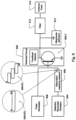
- the circuit may include a pulse generator configured to generate signal pulses. These signal pulses can be used to provide the control signals to the switched circuit shown in Fig. 4 .
- the circuit may also include a dielectric resonator oscillator configured to generate a radio frequency oscillating signal.
- the circuit may also include a switched amplifier circuit coupled to the pulse generator and the dielectric resonator oscillator.
- the switched amplifier circuit may be configured to generate a pulsed radio frequency oscillating signal in accordance with the signal pulses and radio frequency oscillating signal.
- the circuit may also include an antenna feed coupled with an output of the switched amplifier circuit to accept the pulsed radio frequency oscillating signal and emit radio frequency pulses in accordance with the pulsed radio frequency oscillating signal via an antenna.
- the dielectric resonator oscillator may include a dielectric resonator and a transistor.
- the transistor may have a drain, a gate and a source, and the dielectric resonator may be coupled to the gate and to the drain of the transistor.
- the amplifier may include a transistor having a drain, a gate and a source and the amplifier may be configured to amplify the radio frequency oscillating signal synchronously with the pulse signal to generate the pulsed radio frequency oscillating signal.
- the drain may be coupled to receive the signal pulses from the pulse generator.
- the gate may be coupled to receive the radio frequency oscillating signal from the dielectric resonator oscillator.
- the circuit may also include a filter and a set of magnitude detectors both coupled with the antenna feed.
- the magnitude detectors may be configured to detect signals received with the antenna feed based on signals generated from the switched amplifier circuit.
- Some embodiments of the present technology may involve a circuit for generating signals to produce radio frequency pulses for range gated physiology sensing.
- the circuit may include a pulse generator configured to generate signal pulses.
- the circuit may also include a dielectric resonator oscillator configured to generate a radio frequency oscillating signal.
- the circuit may also include a switched oscillator circuit coupled to the pulse generator and the dielectric oscillator.
- the switch oscillator circuit may be configured to generate a pulsed radio frequency oscillating signal in accordance with the signal pulses and radio frequency oscillating signal.
- the circuit may also include an antenna feed coupled with an output of the switched oscillator circuit to accept the pulsed radio frequency oscillating signal and to emit radio frequency pulses in accordance with the pulsed radio frequency oscillating signal via an antenna.
- the dielectric resonator oscillator may include a dielectric resonator and a transistor.
- the transistor has a drain, a gate and a source, and the dielectric resonator may be coupled to the gate and to the drain of the transistor.
- the switched oscillator circuit may include a wideband oscillator.
- the wideband oscillator may be configured to injection lock with the dielectric resonator oscillator.
- the switched oscillator circuit may include a transistor having a drain, a gate and a source and the switched oscillator circuit may include a feedback network coupled to the drain.
- An attenuator and matching network may couple the radio frequency oscillating signal output of the dielectric resonator oscillator with the gate of the transistor of the switched oscillator circuit by a microstrip feed line coupled to the gate of the transistor of the switched oscillation circuit.
- the microstrip feed line may be in a direct configuration or it may be in an indirect configuration.
- the pulse generator may be coupled with a gate of a transistor of the switched oscillator circuit.
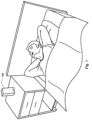
- some embodiments of the present technology may implement a sensing or detection apparatus 100 useful for detecting physiological characteristics of a user or patient in the vicinity of the apparatus.
- the sensor may be a standalone sensor or may be coupled with other apparatus, such as a respiratory treatment apparatus, so as to provide an automated treatment response based on an analysis of the physiological characteristics detected by the sensor of the apparatus.
- a respiratory treatment apparatus with a controller and a flow generator may be configured with such a sensor and may be configured to adjust a pressure treatment generated at a patient interface (e.g., mask) in response to physiological characteristics detected by the sensor.
- a typical sensor of such an apparatus may employ a transmitter to emit radio frequency waves, such as radio frequency pulses for range gated sensing.
- a receiver which may optionally be included in a combined device with the transmitter, may be configured to receive and process reflected versions of the waves.
- Signal processing may be employed, such as with a processor of the apparatus that activates the sensor, to derive physiological characteristics based on the received reflected signals.
- the transmitter transmits a radio-frequency signal towards a subject, e.g., a human.
- a subject e.g., a human.
- the source of the RF signal is a local oscillator (LO).
- the reflected signal is then received, amplified and mixed with a portion of the original signal, and the output of this mixer may then be filtered.
- the resulting signal may contain information about the movement, respiration and cardiac activity of the person, and is referred to as the raw motion sensor signal.
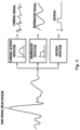
- FIG. 3 is a diagram illustrating processing of the raw sensor signal to produce indicators of the physiological characteristics.
- the raw signal will generally contain components reflecting a combination of bodily movement, respiration, and cardiac activity. Bodily movement can be identified by using zero-crossing or energy envelope detection algorithms (or more complex algorithms), and used to form a "motion on" or "motion off' indicator. For example, such movement detection algorithms may be implemented in accordance Publ. No. 2009/0203972 .
- the respiratory activity is typically in the range 0.1 to 0.8 Hz, and can be derived by filtering the original signal with a bandpass filter with a passband in that region.
- the cardiac activity is reflected in signals at higher frequencies, and this activity can be accessed by filtering with a bandpass filter with a pass band of a range from 1 to 10Hz.
- Such a respiration and movement sensor may be a range gated RF motion detector.
- the sensor may be configured to accept a DC power supply input and provide four analog motion channel outputs with both in-phase and quadrature components of the respiration and movement signals of a person within the detection range.
- range gating can help to limit movement detection to only a preferred zone or range. Thus, detections made with the sensor may be within a defined distance from the sensor.
- the RF pulses should have a fast turn-on and settling time characteristic.
- a wideband RF oscillator with a low Q factor tuned circuit may be suitable for such embodiments. Switching the wideband RF oscillator ON and OFF can allow the oscillator to generate the RF pulses.
- wideband oscillators are prone to frequency stability issues. Accordingly, embodiments of the present technology may dramatically improve RF oscillator frequency stability while maintaining the fast switching characteristics required for range gating.
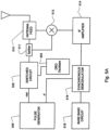
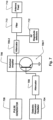
- 402 according to the present invention employs an oscillator 404, such as a dielectric resonant oscillator (DRO).
- DRO dielectric resonant oscillator
- the oscillator 404 is coupled with a switched circuit, such as a switched wideband oscillator or a switched amplifier.
- the DRO oscillator 404 may produce a stable RF oscillation signal such as when it is kept continuously ON during pulsed transmissions rather than being powered ON and OFF by switching the DRO oscillator's power source.
- the stable radio frequency oscillation signal 404-CRF (continuous radio frequency) continuously output from the DRO oscillator 404 may then be applied to an input of the switched circuit 406.
- injection locking may be employed to stabilize the switched wideband oscillator to provide both frequency stability and fast oscillator turn on with good OFF attenuation characteristics.
- the switched circuit 406 when in the form of a wideband oscillator, may be injection locked by the DRO oscillator 404.
- the wideband amplification of the DRO oscillator's RF output signal can provide both frequency stability and an even faster turn on time.
- the oscillator 606 may be injection locked by the DRO oscillator 604. Injection locking occurs when the wideband oscillator 606 is disturbed by the DRO oscillator 604 operating at a nearby frequency. Since the coupling is strong enough and the frequencies near enough, the DRO oscillator can capture the wideband oscillator, causing it to have essentially identical frequency as the DRO oscillator. Thus, in a typical embodiment, these two oscillators have a suitable "lock-in range" for injection locking.
- the bias circuit of the switched oscillator 606 is also supplied with a digital pulse from the pulse generator 608 so that oscillations can only occur during the application of the switch pulse. As illustrated in Fig. 6 , this output of the pulse generator is also input to the gate or base of the transistor 606-T of the switched oscillator 606.
- the switched oscillator then produces a frequency radar pulse at the stable reference frequency when a positive pulse is applied to the base circuit by the pulse timing circuit or pulse generator.
- the pulse generator may include a fast logic gate (e.g., a NAND gate or AND gate circuit) to generate the timing pulse.
- the output of the logic gate may be applied to a circuit network configured to maintain a wideband characteristic to ensure fast and effective switching of the switched oscillator.
- the pulsed RF frequency output from the switched oscillator 606 is then input to the peak/magnitude detectors 612 and filter(s) 613.
- this pulsed RF frequency output may be input to these components via a series resistor or via an attenuator network.
- the series resistor can be implemented to optimise the drive level to the magnitude detectors, isolate the switched oscillator from signal reflections and improve system impedance match.
- the filter 613 may be implemented with a microstrip bandpass filter and connected to the antenna feed 610.
- the microstrip bandpass filter may be implemented to ensure high rejection of out of band interfering signals and low harmonic emissions from the sensor.
- This filter may provide high rejection at radio/TV broadcast, Wi-Fi, DECT, ISM and mobile phone frequencies commonly encountered in domestic and clinical environments.
- the filter may also provide sufficiently high rejection at the second harmonic frequency (e.g., 21.05GHz in the case of a 10.525GHz oscillator) to ensure regulatory product compliance in all world markets.
- the filter may be a high performance sub-miniature energy-trapping low insertion loss coupled H resonator bandpass filter in some embodiments.
- the magnitude detectors 612 can be implemented to provide two phase separated receive I & Q channel IF signals that are proportional to the magnitude sum of the forward propagating and reverse propagating radar signals.
- the inputs to each magnitude detector may be separated along a microstrip feed line by a distance of ⁇ /8 as previously discussed.
- the separation distance may be different.
- the I & Q magnitude detector separation distance may be generalized to +/(2n-l) ⁇ /8.
- the separation distance may optionally be chosen according to any of the following distances: ⁇ /8, 3 ⁇ /8, 5 ⁇ /8, 7 ⁇ /8, ..., etc.
- FIG. 7 Alternative embodiments of the present technology in which the switched circuit is provided in an amplification configuration may be considered in view of the illustrations of Figs. 7 and 8 .
- This embodiment is similar to that of the embodiment of Fig. 6 .
- the circuit employs a switched wideband amplifier 706.
- the amplifier is implemented in a common source configuration.
- alternative configurations may be implemented in some embodiments (e.g., common drain or common gate.)
- the high stability dielectric resonator oscillator 704 and the pulse generator 708 may employ the configuration discussed with regard to the embodiment of Fig. 6 .
- the output signal from the DRO reference oscillator 704 is input to attenuator 709.
- the attenuator ensures frequency stable operation of the reference oscillator under all conditions and is configured to apply an optimum drive level to the switched amplifier 706.
- the switched power amplifier may include a transistor 706-T, such as an FET.
- the pulse switching signal from the pulse generator is applied to the drain (collector) of the transistor 706-T.
- the attenuated signal from the DRO oscillator 704 is applied to the gate (base) of the transistor 706-T.
- the source (emitter) of the transistor 706-T may be coupled to a ground, such as a ground plane of a printed circuit board (PCB) on which the circuit is formed.
- PCB printed circuit board
- the switched power amplifier thereby produces an amplified radar pulse at the stable reference frequency (e.g., 10.525GHz) when a positive pulse is applied to the drain (collector) by the timing of the pulse generator circuit, which may include circuit components, such as series resistor, series inductor and capacitors, configured to ensure fast switching and minimal overshoot of the modulation pulse applied to the modulated amplifier 706.
- the pulse generator circuit may include circuit components, such as series resistor, series inductor and capacitors, configured to ensure fast switching and minimal overshoot of the modulation pulse applied to the modulated amplifier 706.
- the pulsed radio frequency output from the modulated power amplifier 706 is fed via an optional second attenuator 709-2, through the magnitude detectors 712, through filter 713 (e.g., bandpass filter as previously described in reference to Fig. 6 ) to the sensor antenna (such as a horn probe antenna) or antenna feed 710.
- the second attenuator 709-2 may be configured to optimise the drive level to the magnitude detectors and improve system impedance match. This second attenuator can be omitted in some embodiments.
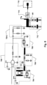
- Fig. 8 is a circuit diagram showing an example circuit suitable for implementation as the amplifier embodiment of Fig. 7 in some sensors of the present technology. Example components thereof have been outlined and numbered accordingly.
- Some potential advantages of the circuit configuration of Fig. 8 may include the elimination of the lock-in range requirements. As seen in the figure, the circuit complexity associated with implementation of a wideband oscillator is reduced. As a further advantage, the turn on time of the wideband RF amplifier can be faster than the wideband RF oscillator.
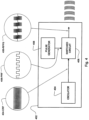
- the timing of the pulse generation circuit can be dithered with respect to the underlying pulse repetition frequency by inclusion of a dithering circuit (not shown) such as one coupled with or included with a pulse generator 408.
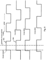
- Fig. 9 shows a signal representation of "dithering" of the pulse generation (in which the onset time of the pulse varies with respect to the overall pulse generation timing).
- the overall pulse repetition frequency can be varied, so that the pulse onset time is linearly delayed or advanced with respect to the nominal overall pulse center (i.e., the second pulse train 902 is at a slower pulse repetition frequency than the first pulse train 901). This has the net effect of changing the position of the pulse onset time, compared to its nominal onset time if the PRF remained fixed.
- An example synchronous ramp dithering circuit may be implemented with a voltage controlled delay element based on an underlying RC (resistor-capacitor) time constant.
- the ramp control voltage results in a varying varactor capacitance which in turn results in a varying resonator frequency.
- the frequency of the pulse generation circuit oscillator and associated PRF is varied on the order of about 1% in a synchronous and linear manner every lms approximately.
- Dithering is utilised because it removes synchronous RF demodulation noise artefacts.
- Ramp dithering is utilised because it is easy to realise however it can produce tone artefacts. Synchronous ramp dithering prevents these unwanted tones from being generated.
- FETs Field Effect Transistors
- BJT Bipolar Junction Transistor
- N has been illustrated to refer to number of times certain operations may be performed. In some cases, for example, N may be 128. However, a large range may be suitable (e.g., N may be in a range from 16 to 32768) so as to provide plausible designs for different cases.
- t0 and t1 have been referred to an offset time. Such an offset time may, for example, be on the order of nanoseconds, such as 5 ns.
- ⁇ t has been used to refer to a turn on time.
- Such a turn on time may also be on the order of nanoseconds, such as for example, 50 ns.
- a "BW" bandwidth of an oscillator described herein may be on the order of megahertz, such as, for example about 20 MHz.
Landscapes
- Health & Medical Sciences (AREA)
- Life Sciences & Earth Sciences (AREA)
- Engineering & Computer Science (AREA)
- Physics & Mathematics (AREA)
- Medical Informatics (AREA)
- Public Health (AREA)
- Veterinary Medicine (AREA)
- Animal Behavior & Ethology (AREA)
- Surgery (AREA)
- General Health & Medical Sciences (AREA)
- Molecular Biology (AREA)
- Biophysics (AREA)
- Pathology (AREA)
- Biomedical Technology (AREA)
- Heart & Thoracic Surgery (AREA)
- Physiology (AREA)
- Radar, Positioning & Navigation (AREA)
- Remote Sensing (AREA)
- Dentistry (AREA)
- Oral & Maxillofacial Surgery (AREA)
- Signal Processing (AREA)
- Cardiology (AREA)
- Pulmonology (AREA)
- General Physics & Mathematics (AREA)
- Computer Networks & Wireless Communication (AREA)
- Nuclear Medicine, Radiotherapy & Molecular Imaging (AREA)
- Radiology & Medical Imaging (AREA)
- Psychiatry (AREA)
- Computer Vision & Pattern Recognition (AREA)
- Artificial Intelligence (AREA)
- Power Engineering (AREA)
- Radar Systems Or Details Thereof (AREA)
- Measurement Of The Respiration, Hearing Ability, Form, And Blood Characteristics Of Living Organisms (AREA)
- Anesthesiology (AREA)
- Measuring Pulse, Heart Rate, Blood Pressure Or Blood Flow (AREA)
Claims (14)
- Funkfrequenz-Bewegungssensor, Folgendes aufweisend:einen Funkfrequenzsender, der zum Aussenden von Funkfrequenzpulsen konfiguriert ist; undeinen Schaltempfänger, der zum Empfangen von reflektierten der ausgesendeten Funkfrequenzpulse konfiguriert ist,wobei der Funkfrequenzsender aufweist:
einen Pulsgenerator (405, 508), der zum Generieren von Signalpulsen konfiguriert ist:einen Oszillator (406, 506) mit dielektrischem Resonator, der zum Generieren eines stabilen oszillierenden Funkfrequenzsignals konfiguriert ist;eine Schaltanordnung, die mit dem Pulsgenerator und dem Oszillator mit dielektrischem Resonator gekoppelt ist, wobei die Schaltanordnung zum Generieren eines gepulsten oszillierenden Funkfrequenzsignals konfiguriert ist, das von den Signalpulsen des Pulsgenerators moduliert wird und dessen dominante Frequenz von dem Oszillator mit dielektrischem Resonator abgeleitet ist,dadurch gekennzeichnet, dass die Schaltempfänger aufweisteinen Signalstärkedetektor-Homodynempfänger (512), der in Übereinstimmung mit einem Taktsignal von dem Pulsgenerator geschaltet wird, wobei der Signalstärkedetektor-Homodynempfänger für eine Zeitdauer T zu einer ersten Versatzzeit (t0) von einer nominalen Startzeit eines Signalpulses eingeschaltet wird, was zu einem ersten Empfangspegel (t0-Empfangspegel) führt, und für eine Zeitdauer T zu einer zweiten Versatzzeit (t1) von der nominalen Startzeit des Signalpulses eingeschaltet wird, was zu einem zweiten Empfangspegel (t1-Empfangspegel) führt,einen Zwischenfrequenzverstärker (514), der zum Verstärken der Ausgabe des Signalstärkedetektor-Homodynempfängers konfiguriert ist,einen Synchrondemodulator (516), der zum Empfangen der Ausgabe des Zwischenfrequenzverstärkers und zum Erfassen der Differenz zwischen dem ersten Empfangspegel und dem zweiten Empfangspegel konfiguriert ist,eine Basisbandschaltung (518), die zum Verstärken und anschließenden Filtern der Ausgabe des synchronen Demodulators konfiguriert ist, um ein Maß für die Bewegung des menschlichen Körpers bereitzustellen. - Funkfrequenz-Bewegungssensor nach Anspruch 1, wobei der Oszillator mit dielektrischem Resonator einen dielektrischen Resonator und einen Transistor aufweist.
- Funkfrequenz-Bewegungssensor nach einem der Ansprüche 1 bis 2, wobei die Schaltanordnung einen schaltbaren Funkfrequenzverstärker aufweist.
- Funkfrequenz-Bewegungssensor nach einem der Ansprüche 1 bis 2, wobei die Schaltanordnung einen Transistor aufweist, der einen schaltbaren Breitbandverstärker bildet, und wobei getrennte Signale optional von dem Oszillator mit dielektrischem Resonator und dem Pulsgenerator beide in den Gate-Anschluss bzw. den Drain-Anschluss des Transistors des schaltbaren Breitbandverstärkers eingegeben werden.
- Funkfrequenz-Bewegungssensor nach einem der Ansprüche 1 bis 2, wobei die Schaltanordnung einen Breitbandoszillator aufweist, wobei der Breitbandoszillator zum Injection Locking mit dem Oszillator mit dielektrischem Resonator konfiguriert ist.
- Funkfrequenz-Bewegungssensor nach einem der Ansprüche 1 bis 2, wobei die Schaltanordnung einen Transistor aufweist, der einen schaltbaren Breitbandoszillator mit einer Rücckopplungsnetzschaltung bildet, die mit dem Drain-Anschluss des Transistors gekoppelt ist, und wobei getrennte Signale optional von dem Oszillator mit dielektrischem Resonator und dem Pulsgenerator beide in den Gate-Anschluss des Transistors des schaltbaren Breitbandoszillators eingegeben werden.
- Funkfrequenz-Bewegungssensor nach einem der Ansprüche 1 bis 6, wobei der Pulsgenerator eine Logikgatterschaltung aufweist.
- Funkfrequenz-Bewegungssensor nach Anspruch 7, wobei ein Ausgang des Logikgatters der Logikgatterschaltung mit einem Gate-Anschluss eines Transistors der Schaltanordnung gekoppelt ist
und wobei die Logikgatterschaltung optional ein NAND-Gatter aufweist. - Funkfrequenz-Bewegungssensor nach einem der Ansprüche 1 bis 8, ferner aufweisend eine Antennenzuleitung, die zum Entgegennehmen des generierten gepulsten oszillierenden Funkfrequenzsignals und zum Aussenden von dem gepulsten oszillierenden Funkfrequenzsignal entsprechenden ausgesendeten Funkfrequenzpulsen über eine Antenne mit einem Ausgang der Schaltanordnung gekoppelt ist.
- Funkfrequenz-Bewegungssensor nach einem der Ansprüche 1 bis 9, wobei eine Einsetzzeit der Signalpulse in Bezug auf den Signalpuls-Generierungszeitpunkt insgesamt variiert wird.
- Funkfrequenz-Bewegungssensor nach einem der Ansprüche 1 bis 10, ferner aufweisend einen Prozessor, wobei der Prozessor zum Verarbeiten der empfangenen reflektierten der ausgesendeten Funkfrequenzpulse konfiguriert ist, um einen Indikator für eine Körperbewegung und/oder Atmung und/oder Schlaf und/oder Herzfrequenz abzuleiten,
und optional ferner aufweisend eine Atembehandlungsvorrichtung, wobei die Atembehandlungsvorrichtung einen Strömungsgenerator mit einem Prozessor aufweist, wobei der Prozessor der Atembehandlungsvorrichtung zum Verarbeiten des Indikators konfiguriert ist. - Funkfrequenz-Bewegungssensor nach einem der Ansprüche 1 bis 11, wobei der Funkfrequenz-Bewegungssensor ferner eine Dither-Schaltung aufweist, wobei die Dither-Schaltung zum Modulieren von Signalpulsen, die von dem Pulsgenerator generiert wurden, mit dem Pulsgenerator gekoppelt ist,
und wobei die Dither-Schaltung optional eine Synchronrampen-Dither-Schaltung ist. - Funkfrequenz-Bewegungssensor nach einem der Ansprüche 1 bis 12, wobei der Schaltempfänger zum Erzeugen eines Maßes für die Größe und Phase eines empfangenen Signals in Bezug auf ein gesendetes Signal konfiguriert ist, wobei das empfangene Signal den empfangenen reflektierten der gesendeten Funkfrequenzpulse und das gesendete Signal den gesendeten Funkfrequenzpulsen entspricht.
- Funkfrequenz-Bewegungssensor nach einem der Ansprüche 1 bis 13, wobei der Schaltempfänger eine Entfernungszone für die Erfassung bereitstellt,
wobei der Funkfrequenz-Bewegungssensor einen bereichsgesteuerten Bewegungssensor für die Herz- und/oder Atemphysiologie aufweist.
Applications Claiming Priority (3)
| Application Number | Priority Date | Filing Date | Title |
|---|---|---|---|
| US201261673774P | 2012-07-20 | 2012-07-20 | |
| EP13819553.2A EP2874535B1 (de) | 2012-07-20 | 2013-07-19 | Bereichsgesteuerter physiologischer radiofrequenzsensor |
| PCT/US2013/051250 WO2014015238A1 (en) | 2012-07-20 | 2013-07-19 | Range gated radio frequency physiology sensor |
Related Parent Applications (1)
| Application Number | Title | Priority Date | Filing Date |
|---|---|---|---|
| EP13819553.2A Division EP2874535B1 (de) | 2012-07-20 | 2013-07-19 | Bereichsgesteuerter physiologischer radiofrequenzsensor |
Publications (2)
| Publication Number | Publication Date |
|---|---|
| EP3733059A1 EP3733059A1 (de) | 2020-11-04 |
| EP3733059B1 true EP3733059B1 (de) | 2025-06-25 |
Family
ID=49947123
Family Applications (2)
| Application Number | Title | Priority Date | Filing Date |
|---|---|---|---|
| EP13819553.2A Active EP2874535B1 (de) | 2012-07-20 | 2013-07-19 | Bereichsgesteuerter physiologischer radiofrequenzsensor |
| EP20164431.7A Active EP3733059B1 (de) | 2012-07-20 | 2013-07-19 | Bereichsgesteuerter physiologischer funkfrequenzsensor |
Family Applications Before (1)
| Application Number | Title | Priority Date | Filing Date |
|---|---|---|---|
| EP13819553.2A Active EP2874535B1 (de) | 2012-07-20 | 2013-07-19 | Bereichsgesteuerter physiologischer radiofrequenzsensor |
Country Status (7)
| Country | Link |
|---|---|
| US (3) | US9445729B2 (de) |
| EP (2) | EP2874535B1 (de) |
| JP (1) | JP6313297B2 (de) |
| CN (1) | CN104703533B (de) |
| AU (1) | AU2013292346B2 (de) |
| NZ (1) | NZ702970A (de) |
| WO (1) | WO2014015238A1 (de) |
Families Citing this family (55)
| Publication number | Priority date | Publication date | Assignee | Title |
|---|---|---|---|---|
| US9724010B2 (en) | 2010-07-08 | 2017-08-08 | Emtensor Gmbh | Systems and methods of 4D electromagnetic tomographic (EMT) differential (dynamic) fused imaging |
| US9445729B2 (en) | 2012-07-20 | 2016-09-20 | Resmed Sensor Technologies Limited | Range gated radio frequency physiology sensor |
| US9414749B2 (en) | 2012-11-21 | 2016-08-16 | Emtensor Gmbh | Electromagnetic tomography solutions for scanning head |
| US9072449B2 (en) * | 2013-03-15 | 2015-07-07 | Emtensor Gmbh | Wearable/man-portable electromagnetic tomographic imaging |
| US20140275944A1 (en) | 2013-03-15 | 2014-09-18 | Emtensor Gmbh | Handheld electromagnetic field-based bio-sensing and bio-imaging system |
| USD765256S1 (en) | 2014-05-09 | 2016-08-30 | Resmed Sensor Technologies Limited | Apparatus for sleep information detection |
| JP6698521B2 (ja) | 2013-07-08 | 2020-05-27 | レスメッド センサー テクノロジーズ リミテッド | 睡眠管理の方法及びシステム |
| US11648373B2 (en) | 2013-07-08 | 2023-05-16 | Resmed Sensor Technologies Limited | Methods and systems for sleep management |
| US9344127B2 (en) * | 2013-11-22 | 2016-05-17 | The Trustees Of Columbia University In The City Of New York | Graphene resonator based mixer-first receiver on CMOS for digitally controlled and widely tunable RF interface |
| US11051702B2 (en) * | 2014-10-08 | 2021-07-06 | University Of Florida Research Foundation, Inc. | Method and apparatus for non-contact fast vital sign acquisition based on radar signal |
| US9924880B2 (en) * | 2015-02-11 | 2018-03-27 | Samsung Electronics Co., Ltd. | RF doppler bio-signal sensor for continuous heart rate variability and blood pressure monitoring |
| US10670700B2 (en) * | 2015-04-20 | 2020-06-02 | Resmed Sensor Technologies Limited | Multi sensor radio frequency detection |
| CN113940655B (zh) | 2015-04-20 | 2024-08-20 | 瑞思迈传感器技术有限公司 | 用传感器进行手势识别 |
| EP3286577B1 (de) | 2015-04-20 | 2021-03-17 | ResMed Sensor Technologies Limited | Nachweis und identifizierung eines menschlichen signals aus charakteristischen signalen |
| JP6586557B2 (ja) * | 2015-04-20 | 2019-10-09 | 株式会社スリープシステム研究所 | 睡眠段階判定装置及び睡眠段階判定方法 |
| WO2016205891A1 (en) | 2015-06-26 | 2016-12-29 | Resmed Limited | Diagnosis and monitoring of cardio-respiratory disorders |
| JP2018531370A (ja) * | 2015-08-14 | 2018-10-25 | レスメッド センサー テクノロジーズ リミテッド | デジタルレンジゲート無線周波数センサー |
| WO2017032873A2 (en) | 2015-08-26 | 2017-03-02 | Resmed Sensor Technologies Limited | Systems and methods for monitoring and management of chronic desease |
| DK3361955T3 (da) | 2015-10-16 | 2020-10-26 | Emtensor Gmbh | Elektromagnetisk interferensmønstergenkendelsestomografi |
| US12207949B2 (en) | 2015-12-08 | 2025-01-28 | ResMed Pty Ltd | Non-contact diagnosis and monitoring of sleep disorders |
| JP6642055B2 (ja) * | 2016-02-02 | 2020-02-05 | 富士通株式会社 | センサ情報処理装置、センサユニット、及び、センサ情報処理プログラム |
| WO2017198787A1 (en) | 2016-05-19 | 2017-11-23 | Pmd Device Solutions Limited | An apparatus and method for detection of dysfunctional breathing |
| CN107440695B (zh) * | 2016-05-31 | 2020-10-16 | 佳纶生技股份有限公司 | 生理信号感测装置 |
| US10411716B2 (en) * | 2016-06-06 | 2019-09-10 | Richwave Technology Corp. | Subsampling motion detector for detecting motion of object under measurement |
| EP3474036A4 (de) * | 2016-06-21 | 2019-06-26 | Cis4U | Sensor zur erkennung eines menschlichen körpers mittels doppler-radar |
| US10338206B2 (en) * | 2016-06-21 | 2019-07-02 | Robert Bosch Gmbh | Ultra-wideband radar with normalized sensitivity |
| CN106264509A (zh) * | 2016-08-16 | 2017-01-04 | 深圳欧德蒙科技有限公司 | 一种心率测量装置和方法 |
| WO2018033574A1 (en) | 2016-08-16 | 2018-02-22 | Resmed Sensor Technologies Limited | Digital radio frequency motion detection sensor |
| US11103661B2 (en) | 2016-09-14 | 2021-08-31 | ResMed Pty Ltd | Apparatus and method for adaptive ramped control of positive airway pressure (PAP) |
| WO2018098387A1 (en) | 2016-11-23 | 2018-05-31 | Emtensor Gmbh | Use of electromagnetic field for tomographic imaging of head |
| KR102338204B1 (ko) * | 2017-08-02 | 2021-12-10 | 한국전자통신연구원 | 생체 신호 감지 장치 및 이를 포함하는 생체 신호 감지 시스템 |
| JP6932090B2 (ja) * | 2017-09-27 | 2021-09-08 | シャープ株式会社 | 監視装置 |
| TWI642406B (zh) * | 2017-12-12 | 2018-12-01 | Sil Radar Technology Inc. | 非接觸式自我注入鎖定感測器 |
| JP7464522B2 (ja) | 2017-12-22 | 2024-04-09 | レスメッド センサー テクノロジーズ リミテッド | 動き感知のための装置、システムおよび方法 |
| EP3727145B1 (de) | 2017-12-22 | 2024-01-24 | ResMed Sensor Technologies Limited | Vorrichtung, system und verfahren zur physiologischen abtastung in fahrzeugen |
| KR102658390B1 (ko) | 2017-12-22 | 2024-04-17 | 레스메드 센서 테크놀로지스 리미티드 | 건강 및 의료 감지를 위한 장치, 시스템, 및 방법 |
| CN108567416A (zh) * | 2018-02-01 | 2018-09-25 | 张玲玲 | 一种心血管临床脉搏检测装置 |
| TWI675218B (zh) * | 2018-06-07 | 2019-10-21 | 國立中山大學 | 可抵抗雜波之生理徵象感測器 |
| WO2020072297A1 (en) | 2018-10-03 | 2020-04-09 | Arizona Board Of Regents On Behalf Of Arizona State University | Direct rf signal processing for heart-rate monitoring using uwb impulse radar |
| EP3883468A2 (de) | 2018-11-19 | 2021-09-29 | ResMed Sensor Technologies Limited | Verfahren und vorrichtung zur erkennung von atmungsstörungen |
| US12274527B2 (en) * | 2019-03-20 | 2025-04-15 | Arizona Board Of Regents On Behalf Of Arizona State University | Radar cardiography: a precise cardiac data reconstruction method |
| US12127825B2 (en) * | 2019-05-08 | 2024-10-29 | Google Llc | Sleep tracking and vital sign monitoring using low power radio waves |
| WO2021086809A1 (en) * | 2019-10-28 | 2021-05-06 | Arizona Board Of Regents On Behalf Of Arizona State University | Methods and systems for remote sleep monitoring |
| US11988772B2 (en) | 2019-11-01 | 2024-05-21 | Arizona Board Of Regents On Behalf Of Arizona State University | Remote recovery of acoustic signals from passive sources |
| WO2021118602A1 (en) | 2019-12-13 | 2021-06-17 | Google Llc | Heart beat measurements using a mobile device |
| US20230190140A1 (en) | 2020-05-19 | 2023-06-22 | Resmed Sensor Technologies Limited | Methods and apparatus for detection and monitoring of health parameters |
| WO2021257898A1 (en) | 2020-06-18 | 2021-12-23 | Circadia Technologies Ltd. | Systems, apparatus and methods for acquisition, storage, and analysis of health and environmental data |
| US12070324B2 (en) | 2020-08-11 | 2024-08-27 | Google Llc | Contactless sleep detection and disturbance attribution for multiple users |
| KR102289031B1 (ko) * | 2020-08-28 | 2021-08-11 | (주)그린아이티코리아 | 레이더를 이용하여 바이탈 신호를 감지하는 방법 및 장치 |
| TWI803848B (zh) * | 2021-03-29 | 2023-06-01 | 國立勤益科技大學 | 一種帕金森氏症上肢震顫分析裝置與方法 |
| EP4088651A1 (de) | 2021-05-12 | 2022-11-16 | Ectosense NV | Verfahren zur erkennung von schlafstörenden ereignissen |
| US20240302293A1 (en) * | 2023-03-09 | 2024-09-12 | Omnizare Imaging Inc. | Detecting and imaging using dielectric tomography |
| WO2025128872A1 (en) * | 2023-12-13 | 2025-06-19 | Arizona Board Of Regents On Behalf Of Arizona State University | System and method for radar-based heart sound detection |
| US12379462B1 (en) * | 2024-04-26 | 2025-08-05 | Airtouch Intelligent Technology (Shanghai) Co., Ltd. | Height measurement device and height measurement method based on millimeter-wave radar |
| WO2025262245A1 (en) | 2024-06-21 | 2025-12-26 | Ectosense NV | Methods and apparatus for sleep monitoring |
Citations (2)
| Publication number | Priority date | Publication date | Assignee | Title |
|---|---|---|---|---|
| US5573012A (en) * | 1994-08-09 | 1996-11-12 | The Regents Of The University Of California | Body monitoring and imaging apparatus and method |
| US5682164A (en) * | 1994-09-06 | 1997-10-28 | The Regents Of The University Of California | Pulse homodyne field disturbance sensor |
Family Cites Families (44)
| Publication number | Priority date | Publication date | Assignee | Title |
|---|---|---|---|---|
| US4197537A (en) | 1976-08-19 | 1980-04-08 | Honeywell Inc. | Intruder detection system |
| US4164945A (en) * | 1977-06-13 | 1979-08-21 | Medtronic, Inc. | Digital cardiac pacemaker medical device |
| US4238796A (en) | 1979-06-28 | 1980-12-09 | Rca Corporation | Radio frequency pulse generator |
| US5309453A (en) | 1981-07-27 | 1994-05-03 | Jersey Nuclear-Avco Isotopes, Inc. | Single pulse injection locking |
| US6087971A (en) | 1982-09-13 | 2000-07-11 | The Boeing Company | Method of fabricating an improved ceramic radome |
| US4631497A (en) | 1984-06-05 | 1986-12-23 | Plessey South Africa Limited | Injection locked RF oscillator with control hoop |
| NL8915009A (nl) | 1988-11-07 | 1991-07-01 | Marconi Co Ltd | Radarstelsel. |
| JPH02146849A (ja) * | 1988-11-28 | 1990-06-06 | Nec Corp | リンガー受信回路 |
| US5142251A (en) | 1991-10-03 | 1992-08-25 | National Semiconductor Corporation | Wide band selectable gain and operating frequency CMOS oscillator circuit |
| US5361070B1 (en) | 1993-04-12 | 2000-05-16 | Univ California | Ultra-wideband radar motion sensor |
| JPH0794946A (ja) * | 1993-09-20 | 1995-04-07 | Fujitsu General Ltd | 周波数可変型マイクロ波発振器 |
| US5623233A (en) | 1993-11-10 | 1997-04-22 | The United States Of America As Represented By The Secretary Of The Army | Pulsed optically injection locked MESFET oscillator |
| US5757241A (en) | 1996-12-31 | 1998-05-26 | Millitech Corporation | Pulse amplification apparatus and method |
| JP3340654B2 (ja) | 1997-10-20 | 2002-11-05 | 株式会社アドバンテスト | スペクトラムアナライザ |
| US5986600A (en) | 1998-01-22 | 1999-11-16 | Mcewan; Thomas E. | Pulsed RF oscillator and radar motion sensor |
| EP0940690A3 (de) | 1998-03-05 | 2000-11-29 | The Whitaker Corporation | Mikrowellensensor zur Zielbewegungsdetektion |
| US5966090A (en) | 1998-03-16 | 1999-10-12 | Mcewan; Thomas E. | Differential pulse radar motion sensor |
| US8636648B2 (en) * | 1999-03-01 | 2014-01-28 | West View Research, Llc | Endoscopic smart probe |
| US10973397B2 (en) * | 1999-03-01 | 2021-04-13 | West View Research, Llc | Computerized information collection and processing apparatus |
| US6535766B1 (en) * | 2000-08-26 | 2003-03-18 | Medtronic, Inc. | Implanted medical device telemetry using integrated microelectromechanical filtering |
| US6426716B1 (en) | 2001-02-27 | 2002-07-30 | Mcewan Technologies, Llc | Modulated pulse doppler sensor |
| FR2825854B1 (fr) * | 2001-06-07 | 2003-09-05 | Thomson Licensing Sa | Oscillateur multi-frequences a resonateur dielectrique |
| US7811234B2 (en) | 2002-08-01 | 2010-10-12 | California Institute Of Technology | Remote-sensing method and device |
| CA2395891A1 (en) * | 2002-08-12 | 2004-02-12 | Ralph Dickson Mason | Injection locking using direct digital tuning |
| US20040249257A1 (en) | 2003-06-04 | 2004-12-09 | Tupin Joe Paul | Article of manufacture for extracting physiological data using ultra-wideband radar and improved signal processing techniques |
| DE102005008733A1 (de) * | 2004-02-26 | 2005-10-13 | Kyocera Corp. | Sende-/Empfangsantenne, Isolator, Hochfrequenzoszillator und dieselben verwendender Hochfrequenz-Sender/Empfänger |
| US20050203348A1 (en) * | 2004-03-01 | 2005-09-15 | Musa Shihadeh | Remote cardiac arrest monitor |
| DE602005024952D1 (de) * | 2004-05-26 | 2011-01-05 | Medical Device Innovations Ltd | Gewebenachweis- und ablationsgerät |
| GB0421178D0 (en) | 2004-09-23 | 2004-10-27 | Univ St Andrews | A fast pulse generator |
| FR2877519B1 (fr) * | 2004-10-29 | 2007-01-19 | Groupe Ecoles Telecomm | Generateur d'impulsions et emetteur radiofrequence ultra large bande |
| JP4495169B2 (ja) * | 2004-11-30 | 2010-06-30 | 三菱電機株式会社 | パルス変調回路 |
| IL171817A (en) | 2005-11-07 | 2013-03-24 | Beam Networks Ltd | Apparatus and methods for radar imaging based on injected push-push oscillators |
| AU2007256872B2 (en) | 2006-06-01 | 2013-03-14 | Resmed Sensor Technologies Limited | Apparatus, system, and method for monitoring physiological signs |
| US7608808B2 (en) | 2006-11-07 | 2009-10-27 | Canon Kabushiki Kaisha | Injection-locked pulsed laser with high wavelength stability |
| US7952515B2 (en) | 2009-02-26 | 2011-05-31 | Mcewan Technologies, Llc | Range gated holographic radar |
| US7994968B2 (en) | 2009-02-26 | 2011-08-09 | Mcewan Technologies, Llc | RF magnitude sampler for holographic radar |
| GB0911568D0 (en) * | 2009-07-03 | 2009-08-12 | Eosemi Ltd | Improvements in the fine tuning of electronic oscillators |
| WO2011006199A1 (en) * | 2009-07-16 | 2011-01-20 | Resmed Ltd | Detection of sleep condition |
| US8138844B1 (en) | 2010-09-10 | 2012-03-20 | Fujitsu Semiconductor Limited | System and method for crystal oscillator frequency tuning |
| US8432198B2 (en) | 2010-09-10 | 2013-04-30 | Mediatek Inc. | Injection-locked phase-locked loop with a self-aligned injection window |
| WO2012048020A1 (en) * | 2010-10-05 | 2012-04-12 | Joint Vue, LLC | Uwb microwave imaging system with a novel calibration approach for breast cancer detection |
| GB201021032D0 (en) * | 2010-12-10 | 2011-01-26 | Creo Medical Ltd | Electrosurgical apparatus |
| US9691873B2 (en) * | 2011-12-01 | 2017-06-27 | The Board Of Trustees Of The University Of Illinois | Transient devices designed to undergo programmable transformations |
| US9445729B2 (en) * | 2012-07-20 | 2016-09-20 | Resmed Sensor Technologies Limited | Range gated radio frequency physiology sensor |
-
2013
- 2013-07-18 US US13/945,371 patent/US9445729B2/en active Active
- 2013-07-19 CN CN201380038757.3A patent/CN104703533B/zh active Active
- 2013-07-19 JP JP2015523278A patent/JP6313297B2/ja not_active Expired - Fee Related
- 2013-07-19 EP EP13819553.2A patent/EP2874535B1/de active Active
- 2013-07-19 US US14/415,677 patent/US10143386B2/en active Active
- 2013-07-19 AU AU2013292346A patent/AU2013292346B2/en not_active Ceased
- 2013-07-19 EP EP20164431.7A patent/EP3733059B1/de active Active
- 2013-07-19 NZ NZ702970A patent/NZ702970A/en not_active IP Right Cessation
- 2013-07-19 WO PCT/US2013/051250 patent/WO2014015238A1/en not_active Ceased
-
2018
- 2018-10-31 US US16/175,975 patent/US10863906B2/en active Active
Patent Citations (2)
| Publication number | Priority date | Publication date | Assignee | Title |
|---|---|---|---|---|
| US5573012A (en) * | 1994-08-09 | 1996-11-12 | The Regents Of The University Of California | Body monitoring and imaging apparatus and method |
| US5682164A (en) * | 1994-09-06 | 1997-10-28 | The Regents Of The University Of California | Pulse homodyne field disturbance sensor |
Also Published As
| Publication number | Publication date |
|---|---|
| US20150216424A1 (en) | 2015-08-06 |
| US20140024917A1 (en) | 2014-01-23 |
| CN104703533B (zh) | 2018-04-03 |
| AU2013292346B2 (en) | 2016-07-28 |
| US20190059746A1 (en) | 2019-02-28 |
| US9445729B2 (en) | 2016-09-20 |
| US10863906B2 (en) | 2020-12-15 |
| EP2874535A1 (de) | 2015-05-27 |
| EP2874535B1 (de) | 2020-03-25 |
| NZ702970A (en) | 2017-12-22 |
| WO2014015238A1 (en) | 2014-01-23 |
| AU2013292346A1 (en) | 2015-01-22 |
| EP3733059A1 (de) | 2020-11-04 |
| EP2874535A4 (de) | 2016-03-30 |
| CN104703533A (zh) | 2015-06-10 |
| JP2015529486A (ja) | 2015-10-08 |
| US10143386B2 (en) | 2018-12-04 |
| JP6313297B2 (ja) | 2018-04-18 |
Similar Documents
| Publication | Publication Date | Title |
|---|---|---|
| US10863906B2 (en) | Range gated radio frequency physiology sensor | |
| US20220000384A1 (en) | Digital range gated radio frequency sensor | |
| JP6208710B2 (ja) | 距離ゲートを用いたホログラフィックレーダおよびホログラフィックレーダセンサ | |
| JP3824655B2 (ja) | パルス同期によるフィールド外乱センサ | |
| JP3631254B2 (ja) | レンジ感度補償を行うレンジ・ゲート制御形のフィールド外乱センサ | |
| US5986600A (en) | Pulsed RF oscillator and radar motion sensor | |
| EP2159597A2 (de) | Gepulstes Radar mit verbesserter Nahbereichsauflösung | |
| JP2018531370A6 (ja) | デジタルレンジゲート無線周波数センサー | |
| CN113608174B (zh) | 多传感器射频检测 | |
| WO2000045460A2 (en) | Short pulse microwave transceiver | |
| TWI723824B (zh) | 無線鎖頻迴路之生理感測雷達 | |
| LU101016B1 (en) | A double -frequency circuit structure for implementing vital sign detection and short-distance positioning | |
| RU2392852C2 (ru) | Импульсный сверхширокополосный датчик дистанционного мониторинга дыхания и сердцебиения | |
| Peng et al. | Intermodulation FMCW (IM-FMCW) radar for nonlinear wearable targets detection | |
| CN210775831U (zh) | 雷达 | |
| Huang et al. | Non-contact and Real-time Pulse-based radar with Sensitivity Improvement for Vital-sign Monitoring | |
| Chen et al. | Non-contact Pulse-based Radar with an Excited RF Pulse Generator for Vital-sign Application | |
| JP2023547513A (ja) | 空間内の物体の電波探知のための装置、及びgprシステム | |
| Wang et al. | A 2.4-GHz noncontact vital-sign sensor based on two circulators and frequency-modulated/injection-locked VCO | |
| JPS6279042A (ja) | 超音波受信装置 |
Legal Events
| Date | Code | Title | Description |
|---|---|---|---|
| PUAI | Public reference made under article 153(3) epc to a published international application that has entered the european phase |
Free format text: ORIGINAL CODE: 0009012 |
|
| STAA | Information on the status of an ep patent application or granted ep patent |
Free format text: STATUS: THE APPLICATION HAS BEEN PUBLISHED |
|
| AC | Divisional application: reference to earlier application |
Ref document number: 2874535 Country of ref document: EP Kind code of ref document: P |
|
| AK | Designated contracting states |
Kind code of ref document: A1 Designated state(s): AL AT BE BG CH CY CZ DE DK EE ES FI FR GB GR HR HU IE IS IT LI LT LU LV MC MK MT NL NO PL PT RO RS SE SI SK SM TR |
|
| STAA | Information on the status of an ep patent application or granted ep patent |
Free format text: STATUS: REQUEST FOR EXAMINATION WAS MADE |
|
| 17P | Request for examination filed |
Effective date: 20210504 |
|
| RBV | Designated contracting states (corrected) |
Designated state(s): AL AT BE BG CH CY CZ DE DK EE ES FI FR GB GR HR HU IE IS IT LI LT LU LV MC MK MT NL NO PL PT RO RS SE SI SK SM TR |
|
| STAA | Information on the status of an ep patent application or granted ep patent |
Free format text: STATUS: EXAMINATION IS IN PROGRESS |
|
| 17Q | First examination report despatched |
Effective date: 20230118 |
|
| GRAP | Despatch of communication of intention to grant a patent |
Free format text: ORIGINAL CODE: EPIDOSNIGR1 |
|
| STAA | Information on the status of an ep patent application or granted ep patent |
Free format text: STATUS: GRANT OF PATENT IS INTENDED |
|
| RIC1 | Information provided on ipc code assigned before grant |
Ipc: A61B 5/08 20060101ALN20250109BHEP Ipc: A61B 5/024 20060101ALN20250109BHEP Ipc: A61B 5/0205 20060101ALI20250109BHEP Ipc: A61B 5/05 20060101ALI20250109BHEP Ipc: H03B 19/00 20060101ALI20250109BHEP Ipc: A61B 5/11 20060101ALI20250109BHEP Ipc: A61B 5/02 20060101AFI20250109BHEP |
|
| INTG | Intention to grant announced |
Effective date: 20250116 |
|
| GRAS | Grant fee paid |
Free format text: ORIGINAL CODE: EPIDOSNIGR3 |
|
| GRAA | (expected) grant |
Free format text: ORIGINAL CODE: 0009210 |
|
| STAA | Information on the status of an ep patent application or granted ep patent |
Free format text: STATUS: THE PATENT HAS BEEN GRANTED |
|
| AC | Divisional application: reference to earlier application |
Ref document number: 2874535 Country of ref document: EP Kind code of ref document: P |
|
| AK | Designated contracting states |
Kind code of ref document: B1 Designated state(s): AL AT BE BG CH CY CZ DE DK EE ES FI FR GB GR HR HU IE IS IT LI LT LU LV MC MK MT NL NO PL PT RO RS SE SI SK SM TR |
|
| RAP3 | Party data changed (applicant data changed or rights of an application transferred) |
Owner name: RESMED SENSOR TECHNOLOGIES LIMITED |
|
| REG | Reference to a national code |
Ref country code: GB Ref legal event code: FG4D |
|
| RIN1 | Information on inventor provided before grant (corrected) |
Inventor name: HENEGHAN, CONOR Inventor name: CONWAY, KIERAN Inventor name: WOOD, SPENCER TERRY Inventor name: WREN, MICHAEL Inventor name: MCMAHON, STEPHEN |
|
| REG | Reference to a national code |
Ref country code: CH Ref legal event code: EP |
|
| REG | Reference to a national code |
Ref country code: CH Ref legal event code: EP |
|
| REG | Reference to a national code |
Ref country code: IE Ref legal event code: FG4D |
|
| REG | Reference to a national code |
Ref country code: DE Ref legal event code: R096 Ref document number: 602013086857 Country of ref document: DE |
|
| PG25 | Lapsed in a contracting state [announced via postgrant information from national office to epo] |
Ref country code: FI Free format text: LAPSE BECAUSE OF FAILURE TO SUBMIT A TRANSLATION OF THE DESCRIPTION OR TO PAY THE FEE WITHIN THE PRESCRIBED TIME-LIMIT Effective date: 20250625 |
|
| PGFP | Annual fee paid to national office [announced via postgrant information from national office to epo] |
Ref country code: DE Payment date: 20250724 Year of fee payment: 13 |
|
| REG | Reference to a national code |
Ref country code: LT Ref legal event code: MG9D |
|
| PG25 | Lapsed in a contracting state [announced via postgrant information from national office to epo] |
Ref country code: GR Free format text: LAPSE BECAUSE OF FAILURE TO SUBMIT A TRANSLATION OF THE DESCRIPTION OR TO PAY THE FEE WITHIN THE PRESCRIBED TIME-LIMIT Effective date: 20250926 Ref country code: NO Free format text: LAPSE BECAUSE OF FAILURE TO SUBMIT A TRANSLATION OF THE DESCRIPTION OR TO PAY THE FEE WITHIN THE PRESCRIBED TIME-LIMIT Effective date: 20250925 |
|
| PG25 | Lapsed in a contracting state [announced via postgrant information from national office to epo] |
Ref country code: BG Free format text: LAPSE BECAUSE OF FAILURE TO SUBMIT A TRANSLATION OF THE DESCRIPTION OR TO PAY THE FEE WITHIN THE PRESCRIBED TIME-LIMIT Effective date: 20250625 |
|
| PG25 | Lapsed in a contracting state [announced via postgrant information from national office to epo] |
Ref country code: HR Free format text: LAPSE BECAUSE OF FAILURE TO SUBMIT A TRANSLATION OF THE DESCRIPTION OR TO PAY THE FEE WITHIN THE PRESCRIBED TIME-LIMIT Effective date: 20250625 |
|
| PG25 | Lapsed in a contracting state [announced via postgrant information from national office to epo] |
Ref country code: RS Free format text: LAPSE BECAUSE OF FAILURE TO SUBMIT A TRANSLATION OF THE DESCRIPTION OR TO PAY THE FEE WITHIN THE PRESCRIBED TIME-LIMIT Effective date: 20250925 |
|
| PG25 | Lapsed in a contracting state [announced via postgrant information from national office to epo] |
Ref country code: LV Free format text: LAPSE BECAUSE OF FAILURE TO SUBMIT A TRANSLATION OF THE DESCRIPTION OR TO PAY THE FEE WITHIN THE PRESCRIBED TIME-LIMIT Effective date: 20250625 |
|
| REG | Reference to a national code |
Ref country code: NL Ref legal event code: MP Effective date: 20250625 |
|
| PG25 | Lapsed in a contracting state [announced via postgrant information from national office to epo] |
Ref country code: NL Free format text: LAPSE BECAUSE OF FAILURE TO SUBMIT A TRANSLATION OF THE DESCRIPTION OR TO PAY THE FEE WITHIN THE PRESCRIBED TIME-LIMIT Effective date: 20250625 |
|
| PG25 | Lapsed in a contracting state [announced via postgrant information from national office to epo] |
Ref country code: PT Free format text: LAPSE BECAUSE OF FAILURE TO SUBMIT A TRANSLATION OF THE DESCRIPTION OR TO PAY THE FEE WITHIN THE PRESCRIBED TIME-LIMIT Effective date: 20251027 |
|
| REG | Reference to a national code |
Ref country code: AT Ref legal event code: MK05 Ref document number: 1805597 Country of ref document: AT Kind code of ref document: T Effective date: 20250625 |
|
| PG25 | Lapsed in a contracting state [announced via postgrant information from national office to epo] |
Ref country code: IS Free format text: LAPSE BECAUSE OF FAILURE TO SUBMIT A TRANSLATION OF THE DESCRIPTION OR TO PAY THE FEE WITHIN THE PRESCRIBED TIME-LIMIT Effective date: 20251025 |
|
| PG25 | Lapsed in a contracting state [announced via postgrant information from national office to epo] |
Ref country code: SM Free format text: LAPSE BECAUSE OF FAILURE TO SUBMIT A TRANSLATION OF THE DESCRIPTION OR TO PAY THE FEE WITHIN THE PRESCRIBED TIME-LIMIT Effective date: 20250625 Ref country code: AT Free format text: LAPSE BECAUSE OF FAILURE TO SUBMIT A TRANSLATION OF THE DESCRIPTION OR TO PAY THE FEE WITHIN THE PRESCRIBED TIME-LIMIT Effective date: 20250625 |
|
| PG25 | Lapsed in a contracting state [announced via postgrant information from national office to epo] |
Ref country code: CZ Free format text: LAPSE BECAUSE OF FAILURE TO SUBMIT A TRANSLATION OF THE DESCRIPTION OR TO PAY THE FEE WITHIN THE PRESCRIBED TIME-LIMIT Effective date: 20250625 |
|
| PG25 | Lapsed in a contracting state [announced via postgrant information from national office to epo] |
Ref country code: PL Free format text: LAPSE BECAUSE OF FAILURE TO SUBMIT A TRANSLATION OF THE DESCRIPTION OR TO PAY THE FEE WITHIN THE PRESCRIBED TIME-LIMIT Effective date: 20250625 |
|
| PG25 | Lapsed in a contracting state [announced via postgrant information from national office to epo] |
Ref country code: EE Free format text: LAPSE BECAUSE OF FAILURE TO SUBMIT A TRANSLATION OF THE DESCRIPTION OR TO PAY THE FEE WITHIN THE PRESCRIBED TIME-LIMIT Effective date: 20250625 |
|
| PG25 | Lapsed in a contracting state [announced via postgrant information from national office to epo] |
Ref country code: SK Free format text: LAPSE BECAUSE OF FAILURE TO SUBMIT A TRANSLATION OF THE DESCRIPTION OR TO PAY THE FEE WITHIN THE PRESCRIBED TIME-LIMIT Effective date: 20250625 |
|
| PG25 | Lapsed in a contracting state [announced via postgrant information from national office to epo] |
Ref country code: ES Free format text: LAPSE BECAUSE OF FAILURE TO SUBMIT A TRANSLATION OF THE DESCRIPTION OR TO PAY THE FEE WITHIN THE PRESCRIBED TIME-LIMIT Effective date: 20250625 |
|
| REG | Reference to a national code |
Ref country code: CH Ref legal event code: H13 Free format text: ST27 STATUS EVENT CODE: U-0-0-H10-H13 (AS PROVIDED BY THE NATIONAL OFFICE) Effective date: 20260224 |
|
| PG25 | Lapsed in a contracting state [announced via postgrant information from national office to epo] |
Ref country code: RO Free format text: LAPSE BECAUSE OF FAILURE TO SUBMIT A TRANSLATION OF THE DESCRIPTION OR TO PAY THE FEE WITHIN THE PRESCRIBED TIME-LIMIT Effective date: 20250625 Ref country code: LU Free format text: LAPSE BECAUSE OF NON-PAYMENT OF DUE FEES Effective date: 20250719 |
|
| REG | Reference to a national code |
Ref country code: BE Ref legal event code: MM Effective date: 20250731 Ref country code: DE Ref legal event code: R097 Ref document number: 602013086857 Country of ref document: DE |
|
| PG25 | Lapsed in a contracting state [announced via postgrant information from national office to epo] |
Ref country code: MC Free format text: LAPSE BECAUSE OF FAILURE TO SUBMIT A TRANSLATION OF THE DESCRIPTION OR TO PAY THE FEE WITHIN THE PRESCRIBED TIME-LIMIT Effective date: 20250625 |
|
| PG25 | Lapsed in a contracting state [announced via postgrant information from national office to epo] |
Ref country code: DK Free format text: LAPSE BECAUSE OF FAILURE TO SUBMIT A TRANSLATION OF THE DESCRIPTION OR TO PAY THE FEE WITHIN THE PRESCRIBED TIME-LIMIT Effective date: 20250625 |
|
| PG25 | Lapsed in a contracting state [announced via postgrant information from national office to epo] |
Ref country code: IT Free format text: LAPSE BECAUSE OF FAILURE TO SUBMIT A TRANSLATION OF THE DESCRIPTION OR TO PAY THE FEE WITHIN THE PRESCRIBED TIME-LIMIT Effective date: 20250625 Ref country code: BE Free format text: LAPSE BECAUSE OF NON-PAYMENT OF DUE FEES Effective date: 20250731 |
|
| PG25 | Lapsed in a contracting state [announced via postgrant information from national office to epo] |
Ref country code: CH Free format text: LAPSE BECAUSE OF NON-PAYMENT OF DUE FEES Effective date: 20250731 |
|
| PLBE | No opposition filed within time limit |
Free format text: ORIGINAL CODE: 0009261 |
|
| STAA | Information on the status of an ep patent application or granted ep patent |
Free format text: STATUS: NO OPPOSITION FILED WITHIN TIME LIMIT |
|
| REG | Reference to a national code |
Ref country code: CH Ref legal event code: L10 Free format text: ST27 STATUS EVENT CODE: U-0-0-L10-L00 (AS PROVIDED BY THE NATIONAL OFFICE) Effective date: 20260507 |